WO2015075936A1 - 超音波モーターの制御方法、及び注入装置 - Google Patents
超音波モーターの制御方法、及び注入装置 Download PDFInfo
- Publication number
- WO2015075936A1 WO2015075936A1 PCT/JP2014/005838 JP2014005838W WO2015075936A1 WO 2015075936 A1 WO2015075936 A1 WO 2015075936A1 JP 2014005838 W JP2014005838 W JP 2014005838W WO 2015075936 A1 WO2015075936 A1 WO 2015075936A1
- Authority
- WO
- WIPO (PCT)
- Prior art keywords
- ultrasonic motor
- drive
- drive signal
- generation unit
- drive voltage
- Prior art date
- Legal status (The legal status is an assumption and is not a legal conclusion. Google has not performed a legal analysis and makes no representation as to the accuracy of the status listed.)
- Ceased
Links
Images

Classifications
-
- H—ELECTRICITY
- H02—GENERATION; CONVERSION OR DISTRIBUTION OF ELECTRIC POWER
- H02N—ELECTRIC MACHINES NOT OTHERWISE PROVIDED FOR
- H02N2/00—Electric machines in general using piezoelectric effect, electrostriction or magnetostriction
- H02N2/10—Electric machines in general using piezoelectric effect, electrostriction or magnetostriction producing rotary motion, e.g. rotary motors
- H02N2/14—Drive circuits; Control arrangements or methods
- H02N2/142—Small signal circuits; Means for controlling position or derived quantities, e.g. speed, torque, starting, stopping, reversing
-
- A—HUMAN NECESSITIES
- A61—MEDICAL OR VETERINARY SCIENCE; HYGIENE
- A61M—DEVICES FOR INTRODUCING MEDIA INTO, OR ONTO, THE BODY; DEVICES FOR TRANSDUCING BODY MEDIA OR FOR TAKING MEDIA FROM THE BODY; DEVICES FOR PRODUCING OR ENDING SLEEP OR STUPOR
- A61M5/00—Devices for bringing media into the body in a subcutaneous, intra-vascular or intramuscular way; Accessories therefor, e.g. filling or cleaning devices, arm rests
- A61M5/007—Devices for bringing media into the body in a subcutaneous, intra-vascular or intramuscular way; Accessories therefor, e.g. filling or cleaning devices, arm rests for contrast media
-
- A—HUMAN NECESSITIES
- A61—MEDICAL OR VETERINARY SCIENCE; HYGIENE
- A61M—DEVICES FOR INTRODUCING MEDIA INTO, OR ONTO, THE BODY; DEVICES FOR TRANSDUCING BODY MEDIA OR FOR TAKING MEDIA FROM THE BODY; DEVICES FOR PRODUCING OR ENDING SLEEP OR STUPOR
- A61M5/00—Devices for bringing media into the body in a subcutaneous, intra-vascular or intramuscular way; Accessories therefor, e.g. filling or cleaning devices, arm rests
- A61M5/14—Infusion devices, e.g. infusing by gravity; Blood infusion; Accessories therefor
- A61M5/142—Pressure infusion, e.g. using pumps
- A61M5/145—Pressure infusion, e.g. using pumps using pressurised reservoirs, e.g. by means of pistons
- A61M5/1452—Pressure infusion, e.g. using pumps using pressurised reservoirs, e.g. by means of pistons pressurised by means of pistons
- A61M5/14546—Front-loading type injectors
-
- A—HUMAN NECESSITIES
- A61—MEDICAL OR VETERINARY SCIENCE; HYGIENE
- A61M—DEVICES FOR INTRODUCING MEDIA INTO, OR ONTO, THE BODY; DEVICES FOR TRANSDUCING BODY MEDIA OR FOR TAKING MEDIA FROM THE BODY; DEVICES FOR PRODUCING OR ENDING SLEEP OR STUPOR
- A61M5/00—Devices for bringing media into the body in a subcutaneous, intra-vascular or intramuscular way; Accessories therefor, e.g. filling or cleaning devices, arm rests
- A61M5/14—Infusion devices, e.g. infusing by gravity; Blood infusion; Accessories therefor
- A61M5/142—Pressure infusion, e.g. using pumps
- A61M5/145—Pressure infusion, e.g. using pumps using pressurised reservoirs, e.g. by means of pistons
- A61M5/1452—Pressure infusion, e.g. using pumps using pressurised reservoirs, e.g. by means of pistons pressurised by means of pistons
- A61M5/1456—Pressure infusion, e.g. using pumps using pressurised reservoirs, e.g. by means of pistons pressurised by means of pistons with a replaceable reservoir comprising a piston rod to be moved into the reservoir, e.g. the piston rod is part of the removable reservoir
-
- A—HUMAN NECESSITIES
- A61—MEDICAL OR VETERINARY SCIENCE; HYGIENE
- A61M—DEVICES FOR INTRODUCING MEDIA INTO, OR ONTO, THE BODY; DEVICES FOR TRANSDUCING BODY MEDIA OR FOR TAKING MEDIA FROM THE BODY; DEVICES FOR PRODUCING OR ENDING SLEEP OR STUPOR
- A61M5/00—Devices for bringing media into the body in a subcutaneous, intra-vascular or intramuscular way; Accessories therefor, e.g. filling or cleaning devices, arm rests
- A61M5/14—Infusion devices, e.g. infusing by gravity; Blood infusion; Accessories therefor
- A61M5/168—Means for controlling media flow to the body or for metering media to the body, e.g. drip meters, counters
- A61M5/16804—Active flow controllers
-
- A—HUMAN NECESSITIES
- A61—MEDICAL OR VETERINARY SCIENCE; HYGIENE
- A61M—DEVICES FOR INTRODUCING MEDIA INTO, OR ONTO, THE BODY; DEVICES FOR TRANSDUCING BODY MEDIA OR FOR TAKING MEDIA FROM THE BODY; DEVICES FOR PRODUCING OR ENDING SLEEP OR STUPOR
- A61M2205/00—General characteristics of the apparatus
- A61M2205/50—General characteristics of the apparatus with microprocessors or computers
- A61M2205/502—User interfaces, e.g. screens or keyboards
- A61M2205/505—Touch-screens; Virtual keyboard or keypads; Virtual buttons; Soft keys; Mouse touches
Definitions
- the present invention relates to a method for controlling an ultrasonic motor that rotates at a low speed, and a chemical solution injection device including the ultrasonic motor.
- an injection device for injecting a chemical solution such as a contrast medium has an injection device including an ultrasonic motor and a drive mechanism that is driven by the ultrasonic motor to send out the chemical solution.
- a chemical injection device is required to maintain a constant chemical injection rate for a desired time. Therefore, for example, when injecting a chemical solution in a short injection time, the ultrasonic motor is rotated at a high speed and injected at a high speed. And when inject
- a control method in which a basic signal generation unit and a switching unit are provided and the switching unit stops the basic signal generation unit is also conceivable.
- the switching unit causes the basic signal generation unit to stop outputting the basic signal for a predetermined time, and then the switching unit cancels the output stop. Thereby, the basic signal output from the basic signal generation unit is output intermittently.
- control methods there are a period in which the drive voltage is output to the ultrasonic motor and a period in which the drive voltage is not output to the ultrasonic motor. As a result, the stop and rotation of the ultrasonic motor are repeated, and as a result, the average rotation speed of the period combining both periods can be lowered.
- control methods can be used when a driven part driven by an ultrasonic motor travels a certain distance while maintaining a predetermined average speed.
- the injection of the chemical solution may be temporarily stopped if the standby period in which the drive voltage is not output is long.
- the standby period in which the drive voltage is not output is long.
- it is required to maintain a constant injection rate without stopping injection for a desired time. Therefore, it is necessary to provide a very short standby period.
- the switching unit In order to realize a very short standby period, the switching unit needs to be turned on and off at high speed. However, the switching speed is limited because it depends on the performance of the switching unit. For this reason, it has been difficult to provide a very short standby period.
- the ultrasonic motor when the ultrasonic motor is rotated at a very low speed, that is, when the injection speed is very low, the ultrasonic motor is likely to stop and difficult to rotate. For this reason, the time from when the drive voltage is input to the ultrasonic motor to when the rotation is actually started becomes longer, and this time is also added to the standby period. As a result, if the waiting period is long, fluctuations in the rotational speed of the ultrasonic motor occur, making it more difficult to maintain a constant injection speed.
- an ultrasonic motor control method as an example of the present invention generates a drive voltage for driving an ultrasonic motor based on a set speed signal input from the control unit to the drive signal generation unit.
- An injection device as another example of the present invention is an injection device for injecting a chemical solution, and an ultrasonic motor, and a drive mechanism driven by the ultrasonic motor so as to send out the chemical solution, Generating a drive voltage for driving the ultrasonic motor, outputting the drive voltage to the ultrasonic motor; generating a drive signal for generating the drive voltage; and driving the drive signal to the drive A drive signal generation unit that outputs to the voltage generation unit; and a control unit that outputs a set speed signal to the drive signal generation unit and controls the drive signal generation unit, and based on the set speed signal, the drive signal
- the generation unit generates the drive signal in an output period in which the drive voltage is output, and in a standby period following the output period. It waits without generating the drive signal, characterized in that.
- an injection device 1 for injecting a chemical liquid includes an ultrasonic motor 3 and a drive mechanism that is driven by the ultrasonic motor 3 so as to send out the chemical liquid when the ultrasonic motor 3 rotates forward. 4 and a control device 5 for controlling the ultrasonic motor 3.
- the drive mechanism 4 and the ultrasonic motor 3 are stored in the frame 21 of the injection head 2 of the injection device 1.
- the frame 21 has two syringe holders 92 for holding the two syringes 91.
- the injection device 1 has a console 6 including a display on which an injection status of the chemical solution is displayed.
- the console 6 is connected to the control device 5, and the control device 5 is connected to the injection head 2 by wire or wirelessly. Note that each of the injection head 2, the control device 5, and the console 6 can be connected to each other by wire or wireless.
- the power source or battery of the injection device 1 can be provided in any of the injection head 2, the control device 5, or the console 6, or can be provided separately from these.
- the injection head 2 and the control device 5 can be configured integrally with a caster stand (not shown).
- each can be provided separately and mounted on a caster stand.
- the injection head 2 can be remotely operated to start or stop the chemical injection.
- the console 6 includes a touch panel as a display and is connected to the hand switch by wire or wirelessly.
- the control device 5 stores operation pattern (injection protocol) data, drug solution data, and the like in advance.
- injection protocol injection protocol
- the operator operates the touch panel, and the patient's physical data such as infusion rate, infusion volume, infusion time, weight, height, body surface area, heart rate, cardiac output, and medicinal solution Enter the type of data.
- the control apparatus 5 calculates optimal injection
- the injection device 1 is wired or wirelessly connected to an imaging device (not shown).
- an imaging device (not shown).
- Various types of data are transmitted and received between the imaging device and the injection device 1 when the chemical solution is injected and when an image is taken.
- an imaging apparatus include an MRI (Magnetic Resonance Imaging) apparatus, a CT (Computed Tomography) apparatus, an angio imaging apparatus, a PET (Positron Emission Tomography) apparatus, a SPECT (Single Photon Emission Computed Tomography) apparatus, and a CT angio apparatus.
- MRI Magnetic Resonance Imaging
- CT Computed Tomography
- angio imaging apparatus an angio imaging apparatus
- PET Positron Emission Tomography
- SPECT Single Photon Emission Computed Tomography
- CT angio apparatus a CT angio apparatus
- medical imaging devices such as MR angio devices, ultrasonic diagnostic devices, and blood vessel imaging devices.
- control device 5 determines the amount of the chemical solution and the injection protocol
- the control device 5 displays predetermined data or a graph on the touch panel. Thereby, the operator can check the displayed data or graph.
- the operation pattern (injection protocol) data, drug solution data, and the like can be input from an external storage medium.
- the control device 5 is connected to the ultrasonic motor 3, and the encoder 39 is connected to the ultrasonic motor 3.
- the encoder 39 transmits a pulse signal having a frequency corresponding to the rotational speed of the ultrasonic motor 3 to the control device 5.
- the ultrasonic motor 3 is disposed on the rear side portion.
- the drive mechanism 4 is disposed between the syringe holder 92 and the ultrasonic motor 3.
- the drive mechanism 4 includes a transmission mechanism 41 connected to the shaft 35 of the ultrasonic motor 3, a ball screw shaft 411 connected to the transmission mechanism 41, a ball screw nut 412 attached to the ball screw shaft 411, and a ball screw nut. And an actuator 413 connected to 412.
- the ball screw nut 412 is screwed into an intermediate portion of the ball screw shaft 411.
- the transmission mechanism 41 transmits the rotation from the ultrasonic motor 3 to the ball screw shaft 411. Further, the transmission mechanism 41 has a pinion gear connected to the shaft 35 and a screw gear connected to the ball screw shaft 411. Therefore, the rotation of the shaft 35 of the ultrasonic motor 3 is transmitted to the ball screw shaft 411 via the pinion gear and the screw gear. Thereby, the ball screw shaft 411 rotates according to the transmitted rotation.
- the ball screw nut 412 slides in the forward direction (front side direction) or the reverse direction (rear side direction) as the ball screw shaft 411 rotates. As a result, as the ball screw nut 412 slides, the actuator 413 moves forward or backward. That is, when the shaft 35 rotates forward, the actuator 413 moves forward, and when the shaft 35 rotates reversely, the actuator 413 moves backward.
- a piston 93 that can slide in the syringe 91 is attached to the syringe 91.
- the syringe 91 is mounted such that the rod of the piston 93 abuts on the tip of the actuator 413.
- the actuator 413 pushes the piston 93 in the forward direction.
- the piston 93 advances, the chemical solution in the syringe 91 is pushed out and injected into the patient's body through a catheter (not shown) connected to the tip of the syringe 91.
- the actuator 413 pulls the piston 93 in the reverse direction.
- the syringe 91 filled with the chemical solution may be a prefilled syringe.
- medical solution may be manually filled into the syringe 91, and may be filled into the syringe 91 with the injection apparatus 1 or a filling device.
- the syringe 91 can be provided with a data carrier such as an RFID or a barcode. In this data carrier, information on the filled chemical solution is recorded.
- the injection device 1 can read the information recorded from the data carrier via the injection head 2 and control the injection pressure and the like of the chemical solution.
- the control device 5 can calculate the optimal injection amount per body weight based on the read information (chemical iodine amount, etc.) of the liquid medicine and display it on the touch panel of the console 6.
- the operator When injecting a chemical solution, the operator turns on the power of the injection device 1 and mounts the syringe 91 on the syringe holder 92. Thereafter, the operator presses an injection button displayed on the touch panel of the console 6. When the operation panel is provided on the injection head 2, the operator can press the injection button on the operation panel. In addition, the operator can initiate an infusion by pressing a button on the hand switch. The operator may turn on the power of the injection device 1 after mounting the syringe 91 on the syringe holder 92.
- the control device 5 sends a normal rotation signal as a drive voltage to the ultrasonic motor 3.
- the ultrasonic motor 3 is driven according to the forward rotation signal, and the shaft 35 rotates forward.
- the encoder 39 detects rotation and sends a pulse signal to the control device 5.
- the control device 5 sends a reverse rotation signal as a drive voltage to the ultrasonic motor 3 in order to move the piston 93 backward.
- the ultrasonic motor 3 is driven in response to the reverse signal, and the shaft 35 is reversely rotated.
- the drive voltage transmitted to the ultrasonic motor 3 is alternating current, and when one of the two types of drive voltages having different phases is delayed with respect to the other, the other is set to one. When it is late, it becomes a reverse signal.
- the control device 5 stores an injection protocol in advance in the memory unit, and the injection of the chemical solution is automatically performed according to the injection protocol.
- this injection protocol for example, an injection time, an injection speed, an injection amount, and an injection pressure limit value are set. Then, since the contents of the injection protocol are displayed on the console 6, the operator can check the contents of the injection protocol. Further, the control device 5 controls the injection time using a timer and monitors the injection state such as the injection pressure of the chemical solution. It is also possible to connect the storage device storing the injection protocol to the control device 5 and inject the chemical solution according to the injection protocol read from the storage medium.
- the injection head 2 and the control device 5 are configured using a non-magnetic material so that they can be arranged in the examination room. Specifically, it is configured using stainless steel, aluminum, plastic, brass, copper, ceramics, or the like. Furthermore, the console 6 arranged in the operation room can also be arranged in the examination room by using a non-magnetic material.
- the ultrasonic motor 3 is also made of a nonmagnetic material. Specifically, the material of the elastic body is phosphor bronze, the material of the shaft 35, the screw and the spacer is brass, the material of the case, the base and the rotor is aluminum, and the material of the bush is fluororesin.
- the injection apparatus 1 can be used in the vicinity of a device using magnetism such as an MRI apparatus.
- the injection head 2 and the control device 5 are made of a magnetic material when used sufficiently away from the MRI apparatus, when a magnetic shield process is performed, or when used in the vicinity of another imaging apparatus. You can also
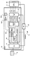
- the control device 5 includes a control unit 50 that controls the ultrasonic motor 3 and a power supply 55 that supplies power to the console 6 and the ultrasonic motor 3.
- the main CPU (control unit) 51 of the control unit 50 is composed of a one-chip microcomputer, and executes processing operations such as predetermined calculation, control, and determination according to a program stored in advance in a memory unit (not shown).
- the memory unit includes a RAM (Random Access Memory) which is a system work memory for operating a main CPU (Central Processing Unit), a ROM (Read Only Memory) storing a program or system software, a hard disk drive, or the like. Prepare.
- a console 6 is connected to the control device 5.
- the main CPU 51 of the control device 5 transmits and receives signals to and from the console 6.
- the main CPU 51 stores the identification data in the memory unit. Further, the main CPU 51 controls the ultrasonic motor 3 based on a program stored in the memory unit.
- the main CPU 51 transmits and receives signals to and from the FPGA (Field-Programmable Gate Array) 56.
- the FPGA 56 includes a speed determination phase control unit 501, a drive signal generation unit 504, and an actual speed detection unit 505.
- a speed determination phase control unit 501 In the control unit 50, a speed determination phase control unit 501, an integration circuit 502, a VCO (Voltage (Controlled Oscillator) 503, a drive signal generation unit 504, and a drive circuit (drive voltage generation unit) 52 are sequentially connected.
- the drive circuit 52 is connected to the ultrasonic motor 3.
- the rotor of the ultrasonic motor 3 is connected to an encoder 39 that outputs a pulse signal corresponding to the rotational speed of the ultrasonic motor 3.
- the encoder 39 outputs a pulse signal to the actual speed detection unit 505.
- a command signal for starting the injection is transmitted from the console 6 to the main CPU 51.
- the main CPU 51 that has received the command signal outputs a set speed signal to the drive signal generation unit 504 to control the drive signal generation unit 504.
- the drive signal generation unit 504 Based on the set speed signal, the drive signal generation unit 504 generates a sin generation signal, a ⁇ sin generation signal, a cos generation signal, a ⁇ cos generation signal, and a phase transition signal as a drive signal for generating a drive voltage. Generate. Then, the drive signal generation unit 504 outputs the drive signal and the phase transition signal to the drive circuit 52.
- the drive circuit 52 that has received the drive signal and the like generates an AC (Alternating Current) voltage (sin wave, -sin wave, cos wave, -cos wave) as a drive voltage for driving the ultrasonic motor 3, Output to the ultrasonic motor 3.
- AC Alternating Current
- the encoder 39 connected to the ultrasonic motor 3 detects the rotation of the ultrasonic motor 3 and sends a pulse signal to the actual speed detection unit 505.
- the actual speed detection unit 505 determines the actual speed and transmits a detected speed signal to the speed determination phase control unit 501.
- the speed determination phase control unit 501 receives a pressure limit signal and a set speed signal from the main CPU 51. Then, the speed determination phase control unit 501 generates a voltage so that the actual speed matches the set speed based on the detected speed signal, the pressure limit signal, and the set speed signal.
- the integration circuit 502 integrates the voltage generated by the speed determination phase control unit 501.
- the VCO 503 converts the integrated drive voltage into a signal having a corresponding frequency.
- the drive signal generation unit 504 converts the signal received from the VCO 503 into a four-phase drive signal, and generates a drive signal (sin generation signal, -sin generation signal, cos generation signal, -cos generation signal). Then, the drive circuit 52 generates a drive voltage based on the drive signal and the phase transition signal received from the drive signal generation unit 504. A signal is also transmitted from the VCO 503 to the speed determination phase control unit 501 and used for feedback control. Thereby, the control unit 50 can control the ultrasonic motor 3 to rotate at the set speed.
- the main CPU 51 transmits a power control signal to the power source 55 to control the supplied power. Then, power is supplied from the power supply 55 to the console 6, the control unit 50 (main CPU 51, FPGA 56, drive circuit 52), and the ultrasonic motor 3.
- the main CPU 51 sets or calculates a rotation speed by using a data table stored in advance in the memory unit, and inputs a set speed signal corresponding to the set or calculated rotation speed to the drive signal generation unit 504. Then, based on the input set speed signal, the drive signal generation unit 504 generates a drive signal for generating a drive voltage for driving the ultrasonic motor 3. Thereafter, the drive signal generation unit 504 outputs a drive signal to the drive circuit 52 that generates a drive voltage. Further, the drive circuit 52 generates and outputs a drive voltage corresponding to the drive signal. Thereby, the ultrasonic motor 3 can be rotated at a desired speed. Note that the main CPU 51 may transmit a set speed signal corresponding to the injection speed input by the operator to the drive signal generation unit 504.
- the main CPU 51 causes the drive signal generation unit 504 to increase the pulse width of the drive voltage stepwise (in order to reduce the frequency) in the order of the high-speed mode, medium-speed mode, low-speed mode, and ultra-low-speed mode.
- a drive signal is generated.
- the high speed mode corresponds to the range of 100.0 rpm to 240.0 rpm (4.2 ml / sec to 10.0 ml / sec), and the medium speed mode is 30.0 rpm to less than 100.0 rpm.
- low speed mode corresponds to the range of 10.0rpm to less than 30.0rpm (0.4ml / sec to 1.2ml / sec)
- ultra low speed mode is 10.0
- the range of less than rpm corresponds to the range of less than rpm (0.3ml / sec or less).
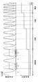
- the main CPU 51 sets the drive signal generation unit 504 so that standby periods t2 and t4 in which the drive voltage is not output are provided after the output periods t1 and t3 in which the drive circuit 52 outputs the drive voltage.
- the drive signal generation unit 504 generates a drive signal based on the set speed signal.
- the drive signal generation unit 504 waits without generating a drive signal based on the set speed signal.
- the drive signal generation unit 504 does not generate and output a drive signal during the standby periods t2 and t4.
- the drive circuit 52 does not generate and output a drive voltage during the standby periods t2 and t4. Therefore, the rotation speed is lower in the ultra-low speed mode than in the low-speed mode.
- the drive voltages during the standby periods t2 and t4 that are not output are indicated by dotted lines.
- the drive signal generation unit 504 of this embodiment does not stand by based on the stop signal input from the switching unit or the like, but waits for a predetermined time based on the input set speed signal. Therefore, it is possible to shorten the standby period until the desired length is reached without depending on the performance of the switching unit. Thereby, even in the ultra-low speed mode, fluctuations in the rotational speed of the ultrasonic motor 3 can be suppressed, so that a constant injection speed can be maintained.
- the standby periods t2 and t4 correspond to a predetermined number of waveform periods of the drive voltage. That is, it is preferable that the main CPU 51 causes the drive signal generation unit 504 to generate a drive signal so that the standby periods t2 and t4 coincide with a predetermined number of waveform periods of the drive voltage.
- the lengths of the output periods t1 and t3 and the standby periods t2 and t4 are times that coincide with one waveform period. Thereby, a driving voltage having a desired frequency can be obtained easily and reliably.
- the frequency of the drive voltage is 22 kHz, which is a half of 44 kHz, and is higher than the audible frequency.
- the frequency of the drive voltage of the ultrasonic motor 3 is not limited to 44 kHz, and may be a frequency in the range of 30 to 50 kHz, for example.
- the standby periods t2 and t4 correspond to one waveform period of the drive voltage. That is, it is more preferable that the main CPU 51 causes the drive signal generation unit 504 to generate a drive signal so that the standby periods t2 and t4 coincide with one waveform cycle of the drive voltage.
- the waiting time can be shortened, so that fluctuations in the rotational speed of the ultrasonic motor can be suppressed even when the injection speed is very low. Therefore, a constant injection rate can be maintained. However, if the injection rate can be kept constant, the waiting period can be made to coincide with two or more waveform periods.
- the output periods t1 and t3 correspond to one waveform period of the drive voltage. That is, the main CPU 51 may cause the drive signal generation unit 504 to generate a drive signal such that output periods t1 and t3 corresponding to one waveform period and standby periods t2 and t4 corresponding to one waveform period are alternately repeated. More preferred. Thereby, the output period t1 for one waveform period, the standby period t2 for one waveform period, the output period t3 for one waveform period, and the standby period t4 for one waveform period are repeated. Then, the drive voltage is applied to the ultrasonic motor 3 at a constant cycle without the standby period being continuous. Therefore, the ultrasonic motor can be stably rotated even in the ultra-low speed mode in which the ultrasonic motor 3 is likely to stop. As a result, the injection rate can be kept constant.
- an output period or a standby period corresponding to two or more waveform periods can be continued.
- an output period that matches two waveform periods and a standby period that matches two waveform periods can be alternately repeated.
- the output period that matches the two waveform periods and the standby period that matches the one waveform period can be alternately repeated.
- the standby period that matches one waveform cycle can be continued once or twice.
- the lengths of the standby periods t2 and t4 are equal to the lengths of the output periods t1 and t3. Thereby, the period during which the drive voltage is applied to the ultrasonic motor 3 and the period during which the drive voltage is not applied are repeated at the same interval. Therefore, the ultrasonic motor can be stably rotated even in the ultra-low speed mode in which the ultrasonic motor 3 is likely to stop. As a result, the injection rate can be kept constant.
- the standby period can be shortened until the desired length is reached based on the input set speed signal. Therefore, the standby period can be shortened without depending on the performance of the switching unit. Thereby, even when the injection speed is very low, fluctuations in the rotational speed of the ultrasonic motor can be suppressed, so that a constant injection speed can be maintained.
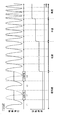
- the drive signal is generated so that the waveform of the drive voltage in the output periods t1 and t3 for outputting the drive voltage is a sine wave.
- the phase of the drive voltage waveform in the output periods t1 and t3 is shifted from the phase of the sine wave. ing.
- the drive voltage includes a sine wave and a ⁇ sin wave as the drive voltage of the first phase, and a cos wave and a ⁇ cos wave as the drive voltage of the second phase, and the first phase and the second phase
- the drive signal is generated so that the phase difference from the phase deviates from 90 degrees.
- the main CPU 51 causes the drive signal generation unit 504 to generate a drive signal so that the output timing of the sine wave and the ⁇ sin wave is shifted or delayed as compared with the first embodiment. Therefore, the drive signal generation unit 504 determines the phase shift amount using the set speed signal received from the main CPU. Then, the drive signal generation unit 504 outputs the drive signal so that the phase difference between the phase of the sine wave and the ⁇ sin wave and the phase of the cos wave and the ⁇ cos wave is shifted from 90 degrees by an amount corresponding to the amount of deviation. Generate. As a result, the phase difference is not 90 degrees. As a result, the rotational speed of the ultrasonic motor 3 is lowered and the injection speed is also lowered. Instead of shifting the output timing of the sin wave and the ⁇ sin wave, the output timing of the cos wave and the ⁇ cos wave may be shifted.
- the output periods t1 and t3 and the standby periods t2 and t4 correspond to one waveform period of the drive voltage, and the output period of one waveform period and the standby period of one waveform period are alternately repeated. More preferably.
- the amount of phase difference deviation can be determined in units of one waveform period in the drive voltage output period. Therefore, the difference between the shift amount determined for each waveform cycle and the actual shift amount is smaller than when the shift amount is determined for a plurality of waveform cycles. As a result, fine control of the injection rate can be performed easily and reliably.
- the waiting period can be shortened until the desired length is reached based on the input set speed signal. Therefore, the standby period can be shortened without depending on the performance of the switching unit. Thereby, even when the injection speed is very low, fluctuations in the rotational speed of the ultrasonic motor can be suppressed, so that a constant injection speed can be maintained.
- the injection speed is further set by setting the phase difference of the drive voltage. Can be controlled more finely.
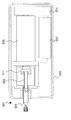
- FIG. 5 is a schematic cross-sectional view of a portable injection device 301 as an example of a chemical solution injection device.
- the ultrasonic motor 317 of the third embodiment is controlled according to the control method described in the first or second embodiment.
- the injection device 301 injects a medical solution such as an infusion solution or an anticancer agent at a low injection rate over a long period of time.
- the injection device 301 includes a sliding portion 316 that slides within the main body 310 in order to advance and retract the plunger 322 of the syringe 321. Further, an ultrasonic motor 317 is provided inside the main body 310 as a drive unit, and is connected to the plunger 322 via the sliding unit 316. A pulley section 371 having a pulley and a belt is connected to the ultrasonic motor 317, and the ultrasonic motor 317 applies a rotational force to the sliding section 316 via the pulley and the belt.
- the sliding portion 316 includes a screw nut that is screwed with a ball screw or a slide screw, and slides within the main body 310 by the rotational force from the ultrasonic motor 317. That is, the sliding portion 316 slides as the screw shaft supported by the bearing rotates by the rotational force from the ultrasonic motor 317.
- the sliding portion 316 is connected to the plunger 322 via the mounting portion 311. As the sliding portion 316 slides in the main body 310, the plunger 322 moves forward or backward.
- the sliding portion 316 includes a ball screw shaft that is rotatably supported by the bearing, and a ball screw nut that is screwed into an intermediate portion of the ball screw shaft. Then, the ball screw nut engages with a plunger hook (mounting portion) 311 slidably attached to the main body 310.
- the rotation of the rotating shaft of the ultrasonic motor 317 is transmitted to the ball screw shaft via a pulley and a belt (pulley portion 371). Thereby, the ball screw shaft rotates according to the transmitted rotational force, and the ball screw nut slides with the rotation of the ball screw shaft.
- the plunger 322 moves forward or backward via the plunger hook 311. That is, the plunger 322 is taken in and out of the syringe 321.
- the chemical liquid flows into the syringe 321 from a chemical liquid bag (not shown).
- the plunger 322 moves forward, the drug solution in the syringe 321 flows out into the tube and is injected into the user via the catheter. By repeating the forward and reverse movements, the chemical solution can be injected into the user continuously for a long time.
- the main body 310 of the injection apparatus 301 includes the control unit 50 (not shown) described above in order to control the ultrasonic motor 317.
- the drive signal generation unit 504 waits without generating a drive signal based on the set speed signal in the standby periods t2 and t4 following the output periods t1 and t3 for outputting the drive voltage.
- the standby period coincides with one waveform cycle. More preferably, the output period corresponding to one waveform period and the standby period corresponding to one waveform period are alternately repeated.
- the waiting period can be shortened until the desired length is reached based on the input set speed signal. Therefore, the standby period can be shortened without depending on the performance of the switching unit. Thereby, even when the injection speed is very low, fluctuations in the rotational speed of the ultrasonic motor can be suppressed, so that a constant injection speed can be maintained.
- the drive signal can be generated so that the phase difference between the first phase and the second phase of the drive voltage is shifted from 90 degrees.
- the mode of the rotational speed of the ultrasonic motor 3 is not limited to four stages, and modes of three stages or less or five stages or more can be provided.
- the voltage value or frequency of the drive voltage to be output can be changed so as to achieve a desired rotational speed within the range of the injection speed corresponding to each mode. Thereby, in each mode, the rotational speed of the ultrasonic motor can be controlled so as to achieve a desired injection speed.
- the injection device may include a driving device in which the ultrasonic motor 3 and the control unit 50 are integrally provided, and the driving mechanism 4 may be driven by the driving device.
- the drive voltage generation unit can be configured by integrally providing the drive signal generation unit 504 and the drive circuit 52.
Landscapes
- Health & Medical Sciences (AREA)
- Vascular Medicine (AREA)
- Engineering & Computer Science (AREA)
- Anesthesiology (AREA)
- Biomedical Technology (AREA)
- Heart & Thoracic Surgery (AREA)
- Hematology (AREA)
- Life Sciences & Earth Sciences (AREA)
- Animal Behavior & Ethology (AREA)
- General Health & Medical Sciences (AREA)
- Public Health (AREA)
- Veterinary Medicine (AREA)
- Infusion, Injection, And Reservoir Apparatuses (AREA)
- Apparatuses For Generation Of Mechanical Vibrations (AREA)
- General Electrical Machinery Utilizing Piezoelectricity, Electrostriction Or Magnetostriction (AREA)
Applications Claiming Priority (2)
| Application Number | Priority Date | Filing Date | Title |
|---|---|---|---|
| JP2013240987A JP6280351B2 (ja) | 2013-11-21 | 2013-11-21 | 超音波モーターの制御方法、及び注入装置 |
| JP2013-240987 | 2013-11-21 |
Publications (1)
| Publication Number | Publication Date |
|---|---|
| WO2015075936A1 true WO2015075936A1 (ja) | 2015-05-28 |
Family
ID=53179218
Family Applications (1)
| Application Number | Title | Priority Date | Filing Date |
|---|---|---|---|
| PCT/JP2014/005838 Ceased WO2015075936A1 (ja) | 2013-11-21 | 2014-11-20 | 超音波モーターの制御方法、及び注入装置 |
Country Status (2)
| Country | Link |
|---|---|
| JP (1) | JP6280351B2 (enExample) |
| WO (1) | WO2015075936A1 (enExample) |
Families Citing this family (1)
| Publication number | Priority date | Publication date | Assignee | Title |
|---|---|---|---|---|
| US11666710B2 (en) * | 2020-04-14 | 2023-06-06 | Bluerock Therapeutics Lp | Delivery devices for therapeutic substances |
Citations (3)
| Publication number | Priority date | Publication date | Assignee | Title |
|---|---|---|---|---|
| JPH07222466A (ja) * | 1994-01-27 | 1995-08-18 | Matsushita Electric Ind Co Ltd | 超音波モータの制御装置 |
| JP2003290349A (ja) * | 2002-01-30 | 2003-10-14 | Nemoto Kyorindo:Kk | Mri対応注入装置 |
| JP2007244181A (ja) * | 2006-03-13 | 2007-09-20 | Konica Minolta Opto Inc | 駆動装置 |
-
2013
- 2013-11-21 JP JP2013240987A patent/JP6280351B2/ja active Active
-
2014
- 2014-11-20 WO PCT/JP2014/005838 patent/WO2015075936A1/ja not_active Ceased
Patent Citations (3)
| Publication number | Priority date | Publication date | Assignee | Title |
|---|---|---|---|---|
| JPH07222466A (ja) * | 1994-01-27 | 1995-08-18 | Matsushita Electric Ind Co Ltd | 超音波モータの制御装置 |
| JP2003290349A (ja) * | 2002-01-30 | 2003-10-14 | Nemoto Kyorindo:Kk | Mri対応注入装置 |
| JP2007244181A (ja) * | 2006-03-13 | 2007-09-20 | Konica Minolta Opto Inc | 駆動装置 |
Also Published As
| Publication number | Publication date |
|---|---|
| JP6280351B2 (ja) | 2018-02-14 |
| JP2015100725A (ja) | 2015-06-04 |
Similar Documents
| Publication | Publication Date | Title |
|---|---|---|
| JP7239223B2 (ja) | 薬液注入装置および薬液注入システム | |
| CN113663166B (zh) | 双边驱动的智能控制输注装置及闭环人工胰腺 | |
| JP6817644B2 (ja) | 注入装置及び注入装置の制御装置 | |
| JPH0584296A (ja) | 医療用注入機器 | |
| JP6884367B2 (ja) | 注入プロトコルの生成装置、該生成装置を備える注入装置及び撮像システム、注入プロトコル生成方法、及び注入プロトコル生成プログラム | |
| JP4907738B1 (ja) | 注入機器及び超音波モータの制御方法 | |
| JP6298811B2 (ja) | 薬液注入装置 | |
| JP6966112B2 (ja) | 注入装置及び撮像システム | |
| CN115209930B (zh) | 具有用于控制输送速率的经改进机构的药物输送装置 | |
| CN106492311A (zh) | 一种手持式可辅助注射器自动抽吸和注射的装置 | |
| US20100274182A1 (en) | Power Injector with Flow Rate Assessment | |
| JP5468456B2 (ja) | 薬液注入装置 | |
| JP2015181869A (ja) | 薬液投与装置 | |
| JP2024040279A (ja) | 薬液注入装置 | |
| CN102067139A (zh) | 保持静脉张开功能的动力注射器 | |
| JP6280351B2 (ja) | 超音波モーターの制御方法、及び注入装置 | |
| Ali | Designing a low-cost and portable infusion pump | |
| KR101648056B1 (ko) | 자동약액주입장치 | |
| JP6104538B2 (ja) | 注入機器及び注入圧力を求める方法 | |
| JP6316618B2 (ja) | 注入装置及びアダプタ検出装置 | |
| JP4276410B2 (ja) | Mri対応注入装置 | |
| JP2013192850A (ja) | 薬液投与装置 | |
| WO2013153913A1 (ja) | 薬液注入装置 | |
| JP6240132B2 (ja) | 注入機器及び超音波モータの制御方法 | |
| JP4808213B2 (ja) | 薬液注入装置 |
Legal Events
| Date | Code | Title | Description |
|---|---|---|---|
| 121 | Ep: the epo has been informed by wipo that ep was designated in this application |
Ref document number: 14863937 Country of ref document: EP Kind code of ref document: A1 |
|
| NENP | Non-entry into the national phase |
Ref country code: DE |
|
| 122 | Ep: pct application non-entry in european phase |
Ref document number: 14863937 Country of ref document: EP Kind code of ref document: A1 |