WO2015075872A1 - ヒートポンプシステム - Google Patents
ヒートポンプシステム Download PDFInfo
- Publication number
- WO2015075872A1 WO2015075872A1 PCT/JP2014/005501 JP2014005501W WO2015075872A1 WO 2015075872 A1 WO2015075872 A1 WO 2015075872A1 JP 2014005501 W JP2014005501 W JP 2014005501W WO 2015075872 A1 WO2015075872 A1 WO 2015075872A1
- Authority
- WO
- WIPO (PCT)
- Prior art keywords
- heat
- refrigerant
- heat exchanger
- heating
- heat medium
- Prior art date
Links
Images


Classifications
-
- B—PERFORMING OPERATIONS; TRANSPORTING
- B60—VEHICLES IN GENERAL
- B60H—ARRANGEMENTS OF HEATING, COOLING, VENTILATING OR OTHER AIR-TREATING DEVICES SPECIALLY ADAPTED FOR PASSENGER OR GOODS SPACES OF VEHICLES
- B60H1/00—Heating, cooling or ventilating [HVAC] devices
- B60H1/00642—Control systems or circuits; Control members or indication devices for heating, cooling or ventilating devices
- B60H1/00814—Control systems or circuits characterised by their output, for controlling particular components of the heating, cooling or ventilating installation
- B60H1/00878—Control systems or circuits characterised by their output, for controlling particular components of the heating, cooling or ventilating installation the components being temperature regulating devices
- B60H1/00899—Controlling the flow of liquid in a heat pump system
- B60H1/00921—Controlling the flow of liquid in a heat pump system where the flow direction of the refrigerant does not change and there is an extra subcondenser, e.g. in an air duct
-
- B—PERFORMING OPERATIONS; TRANSPORTING
- B60—VEHICLES IN GENERAL
- B60H—ARRANGEMENTS OF HEATING, COOLING, VENTILATING OR OTHER AIR-TREATING DEVICES SPECIALLY ADAPTED FOR PASSENGER OR GOODS SPACES OF VEHICLES
- B60H1/00—Heating, cooling or ventilating [HVAC] devices
- B60H1/32—Cooling devices
- B60H1/3204—Cooling devices using compression
- B60H1/3228—Cooling devices using compression characterised by refrigerant circuit configurations
- B60H1/32281—Cooling devices using compression characterised by refrigerant circuit configurations comprising a single secondary circuit, e.g. at evaporator or condenser side
-
- F—MECHANICAL ENGINEERING; LIGHTING; HEATING; WEAPONS; BLASTING
- F25—REFRIGERATION OR COOLING; COMBINED HEATING AND REFRIGERATION SYSTEMS; HEAT PUMP SYSTEMS; MANUFACTURE OR STORAGE OF ICE; LIQUEFACTION SOLIDIFICATION OF GASES
- F25B—REFRIGERATION MACHINES, PLANTS OR SYSTEMS; COMBINED HEATING AND REFRIGERATION SYSTEMS; HEAT PUMP SYSTEMS
- F25B47/00—Arrangements for preventing or removing deposits or corrosion, not provided for in another subclass
- F25B47/02—Defrosting cycles
-
- F—MECHANICAL ENGINEERING; LIGHTING; HEATING; WEAPONS; BLASTING
- F25—REFRIGERATION OR COOLING; COMBINED HEATING AND REFRIGERATION SYSTEMS; HEAT PUMP SYSTEMS; MANUFACTURE OR STORAGE OF ICE; LIQUEFACTION SOLIDIFICATION OF GASES
- F25B—REFRIGERATION MACHINES, PLANTS OR SYSTEMS; COMBINED HEATING AND REFRIGERATION SYSTEMS; HEAT PUMP SYSTEMS
- F25B49/00—Arrangement or mounting of control or safety devices
- F25B49/02—Arrangement or mounting of control or safety devices for compression type machines, plants or systems
-
- B—PERFORMING OPERATIONS; TRANSPORTING
- B60—VEHICLES IN GENERAL
- B60H—ARRANGEMENTS OF HEATING, COOLING, VENTILATING OR OTHER AIR-TREATING DEVICES SPECIALLY ADAPTED FOR PASSENGER OR GOODS SPACES OF VEHICLES
- B60H1/00—Heating, cooling or ventilating [HVAC] devices
- B60H1/00642—Control systems or circuits; Control members or indication devices for heating, cooling or ventilating devices
- B60H1/00814—Control systems or circuits characterised by their output, for controlling particular components of the heating, cooling or ventilating installation
- B60H1/00878—Control systems or circuits characterised by their output, for controlling particular components of the heating, cooling or ventilating installation the components being temperature regulating devices
- B60H2001/00961—Control systems or circuits characterised by their output, for controlling particular components of the heating, cooling or ventilating installation the components being temperature regulating devices comprising means for defrosting outside heat exchangers
-
- F—MECHANICAL ENGINEERING; LIGHTING; HEATING; WEAPONS; BLASTING
- F25—REFRIGERATION OR COOLING; COMBINED HEATING AND REFRIGERATION SYSTEMS; HEAT PUMP SYSTEMS; MANUFACTURE OR STORAGE OF ICE; LIQUEFACTION SOLIDIFICATION OF GASES
- F25B—REFRIGERATION MACHINES, PLANTS OR SYSTEMS; COMBINED HEATING AND REFRIGERATION SYSTEMS; HEAT PUMP SYSTEMS
- F25B2347/00—Details for preventing or removing deposits or corrosion
- F25B2347/02—Details of defrosting cycles
-
- F—MECHANICAL ENGINEERING; LIGHTING; HEATING; WEAPONS; BLASTING
- F25—REFRIGERATION OR COOLING; COMBINED HEATING AND REFRIGERATION SYSTEMS; HEAT PUMP SYSTEMS; MANUFACTURE OR STORAGE OF ICE; LIQUEFACTION SOLIDIFICATION OF GASES
- F25B—REFRIGERATION MACHINES, PLANTS OR SYSTEMS; COMBINED HEATING AND REFRIGERATION SYSTEMS; HEAT PUMP SYSTEMS
- F25B2400/00—General features or devices for refrigeration machines, plants or systems, combined heating and refrigeration systems or heat-pump systems, i.e. not limited to a particular subgroup of F25B
- F25B2400/05—Compression system with heat exchange between particular parts of the system
Definitions
- the present disclosure relates to a heat pump system that heats a fluid to be heated by a heat pump cycle.
- a heat pump system for heating a fluid to be heated by a heat pump cycle (vapor compression refrigeration cycle) is known.
- a heat pump cycle applied to this type of system when the refrigerant evaporation temperature in the outdoor heat exchanger functioning as an evaporator that exchanges heat with the outside air to evaporate falls to 0 ° C. or lower, it reaches the outdoor heat exchanger. Frost may occur.
- defrosting is performed by flowing high-temperature and high-pressure refrigerant (hot gas) discharged from the compressor of the heat pump cycle into the outdoor heat exchanger.
- hot gas defrosting So-called hot gas defrosting is also known.
- the defrosting time becomes relatively long, and the energy consumed by the compressor for defrosting increases.
- Patent Document 1 is a heat pump system applied to an air conditioner for a vehicle, in which outdoor heat in which frost is generated using waste heat stored in cooling water for cooling an in-vehicle electric device as a heat source. What performs defrosting of the exchanger is disclosed.
- the defrost of an outdoor heat exchanger since the defrost of an outdoor heat exchanger is performed using the waste heat of a vehicle-mounted electric equipment, it will increase that the energy which a compressor consumes for defrost is increased. Can be suppressed.
- the present disclosure can realize defrosting or suppressing frosting of the outdoor heat exchanger without increasing the energy consumption of the compressor of the heat pump cycle, regardless of the heat supplied from the outside.
- An object of the present invention is to provide a simple heat pump system.
- a heat pump system includes a heat pump cycle, a heat medium circulation circuit, and a heat medium heat dissipation unit.
- the heat pump cycle is a compressor that compresses and discharges refrigerant, a heat medium-refrigerant heat exchanger that exchanges heat between the high-pressure refrigerant discharged from the compressor and the heat medium, and refrigerant that flows out of the heat medium-refrigerant heat exchanger.
- a decompression device for decompressing and an outdoor heat exchanger for exchanging heat between the refrigerant decompressed by the decompression device and the outside air are provided.
- the heating medium circulation circuit includes a heating heat exchanger that circulates the heating medium and heats the heating target fluid by exchanging heat between the heating medium flowing out of the heating medium-refrigerant heat exchanger and the heating target fluid.
- a heating heat exchanger that circulates the heating medium and heats the heating target fluid by exchanging heat between the heating medium flowing out of the heating medium-refrigerant heat exchanger and the heating target fluid.
- the heat of the heat medium flowing out from the heat exchanger for heating is radiated to the low-pressure refrigerant flowing through the range from the decompression device outlet side to the compressor suction port.
- the heat medium heat radiating section since the heat medium heat radiating section is provided, the heat of the heat medium circulating in the heat medium circulation circuit can be radiated to the low-pressure refrigerant. And it can defrost an outdoor heat exchanger and the frost formation of an outdoor heat exchanger with the heat radiated from the heat medium to the low-pressure refrigerant.
- the heat of the heat medium flowing out from the heat exchanger for heating is radiated to the low-pressure refrigerant, so that the heat of the heat medium heated in the heat medium-refrigerant heat exchanger is heated. It can be preferentially used for heating, and the excess heat can be used for defrosting or suppressing frost formation in the outdoor heat exchanger. Therefore, it is possible to realize defrosting or suppressing frosting of the outdoor heat exchanger without increasing the energy consumption of the compressor.
- a heat pump system capable of realizing defrosting or suppressing frosting of the outdoor heat exchanger without depending on the heat supplied from an external heat source or the like and without increasing the energy consumption of the compressor of the heat pump cycle. Can be provided.
- the heat medium heat radiating unit is composed of a heat medium heat radiating heat exchanger that exchanges heat between the heat medium flowing out from the heating heat exchanger and the outside air, and the heat medium radiating heat exchanger and the outdoor heat exchange.
- the vessel may be integrated so as to enable heat transfer between the heat medium flowing through the heat exchanger for heat medium heat dissipation and the refrigerant flowing through the outdoor heat exchanger.
- circulates the heat exchanger for heat-medium heat dissipation can be directly transferred to an outdoor heat exchanger, and effective defrosting of an outdoor heat exchanger or effective Suppressing frost formation can be realized.
- the heat medium heat radiating section is composed of a heat medium heat radiating heat exchanger that exchanges heat between the heat medium flowing out from the heating heat exchanger and the outside air
- the outdoor heat exchanger is a heat medium radiating heat You may arrange
- circulates the heat exchanger for heat-medium heat radiation can be indirectly transferred to an outdoor heat exchanger via outside air, and defrosting or attachment of an outdoor heat exchanger is possible. Suppression of frost can be easily realized.
- the heat medium heat radiating section may be configured by a heat medium heat radiating heat exchanger that exchanges heat between the heat medium flowing out from the heating heat exchanger and the low-pressure refrigerant.
- the heat of the heat medium flowing through the heat exchanger for radiating the heat medium can be absorbed by the low-pressure refrigerant, the refrigerant evaporating temperature in the outdoor heat exchanger is raised and frost formation is suppressed. can do.
- a heat medium flow adjustment device for adjusting the flow rate of the heat medium flowing out from the heat exchanger for heating and flowing into the heat exchanger for heat medium heat dissipation is provided. It may be.
- the amount of heat radiated from the heat medium to the low-pressure refrigerant can be appropriately adjusted according to the heating capacity of the heating target fluid required for the heat pump cycle.
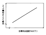
- FIG. 3 is a cross-sectional view taken along the line III-III in FIG. It is a control characteristic figure which shows the relationship between target blowing temperature TAO and bypass flow volume.
- TAO target blowing temperature
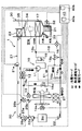
- It is a typical whole block diagram of the heat pump system of 2nd Embodiment. It is a typical whole block diagram of the heat pump system of 3rd Embodiment. It is a typical whole block diagram of the heat pump system of 4th Embodiment. It is a typical whole block diagram of the heat pump system of 5th Embodiment.
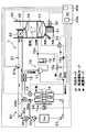
- the heat pump system 1 is applied to a vehicle air conditioner for a so-called hybrid vehicle that obtains a driving force for vehicle traveling from an internal combustion engine (engine) and a traveling electric motor.
- the heat pump system 1 of the present embodiment fulfills the function of heating or cooling the blown air blown into the vehicle interior, which is the air conditioning target space, in the vehicle air conditioner.
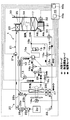
- the heat pump system 1 of the present embodiment circulates a heat pump cycle 10 that is a vapor compression refrigeration cycle that heats or cools blown air, and cooling water (for example, an ethylene glycol aqueous solution) that is a heat medium.
- the heat medium circulation circuit 20 is provided. And when blowing air is heated, cooling water is heated with the heat pump cycle 10, and blowing air is heated by using the heated cooling water as a heat source. Therefore, the fluid to be heated in the heat pump system 1 of the present embodiment is blown air.
- the heat pump cycle 10 of the present embodiment includes a cooling mode refrigerant circuit that cools the blown air to cool the vehicle interior, a heating mode refrigerant circuit that heats the blown air and heats the vehicle interior, It is configured to be switchable to a refrigerant circuit in a dehumidifying and heating mode in which heating is performed while dehumidifying the vehicle interior by heating the dehumidified blown air.
- the refrigerant flow in the cooling mode refrigerant circuit is indicated by a white arrow
- the refrigerant flow in the heating mode refrigerant circuit is indicated by a solid arrow
- the refrigerant flow in the dehumidifying heating mode refrigerant circuit is hatched. Shown with hatched arrows.
- the heat pump cycle 10 employs an HFC refrigerant (specifically, R134a) as the refrigerant, and a vapor compression subcritical refrigeration cycle in which the high-pressure side refrigerant pressure Pd of the cycle does not exceed the critical pressure of the refrigerant.
- HFC refrigerant specifically, R134a
- coolants for example, R1234yf
- refrigeration oil for lubricating the compressor 11 is mixed in the refrigerant, and a part of the refrigeration oil circulates in the cycle together with the refrigerant.
- the compressor 11 is disposed in the engine room, and sucks the refrigerant in the heat pump cycle 10 and discharges it until it becomes a high-pressure refrigerant.
- the compressor 11 of the present embodiment is an electric compressor configured by housing a fixed capacity type compression mechanism and an electric motor that drives the compression mechanism in one housing.
- various compression mechanisms such as a scroll-type compression mechanism and a vane-type compression mechanism can be employed. Further, the operation (rotation speed) of the electric motor is controlled by a control signal output from the air conditioning control device 40 described later, and either an AC motor or a DC motor may be adopted.
- the refrigerant inlet side of the refrigerant passage of the high temperature side water-refrigerant heat exchanger 12 is connected to the discharge port side of the compressor 11.
- the high-temperature side water-refrigerant heat exchanger 12 heat-exchanges the high-pressure refrigerant discharged from the compressor 11 and the cooling water circulating in the heat medium circulation circuit 20 to heat the cooling water. It is.
- a plurality of tubes through which high-pressure refrigerant is circulated are provided as high-pressure refrigerant passages, and water passages through which cooling water is circulated between adjacent tubes are formed.
- a heat exchanger or the like configured by disposing inner fins that promote heat exchange between the refrigerant and the cooling water in the passage can be employed.
- the inlet side of the heating expansion valve 13 is connected to the outlet side of the refrigerant passage of the high temperature side water-refrigerant heat exchanger 12.
- the heating expansion valve 13 is a pressure reducing device that depressurizes the high-pressure refrigerant that has flowed out of the high-temperature side water-refrigerant heat exchanger 12 at least in the heating mode, and includes a valve body configured to be able to change the throttle opening,
- This is an electric variable throttle mechanism that includes an electric actuator including a stepping motor that changes the throttle opening by displacing the body.
- the heating expansion valve 13 of the present embodiment is configured by a variable throttle mechanism with a full-open function that functions as a simple refrigerant passage without exerting almost any refrigerant decompression action by fully opening the throttle opening.
- the operation of the heating expansion valve 13 is controlled by a control signal output from the air conditioning control device 40.
- the refrigerant inlet side of the outdoor heat exchanger 14 is connected to the outlet side of the heating expansion valve 13.
- the outdoor heat exchanger 14 is a heat exchanger that is disposed on the front side in the engine room and exchanges heat between the refrigerant on the downstream side of the high-temperature side water-refrigerant heat exchanger 12 and the outside air blown from the blower fan 14a. .
- the outdoor heat exchanger 14 functions as a radiator that radiates high-pressure refrigerant at least in the cooling mode, and at least in the heating mode, the outdoor heat exchanger 14 receives the low-pressure refrigerant decompressed by the heating expansion valve 13 that is a decompression device. It functions as an evaporator that evaporates and exerts an endothermic effect.
- the blower fan 14a is an electric blower in which the operating rate, that is, the rotation speed (blowing capacity) is controlled by the control voltage output from the air conditioning control device 40.
- the outdoor heat exchanger 14 of this embodiment is configured integrally with a radiator 24 described later.
- the ventilation fan 14a of this embodiment fulfill
- FIG. The detailed configuration of the integrated outdoor heat exchanger 14 and radiator 24 (hereinafter referred to as heat exchanger structure 60) will be described later.
- the refrigerant outlet side of the outdoor heat exchanger 14 is connected to the refrigerant inlet of the low-pressure side branch portion 15a that branches the flow of the refrigerant flowing out of the outdoor heat exchanger 14.
- the low-pressure side branching portion 15a is configured by a three-way joint, and one of the three inflow / outflow ports is a refrigerant inflow port, and the remaining two are refrigerant outflow ports.
- Such a three-way joint may be formed by joining pipes having different pipe diameters, or may be formed by providing a plurality of refrigerant passages in a metal block or a resin block.
- the refrigerant inlet side of the cooling expansion valve 16 is connected to one refrigerant outlet of the low-pressure side branch 15a via a check valve 16a, and the other refrigerant outlet flows out of the low-pressure side branch 15a.
- An inlet side of an accumulator side passage 18 that guides the refrigerant to the upstream side of an accumulator 19 described later by bypassing the cooling expansion valve 16 and the like is connected.
- the check valve 16a only allows the refrigerant flowing out from one refrigerant outlet of the low pressure side branch portion 15a to flow from the low pressure side branch portion 15a to the cooling expansion valve 16 side.
- the basic configuration of the cooling expansion valve 16 is the same as that of the heating expansion valve 13. Furthermore, the cooling expansion valve 16 of the present embodiment has only a fully open function that fully opens the refrigerant passage from the refrigerant outlet side of the outdoor heat exchanger 14 to the refrigerant inlet side of the indoor evaporator 17 when the throttle opening is fully opened. First, it is composed of a variable throttle mechanism with a full-close function that closes the refrigerant passage when the throttle opening is fully closed.
- the refrigerant circuit for circulating the refrigerant can be switched by the cooling expansion valve 16 closing the refrigerant passage in this way. Therefore, the cooling expansion valve 16 of the present embodiment constitutes a refrigerant circuit switching unit.
- the refrigerant inlet side of the indoor evaporator 17 is connected to the outlet side of the cooling expansion valve 16.
- the indoor evaporator 17 is disposed in a casing 31 of an indoor air conditioning unit 30 described later, and blown air by evaporating the refrigerant flowing through the interior at least in the cooling mode and the dehumidifying heating mode by exchanging heat with the blown air. It is a heat exchanger for cooling which cools.
- the inlet side of the accumulator 19 is connected to the refrigerant outlet side of the indoor evaporator 17 via a junction 15b.
- the accumulator 19 is a gas-liquid separator that separates the gas-liquid refrigerant flowing into the accumulator 19 and stores excess refrigerant in the cycle.
- the merging portion 15b is configured by a three-way joint similar to the low-pressure side branching portion 15a, and two of the three inflow / outflow ports are refrigerant inlets and the remaining one is a refrigerant outlet.
- the outlet side of the accumulator side passage 18 is connected to the other refrigerant inlet of the junction 15b of the present embodiment.
- the accumulator side passage 18 is provided with a heating on-off valve 18 a for opening and closing the accumulator side passage 18.
- the heating on / off valve 18 a is an electromagnetic valve whose opening / closing operation is controlled by a control voltage output from the air conditioning control device 40, and constitutes a refrigerant circuit switching unit together with the cooling expansion valve 16.
- the suction side of the compressor 11 is connected to the gas phase refrigerant outlet of the accumulator 19. Accordingly, the accumulator 19 functions to prevent liquid compression of the compressor 11 by suppressing the liquid phase refrigerant from being sucked into the compressor 11.
- the heat medium circulation circuit 20 will be described.
- the heat medium circulation circuit 20 of this embodiment is roughly divided into a high-pressure side heat medium circulation circuit 21 and a low-pressure side heat medium circulation circuit 22.
- the high-pressure side heat medium circuit 21 and the low-pressure side heat medium circuit 22 communicate with each other. Therefore, in the heat medium circulation circuit 20, as will be described later, a part of the cooling water circulating in the high pressure side heat medium circulation circuit 21 flows into the low pressure side heat medium circulation circuit 22, and the low pressure side heat medium circulation circuit 22. A part of the cooling water circulating through the high pressure side heat medium circulation circuit 21 can be made to flow.
- the high-pressure side heat medium circuit 21 is a heat medium circuit that circulates cooling water mainly between the high-temperature side water-refrigerant heat exchanger 12 and the heater core 23.
- the heater core 23 is disposed in the casing 31 of the indoor air conditioning unit 30 to exchange heat between the cooling water heated by the high temperature side water-refrigerant heat exchanger 12 and the blown air after passing through the indoor evaporator 17. It is a heat exchanger for heating which heats blowing air.
- the high-pressure side heat medium circulation circuit 21 is provided with a high-temperature side water pump 21 a that pumps the cooling water flowing out from the high-temperature side water-refrigerant heat exchanger 12 toward the heater core 23.
- the high temperature side water pump 21 a is an electric pump whose rotation speed (water pressure feeding capacity) is controlled by a control voltage output from the air conditioning control device 40.
- the high-pressure side heat medium circulation circuit 21 mainly operates as shown by the solid arrow in FIG.
- the cooling water circulates in the order of the water passage of the heat exchanger 12 ⁇ the heater core 23 ⁇ the high temperature side water pump 21a.
- the cooling water heated by the high temperature side water-refrigerant heat exchanger 12 can be caused to flow into the heater core 23 to heat the blown air.
- the low-pressure side heat medium circulation circuit 22 mainly circulates the cooling water between the radiator 24 and the cooling water passage provided in the inverter Inv that supplies electric power to the electric motor for traveling. Circuit.
- the radiator 24 is disposed in the engine room and heat-exchanges heat for radiating the cooling water by exchanging heat between the cooling water circulating in the low-pressure side heat medium circulation circuit 22 and the outside air blown from the blower fan 14a. It is an exchanger.
- the inverter Inv is an in-vehicle device that generates heat during operation, and also functions as an external heat source for heating the cooling water flowing into the radiator 24.
- the low-pressure side heat medium circulation circuit 22 is provided with a low-temperature side water pump 22 a that pumps the cooling water flowing out from the cooling water passage provided in the inverter Inv toward the radiator 24.
- the basic configuration of the low temperature side water pump 22a is the same as that of the high temperature side water pump 21a.
- the low-pressure side heat medium circulation circuit 22 is provided in the low-temperature side water pump 22a ⁇ the inverter Inv mainly as shown by the broken-line arrows in FIG.
- the cooling water circulates in the order of the cooling water passage ⁇ the radiator 24 ⁇ the low temperature side water pump 22a.
- the cooling water passes through the cooling water passage, the waste heat of the inverter Inv is absorbed, and the heat absorbed when the cooling water flows through the radiator 24 can be radiated to the outside air, thereby cooling the inverter Inv. be able to.
- the inverter Inv as an external heat source, the temperature of the cooling water flowing into the radiator 24 can be raised, and the temperature of the outside air blown to the outdoor heat exchanger 14 can be raised.
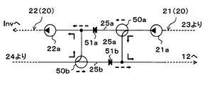
- the discharge port side of the high temperature side water pump 21a of the high pressure side heat medium circulation circuit 21 and the suction port side of the low temperature side water pump 22a of the low pressure side heat medium circulation circuit 22 are connected via the first connection flow path 25a.
- the outlet side of the radiator 24 of the low-pressure side heat medium circulation circuit 22 and the inlet side of the water passage of the high-temperature side water-refrigerant heat exchanger 12 of the high-pressure side heat medium circulation circuit 21 are connected via a second connection flow path 25b. ing.
- a first cooling water flow rate adjusting valve 26a for adjusting the flow rate of the cooling water flowing through the first connecting flow channel 25a is disposed in the first connecting flow channel 25a.
- a second cooling water flow rate adjustment valve 26b that adjusts the flow rate of the cooling water flowing through the second connection flow channel 25b is disposed in the second connection flow channel 25b.
- Each of the first and second cooling water flow rate adjusting valves 26a and 26b includes a valve body configured to change the opening degree and an electric actuator that changes the opening degree by displacing the valve body. This is an electric flow control valve.
- the operations of the first and second cooling water flow rate adjustment valves 26 a and 26 b are controlled by a control signal output from the air conditioning control device 40.
- the high-pressure side heat medium circulation circuit 21 includes the high-temperature side water-refrigerant heat exchanger 12, the heater core 23, In the low-pressure side heat medium circuit 22, the cooling water circulates between the radiator 24 and the inverter Inv. Therefore, the cooling water circulating through the high-pressure side heat medium circulation circuit 21 and the cooling water circulating through the low-pressure side heat medium circulation circuit 22 do not mix.
- the air conditioning control device 40 opens the first and second cooling water flow rate adjustment valves 26a and 26b, a part of the cooling water that circulates through the high-pressure side heat medium circulation circuit 21 according to the opening degree. However, a part of the cooling water that flows into the low-pressure side heat medium circulation circuit 22 through the first connection flow path 25a and the high-pressure flow through the low-pressure side heat medium circulation circuit 22 passes through the second connection flow path 25b. It flows into the side heat medium circulation circuit 21.
- a part of the cooling water flowing out from the heater core 23 can be made to flow into the inverter Inv by opening the first and second cooling water flow rate adjusting valves 26a and 26b. Furthermore, the cooling water flowing out from the inverter Inv can be introduced into the radiator 24, and a part of the cooling water flowing out from the radiator 24 can be returned to the water passage side of the high temperature side water-refrigerant heat exchanger 12.
- the air-conditioning control device 40 adjusts the opening degree of the first and second cooling water flow rate adjustment valves 26a and 26b, so that the cooling water flowing out from the heater core 23 arranged in the high-pressure side heat medium circulation circuit 21.
- the flow rate of the cooling water flowing into the radiator 24 arranged in the low-pressure side heat medium circulation circuit 22 can be adjusted.
- the first and second cooling water flow rate adjustment valves 26a and 26b constitute the heat medium flow rate adjustment device described in the claims.
- the air conditioning control device 40 opens the first and second cooling water flow rate adjusting valves 26a and 26b, the flow rate and the low pressure side heat flowing from the high pressure side heat medium circulation circuit 21 to the low pressure side heat medium circulation circuit 22 are opened.
- the flow rate returning from the medium circulation circuit 22 to the high-pressure side heat medium circulation circuit 21 may transiently differ, the flow rate eventually converges to the same flow rate.
- the flow rate after convergence is described as a bypass flow rate.
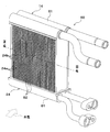
- the outdoor heat exchanger 14 and the radiator 24 of the present embodiment are each provided with a plurality of tubes through which the refrigerant or cooling water flows, and the refrigerant or cooling water that is arranged on both ends of the plurality of tubes and flows through the tubes. It is configured as a so-called tank-and-tube type heat exchanger having a pair of collecting / distributing tanks for collecting or distributing.
- the outdoor heat exchanger 14 has a plurality of refrigerant tubes 14a through which the refrigerant flows.
- the refrigerant tube 14a as shown in the cross-sectional view of FIG. 3, a multi-hole flat tube having a flat vertical cross-sectional shape in the longitudinal direction is adopted, and each of the refrigerant tubes 14a has an outer surface.
- the flat surfaces are laminated and arranged at a predetermined interval so that they are opposed to each other in parallel.
- an endothermic air passage 14b through which the outside air blown from the blower fan 14a is circulated is formed around the refrigerant tube 14a, that is, between the adjacent refrigerant tubes 14a.
- the radiator 24 has a plurality of heat medium tubes 24a through which cooling water flows.
- the heat medium tube 24a as shown in the cross-sectional view of FIG. 3, a single-hole flat tube having a flat vertical cross-sectional shape in the longitudinal direction is adopted, and similarly to the refrigerant tube 14a, the heat medium The tubes 24a are laminated and arranged at predetermined intervals so that the flat surfaces of the outer surface are parallel to each other and face each other.
- a heat radiation air passage 24b is formed around the heat medium tube 24a, that is, between the adjacent heat medium tubes 24a, for circulating the outside air blown from the blower fan 14a.
- a part of the collective distribution tank 61 of the outdoor heat exchanger 14 and the radiator 24 is formed by the same member, and the heat absorbing air passage 14b and the heat radiating air passage 24b are formed by the same member.
- the outer fin 62 is disposed.
- the outdoor heat exchanger 14 and the radiator 24 are integrated as the heat exchanger structure 60 by joining the outer fin 62 to both the tubes 14a and 24a.
- the outer fin 62 a corrugated fin obtained by bending a metal thin plate having excellent heat conductivity into a wave shape is employed.
- the portion disposed in the heat absorbing air passage 14b functions to promote heat exchange between the refrigerant and the outside air
- the portion disposed in the heat radiating air passage 24b is the heat generated between the cooling water and the outside air. Acts to facilitate exchange.
- the outer fin 62 is joined to both the refrigerant tube 14a and the heat medium tube 24a, thereby enabling the heat transfer between the refrigerant tube 14a and the heat medium tube 24a. Fulfill. Therefore, the outdoor heat exchanger 14 and the radiator 24 are integrated so that heat transfer between the refrigerant flowing through the outdoor heat exchanger 14 and the refrigerant flowing through the radiator 24 is possible.
- the function of exchanging heat between the refrigerant (first fluid) and the outside air (third fluid) and the cooling water (second fluid) and the outside air (third fluid) are provided.
- it has a function of exchanging heat between the refrigerant (first fluid) and the cooling water (second fluid).
- the heat exchanger structure 60 is configured as a composite heat exchanger or a three-fluid heat exchanger that can perform heat exchange between three types of fluids. Further, the radiator 24 converts the heat of the cooling water flowing out from the heater core 23 into the low-pressure refrigerant flowing through the refrigerant flow path from the outlet side of the heating expansion valve 13 to the compressor 11 inlet side at least in the heating mode. A heat medium heat radiating section for radiating heat is configured.
- the refrigerant tube 14a of the outdoor heat exchanger 14 of the present embodiment, the heat medium tube 24a of the radiator 24, the collective distribution tank 61, the outer fins 62, and the like are all formed of an aluminum alloy. It is integrated by being attached. Furthermore, in this embodiment, the radiator 24 is integrated with the outdoor heat exchanger 14 so as to be arranged on the windward side in the flow direction of the outside air blown by the blower fan 14a.
- the indoor air conditioning unit 30 is for blowing out the blown air whose temperature has been adjusted by the heat pump system 1 into the vehicle interior, and is disposed inside the instrument panel (instrument panel) at the forefront of the vehicle interior. Furthermore, the indoor air conditioning unit 30 is configured by housing a blower 32, an indoor evaporator 17, a heater core 23, and the like in a casing 31 that forms an outer shell thereof.
- the casing 31 forms an air passage for the blown air blown into the passenger compartment, and is formed of a resin (for example, polypropylene) having a certain degree of elasticity and excellent in strength.
- An inside / outside air switching device 33 as an inside / outside air switching unit that switches and introduces inside air (vehicle compartment air) and outside air (vehicle compartment outside air) into the casing 31 is arranged on the most upstream side of the blown air flow in the casing 31. ing.
- the inside / outside air switching device 33 continuously adjusts the opening area of the inside air introduction port through which the inside air is introduced into the casing 31 and the outside air introduction port through which the outside air is introduced by the inside / outside air switching door, so that the air volume of the inside air and the air volume of the outside air are adjusted.
- the air volume ratio is continuously changed.
- the inside / outside air switching door is driven by an electric actuator for the inside / outside air switching door, and the operation of the electric actuator is controlled by a control signal output from the air conditioning control device 40.
- a blower (blower) 32 is disposed as a blower that blows the air sucked through the inside / outside air switching device 33 toward the vehicle interior.
- the blower 32 is an electric blower that drives a centrifugal multiblade fan (sirocco fan) with an electric motor, and the number of rotations (air flow rate) is controlled by a control voltage output from the air conditioning control device 40.
- the indoor evaporator 17 and the heater core 23 are arranged in this order with respect to the flow of the blown air. Further, in the casing 31, a cold air bypass passage 35 is formed in which the blown air that has passed through the indoor evaporator 17 bypasses the heater core 23 and flows downstream.
- a mix door 34 is arranged on the downstream side of the blower air flow of the indoor evaporator 17 and on the upstream side of the blower air flow of the heater core 23, the air that adjusts the air volume ratio that passes through the heater core 23 among the blown air that has passed through the indoor evaporator 17.
- a mixing space for mixing the blown air heated by the heater core 23 and the blown air that has passed through the cold air bypass passage 35 and is not heated by the heater core 23 is provided on the downstream side of the blower air flow of the heater core 23. ing. Furthermore, the opening hole which blows off the ventilation air (air-conditioning wind) mixed in the mixing space to the vehicle interior which is an air-conditioning object space is arrange
- the opening hole includes a face opening hole that blows air-conditioned air toward the upper body of the passenger in the passenger compartment, a foot opening hole that blows air-conditioned air toward the feet of the passenger, and an inner surface of the front window glass of the vehicle.
- a defroster opening hole (both not shown) for blowing the conditioned air toward is provided. The air flow downstream of these face opening holes, foot opening holes, and defroster opening holes is connected to the face air outlet, foot air outlet, and defroster air outlet provided in the vehicle interior via ducts that form air passages, respectively. Neither is shown).
- the air mix door 34 adjusts the air volume ratio between the air volume passing through the heater core 23 and the air volume passing through the cold air bypass passage 35, thereby adjusting the temperature of the conditioned air mixed in the mixing space.
- the temperature of the blast air (air conditioned air) blown out from the air outlet into the vehicle compartment is adjusted.
- the air mix door 34 constitutes a temperature adjustment device that adjusts the temperature of the conditioned air blown into the vehicle interior.
- the air mix door 34 is driven by an electric actuator for driving the air mix door, and the operation of the electric actuator is controlled by a control signal output from the air conditioning control device 40.
- a face door for adjusting the opening area of the face opening hole a foot door for adjusting the opening area of the foot opening hole, and a defroster opening, respectively.
- a defroster door (both not shown) for adjusting the opening area of the hole is disposed.
- These face doors, foot doors, and defroster doors constitute an opening hole mode switching unit that switches the opening hole mode, and are linked to an electric actuator for driving the outlet mode door via a link mechanism or the like. And rotated.
- the operation of this electric actuator is also controlled by a control signal output from the air conditioning control device 40.
- a face mode in which the face air outlet is fully opened and air is blown out from the face air outlet toward the upper body of the passenger in the passenger compartment, the face air outlet and the foot air outlet
- the bi-level mode that opens both of the air outlets and blows air toward the upper body and feet of passengers in the passenger compartment, fully opens the foot outlet and opens the defroster outlet by a small opening, and mainly draws air from the foot outlet.
- the defroster mode in which the occupant manually operates the blowing mode changeover switch provided on the operation panel to fully open the defroster outlet and blow out air from the defroster outlet to the inner surface of the front windshield of the vehicle.
- the air conditioning control device 40 includes a known microcomputer including a CPU, a ROM, a RAM, and the like and peripheral circuits thereof. Then, various calculations and processes are performed based on the air conditioning control program stored in the ROM, and the various control target devices 11, 13, 14a, 16, 18a, 21a, 22a, 26a, 26b connected to the output side thereof. , 32, 34, etc. are controlled.
- an outside air sensor serving as an inside air temperature detector for detecting a vehicle interior temperature (inside air temperature) Tr and an outside air detector serving as an outside air temperature detector for detecting a vehicle interior outside temperature (outside air temperature) Tam
- a solar radiation sensor as a solar radiation detector for detecting the solar radiation amount As irradiated into the passenger compartment, a discharge temperature sensor for detecting the refrigerant discharge temperature Td of the refrigerant discharged from the compressor 11, and a refrigerant discharge pressure of the refrigerant discharged from the compressor 11
- a discharge pressure sensor for detecting high-pressure side refrigerant pressure (Pd)
- an evaporator temperature sensor for detecting refrigerant evaporation temperature (evaporator temperature) Tefin in the indoor evaporator 17, and an air temperature TAV for blowing air from the mixed space into the vehicle interior.
- a group of sensors for air conditioning control such as an air temperature sensor that detects the temperature of the outdoor heat exchanger and
- the evaporator temperature sensor of this embodiment has detected the heat exchange fin temperature of the indoor evaporator 17, the temperature detector which detects the temperature of the other site
- a temperature detector that detects the temperature of the refrigerant flowing through the indoor evaporator 17 may be used.
- outdoor heat exchanger temperature sensor of this embodiment has detected the temperature of the refrigerant
- other outdoor heat exchanger 14 sensors are used as an outdoor heat exchanger temperature sensor.
- a temperature detector that detects the temperature of the part may be employed, or a temperature detector that detects the temperature of the refrigerant flowing through the outdoor heat exchanger 14 may be employed.
- the ventilation air temperature sensor which detects blowing air temperature TAV is provided, the value calculated based on evaporator temperature Tefin, discharge refrigerant temperature Td, etc. is employ
- an operation panel (not shown) disposed near the instrument panel in the front part of the passenger compartment is connected to the input side of the air conditioning control device 40, and operation signals from various operation switches provided on the operation panel are input. .
- various operation switches provided on the operation panel include an auto switch for setting or canceling the automatic control operation of the vehicle air conditioner, a cooling switch for requesting cooling of the vehicle interior, and an air volume of the blower 32.
- the air-conditioning control device 40 is configured such that a control unit that controls various control target devices connected to the output side thereof is integrally configured. However, the configuration controls the operation of each control target device. (Hardware and Software) constitutes a control unit that controls the operation of each control target device.
- the configuration (hardware and software) that controls the refrigerant discharge capability of the compressor 11 constitutes the discharge capability control unit 40a
- the heat medium flow control device in this embodiment, the structure which controls the action
- the discharge capacity control unit 40a, the heat medium flow rate control unit 40b, and the like may be configured as separate control devices for the air conditioning control device 40.
- the operation in the cooling mode, the dehumidifying heating mode, and the heating mode can be switched. Switching between these operation modes is performed by executing an air conditioning control program.
- This air conditioning control program is executed when the auto switch of the operation panel is turned on.
- the detection signals of the above-described sensor group for air conditioning control and operation signals from various air conditioning operation switches are read. And based on the value of the read detection signal and operation signal, the target blowing temperature TAO which is the target temperature of the blowing air which blows off into the vehicle interior is calculated based on the following formula F1.
- TAO Kset ⁇ Tset ⁇ Kr ⁇ Tr ⁇ Kam ⁇ Tam ⁇ Ks ⁇ As + C (F1)
- Tset is the target temperature in the vehicle interior (the vehicle interior set temperature) set by the temperature setting switch
- Tr is the vehicle interior temperature (internal air temperature) detected by the internal air sensor
- Tam is the external air temperature detected by the external air sensor
- As is the amount of solar radiation detected by the solar radiation sensor.
- Kset, Kr, Kam, Ks are control gains
- C is a correction constant.
- the operation in the cooling mode is executed.
- the cooling switch is turned on and the target blowing temperature TAO is equal to or higher than the cooling reference temperature ⁇
- the operation in the dehumidifying heating mode is executed.
- the cooling switch is not turned on, the operation in the heating mode is executed.
- the operation in the cooling mode is executed, and in the dehumidifying heating mode mainly in early spring or early winter.
- the operation in the heating mode is executed.
- the operation in the heating end mode is executed when the heating mode ends. The operation in each operation mode will be described below.
- (A) Cooling mode In the cooling mode, the air-conditioning control device 40 operates the high temperature side water pump 21a and the low temperature side water pump 22a so as to exhibit a predetermined water pumping capacity, and adjusts the first and second cooling water flow rates.
- the valves 26a and 26b are fully closed.
- the bypass flow rate becomes 0, so that the cooling water circulating in the high-pressure side heat medium circulation circuit 21 and the cooling water circulating in the low-pressure side heat medium circulation circuit 22 are mixed. Rather, cooling water circulates through each heat medium circuit.
- the air-conditioning control device 40 opens the heating expansion valve 13 fully, places the cooling expansion valve 16 in a throttle state that exerts a pressure reducing action, and closes the heating on-off valve 18a.
- the compressor 11 ⁇ the high temperature side water-refrigerant heat exchanger 12 ( ⁇ the heating expansion valve 13) ⁇ the outdoor heat exchanger 14 ⁇
- a vapor compression refrigeration cycle in which the refrigerant circulates in the order of the cooling expansion valve 16 ⁇ the indoor evaporator 17 ⁇ the accumulator 19 ⁇ the compressor 11 is configured.
- the air-conditioning control device 40 operates the operation states of the various control target devices (output to the various control target devices based on the target blowing temperature TAO and the detection signal of the sensor group). Control signal) to be determined.
- the refrigerant discharge capacity of the compressor 11, that is, the control signal output to the electric motor of the compressor 11 is determined as follows. First, the target evaporator outlet temperature TEO of the indoor evaporator 17 is determined based on the target outlet temperature TAO with reference to a control map stored in the air conditioning controller 40 in advance.
- the target evaporator blowout temperature TEO is determined to decrease as the target blowout temperature TAO decreases. Further, the target evaporator blowout temperature TEO is determined to be equal to or higher than a reference frost prevention temperature (for example, 1 ° C.) determined to be able to suppress frost formation in the indoor evaporator 17.
- a reference frost prevention temperature for example, 1 ° C.
- the evaporator temperature Tefin approaches the target evaporator outlet temperature TEO using a feedback control method.
- the control signal output to the electric motor of the compressor 11 is determined.
- control voltage output to the blower 32 is determined with reference to a control map stored in advance in the air conditioning control device 40 based on the target blowing temperature TAO. Specifically, in this control map, the air volume of the blower 32 is set to the maximum air volume in the extremely low temperature region (maximum cooling region) and the extremely high temperature region (maximum heating region) of the target blowing temperature TAO.
- the air blowing amount is decreased according to the increase in the target blowing temperature TAO, and the target blowing temperature TAO is changed from the extremely high temperature range to the intermediate temperature range.
- the air pressure decreases, the air flow rate is decreased according to the decrease in the target air temperature TAO.
- the blowing amount is set as the minimum blowing amount.
- the air mix door 34 closes the air passage on the heater core 23 side, and the total air volume of the blown air after passing through the indoor evaporator 17 is the heater core 23. Is determined to flow around.
- the degree of supercooling of the refrigerant flowing into the cooling expansion valve 16 is determined by referring to a control map stored in the air conditioning control device 40 in advance.
- the coefficient of performance (COP) is determined so as to approach the target degree of supercooling determined so as to be approximately the maximum value.
- control voltage output to the blower fan 14a is determined so that the blower fan 14a exhibits a predetermined blowing ability according to the operation mode.
- control signals determined as described above are output to various control target devices. After that, until the operation stop of the vehicle air conditioner is requested, reading the above detection signal and operation signal at every predetermined control cycle ⁇ calculating the target blowing temperature TAO ⁇ determining the operating state of various control target devices ⁇ control voltage And the control routine such as the output of the control signal is repeated. Such a control routine is repeated in the other operation modes.
- the high-pressure refrigerant discharged from the compressor 11 flows into the refrigerant passage of the high temperature side water-refrigerant heat exchanger 12.
- the temperature of the cooling water flowing into the water passage of the high temperature side water-refrigerant heat exchanger 12 is lower than the temperature of the high pressure refrigerant flowing into the high temperature side water-refrigerant heat exchanger 12, The heat it has is radiated to the cooling water, and the cooling water circulating through the high-pressure side heat medium circulation circuit 21 is heated.
- the high-pressure refrigerant flows into the high-temperature side water-refrigerant heat exchanger 12. However, it flows out from the high temperature side water-refrigerant heat exchanger 12 with almost no heat exchange with the cooling water.
- the refrigerant flowing into the outdoor heat exchanger 14 is blown by the outdoor heat exchanger 14 from the blower fan 14 a and exchanges heat with the outside air after passing through the radiator 24 to radiate heat.
- the cooling water circulating in the low-pressure-side heat medium circulation circuit 22 exchanges heat with the outside air blown from the blower fan 14a to dissipate heat. More specifically, in the radiator 24, the heat absorbed from the inverter Inv when the cooling water circulates through the low-pressure side heat medium circuit 22 is radiated to the outside air.
- the refrigerant that has flowed out of the outdoor heat exchanger 14 is reduced in pressure until it flows into the cooling expansion valve 16 via the low-pressure side branch portion 15a and becomes low-pressure refrigerant.
- the refrigerant decompressed by the cooling expansion valve 16 flows into the indoor evaporator 17, absorbs heat from the blown air blown from the blower 32, and evaporates.
- the refrigerant that has flowed out of the indoor evaporator 17 flows into the accumulator 19 through the junction 15b and is separated into gas and liquid.
- the gas-phase refrigerant separated by the accumulator 19 is sucked into the compressor 11 and compressed again.
- the vehicle interior can be cooled by blowing the blown air cooled by the indoor evaporator 17 into the vehicle interior.
- the refrigerant circulating through the low-pressure-side heat medium circuit 22 radiates heat absorbed from the inverter Inv to the outside air by the radiator 24, whereby the inverter Inv can be cooled.
- This is effective in operating conditions in which the outside air temperature is relatively high and the temperature of the inverter Inv is likely to rise, such as in summer when the operation in the cooling mode is mainly performed.
- (B) Dehumidification heating mode In the dehumidification heating mode, the air-conditioning control device 40 operates the high-temperature side water pump 21a and the low-temperature side water pump 22a so as to exhibit a predetermined water pressure-feeding capability, as in the cooling mode, 1.
- the second cooling water flow rate adjusting valves 26a and 26b are fully closed.
- the bypass flow rate becomes 0, so that the cooling water circulating in the high-pressure side heat medium circulation circuit 21 and the cooling water circulating in the low-pressure side heat medium circulation circuit 22 are mixed. Rather, cooling water circulates through each heat medium circuit.
- the air-conditioning control device 40 sets the heating expansion valve 13 to the throttle state, fully opens the cooling expansion valve 16, and closes the heating on-off valve 18a.
- the compressor 11 ⁇ the high temperature side water-refrigerant heat exchanger 12 ⁇ the heating expansion valve 13 ⁇ the outdoor heat exchanger 14 ( ⁇ Cooling expansion valve 16) ⁇ Vapor compression refrigeration cycle in which the refrigerant circulates in the order of indoor evaporator 17 ⁇ accumulator 19 ⁇ compressor 11. That is, in the dehumidifying and heating mode, a refrigeration cycle in which the refrigerant circulates in the same order as in the cooling mode is configured.
- the air-conditioning control device 40 operates the operation states of the various control target devices (output to the various control target devices based on the target blowing temperature TAO and the detection signal of the sensor group). Control signal) to be determined.
- control signal output to the electric motor of the compressor 11, the control voltage output to the blower 32, and the control voltage output to the blower fan 14a are determined in the same manner as in the cooling mode.
- control signal output to the heating expansion valve 13 is such that the degree of supercooling of the refrigerant flowing into the heating expansion valve 13 approaches the target supercooling degree determined so that the COP becomes substantially the maximum value. To be determined. Moreover, about the control signal output to the electric actuator of the air mix door 34, it determines so that the ventilation air temperature TAV may approach the target blowing temperature TAO.
- the high-pressure refrigerant discharged from the compressor 11 flows into the high-temperature side water-refrigerant heat exchanger 12. Thereby, the cooling water circulating through the high-pressure side heat medium circulation circuit 21 is heated.
- the air mix door 34 opens the air passage on the heater core 23 side, so that the cooling water heated by the high temperature side water-refrigerant heat exchanger 12 flows into the heater core 23, Part of the blown air after passing through the evaporator 17 is heated.
- the temperature of the blown air that is blown from the mixed space of the indoor air conditioning unit 30 into the vehicle interior approaches the target blowing temperature TAO.
- the refrigerant that has flowed out of the refrigerant passage of the high-temperature side water-refrigerant heat exchanger 12 flows into the heating expansion valve 13 and is decompressed until it becomes a low-pressure refrigerant.
- the low-pressure refrigerant decompressed by the heating expansion valve 13 flows into the outdoor heat exchanger 14.
- the refrigerant flowing into the outdoor heat exchanger 14 is blown by the outdoor heat exchanger 14 from the blower fan 14a and absorbs heat from the outside air after passing through the radiator 24 to evaporate.
- the refrigerant circulating in the low-pressure side heat medium circuit 22 exchanges heat with the outside air blown from the blower fan 14a to dissipate heat.
- the refrigerant that has flowed out of the outdoor heat exchanger 14 flows into the indoor evaporator 17 through the low pressure side branching portion 15a and the cooling expansion valve 16 that is fully open because the heating on-off valve 18a is closed.
- the refrigerant flowing into the indoor evaporator 17 further absorbs heat and evaporates from the blown air blown from the blower 32. Thereby, blowing air is cooled and dehumidification of blowing air is made.
- the subsequent operation is the same as in the cooling mode.
- the air that has been cooled and dehumidified by the indoor evaporator 17 is reheated by the heater core 23 and blown out into the vehicle interior, thereby performing dehumidification heating in the vehicle interior.
- the inverter Inv can be cooled by dissipating the heat absorbed by the refrigerant circulating in the low-pressure side heat medium circuit 22 from the inverter Inv to the outside air or the like by the radiator 24.
- the heat exchanger structure 60 in which the outdoor heat exchanger 14 and the radiator 24 are integrated is adopted, the heat of the cooling water flowing through the radiator 24 is transferred to the outdoor heat exchanger 14. It is possible to transfer heat to the refrigerant circulating. Therefore, the waste heat of the inverter Inv absorbed by the cooling water can be effectively used as a heat source for reheating the dehumidified blown air.
- the first and second cooling water flow rate adjustment valves 26a and 26b are fully closed, so that the cooling water and the low pressure side heat medium circulation circuit that circulate in the high pressure side heat medium circulation circuit 21 are used.
- the cooling water circulating through 22 does not mix. Therefore, at the time of the dehumidifying heating mode, for example, even if the outside air temperature decreases and the heat absorption amount of the refrigerant in the outdoor heat exchanger 14 decreases, the heat stored in the cooling water circulating in the high-pressure side heat medium circuit 21 The dehumidified blown air can be reheated.
- (C) Heating mode In the heating mode, the air conditioning control device 40 operates the high-temperature side water pump 21a and the low-temperature side water pump 22a so as to exhibit a predetermined water pumping capacity, and adjusts the first and second cooling water flow rates.
- the valves 26a and 26b are opened.
- the heat medium circulation circuit 20 in the heating mode not only the cooling water circulates through the respective heat medium circulation circuits 21 and 22, but also a part of the cooling water circulated through the high-pressure side heat medium circulation circuit 21.
- a part of the cooling water that flows into the low-pressure side heat medium circulation circuit 22 through the connection flow path 25a and circulates in the low-pressure side heat medium circulation circuit 22 passes through the second connection flow path 25b.
- the air-conditioning control device 40 sets the heating expansion valve 13 to the throttle state, fully closes the cooling expansion valve 16, and opens the heating on-off valve 18a.
- the air-conditioning control device 40 operates the operation states of the various control target devices (output to the various control target devices based on the target blowing temperature TAO and the detection signal of the sensor group). Control signal) to be determined.
- the refrigerant discharge capacity of the compressor 11, that is, the control signal output to the electric motor of the compressor 11 is determined as follows.
- the target condensing temperature TCO in the high temperature side water-refrigerant heat exchanger 12 is determined based on the target blowing temperature TAO with reference to a control map stored in the air conditioning control device 40 in advance. Specifically, in this control map, the target condensing temperature TCO is determined to increase as the target blowing temperature TAO increases.
- a feedback control method is used so that the discharge refrigerant temperature Td approaches the target condensation temperature TCO.
- a control signal output to the electric motor of the compressor 11 is determined so that an abnormal increase in the refrigerant pressure Pd is suppressed.
- control voltage output to the blower 32 and the control voltage output to the blower fan 14a are determined in the same manner as in the cooling mode.
- the control signal output to the heating expansion valve 13 is determined in the same manner as in the dehumidifying heating mode.
- the air mix door 34 closes the cold air bypass passage 35, and the total air volume of the blown air after passing through the indoor evaporator 17 is the air passage on the heater core 23 side. Is determined to pass.
- a high pressure side A target bypass flow rate to be introduced from the heat medium circulation circuit 21 to the low pressure side heat medium circulation circuit 22, that is, a target bypass flow rate to be returned from the low pressure side heat medium circulation circuit 22 to the high pressure side heat medium circulation circuit 21 is determined.
- the target bypass flow rate is determined to increase as the target blowing temperature TAO increases.
- the control signal output to the 1st, 2nd cooling water flow rate adjustment valve 26a, 26b is determined so that it may become the determined target bypass flow rate.
- the above-described target blowing temperature TAO is a value determined in order to keep the actual vehicle interior temperature at the vehicle interior set temperature Tset corresponding to the desired temperature of the occupant. Therefore, as in the heating mode of the present embodiment, in the heat pump cycle 10 that heats the blown air using the cooling water heated by the high temperature side water-refrigerant heat exchanger 12 as a heat source, as the target blowing temperature TAO increases. The heating capacity of the blown air required for the heat pump cycle 10 is increased.
- the heat medium flow rate control unit 40b includes the first and second cooling water flow rate adjustment valves 26a, so that the cooling water bypass flow rate returning from the low pressure side heat medium circulation circuit 22 to the high pressure side heat medium circulation circuit 21 increases.
- the operation of 26b is controlled.
- the high-pressure refrigerant discharged from the compressor 11 flows into the high-temperature side water-refrigerant heat exchanger 12 and enters the high-pressure side heat medium circulation circuit 21.
- the circulating cooling water is heated.
- the air mix door 34 fully opens the air passage on the heater core 23 side, the heated warm water flows into the heater core 26, whereby the blown air after passing through the indoor evaporator 17 is heated.
- the refrigerant flowing out of the high temperature side water-refrigerant heat exchanger 12 flows into the heating expansion valve 13 and is decompressed until it becomes a low pressure refrigerant.
- the low-pressure refrigerant decompressed by the heating expansion valve 13 flows into the outdoor heat exchanger 14.
- the refrigerant that has flowed into the outdoor heat exchanger 14 is blown from the blower fan 14a by the outdoor heat exchanger 14 and absorbs heat from the outside air after passing through the radiator 24 to evaporate.
- the refrigerant circulating in the low-pressure side heat medium circulation circuit 22 exchanges heat with the outside air blown from the blower fan 14a to radiate heat.
- the refrigerant that has flowed out of the outdoor heat exchanger 14 flows into the accumulator 19 through the low pressure side branch portion 15a and the accumulator side passage 18 and is separated into gas and liquid because the heating on-off valve 18a is open.
- the gas-phase refrigerant separated by the accumulator 19 is sucked into the compressor 11 and compressed again as in the cooling mode and the dehumidifying heating mode.
- the heat medium circulation circuit 20 in the heating mode since the first and second cooling water flow rate adjustment valves 26a and 26b are opened, a part of the cooling water flowing out from the heater core 23 of the high pressure side heat medium circulation circuit 21 is generated. Then, it flows into the inverter Inv of the low-pressure side heat medium circulation circuit 22. Further, the cooling water flowing out from the inverter Inv flows into the radiator 24, and a part of the cooling water flowing out from the radiator 24 returns to the water passage of the high temperature side water-refrigerant heat exchanger 12 of the high pressure side heat medium circulation circuit 21.
- the vehicle interior can be heated by blowing the blown air heated by the heater core 23 into the vehicle interior.
- the heat exchanger structure 60 in which the outdoor heat exchanger 14 and the radiator 24 are integrated is adopted, the heat of the cooling water flowing through the radiator 24 is transferred to the outdoor heat exchanger 14. It is possible to transfer heat to the refrigerant circulating. Therefore, the waste heat absorbed by the cooling water from the inverter Inv can be effectively used as a heat source for heating the blown air.
- the heating end mode is an operation mode that is executed when the heating mode is ended, that is, an operation mode that is executed when a stop of heating of the blown air by the heat pump cycle 10 is requested.
- the operation in the heating end mode is performed until a predetermined time elapses after the occupant turns off the auto switch of the operation panel during the heating mode.
- the air conditioning control device 40 stops the compressor 11 and the blower 32. Therefore, in the heating end mode, the heat pump cycle 10 does not exhibit the function of adjusting the temperature of the cooling water and the blown air. Further, the air conditioning control device 40 operates the high temperature side water pump 21a and the low temperature side water pump 22a so as to exhibit a predetermined water pressure feeding capacity, and fully opens the first and second cooling water flow rate adjustment valves 26a, 26b. To do.
- the heating medium circulation circuit 20 in the heating end mode as in the heating mode, a part of the cooling water circulating in the high-pressure side heat medium circulation circuit 21 flows into the low-pressure side heat medium circulation circuit 22, and the low-pressure side heat medium A part of the cooling water circulating through the circulation circuit 22 returns to the high-pressure side heat medium circulation circuit 21.
- the first and second cooling water flow rate adjustment valves 26a and 26b are fully opened, so that the bypass flow rate increases compared to the heating mode.
- the flow rate of the cooling water flowing into the radiator 24 arranged in the low-pressure side heat medium circulation circuit 22 out of the high-temperature cooling water flowing out from the heater core 23 is larger than that in the heating mode.
- the temperature of the cooling water circulating through the low-pressure side heat medium circulation circuit 22 can be increased as compared with the heating mode.
- the heat pump system 1 operates as described above, and can perform cooling, dehumidification heating, and heating in the passenger compartment. Furthermore, according to the heat pump system 1 of the present embodiment, excellent effects can be obtained in the heating mode and the heating end mode, as described below.
- the heating mode is generally an operation mode that is executed when the outside air temperature is relatively low as in winter. Therefore, in the heating mode, the refrigerant evaporation temperature in the outdoor heat exchanger 14 of the heat pump cycle 10 is also likely to decrease. Furthermore, when the refrigerant
- FIG. 1 the refrigerant evaporation temperature in the outdoor heat exchanger 14 of the heat pump cycle 10 is also likely to decrease. Furthermore, when the refrigerant
- the radiator 24 is provided as the heat medium heat radiating section, the heat of the cooling water circulating in the heat medium circulation circuit 20 is used as the low-pressure refrigerant of the heat pump cycle 10. Can dissipate heat.
- the refrigerant evaporating temperature in the outdoor heat exchanger 14 can be increased and frost formation in the outdoor heat exchanger 14 can be suppressed regardless of the operating state of the inverter Inv that is an external heat source. Further, in the heating end mode, this can be defrosted by the heat transferred from the cooling water to the outdoor heat exchanger 14 regardless of the operating state of the inverter Inv that is an external heat source.
- the radiator 24 dissipates the heat of the cooling water flowing out of the heater core 23 to the outside air and the outdoor heat exchanger 14, the heat of the cooling water heated by the high temperature side water-refrigerant heat exchanger 12 is blown. It can be used for heating the air, and the excess heat can be used for defrosting the outdoor heat exchanger 14 or suppressing frost formation. Therefore, it is possible to suppress the frost formation of the outdoor heat exchanger 14 without increasing the energy consumption of the compressor 11.
- the defrosting or the defrosting of the outdoor heat exchanger 14 is performed without depending on the heat supplied from an external heat source or the like and without increasing the energy consumption of the compressor 11. Suppression of frost formation can be realized.
- the heat exchanger structure 60 is employ
- the heat pump system 1 of the present embodiment includes the first and second cooling water flow rate adjusting valves 26a and 26b as the heat medium flow rate adjusting devices, the amount of heat radiated from the cooling water to the low-pressure refrigerant is appropriately set. Can be adjusted.
- the flow rate of the cooling water flowing out from the heater core 23 and flowing into the radiator 24 is increased as the heating capacity of the blown air required for the heat pump cycle 10 increases.
- the temperature of the cooling water circulating in the low-pressure side heat medium circulation circuit 22 is increased, and the frost formation of the outdoor heat exchanger 14 Can be efficiently suppressed.
- the flow rate of the cooling water flowing out from the heater core 23 and flowing into the radiator 24 is increased when it is requested to stop the heating of the blown air by the heat pump cycle 10.
- the outdoor heat exchanger 14 can be quickly defrosted after the heating operation in the passenger compartment is completed.
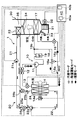
- the outdoor heat exchanger 14 of the present embodiment is arranged so as to exchange heat between the refrigerant circulating inside and the outside air blown from the blower fan 14a and passed through the radiator 24. That is, the outdoor heat exchanger 14 is disposed downstream of the radiator 24 in the flow of the outside air blown from the blower fan 14a.
- Other configurations and operations of the heat pump system 1 are the same as those in the first embodiment.
- the heat of the cooling water flowing through the radiator 24 is indirectly transmitted through the outside air.
- heat can be transferred to the refrigerant flowing through the outdoor heat exchanger 14. Therefore, in the dehumidifying heating mode, the waste heat of the inverter Inv absorbed by the cooling water can be effectively used as a heat source for reheating the dehumidified blown air.
- the heat of the cooling water circulating in the heat medium circuit 20 is effectively used as a heat source for heating the blown air, regardless of the operating state of the inverter Inv. And can be used for suppressing frost formation of the outdoor heat exchanger 14. Further, in the heating end mode, similarly to the first embodiment, the heat of the cooling water circulating through the heat medium circulation circuit 20 is used for defrosting the outdoor heat exchanger 14 regardless of the operating state of the inverter Inv. Can be used.
- the outdoor heat exchanger 14 and the radiator 24 are configured by separate heat exchangers, defrosting or attachment of the outdoor heat exchanger 14 can be performed without using a complicated heat exchanger. Suppression of frost can be easily realized.
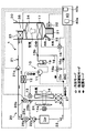
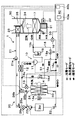
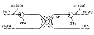
- a heat medium circuit 20 (specifically, the low-pressure side heat medium circuit 22) is used instead of the radiator 24.
- a low-temperature side water-refrigerant heat exchanger 27 that exchanges heat between circulating cooling water and low-pressure refrigerant (specifically, refrigerant flowing out of the outdoor heat exchanger 14) will be described.
- the basic configuration of the low temperature side water-refrigerant heat exchanger 27 is the same as that of the high temperature side water-refrigerant heat exchanger 12. Further, in the present embodiment, the low-temperature side water-refrigerant heat exchanger 27 constitutes a heat exchanger for radiating heat medium that exchanges heat between the cooling water flowing out from the heater core 23 and the low-pressure refrigerant.
- the structure of the other heat pump system 1 is the same as that of 1st Embodiment.
- the operation in the heating end mode is not performed.
- Other operations of the heat pump system 1 are the same as those in the first embodiment. Therefore, even if the heat pump system 1 of the present embodiment is operated, cooling, dehumidifying heating and heating in the passenger compartment can be performed, and the same effect as in the first embodiment can be obtained.
- the low-temperature refrigerant absorbs the heat of the cooling water flowing through the low-temperature side water-refrigerant heat exchanger 27 in the low-temperature side water-refrigerant heat exchanger 27. Can do. Therefore, in the dehumidifying heating mode, the waste heat of the inverter Inv absorbed by the cooling water can be effectively used as a heat source for reheating the dehumidified blown air.
- the heat of the cooling water circulating in the heat medium circuit 20 is effectively used as a heat source for heating the blown air, regardless of the operating state of the inverter Inv. And can be used for suppressing frost formation of the outdoor heat exchanger 14.
- the cooling water flowing out from the inverter Inv is heat-exchanged with the low-pressure refrigerant flowing out from the outdoor heat exchanger 14.
- Heat exchange with the circulating low-pressure refrigerant may be performed.
- the cooling water flowing out from the inverter Inv may be heat-exchanged with the low-pressure refrigerant flowing through the refrigerant flow path from the outlet side of the heating expansion valve 13 to the refrigerant inlet side of the outdoor heat exchanger 14.
- the compressor 11a two compression mechanisms, a low-stage compression mechanism and a high-stage compression mechanism, are provided inside a housing that forms the outer shell thereof, and A two-stage booster type electric compressor configured to accommodate an electric motor that rotationally drives both compression mechanisms is employed.
- An intermediate pressure suction port is provided for allowing the intermediate pressure refrigerant generated in the cycle from the outside to join the refrigerant in the compression process from low pressure to high pressure.
- the intermediate pressure suction port is connected to the refrigerant discharge port side of the low-stage compression mechanism (that is, the refrigerant suction port side of the high-stage compression mechanism).
- Various types such as a scroll type compression mechanism, a vane type compression mechanism, and a rolling piston type compression mechanism can be adopted as the low stage side compression mechanism and the high stage side compression mechanism, respectively.
- the compressor 11a which accommodated two compression mechanisms in one housing is employ
- adopted the format of a compressor is not limited to this. That is, if the intermediate pressure refrigerant can be introduced from the intermediate pressure suction port and merged with the refrigerant in the compression process from low pressure to high pressure, one fixed capacity type compression mechanism and the compression mechanism are provided inside the housing.
- An electric compressor configured to accommodate an electric motor that rotationally drives the motor may be employed.
- two compressors are connected in series, and the suction port of the low-stage compressor disposed on the low-stage side serves as the suction port of the entire two-stage booster compressor, and is disposed on the high-stage side.
- the discharge port of the high-stage compressor is the discharge port of the entire two-stage booster compressor, and the intermediate pressure is applied to the connection that connects the discharge port of the low-stage compressor and the suction port of the high-stage compressor.
- One two-stage booster compressor may be configured by providing two suction ports, ie, a low-stage compressor and a high-stage compressor.
- the refrigerant inlet of the gas-liquid separator 28, which is a gas-liquid separator that separates the gas-liquid of the refrigerant flowing out of the heating expansion valve 13, is connected to the outlet side of the heating expansion valve 13. ing.
- the gas-liquid separator 28 employs a centrifugal separation type that separates the gas-liquid refrigerant by the action of centrifugal force generated by swirling the refrigerant flowing into the internal space of the cylindrical main body. is doing. Furthermore, the internal volume of the gas-liquid separator 28 is a volume that cannot substantially store surplus refrigerant even if a load fluctuation occurs in the cycle and the refrigerant circulation flow rate circulating in the cycle fluctuates.
- the intermediate pressure suction port of the compressor 11 a is connected to the gas-phase refrigerant outlet of the gas-liquid separator 28. Further, a gas phase refrigerant passage opening / closing valve 18b for opening and closing the refrigerant passage is disposed in the refrigerant passage connecting the gas phase refrigerant outlet of the gas-liquid separator 28 and the intermediate pressure suction port of the compressor 11a.
- the basic configuration of the gas-phase refrigerant passage opening / closing valve 18b is the same as that of the heating opening / closing valve 18a.
- the air-conditioning control device 40 opens the gas-phase refrigerant passage opening / closing valve 18b, the gas-phase refrigerant flowing out from the gas-phase refrigerant outlet of the gas-liquid separator 28 moves to the intermediate pressure inlet side of the compressor 11a.
- the refrigerant circuit is switched to and the gas-phase refrigerant passage opening / closing valve 18b is closed, the refrigerant circuit is switched to a refrigerant circuit that does not allow the refrigerant to flow out from the gas-phase refrigerant outlet of the gas-liquid separator 28. Therefore, the gas-phase refrigerant passage opening / closing valve 18b constitutes a refrigerant circuit switching unit.
- the liquid-phase refrigerant outlet of the gas-liquid separator 28 is connected to the inlet side of an intermediate pressure fixed throttle 29 as a pressure reducing device that depressurizes the liquid-phase refrigerant separated by the gas-liquid separator 28.
- an intermediate pressure fixed throttle 29 As the intermediate pressure fixed throttle 29, a nozzle, an orifice, a capillary tube or the like having a fixed throttle opening can be employed.
- the refrigerant inlet side of the outdoor heat exchanger 14 is connected to the outlet side of the intermediate pressure fixed throttle 29.
- the liquid-phase refrigerant separated by the gas-liquid separator 28 is led to the refrigerant inlet side of the outdoor heat exchanger 14 by bypassing the intermediate pressure fixed throttle 29.
- a fixed throttle bypass passage 29a is connected.
- a bypass passage opening / closing valve 18c for opening and closing the fixed throttle bypass passage 29a is disposed in the fixed throttle bypass passage 29a.
- the basic configuration of the bypass passage opening / closing valve 18c is the same as that of the gas-phase refrigerant passage opening / closing valve 18b.
- the pressure loss that occurs when the refrigerant passes through the bypass passage opening / closing valve 18 c is extremely small compared to the pressure loss that occurs when the refrigerant passes through the intermediate pressure fixed throttle 29. Therefore, when the air conditioning control device 40 opens the bypass passage opening / closing valve 18c, the liquid-phase refrigerant that has flowed out of the gas-liquid separator 28 flows into the outdoor heat exchanger 14 through the fixed throttle bypass passage 29a. On the other hand, when the air-conditioning control device 40 closes the bypass passage opening / closing valve 18c, the outdoor heat exchanger 14 after the liquid refrigerant at the entire flow rate flowing out from the gas-liquid separator 28 is depressurized by the intermediate pressure fixed throttle 29. Flow into.
- a refrigerant pipe extending from the liquid-phase refrigerant outlet of the gas-liquid separator 28 to the refrigerant inlet side of the outdoor heat exchanger 14 is provided. You may arrange
- the structure of the other heat pump system 1 is the same as that of 1st Embodiment.
- the operation of the heat pump system 1 of the present embodiment having the above configuration will be described. Also in the heat pump system 1 of the present embodiment, the operations in the cooling mode, the dehumidifying heating mode, the heating mode, and the heating end mode can be performed as in the first embodiment. The operation in each operation mode will be described below.
- Cooling mode In the cooling mode of the present embodiment, the air conditioning control device 40 operates the high-temperature side water pump 21a and the low-temperature side water pump 22a so as to exhibit a predetermined water pressure-feeding capacity.
- the cooling water flow rate adjustment valves 26a and 26b are fully closed.
- the bypass flow rate becomes 0 as in the first embodiment, so that the cooling water circulating in the high-pressure side heat medium circulation circuit 21 and the low-pressure side heat medium circulation circuit 22 are changed.
- the circulating cooling water does not mix and the cooling water circulates through each heat medium circulation circuit.
- the air conditioning control device 40 fully opens the heating expansion valve 13, sets the cooling expansion valve 16 in a throttle state, closes the heating on-off valve 18a, closes the gas-phase refrigerant passage on-off valve 18b, and bypasses the on-off passage on-off valve 18c. open.
- a refrigeration cycle in which the refrigerant circulates in the same order as in the cooling mode of the first embodiment is configured.
- Other operations are the same as those in the cooling mode of the first embodiment. Therefore, in the cooling mode of the present embodiment, as in the cooling mode of the first embodiment, the vehicle interior can be cooled and the inverter Inv can be cooled.
- (B) Dehumidification heating mode In the dehumidification heating mode of this embodiment, the air-conditioning control device 40 operates the high-temperature side water pump 21a and the low-temperature side water pump 22a so as to exhibit a predetermined water pumping capacity, The second coolant flow rate adjusting valves 26a and 26b are fully closed.
- the bypass flow rate becomes 0, so that the cooling water circulating in the high pressure side heat medium circulation circuit 21 and the cooling water circulating in the low pressure side heat medium circulation circuit 22 are mixed.
- the cooling water circulates through each heat medium circuit.
- the air-conditioning control device 40 sets the heating expansion valve 13 to the throttle state, fully opens the cooling expansion valve 16, closes the heating on-off valve 18a, closes the gas-phase refrigerant passage on-off valve 18b, and bypass path on-off valve 18c. open.
- the compressor 11a ⁇ the high temperature side water-refrigerant heat exchanger 12 ⁇ the heating expansion valve 13 ( ⁇ the gas-liquid separator 28).
- a bypass compression on-off valve 18c), an outdoor heat exchanger 14 ( ⁇ cooling expansion valve 16), an indoor evaporator 17, an accumulator 19, and a compressor 11a are formed in a vapor compression refrigeration cycle in which the refrigerant circulates.
- a refrigeration cycle in which the refrigerant circulates in the same order as in the dehumidifying and heating mode of the first embodiment is configured.
- Other operations are the same as in the dehumidifying and heating mode of the first embodiment. Therefore, in the dehumidifying and heating mode of the present embodiment, as in the dehumidifying and heating mode of the first embodiment, it is possible to perform dehumidifying heating in the passenger compartment and to effectively reheat the blown air with the waste heat of the inverter Inv. Can be used.
- the air-conditioning control device 40 operates the high temperature side water pump 21a and the low temperature side water pump 22a so as to exhibit a predetermined water pumping capacity, and the first and second The cooling water flow rate adjusting valves 26a and 26b are opened.
- the cooling water not only circulates through the respective heat medium circulation circuits 21 and 22 but also circulates through the high-pressure side heat medium circulation circuit 21 as in the first embodiment.
- a part of the cooling water flows into the low-pressure side heat medium circulation circuit 22, and a part of the cooling water circulating through the low-pressure side heat medium circulation circuit 22 returns to the high-pressure side heat medium circulation circuit 21.
- the air conditioning control device 40 sets the heating expansion valve 13 to the throttle state, fully closes the cooling expansion valve 16, opens the heating on-off valve 18 a, opens the gas-phase refrigerant passage on-off valve 18 b, and bypasses the bypass passage on-off valve. Close 18c.
- the compressor 11a ⁇ the high-temperature side water-refrigerant heat exchanger 12 ⁇ the heating expansion valve 13 ⁇ the gas-liquid separator 28 ⁇ the intermediate pressure is fixed.
- the refrigerant circulates in the order of the throttle 29 ⁇ the outdoor heat exchanger 14 ( ⁇ the accumulator side passage 18) ⁇ the accumulator 19 ⁇ the compressor 11a, and from the gas-phase refrigerant outlet of the gas-liquid separator 28 to the intermediate pressure inlet of the compressor 11a.
- a gas injection cycle in which a gas-phase refrigerant is flowed into is formed. Other operations are the same as those in the heating mode of the first embodiment.
- the high-pressure refrigerant discharged from the compressor 11a flows into the high-temperature side water-refrigerant heat exchanger 12, and the high-pressure side heat medium
- the cooling water circulating in the circulation circuit 21 is heated.
- the cooling water heated by the high temperature side water-refrigerant heat exchanger 12 flows into the heater core 23, whereby the blown air is heated.
- the refrigerant flowing out of the high temperature side water-refrigerant heat exchanger 12 flows into the heating expansion valve 13 and is depressurized until it becomes an intermediate pressure refrigerant.
- the intermediate pressure refrigerant decompressed by the heating expansion valve 13 flows into the gas-liquid separator 28 and is gas-liquid separated.
- the gas-phase refrigerant separated by the gas-liquid separator 28 is sucked from the intermediate pressure suction port of the compressor 11a and discharged from the low-stage compression mechanism because the gas-phase refrigerant passage opening / closing valve 18b is open. It merges with the intermediate pressure refrigerant and is sucked into the high-stage compression mechanism.
- the liquid-phase refrigerant separated by the gas-liquid separator 28 flows from the liquid-phase refrigerant outlet of the gas-liquid separator 28 to the intermediate pressure fixed throttle 29 side because the bypass passage opening / closing valve 18c is closed.
- the pressure is reduced by the intermediate pressure fixed throttle 29 until low pressure refrigerant is obtained.
- the refrigerant that has flowed out of the intermediate pressure fixed throttle 29 flows into the outdoor heat exchanger 14, is blown from the blower fan 14a, absorbs heat from the outside air after passing through the radiator 24, and evaporates.
- the refrigerant circulating in the low-pressure side heat medium circulation circuit 22 exchanges heat with the outside air blown from the blower fan 14a to radiate heat.
- the subsequent operation of the heat pump cycle 10a is the same as in the first embodiment.
- the vehicle interior can be heated by blowing the blown air heated by the heater core 23 into the vehicle interior, as in the heating mode of the first embodiment, and the inverter
- the waste heat of Inv can be effectively used as a heat source for heating the blown air.
- the refrigerant evaporating temperature in the outdoor heat exchanger 14 is increased to suppress frost formation in the outdoor heat exchanger 14 regardless of the operating state of the inverter Inv that is an external heat source. it can.
- the refrigerant in the heating mode, the refrigerant is boosted in multiple stages, and the intermediate pressure refrigerant generated in the cycle is merged with the refrigerant discharged from the low-stage compression mechanism. It is switched to a refrigerant circuit that constitutes a gas injection cycle to be sucked into the side compression mechanism. Thereby, the mechanical efficiency (compression efficiency) of the compressor 11a can be improved and COP can be improved.
- (D) Heating end mode In the heating end mode of the present embodiment, the air conditioning control device 40 stops the compressor 11a and the blower 32. Further, the air conditioning control device 40 operates the high temperature side water pump 21a and the low temperature side water pump 22a so as to exhibit a predetermined water pressure feeding capacity, and fully opens the first and second cooling water flow rate adjustment valves 26a, 26b. To do. Other operations are the same as those in the heating end mode of the first embodiment.
- an inverter that is an external heat source Regardless of the operating state of Inv, this can be defrosted by the heat of the cooling water flowing through the radiator 24.
- the heat pump cycle 10a described in the fourth embodiment is adopted as shown in the overall configuration diagram of FIG. 8 in contrast to the second embodiment.
- Other configurations and operations of the heat pump system 1 are the same as those in the second embodiment. Therefore, even if the heat pump system 1 of this embodiment is operated, the cooling, dehumidifying heating and heating in the passenger compartment can be performed, and the same effects as those of the second embodiment can be obtained. Furthermore, in the heating mode, it is possible to obtain the COP improvement effect by configuring the gas injection cycle.
- the heat pump cycle 10a described in the fourth embodiment is adopted as shown in the overall configuration diagram of FIG. 9 with respect to the third embodiment.
- Other configurations and operations of the heat pump system 1 are the same as those in the third embodiment. Therefore, even if the heat pump system 1 of the present embodiment is operated, cooling, dehumidifying heating and heating in the passenger compartment can be performed, and the same effect as that of the third embodiment can be obtained. Furthermore, in the heating mode, it is possible to obtain the COP improvement effect by configuring the gas injection cycle.
- the inverter Inv that is an external heat source is not connected to the low-pressure side heat medium circulation circuit 22 in the first embodiment.
- Other configurations and operations are the same as those in the first embodiment.
- the defrosting or frosting suppression of the outdoor heat exchanger 14 is realized without depending on the heat supplied from an external heat source or the like. Can do. Therefore, even if the inverter Inv is eliminated as in the heat pump system 1 of the present embodiment, the same effect as that of the first embodiment can be obtained.
- the inverter Inv as an external heat source is not connected to the low-pressure side heat medium circulation circuit 22 as shown in the overall configuration diagram of FIG.
- Other configurations and operations are the same as those of the second embodiment. Therefore, according to the heat pump system 1 of this embodiment, the same effect as 2nd Embodiment can be acquired.
- the inverter Inv which is an external heat source, is not connected to the low-pressure side heat medium circuit 22 as shown in the overall configuration diagram of FIG.
- Other configurations and operations are the same as those of the third embodiment. Therefore, according to the heat pump system 1 of this embodiment, the same effect as 3rd Embodiment can be acquired.
- the heat pump cycle 10 of the present embodiment is provided with a high-pressure side branching portion 15c that branches the flow of the refrigerant flowing out from the refrigerant passage of the high-temperature side water-refrigerant heat exchanger 12.
- the basic configuration of the high-pressure branch 15c is the same as that of the low-pressure branch 15a.
- the inlet side of the heating expansion valve 13 is connected to one refrigerant outlet of the high pressure side branch 15c, and the inlet side of the outdoor unit bypass passage 51 is connected to the other refrigerant outlet of the high pressure side branch 15c. Yes.
- the outdoor unit bypass passage 51 bypasses the refrigerant branched at the high-pressure side branch portion 15c, bypasses the heating expansion valve 13 and the outdoor heat exchanger 14, and guides the refrigerant to the upstream side of the refrigerant flow of the cooling expansion valve 16. It is. Further, an outdoor unit bypass passage opening / closing valve 18 d for opening and closing the outdoor unit bypass passage 51 is disposed in the outdoor unit bypass passage 51.
- the basic configuration of the bypass passage opening / closing valve 18c is the same as that of the heating opening / closing valve 18a and the like, and constitutes the refrigerant circuit switching unit in the present embodiment.
- the structure of the other heat pump system 1 is the same as that of 1st Embodiment.
- the operation of the heat pump system 1 of the present embodiment having the above configuration will be described. Also in the heat pump system 1 of the present embodiment, the operations in the cooling mode, the dehumidifying heating mode, the heating mode, and the heating end mode can be performed as in the first embodiment. The operation in each operation mode will be described below.
- the air conditioning control device 40 operates the high-temperature side water pump 21a and the low-temperature side water pump 22a so as to exhibit a predetermined water pressure-feeding capacity.
- the cooling water flow rate adjustment valves 26a and 26b are fully closed. Further, the air-conditioning control device 40 fully opens the heating expansion valve 13, sets the cooling expansion valve 16 in the throttle state, closes the heating on-off valve 18a, and closes the outdoor unit bypass passage on-off valve 18d.
- the cooling water circulates in the same manner as in the dehumidifying heating mode of the first embodiment.
- the heat pump cycle 10 in the cooling mode as shown by the white arrows in FIG.
- a vapor compression refrigeration cycle in which the refrigerant circulates is configured in exactly the same manner as in the first embodiment. Other operations are the same as those in the cooling mode of the first embodiment.
- the vehicle interior can be cooled and the inverter Inv can be cooled as in the cooling mode of the first embodiment.
- (B) Dehumidification heating mode In the cooling mode of the present embodiment, the air conditioning control device 40 operates the high temperature side water pump 21a and the low temperature side water pump 22a so as to exhibit a predetermined water pumping capacity, and the first and first 2.
- the cooling water flow rate adjustment valves 26a and 26b are fully closed.
- the bypass flow rate becomes 0, so that the cooling water circulating in the high pressure side heat medium circulation circuit 21 and the cooling water circulating in the low pressure side heat medium circulation circuit 22 are mixed.
- the cooling water circulates through each heat medium circuit.
- the air-conditioning control device 40 sets the heating expansion valve 13 to the throttle state, sets the cooling expansion valve 16 to the throttle state, closes the heating on-off valve 18a, and opens the outdoor unit bypass passage on-off valve 18d.
- the compressor 11 ⁇ the high-temperature side water-refrigerant heat exchanger 12 ⁇ the heating expansion valve 13 ⁇ the outdoor heat exchanger 14 ( ⁇ Accumulator side passage 18) ⁇ Accumulator 19 ⁇
- Compressor 11 circulates refrigerant in this order, and high temperature side water-refrigerant heat exchanger 12 ( ⁇ outdoor bypass path 51) ⁇ cooling expansion valve 16 ⁇ indoor evaporator 17 ⁇
- a vapor compression refrigeration cycle in which the refrigerant circulates in the order of the accumulator 19 is configured.
- the outdoor heat exchanger 14 and the indoor evaporator 17 are connected in parallel to the refrigerant flow.
- the air conditioning control device 40 is configured so that the throttle opening degree of the heating expansion valve 13 and the cooling expansion valve 16 becomes a predetermined opening degree for dehumidifying heating.
- the control signals output to the heating expansion valve 13 and the cooling expansion valve 16 are determined. Other operations are the same as in the dehumidifying and heating mode of the first embodiment.
- the high-pressure refrigerant discharged from the compressor 11 flows into the high-temperature side water-refrigerant heat exchanger 12 and the high-pressure side heat.
- the cooling water circulating through the medium circulation circuit 21 is heated.
- the cooling water heated by the high temperature side water-refrigerant heat exchanger 12 flows into the heater core 23, whereby the blown air is heated.
- the flow of the refrigerant flowing out of the high temperature side water-refrigerant heat exchanger 12 is branched at the high pressure side branching portion 15c.
- One refrigerant branched by the high pressure side branching portion 15 c is decompressed by the heating expansion valve 13 until it becomes a low pressure refrigerant, and flows into the outdoor heat exchanger 14.
- the refrigerant flowing into the outdoor heat exchanger 14 is blown by the outdoor heat exchanger 14 from the blower fan 14a and absorbs heat from the outside air after passing through the radiator 24 to evaporate.
- the refrigerant circulating in the low-pressure side heat medium circulation circuit 22 exchanges heat with the outside air blown from the blower fan 14a to radiate heat.
- the heating on-off valve 18a Since the heating on-off valve 18a is open, the refrigerant flowing out of the outdoor heat exchanger 14 flows into the accumulator 19 through the low pressure side branching portion 15a, the accumulator side passage 18 and the merging portion 15b, and is separated into gas and liquid. . Under the present circumstances, the refrigerant
- the other refrigerant branched by the high pressure side branching portion 15 c is decompressed by the cooling expansion valve 16 until it becomes a low pressure refrigerant, and flows into the indoor evaporator 17.
- the refrigerant flowing into the indoor evaporator 17 absorbs heat from the blown air blown from the blower 32 and evaporates in the indoor evaporator 17. Thereby, blowing air is cooled.
- the refrigerant that has flowed out of the indoor evaporator 17 flows into the accumulator 19 through the junction 15b.
- the air blown after being dehumidified by being cooled by the indoor evaporator 17 is reheated by the heater core 23 and blown out into the vehicle interior, thereby performing dehumidification heating in the vehicle interior.
- the inverter Inv can be cooled by dissipating the heat absorbed by the refrigerant circulating in the low-pressure side heat medium circuit 22 from the inverter Inv to the outside air or the like by the radiator 24.
- the outdoor heat exchanger 14 and the indoor evaporator 17 are connected in parallel to the refrigerant flow, so that the refrigerant evaporation temperature in the outdoor heat exchanger 14 is set to the indoor evaporator.
- the refrigerant evaporating temperature in 17 can be lowered.
- the refrigerant evaporation temperature in the outdoor heat exchanger 14 is set as the reference frost formation.
- the amount of heat absorbed by the refrigerant in the outdoor heat exchanger 14 can be increased by lowering the temperature below the prevention temperature.
- the outdoor heat exchanger 14 and the indoor evaporator 17 are connected in series with respect to the refrigerant flow in this order, and the refrigerant evaporation temperature in the outdoor heat exchanger 14 is indoor evaporated.
- the heating capacity of the blown air can be increased.
- the air-conditioning control device 40 operates the high temperature side water pump 21a and the low temperature side water pump 22a so as to exhibit a predetermined water pumping capacity, and the first and second The cooling water flow rate adjusting valves 26a and 26b are opened. Furthermore, the air-conditioning control device 40 places the heating expansion valve 13 in the throttle state, fully closes the cooling expansion valve 16, opens the heating on-off valve 18a, and closes the outdoor unit bypass passage on-off valve 18d.
- the cooling water circulates similarly to the heating mode in the first embodiment, and in the heat pump cycle 10 in the cooling mode, as shown by the black arrows in FIG.
- a vapor compression refrigeration cycle in which the refrigerant circulates is configured just like the embodiment. Other operations are the same as those in the heating mode of the first embodiment.
- the vehicle interior can be heated as in the heating mode of the first embodiment, and the waste heat of the inverter Inv is effectively used as a heat source for heating the blown air. Can be used.
- the refrigerant evaporating temperature in the outdoor heat exchanger 14 is increased to suppress frost formation in the outdoor heat exchanger 14 regardless of the operating state of the inverter Inv that is an external heat source. it can.
- (D) Heating end mode In the heating end mode of the present embodiment, the air conditioning control device 40 stops the compressor 11 and the blower 32. Further, the air conditioning control device 40 operates the high temperature side water pump 21a and the low temperature side water pump 22a so as to exhibit a predetermined water pressure feeding capacity, and fully opens the first and second cooling water flow rate adjustment valves 26a, 26b. To do. Other operations are the same as those in the heating end mode of the first embodiment.
- an inverter that is an external heat source Regardless of the operating state of Inv, this can be defrosted by the heat of the cooling water flowing through the radiator 24.
- a high pressure side branching portion 15c, an outdoor unit bypass passage 51, and a bypass passage opening / closing valve 18c are added to the second embodiment.
- the structure of the other heat pump system 1 is the same as that of 2nd Embodiment.
- the outdoor unit bypass passage opening / closing valve 18d can be closed to operate in the same manner as in the second embodiment, and the same effect as in the second embodiment can be obtained.
- the heating ability of the blown air can be improved as in the tenth embodiment.
- a high pressure side branching portion 15c, an outdoor unit bypass passage 51, and a bypass passage opening / closing valve 18c are added to the third embodiment as shown in the overall configuration diagram of FIG.
- the structure of the other heat pump system 1 is the same as that of 3rd Embodiment.
- the outdoor unit bypass passage opening / closing valve 18d can be closed to operate in the same manner as in the third embodiment, and the same effect as in the third embodiment can be obtained.
- the heating ability of the blown air can be improved as in the tenth embodiment.
- the present invention may be applied to an electric vehicle (including a fuel cell vehicle) that obtains a driving force for driving a vehicle from an electric motor for driving the vehicle, or an air conditioner for a normal vehicle that obtains a driving force for driving the vehicle from an engine.
- the heat pump system 1 according to the present disclosure is not limited to a vehicle, and may be applied to a stationary air conditioner, a cold storage, a liquid heating / cooling device, and the like.
- the inverter Inv is used as an in-vehicle device (external heat source) that generates heat during operation
- the external heat source is not limited to this.
- an electric device such as an engine or a traveling electric motor can be used as an external heat source.
- first and second cooling water flow rate adjusting valves 26a and 26b are employed as the heat medium flow rate adjusting device
- the heat medium flow rate adjusting device is not limited thereto.
- one of the first and second cooling water flow rate adjustment valves 26a and 26b may be an open / close valve that opens and closes the connection flow path. Then, when the other flow rate adjustment valve opens the connection flow path, the opening / closing valve may be controlled to open.
- the flow rate for circulating the high-pressure side heat medium circulation circuit 21 at the connection portion between the high-pressure side heat medium circulation circuit 21 and the first connection flow path 25a and the low-pressure side heat medium circulation from the high-pressure side heat medium circulation circuit 21 is arranged.
- a first type 3 flow rate adjusting valve that adjusts the flow rate ratio with the bypass flow rate to flow out to the circuit 22 is arranged.
- a second three-type flow rate adjustment valve that adjusts the flow rate ratio with the bypass flow rate to be returned is arranged. And you may comprise a heat carrier flow control apparatus by these 1st, 2nd 3 system flow control valves.
- heat is generated by the first and second three-way valves 50a and 50b as shown in the schematic diagram of the heat medium circulation circuit 20 in FIG.
- a medium flow rate adjusting device may be configured.
- the first three-way valve 50a is disposed at a connection portion between the high-pressure side heat medium circulation circuit 21 and the first connection flow path 25a, and is a discharge port of the high-temperature side water pump 21a.
- the second three-way valve 50b is disposed at a connection portion between the low-pressure side heat medium circulation circuit 22 and the second connection channel 25b, and connects the cooling water outlet side of the radiator 24 and the suction port side of the low-temperature side water pump 22a. And the function of switching the circuit connecting the cooling water outlet side of the radiator 24 and the cooling water inlet side of the high-temperature side water-refrigerant heat exchanger 12.
- a first check valve 51a that allows only cooling water to flow from the high-pressure side heat medium circulation circuit 21 side to the low-pressure side heat medium circulation circuit 22 side is disposed in the first connection flow path 25a.
- a second check valve 51b that only allows cooling water to flow from the low-pressure side heat medium circulation circuit 22 side to the high-pressure side heat medium circulation circuit 21 side is disposed in the connection flow path 25b.
- the first three-way valve 50a connects the discharge port side of the high temperature side water pump 21a and the cooling water inlet side of the high temperature side water-refrigerant heat exchanger 12, and 2
- the three-way valve 50b switches to a circuit that connects the cooling water outlet side of the radiator 24 and the suction port side of the low temperature side water pump 22a, so that the cooling water circulating in the high pressure side heat medium circulation circuit 21 and the low pressure side heat medium circulation
- a heat medium circulation circuit in which the cooling water circulating in the circuit 22 is not mixed can be configured.
- the first three-way valve 50a connects the discharge port side of the high temperature side water pump 21a and the suction port side of the low temperature side water pump 22a as shown by the thick broken line arrow in FIG.
- the total flow rate of the cooling water can be increased by the high pressure side heat medium circulation circuit 21 and the low pressure side heat medium.
- a heat medium circulation circuit that circulates both circulation circuits 22 can be configured.
- the four-way valve 52 connects the discharge port side of the high temperature side water pump 21a and the cooling water inlet side of the high temperature side water-refrigerant heat exchanger 12 and at the same time the cooling water outlet side and low temperature side water of the radiator 24.
- the four-way valve 52 switches the cooling water circuit as indicated by the thick solid arrow in FIG. 17, the cooling water circulating through the high-pressure side heat medium circulation circuit 21 and the cooling water circulating through the low-pressure side heat medium circulation circuit 22 are changed.
- a heat medium circulation circuit that does not mix can be configured.
- the four-way valve 52 switches the cooling water circuit as shown by the thick broken line arrows in FIG. 17 so that the total flow rate of the cooling water circulates in both the high-pressure side heat medium circulation circuit 21 and the low-pressure side heat medium circulation circuit 22.
- a heat medium circulation circuit can be configured.
- compressors 11 and 11a are not limited thereto.
- an engine-driven compressor driven by a rotational driving force transmitted from an internal combustion engine (engine) via a pulley, a belt, or the like may be employed as the compressor.
- This type of engine-driven compressor is a variable capacity compressor that can adjust the refrigerant discharge capacity by changing the discharge capacity.
- the refrigerant discharge capacity can be increased by changing the operating rate of the compressor by switching the electromagnetic clutch.
- a fixed capacity compressor to be adjusted can be employed.
- the example in which the outdoor heat exchanger 14 and the radiator 24 are integrated as the heat exchanger structure 60 has been described.
- the refrigerant that flows through the outdoor heat exchanger 14 and the cooling water that flows through the radiator 24 are described.
- the integration of the outdoor heat exchanger 14 and the radiator 24 is not limited thereto.
- the refrigerant tubes 14a and the heat medium tubes 24a are alternately stacked, and an air passage through which the outside air blown from the blower fan 14a is circulated between the adjacent refrigerant tubes 14a and the heat medium tubes 24a.
- the outdoor heat exchanger 14 and the radiator 24 may be integrated by arrange
- the number of the refrigerant tubes 14a and the number of the heat medium tubes 24a may be different.
- bypass passage opening / closing valve 18c an example in which the bypass passage opening / closing valve 18c is used has been described.
- the liquid-phase refrigerant outlet and the intermediate pressure fixed throttle of the gas-liquid separator 28 are used instead of the bypass passage opening / closing valve 18c.
- An electric three-way valve that switches between a refrigerant circuit that connects the 29 inlet side and a refrigerant circuit that connects the liquid phase refrigerant outlet of the gas-liquid separator 28 and the fixed throttle bypass passage 29a inlet side may be adopted. .
- the air conditioning control device 40 sets the heating expansion valve 13 to the throttle state, fully opens the cooling expansion valve 16, and further sets the blown air temperature TAV to the target.
- control at the time of dehumidification heating mode is not limited to this.
- the air conditioning control device 40 controls the opening degree of the air mix door 34 so that the air passage on the heater core 23 side is fully opened, and further, as the target blowing temperature TAO rises, the throttle of the heating expansion valve 13 is controlled. Control may be performed such that the opening degree is gradually decreased and the throttle opening degree of the cooling expansion valve 16 is gradually increased.
- the outdoor heat exchanger 14 can be switched from the refrigerant circuit functioning as a radiator to the refrigerant circuit functioning as an evaporator as the target blowing temperature TAO increases. More specifically, in the refrigerant circuit in which the outdoor heat exchanger 14 functions as a radiator, the amount of heat released from the refrigerant in the outdoor heat exchanger 14 is gradually reduced as the target blowout temperature TAO rises, and the evaporator circuit changes to the evaporator. In the refrigerant circuit functioning as, the heat absorption amount of the refrigerant in the outdoor heat exchanger 14 can be gradually increased as the target blowing temperature TAO increases.
- the amount of heat released from the refrigerant in the high temperature side water-refrigerant heat exchanger 12 can be gradually increased as the target blowing temperature TAO rises, and the cooling heated by the high temperature side water-refrigerant heat exchanger 12 can be achieved.
- the temperature of water can be raised and the temperature of blowing air can be raised.
- the air conditioning control device 40 opens the outdoor unit bypass passage opening / closing valve 18d, so that the outdoor heat exchanger 14 and the indoor evaporator 17 are protected from the refrigerant flow.
- the control in the dehumidifying and heating mode is not limited to this.
- two operation modes of the first and second dehumidifying and heating modes are provided, and in the first dehumidifying and heating mode, the air conditioning control device 40 closes the outdoor unit bypass passage opening / closing valve 18d, whereby the outdoor heat exchanger 14 and the indoor evaporation are performed. Switch to a refrigerant circuit in which the vessel 17 is connected in series. Further, in the second dehumidifying and heating mode, the air conditioning controller 40 opens the outdoor unit bypass passage opening / closing valve 18d, thereby switching to the refrigerant circuit in which the outdoor heat exchanger 14 and the indoor evaporator 17 are connected in parallel.
- the bypass flow rate of the cooling water flowing from the high pressure side heat medium circulation circuit 21 to the low pressure side heat medium circulation circuit 22 (that is, the low pressure side heat)
- the operation of the heat medium flow control devices is controlled so that the coolant bypass flow rate returning from the medium circulation circuit 22 to the high-pressure side heat medium circulation circuit 21 decreases. May be.
- the temperature rise of the heating target fluid (blast air) can be prioritized with respect to the suppression of frost formation in the outdoor heat exchanger 14, for example, the blown air is quickly heated immediately after the start of the heating mode. Instant heating can be realized.
- the temperature for detecting the temperature of the cooling water flowing out from the cooling water passage provided in the inverter Inv that is an external heat source A detector (cooling water temperature sensor) is provided, and the temperature Tw of the cooling water detected by the temperature detector is determined as a reference heat medium temperature KTw determined for suppressing frost formation or defrosting of the outdoor heat exchanger 14. When it becomes below, you may make a bypass flow rate increase.
- the frost formation of the outdoor heat exchanger 14 or the defrosting can be more reliably performed regardless of the operation modes such as the cooling mode, the dehumidifying heating mode, and the heating mode. Further, when the outdoor unit temperature Ts detected by the outdoor heat exchanger temperature sensor is 0 ° C. or lower and the cooling water temperature Tw is lower than the reference heat medium temperature KTw, the bypass flow rate is increased. You may be allowed to.
- the heat that is not used to heat the blown air that is the fluid to be heated out of the heat of the cooling water is frosted by the outdoor heat exchanger 14. It may be used positively for suppression or defrosting.
- the bypass flow rate may be increased when the blown air temperature TAV becomes equal to or higher than the target blowout temperature TAO.
- the occupant turns off the auto switch on the operation panel during the execution of the heating mode.
- the outdoor temperature Ts detected by the outdoor heat exchanger temperature sensor is 0 ° C. or lower when the occupant turns off the auto switch of the operation panel during the execution of the heating mode, You may make it perform heating completion mode until it becomes high temperature.
- heating of the blown air by the heat pump cycle 10 is stopped in synchronization with the operation state of the engine, and the operation in the heating end mode is performed in accordance with this stop. You may make it perform. Further, when the vehicle is parked or stopped, the driving in the heating end mode may be executed.
- the inverter Inv is connected to the low-pressure side heat medium circuit 22 as described in the seventh to ninth embodiments. It is good also as a structure which is not. Further, as described in the tenth to twelfth embodiments, the high pressure side branch portion 15c, the outdoor unit bypass passage 51, and the bypass passage opening / closing valve 18c may be added.
Abstract
ヒートポンプサイクル(10)にて加熱された冷却水を循環させる高圧側熱媒体循環回路(21)に、冷却水と車室内へ送風される送風空気とを熱交換させるヒータコア(23)を配置し、高圧側熱媒体循環回路(21)に連結された低圧側熱媒体循環回路(22)に、ヒータコア(23)から流出した冷却水の少なくとも一部とヒートポンプサイクル(10)の低圧冷媒とを熱交換させるラジエータ(24)を配置する。これにより、ヒータコア(23)から流出した冷却水の有する送風空気を加熱するために利用されなかった余剰の熱によって、室外熱交換器(14)の着霜を抑制でき、室外熱交換器(14)に着いた霜を除霜することができる。
Description
本出願は、当該開示内容が参照によって本出願に組み込まれた、2013年11月25日に出願された日本特許出願2013-242521を基にしている。
本開示は、ヒートポンプサイクルによって加熱対象流体を加熱するヒートポンプシステムに関する。
従来、ヒートポンプサイクル(蒸気圧縮式の冷凍サイクル)によって加熱対象流体を加熱するヒートポンプシステムが知られている。この種のシステムに適用されるヒートポンプサイクルでは、低圧冷媒を外気と熱交換させて蒸発させる蒸発器として機能する室外熱交換器における冷媒蒸発温度が0℃以下に低下すると、室外熱交換器に着霜が生じてしまうことがある。
さらに、このように生じた室外熱交換器の着霜を取り除く手段として、ヒートポンプサイクルの圧縮機から吐出された高温高圧冷媒(ホットガス)を、室外熱交換器へ流入させることによって除霜する、いわゆるホットガス除霜も知られている。ところが、このホットガス除霜では、除霜時間が比較的長くなってしまい、除霜のために圧縮機が消費するエネルギが増大してしまう。
これに対して、特許文献1には、車両用空調装置に適用されたヒートポンプシステムであって、車載電気機器を冷却する冷却水に蓄熱された廃熱を熱源として、着霜が生じた室外熱交換器の除霜を行うものが開示されている。この特許文献1のヒートポンプシステムでは、車載電気機器の廃熱を利用して室外熱交換器の除霜を行っているので、除霜のために圧縮機が消費するエネルギが増大してしまうことを抑制できる。
しかしながら、本願の発明者らの検討によれば、特許文献1のヒートポンプシステムのように、車載電気機器のような外部熱源から供給される熱によって室外熱交換器の除霜を行う構成では、外部熱源の作動状態によっては、除霜に要する熱を充分に確保することができない場合がある。その結果、外部熱源から供給される熱によって、室外熱交換器を適切に除霜することや、室外熱交換器の着霜を抑制することができなくなってしまう。
本開示は、上記点に鑑み、外部から供給される熱によらず、さらに、ヒートポンプサイクルの圧縮機の消費エネルギを増大させることなく、室外熱交換器の除霜あるいは着霜の抑制を実現可能なヒートポンプシステムを提供することを目的とする。
上記目的を達成するために本開示の一態様のヒートポンプシステムは、ヒートポンプサイクルと熱媒体循環回路と熱媒体放熱部とを備える。ヒートポンプサイクルは、冷媒を圧縮して吐出する圧縮機、圧縮機から吐出された高圧冷媒と熱媒体とを熱交換させる熱媒体-冷媒熱交換器、熱媒体-冷媒熱交換器から流出した冷媒を減圧させる減圧装置、および減圧装置にて減圧された冷媒と外気とを熱交換させる室外熱交換器を有する。熱媒体循環回路には、熱媒体を循環させるとともに、熱媒体-冷媒熱交換器から流出した熱媒体と加熱対象流体とを熱交換させて加熱対象流体を加熱する加熱用熱交換器が配置される。さらに、熱媒体放熱部では、加熱用熱交換器から流出した熱媒体の有する熱を減圧装置出口側から圧縮機吸入口へ至る範囲を流通する低圧冷媒に放熱させる。
これによれば、熱媒体放熱部を備えているので、熱媒体循環回路を循環する熱媒体の有する熱を低圧冷媒に放熱させることができる。そして、熱媒体から低圧冷媒に放熱された熱によって、室外熱交換器を除霜することや、室外熱交換器の着霜を抑制することができる。
さらに、熱媒体放熱部では、加熱用熱交換器から流出した熱媒体の有する熱を低圧冷媒に放熱させるので、熱媒体-冷媒熱交換器にて加熱された熱媒体の有する熱を加熱対象流体の加熱のために優先的に利用し、その余剰の熱を室外熱交換器の除霜あるいは着霜の抑制のために利用することができる。従って、圧縮機の消費エネルギを増大させることなく、室外熱交換器の除霜あるいは着霜の抑制を実現することができる。
そのため、外部熱源等から供給される熱に依存することなく、さらに、ヒートポンプサイクルの圧縮機の消費エネルギを増大させることなく、室外熱交換器の除霜あるいは着霜の抑制を実現可能なヒートポンプシステムを提供することができる。
例えば、熱媒体放熱部は、加熱用熱交換器から流出した熱媒体と外気とを熱交換させる熱媒体放熱用熱交換器にて構成されており、熱媒体放熱用熱交換器および室外熱交換器は、熱媒体放熱用熱交換器を流通する熱媒体と室外熱交換器を流通する冷媒との間の熱移動を可能に一体化されてもよい。
これによれば、熱媒体放熱用熱交換器を流通する熱媒体の有する熱を、直接的に室外熱交換器へ伝熱することができ、室外熱交換器の効果的な除霜あるいは効果的な着霜の抑制を実現することができる。
また、熱媒体放熱部は、加熱用熱交換器から流出した熱媒体と外気とを熱交換させる熱媒体放熱用熱交換器にて構成されており、室外熱交換器は、熱媒体放熱用熱交換器から流出した外気と減圧装置にて減圧された冷媒とを熱交換させるように配置されていてもよい。
これによれば、熱媒体放熱用熱交換器を流通する熱媒体の有する熱を、外気を介して間接的に室外熱交換器へ伝熱することができ、室外熱交換器の除霜あるいは着霜の抑制を容易に実現することができる。
また、熱媒体放熱部は、加熱用熱交換器から流出した熱媒体と低圧冷媒とを熱交換させる熱媒体放熱用熱交換器によって構成されていてもよい。
これによれば、熱媒体放熱用熱交換器を流通する熱媒体の有する熱を低圧冷媒に吸熱させることができるので、室外熱交換器における冷媒蒸発温度を上昇させて、着霜の抑制を実現することができる。
さらに、上述した熱媒体放熱用熱交換器を備えるヒートポンプシステムにおいて、加熱用熱交換器から流出して熱媒体放熱用熱交換器へ流入する熱媒体の流量を調整する熱媒体流量調整装置を備えていてもよい。
これによれば、ヒートポンプサイクルに要求される加熱対象流体の加熱能力等に応じて、熱媒体から低圧冷媒に放熱される熱量を適切に調整することができる。
(第1実施形態)
図1~図4により、本開示の第1実施形態について説明する。本実施形態では、本開示に係るヒートポンプシステム1を、内燃機関(エンジン)および走行用電動モータから車両走行用の駆動力を得る、いわゆるハイブリッド車両の車両用空調装置に適用している。本実施形態のヒートポンプシステム1は、車両用空調装置において、空調対象空間である車室内へ送風される送風空気を加熱あるいは冷却する機能を果たす。
図1~図4により、本開示の第1実施形態について説明する。本実施形態では、本開示に係るヒートポンプシステム1を、内燃機関(エンジン)および走行用電動モータから車両走行用の駆動力を得る、いわゆるハイブリッド車両の車両用空調装置に適用している。本実施形態のヒートポンプシステム1は、車両用空調装置において、空調対象空間である車室内へ送風される送風空気を加熱あるいは冷却する機能を果たす。
より具体的には、本実施形態のヒートポンプシステム1は、送風空気を加熱あるいは冷却する蒸気圧縮式の冷凍サイクルであるヒートポンプサイクル10、および熱媒体である冷却水(例えば、エチレングリコール水溶液)を循環させる熱媒体循環回路20を備えている。そして、送風空気を加熱する際には、ヒートポンプサイクル10によって冷却水を加熱し、加熱された冷却水を熱源として送風空気を加熱している。従って、本実施形態のヒートポンプシステム1における加熱対象流体は送風空気である。
さらに、本実施形態のヒートポンプサイクル10は、送風空気を冷却して車室内の冷房を行う冷房モードの冷媒回路、送風空気を加熱して車室内の暖房を行う暖房モードの冷媒回路、冷却して除湿された送風空気を加熱することによって車室内を除湿しながら暖房を行う除湿暖房モードの冷媒回路に切替可能に構成されている。
なお、図1では、冷房モードの冷媒回路における冷媒の流れを白抜き矢印で示し、暖房モードの冷媒回路における冷媒の流れを黒塗り矢印で示し、除湿暖房モードの冷媒回路における冷媒の流れを斜線ハッチング付き矢印で示している。
また、このヒートポンプサイクル10では、冷媒としてHFC系冷媒(具体的には、R134a)を採用しており、サイクルの高圧側冷媒圧力Pdが冷媒の臨界圧力を超えない蒸気圧縮式の亜臨界冷凍サイクルを構成している。もちろん、HFO系冷媒(例えば、R1234yf)等を採用してもよい。さらに、冷媒には圧縮機11を潤滑するための冷凍機油が混入されており、冷凍機油の一部は冷媒とともにサイクルを循環している。
ヒートポンプサイクル10の構成機器のうち、圧縮機11は、エンジンルーム内に配置されて、ヒートポンプサイクル10において冷媒を吸入して高圧冷媒となるまで昇圧して吐出するものである。具体的には、本実施形態の圧縮機11は、1つのハウジング内に固定容量型の圧縮機構、および圧縮機構を駆動する電動モータを収容して構成された電動圧縮機である。
この圧縮機構としては、スクロール型圧縮機構、ベーン型圧縮機構等の各種圧縮機構を採用することができる。また、電動モータは、後述する空調制御装置40から出力される制御信号によって、その作動(回転数)が制御されるもので、交流モータ、直流モータのいずれの形式を採用してもよい。
圧縮機11の吐出口側には、高温側水-冷媒熱交換器12の冷媒通路の冷媒入口側が接続されている。高温側水-冷媒熱交換器12は、圧縮機11から吐出された高圧冷媒と熱媒体循環回路20を循環する冷却水とを熱交換させて、冷却水を加熱する熱媒体-冷媒熱交換器である。
このような高温側水-冷媒熱交換器12としては、高圧冷媒通路として高圧冷媒を流通させる複数本のチューブを設け、隣り合うチューブ間に冷却水を流通させる水通路を形成し、これらの水通路内に冷媒と冷却水との間の熱交換を促進するインナーフィンを配置することによって構成された熱交換器等を採用することができる。
高温側水-冷媒熱交換器12の冷媒通路の出口側には、暖房用膨張弁13の入口側が接続されている。暖房用膨張弁13は、少なくとも暖房モード時に、高温側水-冷媒熱交換器12から流出した高圧冷媒を減圧させる減圧装置であり、絞り開度を変更可能に構成された弁体と、この弁体を変位させて絞り開度を変化させるステッピングモータからなる電動アクチュエータとを有して構成される電気式の可変絞り機構である。
さらに、本実施形態の暖房用膨張弁13は、絞り開度を全開にすることで冷媒減圧作用を殆ど発揮することなく単なる冷媒通路として機能する全開機能付きの可変絞り機構で構成されている。暖房用膨張弁13は、空調制御装置40から出力される制御信号によって、その作動が制御される。
暖房用膨張弁13の出口側には、室外熱交換器14の冷媒入口側が接続されている。室外熱交換器14は、エンジンルーム内の前方側に配置されて、高温側水-冷媒熱交換器12下流側の冷媒と送風ファン14aから送風された外気とを熱交換させる熱交換器である。
より詳細には、室外熱交換器14は、少なくとも冷房モード時には、高圧冷媒を放熱させる放熱器として機能し、少なくとも暖房モード時には、減圧装置である暖房用膨張弁13にて減圧された低圧冷媒を蒸発させて吸熱作用を発揮させる蒸発器として機能する。また、送風ファン14aは、空調制御装置40から出力される制御電圧によって稼働率、すなわち回転数(送風能力)が制御される電動送風機である。
さらに、本実施形態の室外熱交換器14は、後述するラジエータ24と一体的に構成されている。このため、本実施形態の送風ファン14aは、室外熱交換器14およびラジエータ24の双方に向けて外気を送風する機能を果たす。なお、一体化された室外熱交換器14およびラジエータ24(以下、熱交換器構造体60という)の詳細構成については後述する。
室外熱交換器14の冷媒出口側には、室外熱交換器14から流出した冷媒の流れを分岐する低圧側分岐部15aの冷媒流入口が接続されている。低圧側分岐部15aは、三方継手で構成されており、3つの流入出口のうち1つを冷媒流入口とし、残りの2つを冷媒流出口としたものである。このような三方継手は、管径の異なる配管を接合して形成してもよいし、金属ブロックや樹脂ブロックに複数の冷媒通路を設けることによって形成してもよい。
低圧側分岐部15aの一方の冷媒流出口には、逆止弁16aを介して、冷房用膨張弁16の冷媒入口側が接続され、他方の冷媒流出口には、低圧側分岐部15aから流出した冷媒を冷房用膨張弁16等を迂回させて後述するアキュムレータ19の上流側へ導くアキュムレータ側通路18の入口側が接続されている。
逆止弁16aは、低圧側分岐部15aの一方の冷媒流出口から流出した冷媒が、低圧側分岐部15aから冷房用膨張弁16側へ流れることのみを許容するものである。
冷房用膨張弁16の基本的構成は、暖房用膨張弁13と同様である。さらに、本実施形態の冷房用膨張弁16は、絞り開度を全開した際に室外熱交換器14の冷媒出口側から室内蒸発器17の冷媒入口側へ至る冷媒通路を全開する全開機能のみならず、絞り開度を全閉した際に当該冷媒通路を閉塞する全閉機能付きの可変絞り機構で構成されている。
本実施形態のヒートポンプサイクル10では、このように冷房用膨張弁16が冷媒通路を閉塞することによって、冷媒を循環させる冷媒回路を切り替えることができる。従って、本実施形態の冷房用膨張弁16は、冷媒回路切替部を構成している。
冷房用膨張弁16の出口側には、室内蒸発器17の冷媒入口側が接続されている。室内蒸発器17は、後述する室内空調ユニット30のケーシング31内に配置されて、少なくとも冷房モードおよび除湿暖房モード時にその内部を流通する冷媒を、送風空気と熱交換させて蒸発させることによって送風空気を冷却する冷却用熱交換器である。
室内蒸発器17の冷媒出口側には、合流部15bを介して、アキュムレータ19の入口側が接続されている。アキュムレータ19は、その内部に流入した冷媒の気液を分離して、サイクル内の余剰冷媒を蓄える気液分離器である。合流部15bは、低圧側分岐部15aと同様の三方継手で構成されており、3つの流入出口のうち2つを冷媒流入口とし、残りの1つを冷媒流出口としたものである。
さらに、本実施形態の合流部15bの他方の冷媒流入口には、前述のアキュムレータ側通路18の出口側が接続されている。また、このアキュムレータ側通路18には、アキュムレータ側通路18を開閉する暖房用開閉弁18aが配置されている。暖房用開閉弁18aは、空調制御装置40から出力される制御電圧によって、その開閉作動が制御される電磁弁であり、冷房用膨張弁16とともに冷媒回路切替部を構成している。
アキュムレータ19の気相冷媒出口には、圧縮機11の吸入側が接続されている。従って、このアキュムレータ19は、圧縮機11に液相冷媒が吸入されてしまうことを抑制して、圧縮機11の液圧縮を防止する機能を果たす。
次に、熱媒体循環回路20について説明する。まず、本実施形態の熱媒体循環回路20は、高圧側熱媒体循環回路21および低圧側熱媒体循環回路22に大別される。
これらの高圧側熱媒体循環回路21および低圧側熱媒体循環回路22は互いに連通している。従って、熱媒体循環回路20では、後述するように、高圧側熱媒体循環回路21を循環する冷却水の一部を低圧側熱媒体循環回路22へ流入させること、および低圧側熱媒体循環回路22を循環する冷却水の一部を高圧側熱媒体循環回路21へ流入させることができる。
まず、高圧側熱媒体循環回路21は、主に、高温側水-冷媒熱交換器12とヒータコア23との間で冷却水を循環させる熱媒体循環回路である。ヒータコア23は、室内空調ユニット30のケーシング31内に配置されて、高温側水-冷媒熱交換器12にて加熱された冷却水と室内蒸発器17通過後の送風空気とを熱交換させて、送風空気を加熱する加熱用熱交換器である。
また、高圧側熱媒体循環回路21には、高温側水-冷媒熱交換器12から流出した冷却水をヒータコア23に向けて圧送する高温側水ポンプ21aが配置されている。この高温側水ポンプ21aは、空調制御装置40から出力される制御電圧によって、その回転数(水圧送能力)が制御される電動式のポンプである。
そして、空調制御装置40が高温側水ポンプ21aを作動させると、高圧側熱媒体循環回路21では、主に、図1の実線矢印で示すように、高温側水ポンプ21a→高温側水-冷媒熱交換器12の水通路→ヒータコア23→高温側水ポンプ21aの順で冷却水が循環する。これにより、暖房モード時等に、高温側水-冷媒熱交換器12にて加熱された冷却水をヒータコア23へ流入させて、送風空気を加熱することができる。
次に、低圧側熱媒体循環回路22は、主に、ラジエータ24と走行用電動モータへ電力を供給するインバータInvの内部に設けられた冷却水通路との間で冷却水を循環させる熱媒体循環回路である。ラジエータ24は、エンジンルーム内に配置されて、低圧側熱媒体循環回路22を循環する冷却水と送風ファン14aから送風された外気とを熱交換させて、冷却水を放熱させる熱媒体放熱用熱交換器である。
インバータInvは作動時に発熱を伴う車載機器であって、ラジエータ24へ流入する冷却水を加熱する外部熱源としての機能も果たしている。また、低圧側熱媒体循環回路22には、インバータInvに設けられた冷却水通路から流出した冷却水をラジエータ24に向けて圧送する低温側水ポンプ22aが配置されている。この低温側水ポンプ22aの基本的構成は、高温側水ポンプ21aと同様である。
そして、空調制御装置40が低温側水ポンプ22aを作動させると、低圧側熱媒体循環回路22では、主に、図1の破線矢印で示すように、低温側水ポンプ22a→インバータInvに設けられた冷却水通路→ラジエータ24→低温側水ポンプ22aの順で冷却水が循環する。
これにより、冷却水が冷却水通路を通過する際にインバータInvの廃熱を吸熱し、冷却水がラジエータ24を流通する際に吸熱した熱を外気に放熱させることができ、インバータInvを冷却することができる。換言すると、インバータInvを外部熱源として、ラジエータ24へ流入する冷却水の温度を上昇させて、室外熱交換器14へ送風される外気の温度を上昇させることができる。
また、高圧側熱媒体循環回路21の高温側水ポンプ21aの吐出口側と低圧側熱媒体循環回路22の低温側水ポンプ22aの吸入口側は、第1連結流路25aを介して連結されている。低圧側熱媒体循環回路22のラジエータ24の出口側と高圧側熱媒体循環回路21の高温側水-冷媒熱交換器12の水通路の入口側は、第2連結流路25bを介して連結されている。
さらに、第1連結流路25aには、第1連結流路25aを流通する冷却水流量を調整する第1冷却水流量調整弁26aが配置されている。第2連結流路25bには、第2連結流路25bを流通する冷却水流量を調整する第2冷却水流量調整弁26bが配置されている。
第1、第2冷却水流量調整弁26a、26bは、いずれも開度を変更可能に構成された弁体と、この弁体を変位させて開度を変化させる電動アクチュエータとを有して構成される電気式の流量調整弁である。また、第1、第2冷却水流量調整弁26a、26bは、空調制御装置40から出力される制御信号によって、その作動が制御される。
そして、空調制御装置40が、第1、第2冷却水流量調整弁26a、26bを全閉状態にすると、高圧側熱媒体循環回路21では、高温側水-冷媒熱交換器12とヒータコア23との間で冷却水が循環し、低圧側熱媒体循環回路22では、ラジエータ24とインバータInvとの間で冷却水が循環する。従って、高圧側熱媒体循環回路21を循環する冷却水と低圧側熱媒体循環回路22を循環する冷却水が混ざり合うことはない。
これに対して、空調制御装置40が、第1、第2冷却水流量調整弁26a、26bを開くと、その開度に応じて、高圧側熱媒体循環回路21を循環する冷却水の一部が、第1連結流路25aを介して低圧側熱媒体循環回路22へ流入するとともに、低圧側熱媒体循環回路22を循環する冷却水の一部が、第2連結流路25bを介して高圧側熱媒体循環回路21へ流入する。
より詳細には、熱媒体循環回路20では、第1、第2冷却水流量調整弁26a、26bを開くことによって、ヒータコア23から流出した冷却水の一部をインバータInvへ流入させることができる。さらに、インバータInvから流出した冷却水をラジエータ24へ流入させ、ラジエータ24から流出した冷却水の一部を高温側水-冷媒熱交換器12の水通路側へ戻すことができる。
換言すると、空調制御装置40が、第1、第2冷却水流量調整弁26a、26bの開度を調整することにより、高圧側熱媒体循環回路21に配置されたヒータコア23から流出した冷却水のうち、低圧側熱媒体循環回路22に配置されたラジエータ24へ流入する冷却水の流量を調整することができる。従って、第1、第2冷却水流量調整弁26a、26bは、特許請求の範囲に記載された熱媒体流量調整装置を構成している。
なお、空調制御装置40が、第1、第2冷却水流量調整弁26a、26bを開いた際に、高圧側熱媒体循環回路21から低圧側熱媒体循環回路22へ流入する流量および低圧側熱媒体循環回路22から高圧側熱媒体循環回路21へ戻る流量は、過渡的には異なる流量となることがあるものの、最終的に同じ流量に収束する。以下の説明では、収束した後の流量をバイパス流量と記載する。
次に、図2、図3を用いて、室外熱交換器14およびラジエータ24が一体化された熱交換器構造体60の詳細構成について説明する。
本実施形態の室外熱交換器14およびラジエータ24は、それぞれ冷媒または冷却水を流通させる複数本のチューブ、この複数本のチューブの両端側に配置されてそれぞれのチューブを流通する冷媒または冷却水の集合あるいは分配を行う一対の集合分配用タンク等を有する、いわゆるタンクアンドチューブ型の熱交換器として構成されている。
より具体的には、室外熱交換器14は、内部に冷媒を流通させる複数本の冷媒用チューブ14aを有している。さらに、この冷媒用チューブ14aとしては、図3の断面図に示すように、長手方向垂直断面形状が扁平形状の多穴扁平チューブが採用されており、各冷媒用チューブ14aは、その外表面のうち平坦面同士が互いに平行に、かつ対向するように所定の間隔を開けて積層配置されている。
これにより、冷媒用チューブ14aの周囲、すなわち隣り合う冷媒用チューブ14aの間には、送風ファン14aから送風された外気を流通させる吸熱用空気通路14bが形成されている。
また、ラジエータ24は、内部に冷却水を流通させる複数本の熱媒体用チューブ24aを有している。さらに、この熱媒体用チューブ24aとしては、図3の断面図に示すように、長手方向垂直断面形状が扁平形状の単穴扁平チューブが採用されており、冷媒用チューブ14aと同様に、熱媒体用チューブ24aは、その外表面のうち平坦面同士が互いに平行に、かつ対向するように所定の間隔を開けて積層配置されている。
これにより、熱媒体用チューブ24aの周囲、すなわち隣り合う熱媒体用チューブ24aの間には、送風ファン14aから送風された外気を流通させる放熱用空気通路24bが形成されている。
さらに、本実施形態では、室外熱交換器14およびラジエータ24の集合分配用タンク61の一部を同一部材にて形成するとともに、吸熱用空気通路14bおよび放熱用空気通路24bに同一部材で形成されたアウターフィン62を配置している。そして、アウターフィン62を双方のチューブ14a、24aに接合することによって、室外熱交換器14およびラジエータ24を熱交換器構造体60として一体化している。
このアウターフィン62としては、伝熱性に優れる金属の薄板を波状に曲げ成形したコルゲートフィンが採用されている。このアウターフィン62のうち、吸熱用空気通路14bに配置された部位は冷媒と外気との熱交換を促進する機能を果たし、放熱用空気通路24bに配置された部位は冷却水と外気との熱交換を促進する機能を果たす。
さらに、このアウターフィン62は、冷媒用チューブ14aおよび熱媒体用チューブ24aの双方に接合されていることにより、冷媒用チューブ14aと熱媒体用チューブ24aとの間の熱移動を可能とする機能も果たす。従って、室外熱交換器14およびラジエータ24は、室外熱交換器14を流通する冷媒とラジエータ24を流通する冷媒との間の熱移動を可能に一体化されている。
つまり、本実施形態の熱交換器構造体60では、冷媒(第1流体)と外気(第3流体)とを熱交換させる機能および冷却水(第2流体)と外気(第3流体)とを熱交換させる機能を有するだけでなく、冷媒(第1流体)と冷却水(第2流体)とを熱交換させる機能を有している。
従って、熱交換器構造体60は、三種類の流体間での熱交換を行うことのできる複合型熱交換器あるいは三流体熱交換器として構成されている。さらに、ラジエータ24は、少なくとも暖房モード時に、ヒータコア23から流出した冷却水の有する熱を、暖房用膨張弁13出口側から圧縮機11吸入口側へ至る範囲の冷媒流路を流通する低圧冷媒に放熱させる熱媒体放熱部を構成している。
また、上述した本実施形態の室外熱交換器14の冷媒用チューブ14a、ラジエータ24の熱媒体用チューブ24a、集合分配用タンク61、アウターフィン62等はいずれもアルミニウム合金で形成されており、ろう付け接合されることにより一体化されている。さらに、本実施形態では、ラジエータ24が、室外熱交換器14に対して、送風ファン14aによって送風された外気の流れ方向の風上側に配置されるように一体化されている。
次に、室内空調ユニット30について説明する。室内空調ユニット30は、ヒートポンプシステム1によって温度調整された送風空気を車室内へ吹き出すためのもので、車室内最前部の計器盤(インストルメントパネル)の内側に配置されている。さらに、室内空調ユニット30は、その外殻を形成するケーシング31内に送風機32、室内蒸発器17、ヒータコア23等を収容して構成されている。
ケーシング31は、車室内に送風される送風空気の空気通路を形成するもので、ある程度の弾性を有し、強度的にも優れた樹脂(例えば、ポリプロピレン)にて成形されている。このケーシング31内の送風空気流れ最上流側には、ケーシング31内へ内気(車室内空気)と外気(車室外空気)とを切替導入する内外気切替部としての内外気切替装置33が配置されている。
内外気切替装置33は、ケーシング31内へ内気を導入させる内気導入口および外気を導入させる外気導入口の開口面積を、内外気切替ドアによって連続的に調整して、内気の風量と外気の風量との風量割合を連続的に変化させるものである。内外気切替ドアは、内外気切替ドア用の電動アクチュエータによって駆動され、この電動アクチュエータは、空調制御装置40から出力される制御信号によって、その作動が制御される。
内外気切替装置33の送風空気流れ下流側には、内外気切替装置33を介して吸入した空気を車室内へ向けて送風する送風装置としての送風機(ブロワ)32が配置されている。この送風機32は、遠心多翼ファン(シロッコファン)を電動モータにて駆動する電動送風機であって、空調制御装置40から出力される制御電圧によって回転数(送風量)が制御される。
送風機32の送風空気流れ下流側には、室内蒸発器17、およびヒータコア23が、送風空気の流れに対して、この順に配置されている。また、ケーシング31内には、室内蒸発器17を通過した送風空気を、ヒータコア23を迂回させて下流側へ流す冷風バイパス通路35が形成されている。
室内蒸発器17の送風空気流れ下流側であって、かつ、ヒータコア23の送風空気流れ上流側には、室内蒸発器17通過後の送風空気のうち、ヒータコア23を通過させる風量割合を調整するエアミックスドア34が配置されている。
また、ヒータコア23の送風空気流れ下流側には、ヒータコア23にて加熱された送風空気と冷風バイパス通路35を通過してヒータコア23にて加熱されていない送風空気とを混合させる混合空間が設けられている。さらに、ケーシング31の送風空気流れ最下流部には、混合空間にて混合された送風空気(空調風)を、空調対象空間である車室内へ吹き出す開口穴が配置されている。
具体的には、この開口穴としては、車室内の乗員の上半身に向けて空調風を吹き出すフェイス開口穴、乗員の足元に向けて空調風を吹き出すフット開口穴、および車両前面窓ガラス内側面に向けて空調風を吹き出すデフロスタ開口穴(いずれも図示せず)が設けられている。これらのフェイス開口穴、フット開口穴およびデフロスタ開口穴の送風空気流れ下流側は、それぞれ空気通路を形成するダクトを介して、車室内に設けられたフェイス吹出口、フット吹出口およびデフロスタ吹出口(いずれも図示せず)に接続されている。
従って、エアミックスドア34が、ヒータコア23を通過させる風量と冷風バイパス通路35を通過させる風量との風量割合を調整することによって、混合空間にて混合される空調風の温度が調整されて、各吹出口から車室内へ吹き出される送風空気(空調風)の温度が調整されることになる。
つまり、エアミックスドア34は、車室内へ送風される空調風の温度を調整する温度調整装置を構成している。なお、エアミックスドア34は、エアミックスドア駆動用の電動アクチュエータによって駆動され、この電動アクチュエータは、空調制御装置40から出力される制御信号によって、その作動が制御される。
また、フェイス開口穴、フット開口穴、およびデフロスタ開口穴の送風空気流れ上流側には、それぞれ、フェイス開口穴の開口面積を調整するフェイスドア、フット開口穴の開口面積を調整するフットドア、デフロスタ開口穴の開口面積を調整するデフロスタドア(いずれも図示せず)が配置されている。
これらのフェイスドア、フットドア、デフロスタドアは、開口穴モードを切り替える開口穴モード切替部を構成するものであって、リンク機構等を介して、吹出口モードドア駆動用の電動アクチュエータに連結されて連動して回転操作される。なお、この電動アクチュエータも、空調制御装置40から出力される制御信号によって、その作動が制御される。
吹出口モード切替部によって切り替えられる吹出口モードとしては、具体的に、フェイス吹出口を全開してフェイス吹出口から車室内乗員の上半身に向けて空気を吹き出すフェイスモード、フェイス吹出口とフット吹出口の両方を開口して車室内乗員の上半身と足元に向けて空気を吹き出すバイレベルモード、フット吹出口を全開するとともにデフロスタ吹出口を小開度だけ開口して、フット吹出口から主に空気を吹き出すフットモード、およびフット吹出口およびデフロスタ吹出口を同程度開口して、フット吹出口およびデフロスタ吹出口の双方から空気を吹き出すフットデフロスタモードがある。
さらに、乗員が操作パネルに設けられた吹出モード切替スイッチをマニュアル操作することによって、デフロスタ吹出口を全開してデフロスタ吹出口から車両フロント窓ガラス内面に空気を吹き出すデフロスタモードとすることもできる。
次に、本実施形態の電気制御部の概要について説明する。空調制御装置40は、CPU、ROMおよびRAM等を含む周知のマイクロコンピュータとその周辺回路から構成されている。そして、そのROM内に記憶された空調制御プログラムに基づいて各種演算、処理を行い、その出力側に接続された各種制御対象機器11、13、14a、16、18a、21a、22a、26a、26b、32、34等の作動を制御する。
また、空調制御装置40の入力側には、車室内温度(内気温)Trを検出する内気温検出器としての内気センサ、車室外温度(外気温)Tamを検出する外気温検出器としての外気センサ、車室内へ照射される日射量Asを検出する日射量検出器としての日射センサ、圧縮機11吐出冷媒の吐出冷媒温度Tdを検出する吐出温度センサ、圧縮機11吐出冷媒の吐出冷媒圧力(高圧側冷媒圧力)Pdを検出する吐出圧力センサ、室内蒸発器17における冷媒蒸発温度(蒸発器温度)Tefinを検出する蒸発器温度センサ、混合空間から車室内へ送風される送風空気温度TAVを検出する送風空気温度センサ、室外熱交換器14の室外器温度Tsを検出する室外熱交換器温度センサ等の空調制御用のセンサ群が接続され、これらのセンサ群の検出信号が入力される。
なお、本実施形態の蒸発器温度センサは、室内蒸発器17の熱交換フィン温度を検出しているが、蒸発器温度センサとして、室内蒸発器17のその他の部位の温度を検出する温度検出器を採用してもよいし、室内蒸発器17を流通する冷媒の温度を検出する温度検出器を採用してもよい。
また、本実施形態の室外熱交換器温度センサは、室外熱交換器14の冷媒流出口における冷媒の温度を検出しているが、室外熱交換器温度センサとして、室外熱交換器14のその他の部位の温度を検出する温度検出器を採用してもよいし、室外熱交換器14を流通する冷媒の温度を検出する温度検出器を採用してもよい。
また、本実施形態では、送風空気温度TAVを検出する送風空気温度センサを設けているが、この送風空気温度TAVとして、蒸発器温度Tefin、吐出冷媒温度Td等に基づいて算出された値を採用してもよい。
さらに、空調制御装置40の入力側には、車室内前部の計器盤付近に配置された図示しない操作パネルが接続され、この操作パネルに設けられた各種操作スイッチからの操作信号が入力される。
操作パネルに設けられた各種操作スイッチとしては、具体的に、車両用空調装置の自動制御運転を設定あるいは解除するオートスイッチ、車室内の冷房を行うことを要求する冷房スイッチ、送風機32の風量をマニュアル設定する風量設定スイッチ、車室内の目標温度Tsetを設定する目標温度設定部としての温度設定スイッチ、吹出モードをマニュアル設定する吹出モード切替スイッチ等がある。
なお、本実施形態の空調制御装置40は、その出力側に接続された各種制御対象機器を制御する制御部が一体に構成されたものであるが、それぞれの制御対象機器の作動を制御する構成(ハードウェアおよびソフトウェア)が、それぞれの制御対象機器の作動を制御する制御部を構成している。
例えば、空調制御装置40のうち、圧縮機11の冷媒吐出能力(圧縮機11の回転数)を制御する構成(ハードウェアおよびソフトウェア)が吐出能力制御部40aを構成し、熱媒体流量調整装置(本実施形態では、第1、第2冷却水流量調整弁26a、26b)の作動を制御する構成が熱媒体流量制御部40bを構成している。もちろん、吐出能力制御部40a、熱媒体流量制御部40b等を空調制御装置40に対して別体の制御装置として構成してもよい。
次に、上記構成における本実施形態の作動について説明する。本実施形態のヒートポンプシステム1では、冷房モード、除湿暖房モード、および暖房モードでの運転を切り替えることができる。これらの各運転モードの切り替えは、空調制御プログラムが実行されることによって行われる。この空調制御プログラムは、操作パネルのオートスイッチが投入(ON)された際に実行される。
より具体的には、空調制御プログラムのメインルーチンでは、上述の空調制御用のセンサ群の検出信号および各種空調操作スイッチからの操作信号を読み込む。そして、読み込んだ検出信号および操作信号の値に基づいて、車室内へ吹き出す吹出空気の目標温度である目標吹出温度TAOを、以下数式F1に基づいて算出する。
TAO=Kset×Tset-Kr×Tr-Kam×Tam-Ks×As+C…(F1)
なお、Tsetは温度設定スイッチによって設定された車室内の目標温度(車室内設定温度)、Trは内気センサによって検出された車室内温度(内気温)、Tamは外気センサによって検出された外気温、Asは日射センサによって検出された日射量である。Kset、Kr、Kam、Ksは制御ゲインであり、Cは補正用の定数である。
TAO=Kset×Tset-Kr×Tr-Kam×Tam-Ks×As+C…(F1)
なお、Tsetは温度設定スイッチによって設定された車室内の目標温度(車室内設定温度)、Trは内気センサによって検出された車室内温度(内気温)、Tamは外気センサによって検出された外気温、Asは日射センサによって検出された日射量である。Kset、Kr、Kam、Ksは制御ゲインであり、Cは補正用の定数である。
さらに、操作パネルの冷房スイッチが投入されており、かつ、目標吹出温度TAOが予め定めた冷房基準温度αよりも低くなっている場合には、冷房モードでの運転を実行する。また、冷房スイッチが投入された状態で、目標吹出温度TAOが冷房基準温度α以上になっている場合には、除湿暖房モードでの運転を実行する。また、冷房スイッチが投入されていない場合には、暖房モードでの運転を実行する。
これにより、本実施形態のヒートポンプシステム1では、主に夏季のように比較的外気温が高い場合に、冷房モードでの運転を実行し、主に早春季あるいは初冬季等に、除湿暖房モードでの運転を実行し、主に冬季のように比較的外気温が低い場合に、暖房モードでの運転を実行するようにしている。さらに、本実施形態では、暖房モードの終了時に暖房終了モードでの運転を実行する。以下に各運転モードにおける作動を説明する。
(a)冷房モード
冷房モードでは、空調制御装置40が、高温側水ポンプ21aおよび低温側水ポンプ22aを予め定めた水圧送能力を発揮するように作動させ、第1、第2冷却水流量調整弁26a、26bを全閉とする。
冷房モードでは、空調制御装置40が、高温側水ポンプ21aおよび低温側水ポンプ22aを予め定めた水圧送能力を発揮するように作動させ、第1、第2冷却水流量調整弁26a、26bを全閉とする。
これにより、冷房モードの熱媒体循環回路20では、バイパス流量が0となるので、高圧側熱媒体循環回路21を循環する冷却水と低圧側熱媒体循環回路22を循環する冷却水が混ざり合うことはなく、冷却水がそれぞれの熱媒体循環回路を循環する。
さらに、空調制御装置40は、暖房用膨張弁13を全開とし、冷房用膨張弁16を減圧作用を発揮する絞り状態とし、暖房用開閉弁18aを閉じる。
これにより、冷房モードのヒートポンプサイクル10では、図1の白抜き矢印に示すように、圧縮機11→高温側水-冷媒熱交換器12(→暖房用膨張弁13)→室外熱交換器14→冷房用膨張弁16→室内蒸発器17→アキュムレータ19→圧縮機11の順に冷媒が循環する蒸気圧縮式の冷凍サイクルが構成される。
さらに、この熱媒体循環回路および冷媒回路の構成で、空調制御装置40が、目標吹出温度TAO、およびセンサ群の検出信号等に基づいて、各種制御対象機器の作動状態(各種制御対象機器へ出力する制御信号)を決定する。
例えば、圧縮機11の冷媒吐出能力、すなわち圧縮機11の電動モータに出力される制御信号については、次のように決定される。まず、目標吹出温度TAOに基づいて、予め空調制御装置40に記憶された制御マップを参照して、室内蒸発器17の目標蒸発器吹出温度TEOを決定する。
具体的には、この制御マップでは、目標吹出温度TAOの低下に伴って、目標蒸発器吹出温度TEOが低下するように決定する。さらに、目標蒸発器吹出温度TEOは、室内蒸発器17の着霜を抑制可能に決定された基準着霜防止温度(例えば、1℃)以上となるように決定される。
そして、この目標蒸発器吹出温度TEOと蒸発器温度センサによって検出された蒸発器温度Tefinとの偏差に基づいて、フィードバック制御手法を用いて蒸発器温度Tefinが目標蒸発器吹出温度TEOに近づくように、圧縮機11の電動モータに出力される制御信号が決定される。
また、送風機32へ出力される制御電圧については、目標吹出温度TAOに基づいて、予め空調制御装置40に記憶された制御マップを参照して決定される。具体的には、この制御マップでは、目標吹出温度TAOの極低温域(最大冷房域)および極高温域(最大暖房域)で送風機32の送風量を最大風量とする。
さらに、目標吹出温度TAOが極低温域から中間温度域に向かって上昇するに伴って、目標吹出温度TAOの上昇に応じて送風量を減少させ、目標吹出温度TAOが極高温域から中間温度域に向かって低下するに伴って、目標吹出温度TAOの低下に応じて送風量を減少させる。また、目標吹出温度TAOが所定の中間温度域内に入ると、送風量を最小風量とする。
また、エアミックスドア34を駆動する電動アクチュエータへ出力される制御信号については、エアミックスドア34がヒータコア23側の空気通路を閉塞し、室内蒸発器17通過後の送風空気の全風量がヒータコア23を迂回して流れるように決定される。
また、冷房用膨張弁16へ出力される制御信号については、予め空調制御装置40に記憶された制御マップを参照して、冷房用膨張弁16へ流入する冷媒の過冷却度が、ヒートポンプサイクル10の成績係数(COP)が略最大値となるように定められた目標過冷却度に近づくように決定される。
また、送風ファン14aへ出力される制御電圧については、送風ファン14aが運転モードに応じて予め定めた送風能力を発揮するように決定される。
そして、上記の如く決定された制御信号等を各種制御対象機器へ出力する。その後、車両用空調装置の作動停止が要求されるまで、所定の制御周期毎に、上述の検出信号および操作信号の読み込み→目標吹出温度TAOの算出→各種制御対象機器の作動状態決定→制御電圧および制御信号の出力といった制御ルーチンが繰り返される。なお、このような制御ルーチンの繰り返しは、他の運転モード時にも同様に行われる。
従って、冷房モード時のヒートポンプサイクル10では、圧縮機11から吐出された高圧冷媒が、高温側水-冷媒熱交換器12の冷媒通路へ流入する。この際、高温側水-冷媒熱交換器12の水通路へ流入する冷却水の温度が、高温側水-冷媒熱交換器12へ流入した高圧冷媒の温度よりも低い場合には、高圧冷媒の有する熱が冷却水へ放熱されて、高圧側熱媒体循環回路21を循環する冷却水が加熱される。
冷房モードでは、エアミックスドア34がヒータコア23側の空気通路を閉塞しているので、高圧側熱媒体循環回路21を循環する冷却水は、ヒータコア23へ流入しても、殆ど送風空気と熱交換することなく、ヒータコア23から流出する。従って、高圧側熱媒体循環回路21を循環する冷却水の温度は、冷房モードの開始後、高圧冷媒の温度と同等となるまで上昇する。
そして、高圧側熱媒体循環回路21を循環する冷却水の温度が、高圧冷媒の温度と同等となるまで上昇した際には、高圧冷媒は、高温側水-冷媒熱交換器12へ流入しても、殆ど冷却水と熱交換することなく、高温側水-冷媒熱交換器12から流出する。
高温側水-冷媒熱交換器12の冷媒通路から流出した冷媒は、全開となっている暖房用膨張弁13を介して、室外熱交換器14へ流入する。室外熱交換器14へ流入した冷媒は、室外熱交換器14にて、送風ファン14aから送風されてラジエータ24通過後の外気と熱交換して放熱する。
この際、ラジエータ24では、低圧側熱媒体循環回路22を循環する冷却水が、送風ファン14aから送風された外気と熱交換して放熱する。より詳細には、ラジエータ24では、冷却水が低圧側熱媒体循環回路22を循環する際にインバータInvから吸熱した熱を外気に放熱している。
室外熱交換器14から流出した冷媒は、暖房用開閉弁18aが閉じているので、低圧側分岐部15aを介して、冷房用膨張弁16へ流入して低圧冷媒となるまで減圧される。冷房用膨張弁16にて減圧された冷媒は、室内蒸発器17へ流入し、送風機32から送風された送風空気から吸熱して蒸発する。
これにより、送風空気が冷却される。室内蒸発器17から流出した冷媒は、合流部15bを介してアキュムレータ19へ流入して気液分離される。アキュムレータ19にて分離された気相冷媒は、圧縮機11へ吸入されて再び圧縮される。
以上の如く、冷房モードのヒートポンプシステム1では、室内蒸発器17にて冷却された送風空気を車室内へ吹き出すことによって、車室内の冷房を行うことができる。
さらに、低圧側熱媒体循環回路22を循環する冷媒が、インバータInvから吸熱した熱を、ラジエータ24にて外気へ放熱することによって、インバータInvを冷却することができる。このことは、主に冷房モードでの運転が実行される夏季のように、比較的外気温が高く、インバータInvの温度が上昇しやすい運転条件において有効である。
(b)除湿暖房モード
除湿暖房モードでは、空調制御装置40が、冷房モードと同様に、高温側水ポンプ21aおよび低温側水ポンプ22aを予め定めた水圧送能力を発揮するように作動させ、第1、第2冷却水流量調整弁26a、26bを全閉とする。
除湿暖房モードでは、空調制御装置40が、冷房モードと同様に、高温側水ポンプ21aおよび低温側水ポンプ22aを予め定めた水圧送能力を発揮するように作動させ、第1、第2冷却水流量調整弁26a、26bを全閉とする。
これにより、冷房モードの熱媒体循環回路20では、バイパス流量が0となるので、高圧側熱媒体循環回路21を循環する冷却水と低圧側熱媒体循環回路22を循環する冷却水が混ざり合うことはなく、冷却水がそれぞれの熱媒体循環回路を循環する。
さらに、空調制御装置40は、暖房用膨張弁13を絞り状態とし、冷房用膨張弁16を全開とし、暖房用開閉弁18aを閉じる。
これにより、除湿暖房モードのヒートポンプサイクル10では、図1の斜線ハッチング付き矢印に示すように、圧縮機11→高温側水-冷媒熱交換器12→暖房用膨張弁13→室外熱交換器14(→冷房用膨張弁16)→室内蒸発器17→アキュムレータ19→圧縮機11の順に冷媒が循環する蒸気圧縮式の冷凍サイクルが構成される。つまり、除湿暖房モードでは、実質的に冷房モードと同様の順で冷媒が循環する冷凍サイクルが構成される。
さらに、この熱媒体循環回路および冷媒回路の構成で、空調制御装置40が、目標吹出温度TAO、およびセンサ群の検出信号等に基づいて、各種制御対象機器の作動状態(各種制御対象機器へ出力する制御信号)を決定する。
例えば、圧縮機11の電動モータに出力される制御信号、送風機32へ出力される制御電圧、および送風ファン14aへ出力される制御電圧については、冷房モードと同様に決定される。
また、暖房用膨張弁13へ出力される制御信号については、暖房用膨張弁13へ流入する冷媒の過冷却度が、COPが略最大値となるように定められた目標過冷却度に近づくように決定される。また、エアミックスドア34の電動アクチュエータへ出力される制御信号については、送風空気温度TAVが目標吹出温度TAOに近づくように決定される。
従って、除湿暖房モード時のヒートポンプサイクル10では、圧縮機11から吐出された高圧冷媒が、高温側水-冷媒熱交換器12へ流入する。これにより、高圧側熱媒体循環回路21を循環する冷却水が加熱される。
さらに、除湿暖房モードでは、エアミックスドア34がヒータコア23側の空気通路を開いているので、高温側水-冷媒熱交換器12にて加熱された冷却水がヒータコア23へ流入することにより、室内蒸発器17通過後の送風空気の一部が加熱される。これにより、室内空調ユニット30の混合空間から車室内へ送風される送風空気の温度が目標吹出温度TAOに近づく。
高温側水-冷媒熱交換器12の冷媒通路から流出した冷媒は、暖房用膨張弁13へ流入して低圧冷媒となるまで減圧される。暖房用膨張弁13にて減圧された低圧冷媒は、室外熱交換器14へ流入する。室外熱交換器14へ流入した冷媒は、室外熱交換器14にて、送風ファン14aから送風されてラジエータ24通過後の外気から吸熱して蒸発する。
この際、ラジエータ24では、冷房モードと同様に、低圧側熱媒体循環回路22を循環する冷媒が送風ファン14aから送風された外気と熱交換して放熱する。
室外熱交換器14から流出した冷媒は、暖房用開閉弁18aが閉じているので、低圧側分岐部15aおよび全開となっている冷房用膨張弁16へ介して、室内蒸発器17へ流入する。室内蒸発器17へ流入した冷媒は、送風機32から送風された送風空気から、さらに吸熱して蒸発する。これにより、送風空気が冷却されて送風空気の除湿がなされる。以降の作動は冷房モードと同様である。
以上の如く、除湿暖房モードのヒートポンプシステム1では、室内蒸発器17にて冷却されて除湿された送風空気をヒータコア23にて再加熱して車室内へ吹き出すことによって、車室内の除湿暖房を行うことができる。さらに、低圧側熱媒体循環回路22を循環する冷媒がインバータInvから吸熱した熱を、ラジエータ24にて外気等へ放熱することによって、インバータInvの冷却を行うことができる。
さらに、本実施形態では、室外熱交換器14とラジエータ24とを一体化させた熱交換器構造体60を採用しているので、ラジエータ24を流通する冷却水の有する熱を室外熱交換器14を流通する冷媒へ伝熱することができる。従って、冷却水が吸熱したインバータInvの廃熱を、除湿された送風空気を再加熱するための熱源として有効に利用することができる。
また、除湿暖房モードのヒートポンプシステム1では、第1、第2冷却水流量調整弁26a、26bを全閉としているので、高圧側熱媒体循環回路21を循環する冷却水と低圧側熱媒体循環回路22を循環する冷却水が混ざり合わない。従って、除湿暖房モード時に、例えば、外気温が低下して室外熱交換器14における冷媒の吸熱量が減少しても、高圧側熱媒体循環回路21を循環する冷却水に蓄熱された熱によって、除湿された送風空気を再加熱することができる。
(c)暖房モード
暖房モードでは、空調制御装置40が、高温側水ポンプ21aおよび低温側水ポンプ22aを予め定めた水圧送能力を発揮するように作動させ、第1、第2冷却水流量調整弁26a、26bを開く。
暖房モードでは、空調制御装置40が、高温側水ポンプ21aおよび低温側水ポンプ22aを予め定めた水圧送能力を発揮するように作動させ、第1、第2冷却水流量調整弁26a、26bを開く。
これにより、暖房モードの熱媒体循環回路20では、冷却水がそれぞれの熱媒体循環回路21、22を循環するだけでなく、高圧側熱媒体循環回路21を循環する冷却水の一部が第1連結流路25aを介して低圧側熱媒体循環回路22へ流入し、低圧側熱媒体循環回路22を循環する冷却水の一部が第2連結流路25bを介して高圧側熱媒体循環回路21へ戻る。
さらに、空調制御装置40は、暖房用膨張弁13を絞り状態とし、冷房用膨張弁16を全閉とし、暖房用開閉弁18aを開く。
これにより、暖房モードのヒートポンプサイクル10では、図1の黒塗り矢印に示すように、圧縮機11→高温側水-冷媒熱交換器12→暖房用膨張弁13→室外熱交換器14→アキュムレータ側通路18→アキュムレータ19→圧縮機11の順に冷媒が循環する蒸気圧縮式の冷凍サイクルが構成される。
さらに、この熱媒体循環回路および冷媒回路の構成で、空調制御装置40が、目標吹出温度TAO、およびセンサ群の検出信号等に基づいて、各種制御対象機器の作動状態(各種制御対象機器へ出力する制御信号)を決定する。
例えば、圧縮機11の冷媒吐出能力、すなわち圧縮機11の電動モータに出力される制御信号については、次のように決定される。まず、目標吹出温度TAOに基づいて、予め空調制御装置40に記憶された制御マップを参照して、高温側水-冷媒熱交換器12における目標凝縮温度TCOを決定する。具体的には、この制御マップでは、目標吹出温度TAOの上昇に伴って、目標凝縮温度TCOが上昇するように決定する。
そして、この目標凝縮温度TCOと吐出温度センサによって検出された吐出冷媒温度Tdとの偏差に基づいて、フィードバック制御手法を用いて吐出冷媒温度Tdが目標凝縮温度TCOに近づくように、さらに、高圧側冷媒圧力Pdの異常上昇が抑制されるように、圧縮機11の電動モータに出力される制御信号が決定される。
また、送風機32へ出力される制御電圧、および送風ファン14aへ出力される制御電圧については、冷房モードと同様に決定される。また、暖房用膨張弁13へ出力される制御信号については、除湿暖房モードと同様に決定される。
また、エアミックスドア34の電動アクチュエータへ出力される制御信号については、エアミックスドア34が冷風バイパス通路35を閉塞し、室内蒸発器17通過後の送風空気の全風量がヒータコア23側の空気通路を通過するように決定される。
また、第1、第2冷却水流量調整弁26a、26bへ出力される制御信号については、目標吹出温度TAOに基づいて、予め空調制御装置40に記憶された制御マップを参照して、高圧側熱媒体循環回路21から低圧側熱媒体循環回路22へ流入させる目標バイパス流量、すなわち低圧側熱媒体循環回路22から高圧側熱媒体循環回路21へ戻す目標バイパス流量を決定する。
具体的には、この制御マップでは、図4に示すように、目標吹出温度TAOの上昇に伴って目標バイパス流量が増加するように決定する。そして、決定された目標バイパス流量となるように、第1、第2冷却水流量調整弁26a、26bへ出力される制御信号が決定される。
ここで、上述した目標吹出温度TAOは、実際の車室内温度を、乗員の所望の温度に相当する車室内設定温度Tsetに保つために決定される値である。従って、本実施形態の暖房モードのように、高温側水-冷媒熱交換器12にて加熱された冷却水を熱源として送風空気を加熱するヒートポンプサイクル10では、目標吹出温度TAOの上昇に伴って、ヒートポンプサイクル10に要求される送風空気の加熱能力が増加することになる。
つまり、本実施形態では、ヒートポンプサイクル10に要求される送風空気の加熱能力が増加するに伴って、高圧側熱媒体循環回路21から低圧側熱媒体循環回路22へ流入させる冷却水のバイパス流量(すなわち、低圧側熱媒体循環回路22から高圧側熱媒体循環回路21へ戻す冷却水のバイパス流量)が増加するように、熱媒体流量制御部40bが第1、第2冷却水流量調整弁26a、26bの作動を制御している。
従って、暖房モード時のヒートポンプサイクル10では、除湿暖房モードと同様に、圧縮機11から吐出された高圧冷媒が、高温側水-冷媒熱交換器12へ流入し、高圧側熱媒体循環回路21を循環する冷却水が加熱される。さらに、暖房モードでは、エアミックスドア34がヒータコア23側の空気通路を全開としているので、加熱された温水がヒータコア26へ流入することにより、室内蒸発器17通過後の送風空気が加熱される。
高温側水-冷媒熱交換器12から流出した冷媒は、暖房用膨張弁13へ流入して低圧冷媒となるまで減圧される。暖房用膨張弁13にて減圧された低圧冷媒は、室外熱交換器14へ流入する。室外熱交換器14へ流入した冷媒は、除湿暖房モードと同様に、室外熱交換器14にて、送風ファン14aから送風されてラジエータ24通過後の外気から吸熱して蒸発する。
この際、ラジエータ24では、低圧側熱媒体循環回路22を循環する冷媒が送風ファン14aから送風された外気と熱交換して放熱する。
室外熱交換器14から流出した冷媒は、暖房用開閉弁18aが開いているので、低圧側分岐部15aおよびアキュムレータ側通路18を介して、アキュムレータ19へ流入して気液分離される。アキュムレータ19にて分離された気相冷媒は、冷房モードおよび除湿暖房モードと同様に、圧縮機11へ吸入されて再び圧縮される。
また、暖房モードの熱媒体循環回路20では、第1、第2冷却水流量調整弁26a、26bが開いているので、高圧側熱媒体循環回路21のヒータコア23から流出した冷却水の一部が、低圧側熱媒体循環回路22のインバータInvへ流入する。さらに、インバータInvから流出した冷却水がラジエータ24へ流入し、ラジエータ24から流出した冷却水の一部が高圧側熱媒体循環回路21の高温側水-冷媒熱交換器12の水通路へ戻る。
以上の如く、暖房モードのヒートポンプシステム1では、ヒータコア23にて加熱された送風空気を車室内へ吹き出すことによって、車室内の暖房を行うことができる。
さらに、本実施形態では、室外熱交換器14とラジエータ24とを一体化させた熱交換器構造体60を採用しているので、ラジエータ24を流通する冷却水の有する熱を室外熱交換器14を流通する冷媒へ伝熱することができる。従って、冷却水がインバータInvから吸熱した廃熱を、送風空気を加熱するための熱源として有効に利用することができる。
(d)暖房終了モード
暖房終了モードは、暖房モードの終了時に実行される運転モード、すなわち、ヒートポンプサイクル10による送風空気の加熱の停止が要求された際に実行される運転モードである。本実施形態では、この暖房終了モードでの運転を、暖房モードの実行中に乗員が操作パネルのオートスイッチをOFFにしてから予め定めた所定時間が経過するまで実行するようにしている。
暖房終了モードは、暖房モードの終了時に実行される運転モード、すなわち、ヒートポンプサイクル10による送風空気の加熱の停止が要求された際に実行される運転モードである。本実施形態では、この暖房終了モードでの運転を、暖房モードの実行中に乗員が操作パネルのオートスイッチをOFFにしてから予め定めた所定時間が経過するまで実行するようにしている。
この暖房終了モードでは、空調制御装置40が、圧縮機11および送風機32を停止させる。従って、暖房終了モードでは、ヒートポンプサイクル10が冷却水および送風空気の温度を調整する機能を発揮しない。さらに、空調制御装置40は、高温側水ポンプ21aおよび低温側水ポンプ22aを予め定めた水圧送能力を発揮するように作動させ、第1、第2冷却水流量調整弁26a、26bを全開とする。
従って、暖房終了モードの熱媒体循環回路20では、暖房モードと同様に、高圧側熱媒体循環回路21を循環する冷却水の一部が低圧側熱媒体循環回路22へ流入し、低圧側熱媒体循環回路22を循環する冷却水の一部が高圧側熱媒体循環回路21へ戻る。この際、暖房終了モードでは、第1、第2冷却水流量調整弁26a、26bが全開となっているので、暖房モードよりも、バイパス流量が増加する。
つまり、暖房終了モードでは、ヒータコア23から流出した高温の冷却水のうち、低圧側熱媒体循環回路22に配置されたラジエータ24へ流入する冷却水の流量が、暖房モードよりも増加する。これにより、暖房終了モードでは、低圧側熱媒体循環回路22を循環する冷却水の温度を、暖房モードよりも上昇させることができる。
従って、暖房終了モードでは、暖房モードの終了直前に室外熱交換器14に着霜が生じていたとしても、ラジエータ24を流通する冷却水の有する熱によってこれを除霜することができる。
本実施形態の車両用空調装置では、ヒートポンプシステム1が上記の如く作動し、車室内の冷房、除湿暖房および暖房を行うことができる。さらに、本実施形態のヒートポンプシステム1によれば、以下に記載するように、暖房モード時および暖房終了モード時に優れた効果を得ることができる。
ここで、暖房モードは、一般的に、冬季のように比較的外気温が低くなっている際に実行される運転モードである。従って、暖房モードでは、ヒートポンプサイクル10の室外熱交換器14における冷媒蒸発温度も低下しやすい。さらに、室外熱交換器14における冷媒蒸発温度が0℃以下に低下すると、室外熱交換器14に着霜が生じてしまうことがある。
このような着霜が生じると室外熱交換器14の吸熱用空気通路14bが霜によって閉塞されてしまうので、室外熱交換器14の熱交換性能が大きく低下してしまう。そこで、暖房モード時に、インバータInvの廃熱を利用して、室外熱交換器14の着霜を抑制する手段が考えられる。同様に、暖房終了モードには、インバータInvの廃熱を利用して、室外熱交換器14の除霜を行う手段が考えられる。
ところが、インバータInvの廃熱は車両の走行状態によって変化してしまう。従って、インバータInvのような外部熱源から供給される熱によって室外熱交換器14の除霜あるいは着霜の抑制を行う構成では、外部熱源の作動状態によっては、室外熱交換器14の除霜あるいは着霜の抑制に要する熱を充分に確保することができなくなってしまうおそれがある。
これに対して、本実施形態のヒートポンプシステム1によれば、熱媒体放熱部としてのラジエータ24を備えているので、熱媒体循環回路20を循環する冷却水の有する熱をヒートポンプサイクル10の低圧冷媒に放熱させることができる。
従って、暖房モード時には、外部熱源であるインバータInvの作動状態によらず、室外熱交換器14における冷媒蒸発温度を上昇させて、室外熱交換器14の着霜を抑制できる。また、暖房終了モード時には、外部熱源であるインバータInvの作動状態によらず、冷却水から室外熱交換器14へ伝熱された熱によってこれを除霜することができる。
さらに、ラジエータ24では、ヒータコア23から流出した冷却水の有する熱を外気および室外熱交換器14へ放熱させるので、高温側水-冷媒熱交換器12にて加熱された冷却水の有する熱を送風空気の加熱のために利用し、その余剰の熱を室外熱交換器14の除霜あるいは着霜の抑制のために利用することができる。従って、圧縮機11の消費エネルギを増大させることなく、室外熱交換器14の着霜の抑制を実現することができる。
すなわち、本実施形態のヒートポンプシステム1によれば、外部熱源等から供給される熱に依存することなく、さらに、圧縮機11の消費エネルギを増大させることなく、室外熱交換器14の除霜あるいは着霜の抑制を実現することができる。
また、本実施形態のヒートポンプシステム1では、熱交換器構造体60を採用しているので、熱媒体放熱用熱交換器であるラジエータ24を流通する冷却水の有する熱を、直接的に室外熱交換器14へ伝熱することができ、室外熱交換器14の着霜の抑制あるいは除霜を効果的に実現することができる。
また、本実施形態のヒートポンプシステム1では、熱媒体流量調整装置としての第1、第2冷却水流量調整弁26a、26bを備えているので、冷却水から低圧冷媒に放熱される熱量を適切に調整することができる。
具体的には、暖房モード時には、ヒートポンプサイクル10に要求される送風空気の加熱能力が増加するに伴って、ヒータコア23から流出してラジエータ24へ流入する冷却水の流量を増加させている。これにより、暖房モード時には、室外熱交換器14における冷媒蒸発温度が低くなるに伴って、低圧側熱媒体循環回路22を循環する冷却水の温度を上昇させて、室外熱交換器14の着霜を効率的に抑制することができる。
また、暖房終了モード時には、ヒートポンプサイクル10による送風空気の加熱の停止が要求された際に、ヒータコア23から流出してラジエータ24へ流入する冷却水の流量を増加させている。これにより、暖房終了モード時には、車室内の暖房運転の終了後に速やかに室外熱交換器14の除霜を行うことができる。
(第2実施形態)
第1実施形態では、室外熱交換器14およびラジエータ24を熱交換器構造体60として一体的に構成した例を説明したが、本実施形態では、図5の全体構成図に示すように、室外熱交換器14およびラジエータ24を、それぞれ別の熱交換器で構成している。なお、図5では、第1実施形態と同一もしくは均等部分には同一の符号を付している。このことは、以下の図面でも同様である。
第1実施形態では、室外熱交換器14およびラジエータ24を熱交換器構造体60として一体的に構成した例を説明したが、本実施形態では、図5の全体構成図に示すように、室外熱交換器14およびラジエータ24を、それぞれ別の熱交換器で構成している。なお、図5では、第1実施形態と同一もしくは均等部分には同一の符号を付している。このことは、以下の図面でも同様である。
さらに、本実施形態の室外熱交換器14は、内部を流通する冷媒と送風ファン14aから送風されてラジエータ24を通過した外気とを熱交換させるように配置されている。つまり、室外熱交換器14は、ラジエータ24よりも、送風ファン14aから送風される外気流れの下流側に配置されている。その他のヒートポンプシステム1の構成および作動は第1実施形態と同様である。
従って、本実施形態のヒートポンプシステム1を作動させても、車室内の冷房、除湿暖房および暖房を行うことができ、第1実施形態と同様の効果を得ることができる。
より詳細には、本実施形態では、送風ファン14aから送風された外気をラジエータ24→室外熱交換器14の順で流すので、ラジエータ24を流通する冷却水の有する熱を、外気を介して間接的に室外熱交換器14を流通する冷媒へ伝熱することができる。従って、除湿暖房モードでは、冷却水が吸熱したインバータInvの廃熱を、除湿された送風空気を再加熱するための熱源として有効に利用することができる。
また、暖房モードでは、第1実施形態と同様に、インバータInvの作動状態によらず、熱媒体循環回路20を循環する冷却水の有する熱を、送風空気を加熱するための熱源として有効に利用することができるとともに、室外熱交換器14の着霜の抑制のために用いることができる。また、暖房終了モードでは、第1実施形態と同様に、インバータInvの作動状態によらず、熱媒体循環回路20を循環する冷却水の有する熱を、室外熱交換器14の除霜のために用いることができる。
さらに、本実施形態では、室外熱交換器14およびラジエータ24を別の熱交換器で構成しているので、複雑な構成の熱交換器を用いることなく、室外熱交換器14の除霜あるいは着霜の抑制を容易に実現することができる。
(第3実施形態)
本実施形態では、第2実施形態に対して、図6の全体構成図に示すように、ラジエータ24に代えて、熱媒体循環回路20(具体的には、低圧側熱媒体循環回路22)を循環する冷却水と低圧冷媒(具体的には、室外熱交換器14流出冷媒)とを熱交換させる低温側水-冷媒熱交換器27を採用した例を説明する。
本実施形態では、第2実施形態に対して、図6の全体構成図に示すように、ラジエータ24に代えて、熱媒体循環回路20(具体的には、低圧側熱媒体循環回路22)を循環する冷却水と低圧冷媒(具体的には、室外熱交換器14流出冷媒)とを熱交換させる低温側水-冷媒熱交換器27を採用した例を説明する。
この低温側水-冷媒熱交換器27の基本的構成は、高温側水-冷媒熱交換器12と同様である。さらに、本実施形態では、低温側水-冷媒熱交換器27が、ヒータコア23から流出した冷却水と低圧冷媒とを熱交換させる熱媒体放熱用熱交換器を構成している。その他のヒートポンプシステム1の構成は第1実施形態と同様である。
また、本実施形態のヒートポンプシステム1では、暖房終了モードでの運転を行わない。その他のヒートポンプシステム1の作動は第1実施形態と同様である。従って、本実施形態のヒートポンプシステム1を作動させても、車室内の冷房、除湿暖房および暖房を行うことができ、第1実施形態と同様の効果を得ることができる。
より詳細には、本実施形態の除湿暖房モードでは、低温側水-冷媒熱交換器27にて、低温側水-冷媒熱交換器27を流通する冷却水の有する熱を低圧冷媒に吸熱させることができる。従って、除湿暖房モードでは、冷却水が吸熱したインバータInvの廃熱を、除湿された送風空気を再加熱するための熱源として有効に利用することができる。
また、暖房モードでは、第1実施形態と同様に、インバータInvの作動状態によらず、熱媒体循環回路20を循環する冷却水の有する熱を、送風空気を加熱するための熱源として有効に利用することができるとともに、室外熱交換器14の着霜の抑制のために用いることができる。
なお、本実施形態の低温側水-冷媒熱交換器27では、インバータInvから流出した冷却水を、室外熱交換器14から流出した低圧冷媒と熱交換させているが、もちろん、他の部位を流通する低圧冷媒と熱交換させてもよい。例えば、インバータInvから流出した冷却水を、暖房用膨張弁13の出口側から室外熱交換器14の冷媒入口側へ至る冷媒流路を流通する低圧冷媒と熱交換させてもよい。
(第4~第6実施形態)
第4実施形態では、第1実施形態に対して、図7の全体構成図に示すように、ヒートポンプサイクル10に代えて、少なくとも暖房モード時にガスインジェクションサイクル(エコノマイザ式冷凍サイクル)を構成する冷媒回路に切り替え可能なヒートポンプサイクル10aを採用した例を説明する。
第4実施形態では、第1実施形態に対して、図7の全体構成図に示すように、ヒートポンプサイクル10に代えて、少なくとも暖房モード時にガスインジェクションサイクル(エコノマイザ式冷凍サイクル)を構成する冷媒回路に切り替え可能なヒートポンプサイクル10aを採用した例を説明する。
より具体的には、本実施形態のヒートポンプサイクル10aでは、圧縮機11aとして、その外殻を形成するハウジングの内部に、低段側圧縮機構と高段側圧縮機構との2つの圧縮機構、および双方の圧縮機構を回転駆動する電動モータを収容して構成された二段昇圧式の電動圧縮機を採用している。
本実施形態の圧縮機11aには、外部から低段側圧縮機構へ低圧冷媒を吸入させる吸入口および高段側圧縮機構から吐出された高圧冷媒をハウジングの外部へ吐出させる吐出口に加えて、外部からサイクル内で生成された中間圧冷媒を流入させて低圧から高圧への圧縮過程の冷媒に合流させる中間圧吸入口が設けられている。
さらに、中間圧吸入口は、低段側圧縮機構の冷媒吐出口側(すなわち、高段側圧縮機構の冷媒吸入口側)に接続されている。また、低段側圧縮機構および高段側圧縮機構は、それぞれスクロール型圧縮機構、ベーン型圧縮機構、ローリングピストン型圧縮機構等の各種形式のものを採用することができる。
なお、本実施形態では、2つの圧縮機構を1つのハウジング内に収容した圧縮機11aを採用しているが、圧縮機の形式はこれに限定されない。つまり、中間圧吸入口から中間圧冷媒を流入させて低圧から高圧への圧縮過程の冷媒に合流させることが可能であれば、ハウジングの内部に、1つの固定容量型の圧縮機構およびこの圧縮機構を回転駆動する電動モータを収容して構成された電動圧縮機を採用してもよい。
さらに、2つの圧縮機を直列に接続して、低段側に配置される低段側圧縮機の吸入口を二段昇圧式の圧縮機全体としての吸入口とし、高段側に配置される高段側圧縮機の吐出口を二段昇圧式の圧縮機全体としての吐出口とし、低段側圧縮機の吐出口と高段側圧縮機との吸入口とを接続する接続部に中間圧吸入口を設け、低段側圧縮機と高段側圧縮機との2つ圧縮機によって、1つの二段昇圧式の圧縮機を構成してもよい。
また、ヒートポンプサイクル10aでは、暖房用膨張弁13の出口側に、暖房用膨張弁13から流出した冷媒の気液を分離する気液分離部である気液分離器28の冷媒流入口が接続されている。
本実施形態では、この気液分離器28として、円筒状の本体部の内部空間へ流入した冷媒を旋回させることで生じる遠心力の作用によって冷媒の気液を分離する遠心分離方式のものを採用している。さらに、気液分離器28の内容積は、サイクルに負荷変動が生じてサイクルを循環する冷媒循環流量が変動しても、実質的に余剰冷媒を溜めることができない程度の容積になっている。
気液分離器28の気相冷媒流出口には、圧縮機11aの中間圧吸入口が接続されている。さらに、気液分離器28の気相冷媒流出口と圧縮機11aの中間圧吸入口とを接続する冷媒通路には、この冷媒通路を開閉する気相冷媒通路開閉弁18bが配置されている。気相冷媒通路開閉弁18bの基本的構成は、暖房用開閉弁18aと同様である。
そして、空調制御装置40が、気相冷媒通路開閉弁18bを開いた際には、気液分離器28の気相冷媒流出口から流出した気相冷媒が圧縮機11aの中間圧吸入口側へ導かれる冷媒回路に切り替えられ、気相冷媒通路開閉弁18bを閉じた際には、気液分離器28の気相冷媒流出口から冷媒が流出しない冷媒回路に切り替えられる。従って、気相冷媒通路開閉弁18bは、冷媒回路切替部を構成している。
一方、気液分離器28の液相冷媒流出口には、気液分離器28にて分離された液相冷媒を減圧させる減圧装置としての中間圧固定絞り29の入口側が接続されている。この中間圧固定絞り29としては、絞り開度が固定されたノズル、オリフィス、キャピラリチューブ等を採用することができる。中間圧固定絞り29の出口側には、室外熱交換器14の冷媒入口側が接続されている。
さらに、気液分離器28の液相冷媒流出口には、気液分離器28にて分離された液相冷媒を中間圧固定絞り29を迂回させて室外熱交換器14の冷媒入口側へ導く固定絞り迂回通路29aが接続されている。この固定絞り迂回通路29aには、固定絞り迂回通路29aを開閉する迂回通路開閉弁18cが配置されている。迂回通路開閉弁18cの基本的構成は、気相冷媒通路開閉弁18bと同等である。
また、冷媒が迂回通路開閉弁18cを通過する際に生じる圧力損失は、冷媒が中間圧固定絞り29を通過する際に生じる圧力損失に対して極めて小さい。従って、空調制御装置40が迂回通路開閉弁18cを開いた際には、気液分離器28から流出した液相冷媒が固定絞り迂回通路29aを介して室外熱交換器14へ流入する。一方、空調制御装置40が迂回通路開閉弁18cを閉じた際には、気液分離器28から流出した全流量の液相冷媒が中間圧固定絞り29にて減圧された後に室外熱交換器14へ流入する。
なお、迂回通路開閉弁18c、中間圧固定絞り29、および固定絞り迂回通路29aに代えて、気液分離器28の液相冷媒流出口から室外熱交換器14の冷媒入口側へ至る冷媒配管に暖房用膨張弁13と同様の全開機能付きの可変絞り機構を配置してもよい。その他のヒートポンプシステム1の構成は、第1実施形態と同様である。
次に、上記構成における本実施形態のヒートポンプシステム1の作動について説明する。本実施形態のヒートポンプシステム1においても、第1実施形態と同様に、冷房モード、除湿暖房モード、暖房モード、暖房終了モードの運転を実行することができる。以下に各運転モードにおける作動を説明する。
(a)冷房モード
本実施形態の冷房モードでは、空調制御装置40が、高温側水ポンプ21aおよび低温側水ポンプ22aを予め定めた水圧送能力を発揮するように作動させ、第1、第2冷却水流量調整弁26a、26bを全閉とする。
本実施形態の冷房モードでは、空調制御装置40が、高温側水ポンプ21aおよび低温側水ポンプ22aを予め定めた水圧送能力を発揮するように作動させ、第1、第2冷却水流量調整弁26a、26bを全閉とする。
これにより、冷房モードの熱媒体循環回路20では、第1実施形態と同様に、バイパス流量が0となるので、高圧側熱媒体循環回路21を循環する冷却水と低圧側熱媒体循環回路22を循環する冷却水が混ざり合うことはなく、冷却水がそれぞれの熱媒体循環回路を循環する。
さらに、空調制御装置40は、暖房用膨張弁13を全開とし、冷房用膨張弁16を絞り状態とし、暖房用開閉弁18aを閉じ、気相冷媒通路開閉弁18bを閉じ、迂回通路開閉弁18cを開く。
これにより、冷房モードのヒートポンプサイクル10aでは、図7の白抜き矢印に示すように、圧縮機11a→高温側水-冷媒熱交換器12(→暖房用膨張弁13→気液分離器28→迂回通路開閉弁18c)→室外熱交換器14→冷房用膨張弁16→室内蒸発器17→アキュムレータ19→圧縮機11aの順に冷媒が循環する蒸気圧縮式の冷凍サイクルが構成される。
つまり、本実施形態の冷房モードでは、第1実施形態の冷房モードと同様の順で冷媒が循環する冷凍サイクルが構成される。その他の作動は、第1実施形態の冷房モードと同様である。従って、本実施形態の冷房モードでは、第1実施形態の冷房モードと同様に、車室内の冷房を行うことができるとともに、インバータInvを冷却することができる。
(b)除湿暖房モード
本実施形態の除湿暖房モードでは、空調制御装置40が、高温側水ポンプ21aおよび低温側水ポンプ22aを予め定めた水圧送能力を発揮するように作動させ、第1、第2冷却水流量調整弁26a、26bを全閉とする。
本実施形態の除湿暖房モードでは、空調制御装置40が、高温側水ポンプ21aおよび低温側水ポンプ22aを予め定めた水圧送能力を発揮するように作動させ、第1、第2冷却水流量調整弁26a、26bを全閉とする。
これにより、除湿暖房モードの熱媒体循環回路20では、バイパス流量が0となるので、高圧側熱媒体循環回路21を循環する冷却水と低圧側熱媒体循環回路22を循環する冷却水が混ざり合うことはなく、冷却水がそれぞれの熱媒体循環回路を循環する。
さらに、空調制御装置40は、暖房用膨張弁13を絞り状態とし、冷房用膨張弁16を全開とし、暖房用開閉弁18aを閉じ、気相冷媒通路開閉弁18bを閉じ、迂回通路開閉弁18cを開く。
これにより、除湿暖房モードのヒートポンプサイクル10aでは、図7の斜線ハッチング付き矢印に示すように、圧縮機11a→高温側水-冷媒熱交換器12→暖房用膨張弁13(→気液分離器28→迂回通路開閉弁18c)→室外熱交換器14(→冷房用膨張弁16)→室内蒸発器17→アキュムレータ19→圧縮機11aの順に冷媒が循環する蒸気圧縮式の冷凍サイクルが構成される。
つまり、本実施形態の除湿暖房モードでは、第1実施形態の除湿暖房モードと同様の順で冷媒が循環する冷凍サイクルが構成される。その他の作動は、第1実施形態の除湿暖房モードと同様である。従って、本実施形態の除湿暖房モードでは、第1実施形態の除湿暖房モードと同様に、車室内の除湿暖房を行うことができるとともに、インバータInvの廃熱を送風空気を再加熱するために有効に利用することができる。
(c)暖房モード
本実施形態の暖房モードでは、空調制御装置40が、高温側水ポンプ21aおよび低温側水ポンプ22aを予め定めた水圧送能力を発揮するように作動させ、第1、第2冷却水流量調整弁26a、26bを開く。
これにより、暖房モードの熱媒体循環回路20では、第1実施形態と同様に、冷却水がそれぞれの熱媒体循環回路21、22を循環するだけでなく、高圧側熱媒体循環回路21を循環する冷却水の一部が低圧側熱媒体循環回路22へ流入し、低圧側熱媒体循環回路22を循環する冷却水の一部が高圧側熱媒体循環回路21へ戻る。
本実施形態の暖房モードでは、空調制御装置40が、高温側水ポンプ21aおよび低温側水ポンプ22aを予め定めた水圧送能力を発揮するように作動させ、第1、第2冷却水流量調整弁26a、26bを開く。
これにより、暖房モードの熱媒体循環回路20では、第1実施形態と同様に、冷却水がそれぞれの熱媒体循環回路21、22を循環するだけでなく、高圧側熱媒体循環回路21を循環する冷却水の一部が低圧側熱媒体循環回路22へ流入し、低圧側熱媒体循環回路22を循環する冷却水の一部が高圧側熱媒体循環回路21へ戻る。
さらに、空調制御装置40は、暖房用膨張弁13を絞り状態とし、冷房用膨張弁16を全閉とし、暖房用開閉弁18aを開き、気相冷媒通路開閉弁18bを開き、迂回通路開閉弁18cを閉じる。
また、暖房モードのヒートポンプサイクル10aでは、図7の黒塗り矢印に示すように、圧縮機11a→高温側水-冷媒熱交換器12→暖房用膨張弁13→気液分離器28→中間圧固定絞り29→室外熱交換器14(→アキュムレータ側通路18)→アキュムレータ19→圧縮機11aの順に冷媒が循環するとともに、気液分離器28の気相冷媒流出口から圧縮機11aの中間圧吸入口へ気相冷媒を流入させる、ガスインジェクションサイクルが構成される。その他の作動は、第1実施形態の暖房モードと同様である。
従って、暖房モード時のヒートポンプサイクル10aでは、第1実施形態の暖房モードと同様に、圧縮機11aから吐出された高圧冷媒が、高温側水-冷媒熱交換器12へ流入し、高圧側熱媒体循環回路21を循環する冷却水が加熱される。さらに、高温側水-冷媒熱交換器12にて加熱された冷却水がヒータコア23へ流入することにより、送風空気が加熱される。
高温側水-冷媒熱交換器12から流出した冷媒は、暖房用膨張弁13へ流入して中間圧冷媒となるまで減圧される。暖房用膨張弁13にて減圧された中間圧冷媒は、気液分離器28へ流入して気液分離される。気液分離器28にて分離された気相冷媒は、気相冷媒通路開閉弁18bが開いているので、圧縮機11aの中間圧吸入口から吸入されて、低段側圧縮機構から吐出された中間圧冷媒と合流して、高段側圧縮機構へ吸入される。
一方、気液分離器28にて分離された液相冷媒は、迂回通路開閉弁18cが閉じているので、気液分離器28の液相冷媒流出口から中間圧固定絞り29側へ流入し、中間圧固定絞り29にて低圧冷媒となるまで減圧される。中間圧固定絞り29から流出した冷媒は、室外熱交換器14へ流入して、送風ファン14aから送風されてラジエータ24通過後の外気から吸熱して蒸発する。
この際、ラジエータ24では、低圧側熱媒体循環回路22を循環する冷媒が送風ファン14aから送風された外気と熱交換して放熱する。以降のヒートポンプサイクル10aの作動は第1実施形態と同様である。
従って、本実施形態の暖房モードでは、第1実施形態の暖房モードと同様に、ヒータコア23にて加熱された送風空気を車室内へ吹き出すことによって、車室内の暖房を行うことができるとともに、インバータInvの廃熱を、送風空気を加熱するための熱源として有効に利用することができる。
さらに、第1実施形態の暖房モードと同様に、外部熱源であるインバータInvの作動状態によらず、室外熱交換器14における冷媒蒸発温度を上昇させて、室外熱交換器14の着霜を抑制できる。
また、本実施形態のヒートポンプサイクル10aでは、暖房モード時に、冷媒を多段階に昇圧して、サイクル内で生成された中間圧冷媒を低段側圧縮機構から吐出された冷媒と合流させて高段側圧縮機構へ吸入させるガスインジェクションサイクルを構成する冷媒回路に切り替えられる。これにより、圧縮機11aの機械効率(圧縮効率)を向上させて、COPを向上させることができる。
(d)暖房終了モード
本実施形態の暖房終了モードでは、空調制御装置40が、圧縮機11aおよび送風機32を停止させる。さらに、空調制御装置40は、高温側水ポンプ21aおよび低温側水ポンプ22aを予め定めた水圧送能力を発揮するように作動させ、第1、第2冷却水流量調整弁26a、26bを全開とする。その他の作動は、第1実施形態の暖房終了モードと同様である。
本実施形態の暖房終了モードでは、空調制御装置40が、圧縮機11aおよび送風機32を停止させる。さらに、空調制御装置40は、高温側水ポンプ21aおよび低温側水ポンプ22aを予め定めた水圧送能力を発揮するように作動させ、第1、第2冷却水流量調整弁26a、26bを全開とする。その他の作動は、第1実施形態の暖房終了モードと同様である。
従って、本実施形態の暖房終了モードでは、第1実施形態の暖房終了モードと全く同様に、暖房モードの終了直前に室外熱交換器14に着霜が生じていたとしても、外部熱源であるインバータInvの作動状態によらず、ラジエータ24を流通する冷却水の有する熱によってこれを除霜することができる。
また、第5実施形態では、第2実施形態に対して、図8の全体構成図に示すように、第4実施形態で説明したヒートポンプサイクル10aを採用している。その他のヒートポンプシステム1の構成および作動は第2実施形態と同様である。従って、本実施形態のヒートポンプシステム1を作動させても、車室内の冷房、除湿暖房および暖房を行うことができ、第2実施形態と同等の効果を得ることができる。さらに、暖房モードでは、ガスインジェクションサイクルを構成することによるCOP向上効果を得ることができる。
第6実施形態では、第3実施形態に対して、図9の全体構成図に示すように、第4実施形態で説明したヒートポンプサイクル10aを採用している。その他のヒートポンプシステム1の構成および作動は第3実施形態と同様である。従って、本実施形態のヒートポンプシステム1を作動させても、車室内の冷房、除湿暖房および暖房を行うことができ、第3実施形態と同等の効果を得ることができる。さらに、暖房モードでは、ガスインジェクションサイクルを構成することによるCOP向上効果を得ることができる。
(第7~第9実施形態)
第7実施形態では、第1実施形態に対して、図10の全体構成図に示すように、外部熱源であるインバータInvを低圧側熱媒体循環回路22に接続していない。その他の構成および作動は第1実施形態と同様である。
第7実施形態では、第1実施形態に対して、図10の全体構成図に示すように、外部熱源であるインバータInvを低圧側熱媒体循環回路22に接続していない。その他の構成および作動は第1実施形態と同様である。
ここで、第1実施形態で説明したように、ヒートポンプシステム1によれば、外部熱源等から供給される熱に依存することなく室外熱交換器14の除霜あるいは着霜の抑制を実現することができる。従って、本実施形態のヒートポンプシステム1のようにインバータInvを廃止しても、第1実施形態と同様の効果を得ることができる。
また、第8実施形態では、第2実施形態に対して、図11の全体構成図に示すように、外部熱源であるインバータInvを低圧側熱媒体循環回路22に接続していない。その他の構成および作動は第2実施形態と同様である。従って、本実施形態のヒートポンプシステム1によれば、第2実施形態と同様の効果を得ることができる。
第9実施形態では、第3実施形態に対して、図12の全体構成図に示すように、外部熱源であるインバータInvを低圧側熱媒体循環回路22に接続していない。その他の構成および作動は第3実施形態と同様である。従って、本実施形態のヒートポンプシステム1によれば、第3実施形態と同様の効果を得ることができる。
(第10~第12実施形態)
第10実施形態では、図13の全体構成図に示すように、第1実施形態のヒートポンプサイクル10の構成を変更している。
第10実施形態では、図13の全体構成図に示すように、第1実施形態のヒートポンプサイクル10の構成を変更している。
具体的には、本実施形態のヒートポンプサイクル10には、高温側水-冷媒熱交換器12の冷媒通路から流出した冷媒の流れを分岐する高圧側分岐部15cが設けられている。この高圧側分岐部15cの基本的構成は、低圧側分岐部15aと同様である。高圧側分岐部15cの一方の冷媒流出口には、暖房用膨張弁13の入口側が接続され、高圧側分岐部15cの他方の冷媒流出口には、室外器迂回通路51の入口側が接続されている。
室外器迂回通路51は、高圧側分岐部15cにて分岐された冷媒を、暖房用膨張弁13および室外熱交換器14を迂回させて、冷房用膨張弁16の冷媒流れ上流側へ導く冷媒通路である。さらに、室外器迂回通路51には、室外器迂回通路51を開閉する室外器迂回通路開閉弁18dが配置されている。迂回通路開閉弁18cの基本的構成は、暖房用開閉弁18a等と同様であり、本実施形態における冷媒回路切替部を構成している。その他のヒートポンプシステム1の構成は、第1実施形態と同様である。
次に、上記構成における本実施形態のヒートポンプシステム1の作動について説明する。本実施形態のヒートポンプシステム1においても、第1実施形態と同様に、冷房モード、除湿暖房モード、暖房モード、暖房終了モードの運転を実行することができる。以下に各運転モードにおける作動を説明する。
(a)冷房モード
本実施形態の冷房モードでは、空調制御装置40が、高温側水ポンプ21aおよび低温側水ポンプ22aを予め定めた水圧送能力を発揮するように作動させ、第1、第2冷却水流量調整弁26a、26bを全閉とする。さらに、空調制御装置40は、暖房用膨張弁13を全開とし、冷房用膨張弁16を絞り状態とし、暖房用開閉弁18aを閉じ、室外器迂回通路開閉弁18dを閉じる。
本実施形態の冷房モードでは、空調制御装置40が、高温側水ポンプ21aおよび低温側水ポンプ22aを予め定めた水圧送能力を発揮するように作動させ、第1、第2冷却水流量調整弁26a、26bを全閉とする。さらに、空調制御装置40は、暖房用膨張弁13を全開とし、冷房用膨張弁16を絞り状態とし、暖房用開閉弁18aを閉じ、室外器迂回通路開閉弁18dを閉じる。
これにより、冷房モードの熱媒体循環回路20では、第1実施形態の除湿暖房モードと同様に冷却水が循環し、冷房モードのヒートポンプサイクル10では、図13の白抜き矢印に示すように、第1実施形態と全く同様に冷媒が循環する蒸気圧縮式の冷凍サイクルが構成される。その他の作動は、第1実施形態の冷房モードと同様である。
従って、本実施形態の冷房モードでは、第1実施形態の冷房モードと同様に、車室内の冷房を行うことができるとともに、インバータInvを冷却することができる。
(b)除湿暖房モード
本実施形態の冷房モードでは、空調制御装置40が、高温側水ポンプ21aおよび低温側水ポンプ22aを予め定めた水圧送能力を発揮するように作動させ、第1、第2冷却水流量調整弁26a、26bを全閉とする。
本実施形態の冷房モードでは、空調制御装置40が、高温側水ポンプ21aおよび低温側水ポンプ22aを予め定めた水圧送能力を発揮するように作動させ、第1、第2冷却水流量調整弁26a、26bを全閉とする。
これにより、除湿暖房モードの熱媒体循環回路20では、バイパス流量が0となるので、高圧側熱媒体循環回路21を循環する冷却水と低圧側熱媒体循環回路22を循環する冷却水が混ざり合うことはなく、冷却水がそれぞれの熱媒体循環回路を循環する。
さらに、空調制御装置40は、暖房用膨張弁13を絞り状態とし、冷房用膨張弁16を絞り状態とし、暖房用開閉弁18aを閉じ、室外器迂回通路開閉弁18dを開く。
これにより、除湿暖房モードのヒートポンプサイクル10では、図13の斜線ハッチング付き矢印に示すように、圧縮機11→高温側水-冷媒熱交換器12→暖房用膨張弁13→室外熱交換器14(→アキュムレータ側通路18)→アキュムレータ19→圧縮機11の順に冷媒が循環するとともに、高温側水-冷媒熱交換器12(→室外器迂回通路51)→冷房用膨張弁16→室内蒸発器17→アキュムレータ19の順に冷媒が循環する蒸気圧縮式の冷凍サイクルが構成される。
つまり、除湿暖房モードのヒートポンプサイクル10では、室外熱交換器14および室内蒸発器17が、冷媒流れに対して並列的に接続される。さらに、この熱媒体循環回路および冷媒回路の構成で、空調制御装置40が、暖房用膨張弁13および冷房用膨張弁16の絞り開度が予め定めた除湿暖房用の所定開度となるように、暖房用膨張弁13および冷房用膨張弁16へ出力される制御信号を決定する。その他の作動は、第1実施形態の除湿暖房モードと同様である。
従って、除湿暖房モードのヒートポンプサイクル10では、第1実施形態の除湿暖房モードと同様に、圧縮機11から吐出された高圧冷媒が、高温側水-冷媒熱交換器12へ流入し、高圧側熱媒体循環回路21を循環する冷却水が加熱される。さらに、高温側水-冷媒熱交換器12にて加熱された冷却水がヒータコア23へ流入することにより、送風空気が加熱される。
高温側水-冷媒熱交換器12から流出した冷媒の流れは、高圧側分岐部15cにて分岐される。高圧側分岐部15cにて分岐された一方の冷媒は、暖房用膨張弁13にて低圧冷媒となるまで減圧されて、室外熱交換器14へ流入する。室外熱交換器14へ流入した冷媒は、室外熱交換器14にて、送風ファン14aから送風されてラジエータ24通過後の外気から吸熱して蒸発する。
この際、ラジエータ24では、低圧側熱媒体循環回路22を循環する冷媒が送風ファン14aから送風された外気と熱交換して放熱する。
室外熱交換器14から流出した冷媒は、暖房用開閉弁18aが開いているので、低圧側分岐部15a、アキュムレータ側通路18および合流部15bを介してアキュムレータ19へ流入して気液分離される。この際、逆止弁16aの作用によって、室外熱交換器14から流出した冷媒が冷房用膨張弁16側へ流出することはない。アキュムレータ19にて分離された気相冷媒は、圧縮機11へ吸入されて再び圧縮される。
高圧側分岐部15cにて分岐された他方の冷媒は、冷房用膨張弁16にて低圧冷媒となるまで減圧されて、室内蒸発器17へ流入する。室内蒸発器17へ流入した冷媒は、室内蒸発器17にて、送風機32から送風された送風空気から吸熱して蒸発する。これにより、送風空気が冷却される。室内蒸発器17から流出した冷媒は、合流部15bを介してアキュムレータ19へ流入する。
以上の如く、除湿冷房モードのヒートポンプシステム1では、室内蒸発器17にて冷却されて除湿された送風空気をヒータコア23にて再加熱して車室内へ吹き出すことによって、車室内の除湿暖房を行うことができる。さらに、低圧側熱媒体循環回路22を循環する冷媒がインバータInvから吸熱した熱を、ラジエータ24にて外気等へ放熱することによって、インバータInvの冷却を行うことができる。
また、本実施形態の除湿暖房モードでは、室外熱交換器14および室内蒸発器17が、冷媒流れに対して並列的に接続されるので、室外熱交換器14における冷媒蒸発温度を、室内蒸発器17における冷媒蒸発温度よりも低下させることができる。
つまり、室内蒸発器17の着霜を抑制するために、室内蒸発器17における冷媒蒸発温度を前述した基準着霜防止温度より高い値としても、室外熱交換器14における冷媒蒸発温度を基準着霜防止温度よりも低下させて、室外熱交換器14における冷媒の吸熱量を増大させることができる。
その結果、第1実施形態のように、室外熱交換器14および室内蒸発器17が、この順で冷媒流れに対して直列的に接続されて、室外熱交換器14における冷媒蒸発温度を室内蒸発器17における冷媒蒸発温度よりも低下させることができない場合に対して、送風空気の加熱能力を増大させることができる。
(c)暖房モード
本実施形態の暖房モードでは、空調制御装置40が、高温側水ポンプ21aおよび低温側水ポンプ22aを予め定めた水圧送能力を発揮するように作動させ、第1、第2冷却水流量調整弁26a、26bを開く。さらに、空調制御装置40は、暖房用膨張弁13を絞り状態とし、冷房用膨張弁16を全閉とし、暖房用開閉弁18aを開き、室外器迂回通路開閉弁18dを閉じる。
本実施形態の暖房モードでは、空調制御装置40が、高温側水ポンプ21aおよび低温側水ポンプ22aを予め定めた水圧送能力を発揮するように作動させ、第1、第2冷却水流量調整弁26a、26bを開く。さらに、空調制御装置40は、暖房用膨張弁13を絞り状態とし、冷房用膨張弁16を全閉とし、暖房用開閉弁18aを開き、室外器迂回通路開閉弁18dを閉じる。
これにより、暖房モードの熱媒体循環回路20では、第1実施形態の暖房モードと同様に冷却水が循環し、冷房モードのヒートポンプサイクル10では、図13の黒塗り矢印に示すように、第1実施形態と全く同様に冷媒が循環する蒸気圧縮式の冷凍サイクルが構成される。その他の作動は、第1実施形態の暖房モードと同様である。
従って、本実施形態の暖房モードでは、第1実施形態の暖房モードと同様に、車室内の暖房を行うことができるとともに、インバータInvの廃熱を、送風空気を加熱するための熱源として有効に利用することができる。さらに、第1実施形態の暖房モードと同様に、外部熱源であるインバータInvの作動状態によらず、室外熱交換器14における冷媒蒸発温度を上昇させて、室外熱交換器14の着霜を抑制できる。
(d)暖房終了モード
本実施形態の暖房終了モードでは、空調制御装置40が、圧縮機11および送風機32を停止させる。さらに、空調制御装置40は、高温側水ポンプ21aおよび低温側水ポンプ22aを予め定めた水圧送能力を発揮するように作動させ、第1、第2冷却水流量調整弁26a、26bを全開とする。その他の作動は、第1実施形態の暖房終了モードと同様である。
本実施形態の暖房終了モードでは、空調制御装置40が、圧縮機11および送風機32を停止させる。さらに、空調制御装置40は、高温側水ポンプ21aおよび低温側水ポンプ22aを予め定めた水圧送能力を発揮するように作動させ、第1、第2冷却水流量調整弁26a、26bを全開とする。その他の作動は、第1実施形態の暖房終了モードと同様である。
従って、本実施形態の暖房終了モードでは、第1実施形態の暖房終了モードと全く同様に、暖房モードの終了直前に室外熱交換器14に着霜が生じていたとしても、外部熱源であるインバータInvの作動状態によらず、ラジエータ24を流通する冷却水の有する熱によってこれを除霜することができる。
また、第11実施形態では、第2実施形態に対して、図14の全体構成図に示すように、高圧側分岐部15c、室外器迂回通路51、迂回通路開閉弁18cを追加している。その他のヒートポンプシステム1の構成は第2実施形態と同様である。
従って、除湿暖房モード以外の運転モードでは、室外器迂回通路開閉弁18dを閉じることによって、第2実施形態と全く同様に作動させることができ、第2実施形態と同様の効果を得ることができる。さらに、除湿暖房モードでは、室外器迂回通路開閉弁18dを開くことによって、第10実施形態と同様に、送風空気の加熱能力を向上させることができる。
第12実施形態では、第3実施形態に対して、図15の全体構成図に示すように、高圧側分岐部15c、室外器迂回通路51、迂回通路開閉弁18cを追加している。その他のヒートポンプシステム1の構成は第3実施形態と同様である。
従って、除湿暖房モード以外の運転モードでは、室外器迂回通路開閉弁18dを閉じることによって、第3実施形態と全く同様に作動させることができ、第3実施形態と同様の効果を得ることができる。さらに、除湿暖房モードでは、室外器迂回通路開閉弁18dを開くことによって、第10実施形態と同様に、送風空気の加熱能力を向上させることができる。
(他の実施形態)
本開示は上述の実施形態に限定されることなく、本開示の趣旨を逸脱しない範囲内で、以下のように種々変形可能である。
本開示は上述の実施形態に限定されることなく、本開示の趣旨を逸脱しない範囲内で、以下のように種々変形可能である。
(1)上述の実施形態では、本開示に係るヒートポンプシステム1をハイブリッド車両の車両用空調装置に適用した例を説明したが、ヒートポンプシステム1の適用はこれに限定されない。
例えば、車両走行用電動モータから車両走行用の駆動力を得る電気自動車(燃料電池車両を含む)や、エンジンから車両走行用の駆動力を得る通常の車両の空調装置に適用してもよい。さらに、本開示に係るヒートポンプシステム1は、車両用に限定されることなく、定置型空調装置、冷温保存庫、液体加熱冷却装置等に適用してもよい。
また、上述の実施形態では、作動時に発熱を伴う車載機器(外部熱源)として、インバータInvを採用した例を説明したが、外部熱源はこれに限定されない。例えば、ヒートポンプシステム1を車両用空調装置に適用する場合は、エンジン、走行用電動モータ等の電気機器を外部熱源として採用できる。
(2)上述の実施形態では、熱媒体流量調整装置として第1、第2冷却水流量調整弁26a、26bを採用した例を説明したが、熱媒体流量調整装置はこれに限定されない。例えば、第1、第2冷却水流量調整弁26a、26bの一方を連結流路を開閉する開閉弁としてもよい。そして、他方の流量調整弁が連結流路を開いた際に、この開閉弁を開くように制御してもよい。
この他にも、高圧側熱媒体循環回路21と第1連結流路25aとの接続部に、高圧側熱媒体循環回路21を循環させる流量と高圧側熱媒体循環回路21から低圧側熱媒体循環回路22へ流出させるバイパス流量との流量比を調整する第1三方式流量調整弁を配置する。さらに、低圧側熱媒体循環回路22と第2連結流路25bとの接続部に、低圧側熱媒体循環回路22を循環させる流量と低圧側熱媒体循環回路22から高圧側熱媒体循環回路21へ戻すバイパス流量との流量比を調整する第2三方式流量調整弁を配置する。そして、これらの第1、第2三方式流量調整弁によって、熱媒体流量調整装置を構成してもよい。
この他にも、熱媒体流量調整装置を簡素な構成で実現するために、図16の模式的な熱媒体循環回路20の構成図に示すように第1、第2三方弁50a、50bによって熱媒体流量調整装置を構成してもよい。
具体的には、図16に示すように、第1三方弁50aは、高圧側熱媒体循環回路21と第1連結流路25aとの接続部に配置されて、高温側水ポンプ21aの吐出口側と高温側水-冷媒熱交換器12の冷却水入口側とを接続する回路、および高温側水ポンプ21aの吐出口側と低温側水ポンプ22aの吸入口側とを接続する回路を切り替える機能を果たす。
第2三方弁50bは、低圧側熱媒体循環回路22と第2連結流路25bとの接続部に配置されて、ラジエータ24の冷却水出口側と低温側水ポンプ22aの吸入口側とを接続する回路、およびラジエータ24の冷却水出口側と高温側水-冷媒熱交換器12の冷却水入口側とを接続する回路を切り替える機能を果たす。
また、第1連結流路25aには、高圧側熱媒体循環回路21側から低圧側熱媒体循環回路22側へ冷却水が流れることのみを許容する第1逆止弁51aが配置され、第2連結流路25bには、低圧側熱媒体循環回路22側から高圧側熱媒体循環回路21側へ冷却水が流れることのみを許容する第2逆止弁51bが配置されている。
そして、図16の太実線矢印に示すように、第1三方弁50aが高温側水ポンプ21aの吐出口側と高温側水-冷媒熱交換器12の冷却水入口側とを接続するとともに、第2三方弁50bがラジエータ24の冷却水出口側と低温側水ポンプ22aの吸入口側とを接続する回路に切り替えることで、高圧側熱媒体循環回路21を循環する冷却水と低圧側熱媒体循環回路22を循環する冷却水が混ざり合わない熱媒体循環回路を構成できる。
一方、図16の太破線矢印に示すように、第1三方弁50aが高温側水ポンプ21aの吐出口側と低温側水ポンプ22aの吸入口側とを接続するとともに、第2三方弁50bがラジエータ24の冷却水出口側と高温側水-冷媒熱交換器12の冷却水入口側とを接続する回路に切り替えることで、冷却水の全流量が高圧側熱媒体循環回路21および低圧側熱媒体循環回路22の双方を循環する熱媒体循環回路を構成できる。
この他にも、図17の模式的な熱媒体循環回路20の構成図に示すように四方弁52によって熱媒体流量調整装置を構成してもよい。
具体的には、四方弁52は、高温側水ポンプ21aの吐出口側と高温側水-冷媒熱交換器12の冷却水入口側とを接続すると同時にラジエータ24の冷却水出口側と低温側水ポンプ22aの吸入口側とを接続する回路、および、高温側水ポンプ21aの吐出口側と低温側水ポンプ22aの吸入口側とを接続すると同時にラジエータ24の冷却水出口側と高温側水-冷媒熱交換器12の冷却水入口側とを接続する回路を切り替える機能を果たす。
そして、四方弁52が図17の太実線矢印に示すように冷却水回路を切り替えることで、高圧側熱媒体循環回路21を循環する冷却水と低圧側熱媒体循環回路22を循環する冷却水が混ざり合わない熱媒体循環回路を構成できる。また、四方弁52が図17の太破線矢印に示すように冷却水回路を切り替えることで、冷却水の全流量が高圧側熱媒体循環回路21および低圧側熱媒体循環回路22の双方を循環する熱媒体循環回路を構成できる。
なお、図16、図17の構成では、太破線矢印に示すように冷却水が流れる回路に切り替えると、冷却水の全流量が高圧側熱媒体循環回路21および低圧側熱媒体循環回路22の双方を循環してしまう。このような構成では、太実線矢印に示すように冷却水が流れる回路と太破線矢印に示すように冷却水が流れる回路とを断続的に切り替えることで、実質的なバイパス流量を調整してもよい。
(3)ヒートポンプシステム1の各種構成機器は、上述の実施形態に開示されたものに限定されない。
具体的には、上述の実施形態では、圧縮機11、11aとして電動圧縮機を採用した例を説明したが、圧縮機11、11aはこれに限定されない。例えば、圧縮機として、プーリ、ベルト等を介して内燃機関(エンジン)から伝達される回転駆動力によって駆動されるエンジン駆動式の圧縮機を採用してもよい。
この種のエンジン駆動式の圧縮機としては、吐出容量の変化により冷媒吐出能力を調整することのできる可変容量型圧縮機、電磁クラッチの断続により圧縮機の稼働率を変化させて冷媒吐出能力を調整する固定容量型圧縮機等を採用することができる。
また、第1実施形態では、室外熱交換器14およびラジエータ24を熱交換器構造体60として一体化した例を説明したが、室外熱交換器14を流通する冷媒とラジエータ24を流通する冷却水との間の熱移動が可能であれば、室外熱交換器14およびラジエータ24の一体化はこれに限定されない。
例えば、冷媒用チューブ14aおよび熱媒体用チューブ24aを交互に積層配置し、隣り合う冷媒用チューブ14aおよび熱媒体用チューブ24aとの間に、送風ファン14aから送風された外気を流通させる空気通路を形成する。そして、この空気通路に双方のチューブ14a、24aに接合されるアウターフィン62を配置することによって、室外熱交換器14およびラジエータ24を一体化してもよい。さらに、冷媒用チューブ14aの本数および熱媒体用チューブ24aの本数を異なる本数としてもよい。
また、第4~第6実施形態では、迂回通路開閉弁18cを採用した例を説明したが、迂回通路開閉弁18cに代えて、気液分離器28の液相冷媒流出口と中間圧固定絞り29入口側とを接続する冷媒回路と、気液分離器28の液相冷媒流出口と固定絞り迂回通路29a入口側とを接続する冷媒回路とを切り替える電気式の三方弁を採用してもよい。
(4)第1~第9実施形態では、除湿暖房モード時に、空調制御装置40が、暖房用膨張弁13を絞り状態とし、冷房用膨張弁16を全開とし、さらに、送風空気温度TAVが目標吹出温度TAOに近づくようにエアミックスドア34の開度を制御した例を説明したが、除湿暖房モード時の制御はこれに限定されない。
例えば、空調制御装置40が、ヒータコア23側の空気通路を全開とするようにエアミックスドア34の開度を制御し、さらに、目標吹出温度TAOの上昇に伴って、暖房用膨張弁13の絞り開度を徐々に減少させるとともに、冷房用膨張弁16の絞り開度を徐々に増加させるように制御してもよい。
これによれば、目標吹出温度TAOの上昇に伴って、室外熱交換器14が放熱器として機能する冷媒回路から蒸発器として機能する冷媒回路へ切り替えることができる。より詳細には、室外熱交換器14が放熱器として機能する冷媒回路では、目標吹出温度TAOの上昇に伴って室外熱交換器14における冷媒の放熱量を徐々に減少させ、冷媒回路から蒸発器として機能する冷媒回路では、目標吹出温度TAOの上昇に伴って室外熱交換器14における冷媒の吸熱量を徐々に増加させることができる。
従って、目標吹出温度TAOの上昇に伴って、高温側水-冷媒熱交換器12における冷媒の放熱量を徐々に増加させることができ、高温側水-冷媒熱交換器12にて加熱される冷却水の温度を上昇させて送風空気の温度を上昇させることができる。
さらに、第10~第12実施形態では、除湿暖房モード時に、空調制御装置40が、室外器迂回通路開閉弁18dを開くことによって、室外熱交換器14および室内蒸発器17が、冷媒流れに対して並列的に接続される冷媒回路に切り替えられる例を説明したが、除湿暖房モード時の制御はこれに限定されない。
例えば、第1、第2除湿暖房モードの2つの運転モードを設け、第1除湿暖房モードでは、空調制御装置40が室外器迂回通路開閉弁18dを閉じることによって、室外熱交換器14および室内蒸発器17が直列的に接続される冷媒回路に切り替える。さらに、第2除湿暖房モード、空調制御装置40が室外器迂回通路開閉弁18dを開くことによって、室外熱交換器14および室内蒸発器17が並列的に接続される冷媒回路に切り替える。
そして、ヒートポンプサイクル10に要求される送風空気の加熱能力の増加に伴って、第1除湿暖房モードから第2除湿暖房モードへ切り替えるようにすればよい。
(5)上述の各実施形態では、暖房モード時に、図4を用いて説明したように、ヒートポンプサイクル10に要求される送風空気の加熱能力が増加するに伴って、バイパス流量を増加させて、ヒータコア23から流出してラジエータ24へ流入する冷却水の流量を増加させた例を説明したが、暖房モード時の制御はこれに限定されない。
例えば、ヒートポンプサイクル10に要求される送風空気の加熱能力が増加するに伴って、高圧側熱媒体循環回路21から低圧側熱媒体循環回路22へ流入させる冷却水のバイパス流量(すなわち、低圧側熱媒体循環回路22から高圧側熱媒体循環回路21へ戻す冷却水のバイパス流量)が減少するように、熱媒体流量調整装置(第1、第2冷却水流量調整弁26a、26b)の作動を制御してもよい。
これによれば、室外熱交換器14の着霜の抑制に対して、加熱対象流体(送風空気)の温度上昇を優先できるので、例えば、暖房モードの開始直後に速やかに送風空気を加熱して、即効暖房を実現することができる。
(6)さらに、上述の第1~第6、第10~第12実施形態のヒートポンプシステム1において、外部熱源であるインバータInvに設けられた冷却水通路から流出した冷却水の温度を検出する温度検出器(冷却水温度センサ)を設け、この温度検出器によって検出された冷却水の温度Twが、室外熱交換器14の着霜の抑制あるいは除霜のために決定された基準熱媒体温度KTw以下となった際に、バイパス流量を増加させてさせてもよい。
これによれば、冷房モード、除湿暖房モード、暖房モードといった運転モードによらず、室外熱交換器14の着霜の抑制あるいは除霜をより確実に実行することができる。さらに、室外熱交換器温度センサによって検出された室外器温度Tsが0℃以下となっており、かつ、冷却水の温度Twが基準熱媒体温度KTw以下となった際に、バイパス流量を増加させてさせてもよい。
また、上述の各実施形態の除湿暖房モードあるいは暖房モードにおいて、冷却水の有する熱のうち、加熱対象流体である送風空気を加熱するために利用されない熱を、室外熱交換器14の着霜の抑制あるいは除霜のために積極的に用いてもよい。例えば、送風空気温度TAVが目標吹出温度TAO以上となった際に、バイパス流量を増加させてさせてもよい。
(7)上述の第1、第2、第4、第5、第7、第8、第10、第11実施形態等では、暖房モードの実行中に乗員が操作パネルのオートスイッチをOFFにしてから予め定めた所定時間が経過するまで、暖房終了モードでの運転を実行する例を説明したが、暖房終了モードの実行は、これに限定されない。
例えば、暖房モードの実行中に乗員が操作パネルのオートスイッチをOFFにした際に、室外熱交換器温度センサによって検出された室外器温度Tsが0℃以下となっている際に、0℃より高い温度となるまで暖房終了モードを実行するようにしてもよい。
また、車両停車時にエンジンの作動を停止する、いわゆるアイドリングストップ車両では、エンジンの作動状態に同期してヒートポンプサイクル10による送風空気の加熱を停止し、この停止に伴って暖房終了モードでの運転を実行するようにしてもよい。また、車両の駐停車時に、暖房終了モードでの運転を実行するようにしてもよい。
(8)上述の実施形態では、冷媒として通常のフロン系冷媒を採用した例を説明したが、冷媒の種類はこれに限定されない。例えば、炭化水素系冷媒、二酸化炭素等を採用してもよい。さらに、上述したヒートポンプサイクル10、10aを高圧側冷媒圧力が冷媒の臨界圧力を超える超臨界冷凍サイクルとして構成してもよい。
(9)上述の実施形態に開示された構成は、実施可能な範囲で適宜組み合わせてもよい。例えば、第4~第6実施形態で説明したガスインジェクションサイクルを構成可能なヒートポンプシステム1において、第7~第9実施形態で説明したように、インバータInvを低圧側熱媒体循環回路22に接続していない構成としてもよい。また、第10~第12実施形態で説明したように、高圧側分岐部15c、室外器迂回通路51、迂回通路開閉弁18cを追加してもよい。
Claims (9)
- 冷媒を圧縮して吐出する圧縮機(11、11a)、前記圧縮機(11、11a)から吐出された高圧冷媒と熱媒体とを熱交換させる熱媒体-冷媒熱交換器(12)、前記熱媒体-冷媒熱交換器(12)から流出した冷媒を減圧させる減圧装置(13)、および前記減圧装置(13)にて減圧された冷媒と外気とを熱交換させる室外熱交換器(14)を有するヒートポンプサイクル(10、10a)と、
前記熱媒体を循環させるとともに、前記熱媒体-冷媒熱交換器(12)から流出した熱媒体と加熱対象流体とを熱交換させて前記加熱対象流体を加熱する加熱用熱交換器(23)が配置された熱媒体循環回路(20)と、
前記加熱用熱交換器(23)から流出した熱媒体の有する熱を前記減圧装置(13)出口側から前記圧縮機(11、11a)吸入口へ至る範囲を流通する低圧冷媒に放熱させる熱媒体放熱部(24、27)と、を備えているヒートポンプシステム。 - 前記熱媒体放熱部は、前記加熱用熱交換器(23)から流出した熱媒体と外気とを熱交換させる熱媒体放熱用熱交換器(24)にて構成されており、
前記熱媒体放熱用熱交換器(24)および前記室外熱交換器(14)は、前記熱媒体放熱用熱交換器(24)を流通する熱媒体と前記室外熱交換器(14)を流通する冷媒との間の熱移動を可能に一体化されている請求項1に記載のヒートポンプシステム。 - 前記熱媒体放熱部は、前記加熱用熱交換器(23)から流出した熱媒体と外気とを熱交換させる熱媒体放熱用熱交換器(24)にて構成されており、
前記室外熱交換器(14)は、前記熱媒体放熱用熱交換器(24)から流出した外気と前記減圧装置(13)にて減圧された冷媒とを熱交換させるように配置されている請求項1に記載のヒートポンプシステム。 - 前記熱媒体放熱部は、前記加熱用熱交換器(23)から流出した熱媒体と前記低圧冷媒とを熱交換させる熱媒体放熱用熱交換器(27)によって構成されている請求項1に記載のヒートポンプシステム。
- 前記加熱用熱交換器(23)から流出して前記熱媒体放熱用熱交換器(24)へ流入する熱媒体の流量を調整する熱媒体流量調整装置(26a、26b、50a、50b、52)を備えている請求項2ないし4のいずれか1つに記載のヒートポンプシステム。
- 前記熱媒体流量調整装置(26a、26b)の作動を制御する熱媒体流量制御部(40b)を備え、
前記熱媒体流量制御部(40b)は、前記ヒートポンプサイクル(10、10a)に要求される前記加熱対象流体の加熱能力に基づいて、前記熱媒体流量調整装置(26a、26b)の作動を制御する請求項5に記載のヒートポンプシステム。 - 前記熱媒体流量調整装置(26a、26b)の作動を制御する熱媒体流量制御部(40b)を備え、
前記熱媒体流量制御部(40b)は、前記ヒートポンプサイクル(10、10a)による前記加熱対象流体の加熱の停止が要求された際に、前記加熱用熱交換器(23)から流出して前記熱媒体放熱用熱交換器(24)へ流入する熱媒体の流量を増加させる請求項5に記載のヒートポンプシステム。 - 前記熱媒体循環回路(20)には、前記熱媒体放熱用熱交換器(24)へ流入する熱媒体を加熱する外部熱源(Inv)が配置されており、
さらに、前記熱媒体流量調整装置(26a、26b)の作動を制御する熱媒体流量制御部(40b)を備え、
前記熱媒体流量制御部(40b)は、前記外部熱源(Inv)にて加熱された熱媒体の温度(Tw)が予め定めた基準熱媒体温度(KTw)以下となった際に、前記加熱用熱交換器(23)から流出して前記熱媒体放熱用熱交換器(24)へ流入する熱媒体の流量を増加させる請求項5に記載のヒートポンプシステム。 - 車両用空調装置に適用されるヒートポンプシステムであって、
前記外部熱源は、作動時に発熱を伴う車載機器(Inv)であり、
前記加熱対象流体は、車室内へ送風される送風空気である請求項8に記載のヒートポンプシステム。
Priority Applications (3)
| Application Number | Priority Date | Filing Date | Title |
|---|---|---|---|
| CN201480064180.8A CN105764727B (zh) | 2013-11-25 | 2014-10-30 | 热泵系统 |
| US15/038,484 US10406889B2 (en) | 2013-11-25 | 2014-10-30 | Heat pump system |
| DE112014005360.0T DE112014005360T5 (de) | 2013-11-25 | 2014-10-30 | Wärmepumpensystem |
Applications Claiming Priority (2)
| Application Number | Priority Date | Filing Date | Title |
|---|---|---|---|
| JP2013242521A JP6015636B2 (ja) | 2013-11-25 | 2013-11-25 | ヒートポンプシステム |
| JP2013-242521 | 2013-11-25 |
Publications (1)
| Publication Number | Publication Date |
|---|---|
| WO2015075872A1 true WO2015075872A1 (ja) | 2015-05-28 |
Family
ID=53179167
Family Applications (1)
| Application Number | Title | Priority Date | Filing Date |
|---|---|---|---|
| PCT/JP2014/005501 WO2015075872A1 (ja) | 2013-11-25 | 2014-10-30 | ヒートポンプシステム |
Country Status (5)
| Country | Link |
|---|---|
| US (1) | US10406889B2 (ja) |
| JP (1) | JP6015636B2 (ja) |
| CN (1) | CN105764727B (ja) |
| DE (1) | DE112014005360T5 (ja) |
| WO (1) | WO2015075872A1 (ja) |
Families Citing this family (65)
| Publication number | Priority date | Publication date | Assignee | Title |
|---|---|---|---|---|
| JP6088753B2 (ja) * | 2012-06-13 | 2017-03-01 | サンデンホールディングス株式会社 | 車両用空気調和装置 |
| WO2014063018A1 (en) | 2012-10-19 | 2014-04-24 | Agility Fuel Systems, Inc. | Systems and methods for mounting a fuel system |
| US10155430B2 (en) * | 2012-11-30 | 2018-12-18 | Sanden Holdings Corporation | Vehicle air-conditioning device |
| WO2016017927A1 (ko) * | 2014-07-29 | 2016-02-04 | 한온시스템 주식회사 | 차량용 에어컨시스템 |
| WO2016125697A1 (ja) * | 2015-02-04 | 2016-08-11 | 株式会社デンソー | 統合弁およびヒートポンプサイクル |
| DE102015002165B4 (de) | 2015-02-19 | 2023-09-28 | Audi Ag | Fahrzeugklimaanlage mit Reheat-Betrieb und Fahrzeug damit |
| JP6380455B2 (ja) * | 2015-07-14 | 2018-08-29 | 株式会社デンソー | 冷凍サイクル装置 |
| DE102015112379A1 (de) * | 2015-07-29 | 2017-02-02 | Halla Visteon Climate Control Corp. | Kompakte Wärmeübertrager-Gebläse-Einheit für Kraftfahrzeuge |
| JP6578959B2 (ja) * | 2016-01-20 | 2019-09-25 | トヨタ自動車株式会社 | 車両用冷却液加熱装置及び車両用冷却液加熱プログラム |
| JP6493370B2 (ja) * | 2016-01-25 | 2019-04-03 | 株式会社デンソー | ヒートポンプシステム |
| US10279647B2 (en) * | 2016-03-23 | 2019-05-07 | Hanon Systems | Integrated thermal management system |
| DE102016119231B4 (de) | 2016-10-10 | 2022-03-31 | Konvekta Aktiengesellschaft | Klimaanlage für ein Fahrzeug mit verbesserter Temperaturregelung und Verfahren dazu |
| DE102016121362B4 (de) | 2016-11-08 | 2023-02-16 | Hanon Systems | Vorrichtung zur Wärmeverteilung in einem Kraftfahrzeug und Verfahren zum Betreiben der Vorrichtung |
| JP6948135B2 (ja) * | 2017-03-17 | 2021-10-13 | 三菱重工サーマルシステムズ株式会社 | 車両用空調システム、車両用空調システムのデフロスト処理方法及びプログラム |
| DE102017205744A1 (de) * | 2017-04-04 | 2018-10-04 | Hanon Systems | Vorrichtung zur Verteilung des Kühlmittels in einem Klimatisierungssystem eines Kraftfahrzeugs |
| DE102017109309A1 (de) | 2017-05-02 | 2018-11-08 | Hanon Systems | Klimatisierungssystem eines Kraftfahrzeugs und Verfahren zum Betreiben des Klimatisierungssystems |
| DE102017209388B4 (de) | 2017-06-02 | 2023-08-31 | Audi Ag | Kälteanlage eines Fahrzeugs und Verfahren hierzu |
| JP6798441B2 (ja) * | 2017-07-31 | 2020-12-09 | 株式会社デンソー | 冷凍サイクル装置 |
| ES2651189B8 (es) * | 2017-08-04 | 2022-03-16 | Adelte Airport Tech S L | Equipo de climatizacion para el interior de aeronaves o similares |
| JP6794964B2 (ja) * | 2017-08-31 | 2020-12-02 | 株式会社デンソー | 冷凍サイクル装置 |
| JP2019066049A (ja) * | 2017-09-28 | 2019-04-25 | 株式会社デンソー | 冷凍サイクル装置 |
| JP6852642B2 (ja) | 2017-10-16 | 2021-03-31 | 株式会社デンソー | ヒートポンプサイクル |
| JP6870570B2 (ja) * | 2017-10-26 | 2021-05-12 | 株式会社デンソー | 車両用熱管理システム |
| KR102445224B1 (ko) * | 2017-10-27 | 2022-09-20 | 한온시스템 주식회사 | 차량용 히트 펌프 시스템 |
| JP6954138B2 (ja) * | 2018-01-15 | 2021-10-27 | 株式会社デンソー | 蓄熱装置 |
| US10493819B2 (en) | 2018-01-19 | 2019-12-03 | Ford Global Technologies, Llc | System and method for heating passenger cabin with combination of inverter waste heat and refrigerant |
| DE102018104410A1 (de) | 2018-02-27 | 2019-08-29 | Hanon Systems | Klimatisierungssystem eines Kraftfahrzeugs und Verfahren zum Betreiben des Klimatisierungssystems |
| JP6676682B2 (ja) * | 2018-03-09 | 2020-04-08 | マレリ株式会社 | 空調装置 |
| JP2019199113A (ja) * | 2018-05-14 | 2019-11-21 | トヨタ自動車株式会社 | 車両用熱管理装置 |
| JP6968753B2 (ja) * | 2018-06-01 | 2021-11-17 | 株式会社ヴァレオジャパン | 車両用空調装置 |
| JP6910554B2 (ja) * | 2018-07-18 | 2021-07-28 | 三菱電機株式会社 | 空気調和装置及び空気調和方法 |
| KR102589025B1 (ko) * | 2018-07-25 | 2023-10-17 | 현대자동차주식회사 | 전기자동차용 공조장치 제어방법 |
| EP3840972A4 (en) | 2018-08-24 | 2022-05-11 | Hexagon Purus North America Holdings Inc. | BATTERY SYSTEM FOR HEAVY DUTY VEHICLES |
| JP7262954B2 (ja) * | 2018-09-21 | 2023-04-24 | サンデン株式会社 | 車両用空調システム |
| DE102018218264A1 (de) * | 2018-10-25 | 2020-04-30 | Audi Ag | Kälteanlage |
| JP2020079679A (ja) * | 2018-11-13 | 2020-05-28 | Nok株式会社 | 熱管理システム |
| JP7375486B2 (ja) * | 2018-12-14 | 2023-11-08 | 株式会社デンソー | 車両の熱交換システム |
| JP7434847B2 (ja) | 2018-12-26 | 2024-02-21 | 株式会社デンソー | 冷凍サイクル装置および流量調整機構 |
| JP7176405B2 (ja) * | 2018-12-26 | 2022-11-22 | 株式会社デンソー | 温度調整装置 |
| US11043707B2 (en) | 2019-04-19 | 2021-06-22 | Hexagon Purus North America Holdings Inc. | Electric front end accessory devices assembly |
| BR112021020875A2 (pt) | 2019-04-19 | 2022-01-25 | Hexagon Purus North America Holdings Inc | Sistema de grupo motopropulsor elétrico para veículos utilitários pesados |
| KR20200125792A (ko) | 2019-04-25 | 2020-11-05 | 현대자동차주식회사 | 차량의 공조장치 |
| KR20200127068A (ko) | 2019-04-30 | 2020-11-10 | 현대자동차주식회사 | 차량용 열관리시스템 |
| KR20200130554A (ko) | 2019-05-09 | 2020-11-19 | 현대자동차주식회사 | 차량용 열관리시스템 |
| KR20210000117A (ko) * | 2019-06-24 | 2021-01-04 | 현대자동차주식회사 | 차량용 히트펌프 시스템 |
| SE544219C2 (en) * | 2019-07-05 | 2022-03-08 | Scania Cv Ab | Thermal Management System, Powertrain, and Vehicle |
| CN110186222A (zh) * | 2019-07-11 | 2019-08-30 | 浙江银轮机械股份有限公司 | 热泵空调系统及车辆 |
| KR20210022220A (ko) * | 2019-08-19 | 2021-03-03 | 현대자동차주식회사 | 차량의 통합 열관리 모듈 |
| KR20210026705A (ko) * | 2019-09-02 | 2021-03-10 | 현대자동차주식회사 | 차량용 히트펌프 시스템 |
| CA3161967A1 (en) * | 2019-11-26 | 2021-06-03 | Hexagon Purus North America Holdings Inc. | Electric vehicle power distribution and drive control modules |
| FR3105381A1 (fr) * | 2019-12-18 | 2021-06-25 | Valeo Systemes Thermiques | Procédé de dégivrage d’un circuit de régulation thermique pour véhicule, notamment pour véhicule automobile |
| DE102020200079A1 (de) | 2020-01-07 | 2021-07-08 | Volkswagen Aktiengesellschaft | Außenluftwärmeübertrager für ein Fahrzeug |
| DE102020200078A1 (de) | 2020-01-07 | 2021-07-08 | Volkswagen Aktiengesellschaft | Außenluftwärmeübertrager für ein Fahrzeug |
| DE102020103300A1 (de) | 2020-02-10 | 2021-08-12 | Volkswagen Aktiengesellschaft | Temperierungsanordnung für ein Kraftfahrzeug |
| JP7307022B2 (ja) * | 2020-03-27 | 2023-07-11 | トヨタ自動車株式会社 | 熱管理装置 |
| CN112744051A (zh) | 2020-04-02 | 2021-05-04 | 株式会社电装 | 汽车热泵空调系统 |
| CN111422103B (zh) * | 2020-04-14 | 2022-07-22 | 吉林大学 | 一种具有废热利用的热泵集成式燃料电池汽车热管理系统 |
| US11926207B2 (en) | 2020-10-09 | 2024-03-12 | Hexagon Purus North America Holdings Inc. | Battery and auxiliary components for vehicle trailer |
| KR20220061584A (ko) * | 2020-11-06 | 2022-05-13 | 현대자동차주식회사 | 전기차량용 공조 시스템 |
| EP4259495A1 (en) | 2020-12-11 | 2023-10-18 | Hexagon Purus North America Holdings Inc. | Trailer hookup breakaway mitigation systems and methods |
| CN112810398B (zh) * | 2021-01-06 | 2023-03-14 | 深圳博用科技有限公司 | 应用于电动汽车的可快速除霜的热泵空调系统及其快速除霜方法 |
| JP7079354B1 (ja) | 2021-01-29 | 2022-06-01 | マレリ株式会社 | 温度制御システム |
| DE102021111288A1 (de) | 2021-04-30 | 2022-11-03 | Denso Automotive Deutschland Gmbh | Klimagerät, insbesondere für ein Kraftfahrzeug |
| WO2022233512A1 (de) * | 2021-05-04 | 2022-11-10 | Siemens Mobility GmbH | Fahrzeug zur personenbeförderung mit elektrischer, gekühlter antriebsvorrichtung |
| FR3129196B1 (fr) * | 2021-11-15 | 2023-10-27 | Valeo Systemes Thermiques | Procédé de dégivrage d’un système de conditionnement thermique |
Citations (3)
| Publication number | Priority date | Publication date | Assignee | Title |
|---|---|---|---|---|
| JP2012506820A (ja) * | 2008-10-29 | 2012-03-22 | ヴァレオ システム テルミク | 電気推進車両に装備される暖房、換気、および/または空調設備に内蔵される熱力学的な空調ループ |
| JP2013500903A (ja) * | 2009-08-07 | 2013-01-10 | ルノー・エス・アー・エス | 電動自動車の熱の全体制御のためのシステム |
| JP2013139251A (ja) * | 2011-12-05 | 2013-07-18 | Denso Corp | 熱交換システム |
Family Cites Families (8)
| Publication number | Priority date | Publication date | Assignee | Title |
|---|---|---|---|---|
| JPS5499889A (en) | 1978-01-25 | 1979-08-07 | Toshiba Corp | Gas introducing method into nucrear fuel rod |
| JP3598657B2 (ja) | 1995-06-07 | 2004-12-08 | 株式会社デンソー | 車両用空気調和装置 |
| EP1701112B1 (en) * | 2003-11-28 | 2017-11-15 | Mitsubishi Denki Kabushiki Kaisha | Freezer and air conditioner |
| JP2007278624A (ja) * | 2006-04-07 | 2007-10-25 | Denso Corp | ヒートポンプサイクル |
| US9180753B2 (en) * | 2009-12-03 | 2015-11-10 | Hyundai Motor Company | Integrated cooling system for eco-friendly vehicle |
| JP5370402B2 (ja) | 2011-03-28 | 2013-12-18 | 株式会社デンソー | 車両用空調装置 |
| JP5659925B2 (ja) | 2011-04-04 | 2015-01-28 | 株式会社デンソー | 車両用空調装置 |
| JP5981355B2 (ja) * | 2013-01-18 | 2016-08-31 | カルソニックカンセイ株式会社 | 冷媒循環装置、車両用空調装置、冷媒循環装置の制御方法、およびプログラム |
-
2013
- 2013-11-25 JP JP2013242521A patent/JP6015636B2/ja active Active
-
2014
- 2014-10-30 CN CN201480064180.8A patent/CN105764727B/zh active Active
- 2014-10-30 DE DE112014005360.0T patent/DE112014005360T5/de active Pending
- 2014-10-30 WO PCT/JP2014/005501 patent/WO2015075872A1/ja active Application Filing
- 2014-10-30 US US15/038,484 patent/US10406889B2/en active Active
Patent Citations (3)
| Publication number | Priority date | Publication date | Assignee | Title |
|---|---|---|---|---|
| JP2012506820A (ja) * | 2008-10-29 | 2012-03-22 | ヴァレオ システム テルミク | 電気推進車両に装備される暖房、換気、および/または空調設備に内蔵される熱力学的な空調ループ |
| JP2013500903A (ja) * | 2009-08-07 | 2013-01-10 | ルノー・エス・アー・エス | 電動自動車の熱の全体制御のためのシステム |
| JP2013139251A (ja) * | 2011-12-05 | 2013-07-18 | Denso Corp | 熱交換システム |
Also Published As
| Publication number | Publication date |
|---|---|
| JP2015101180A (ja) | 2015-06-04 |
| CN105764727B (zh) | 2017-08-08 |
| JP6015636B2 (ja) | 2016-10-26 |
| DE112014005360T5 (de) | 2016-08-04 |
| US20160297283A1 (en) | 2016-10-13 |
| US10406889B2 (en) | 2019-09-10 |
| CN105764727A (zh) | 2016-07-13 |
Similar Documents
| Publication | Publication Date | Title |
|---|---|---|
| JP6015636B2 (ja) | ヒートポンプシステム | |
| US10889163B2 (en) | Heat pump system | |
| US11718156B2 (en) | Refrigeration cycle device | |
| JP5949648B2 (ja) | 冷凍サイクル装置 | |
| US10168079B2 (en) | Refrigeration cycle device | |
| US20160116197A1 (en) | Refrigeration cycle device | |
| JP5533207B2 (ja) | ヒートポンプサイクル | |
| CN110997369B (zh) | 制冷循环装置 | |
| WO2015174035A1 (ja) | 車両用空調装置 | |
| US11506404B2 (en) | Refrigeration cycle device | |
| WO2014103234A1 (ja) | 冷凍サイクル装置 | |
| JP7155771B2 (ja) | 冷凍サイクル装置 | |
| JP6225709B2 (ja) | 空調装置 | |
| CN110998209A (zh) | 复合型热交换器 | |
| WO2020050040A1 (ja) | 冷凍サイクル装置 | |
| JP5510374B2 (ja) | 熱交換システム | |
| WO2018180291A1 (ja) | 冷凍サイクル装置 | |
| JP2014034301A (ja) | 冷凍サイクル装置 | |
| JP2019105422A (ja) | 車両用ジョイントブロック | |
| WO2022181110A1 (ja) | 空調装置 | |
| WO2017130845A1 (ja) | ヒートポンプシステム | |
| CN114846285A (zh) | 制冷循环装置 | |
| JP7472744B2 (ja) | 冷凍サイクル装置 | |
| JP7468237B2 (ja) | 冷凍サイクル装置 | |
| JP2019027729A (ja) | 複合型熱交換器 |
Legal Events
| Date | Code | Title | Description |
|---|---|---|---|
| 121 | Ep: the epo has been informed by wipo that ep was designated in this application |
Ref document number: 14864640 Country of ref document: EP Kind code of ref document: A1 |
|
| WWE | Wipo information: entry into national phase |
Ref document number: 15038484 Country of ref document: US |
|
| WWE | Wipo information: entry into national phase |
Ref document number: 112014005360 Country of ref document: DE |
|
| 122 | Ep: pct application non-entry in european phase |
Ref document number: 14864640 Country of ref document: EP Kind code of ref document: A1 |