WO2015072104A1 - 車両状況通知システム - Google Patents
車両状況通知システム Download PDFInfo
- Publication number
- WO2015072104A1 WO2015072104A1 PCT/JP2014/005504 JP2014005504W WO2015072104A1 WO 2015072104 A1 WO2015072104 A1 WO 2015072104A1 JP 2014005504 W JP2014005504 W JP 2014005504W WO 2015072104 A1 WO2015072104 A1 WO 2015072104A1
- Authority
- WO
- WIPO (PCT)
- Prior art keywords
- vehicle
- information
- driver
- center server
- vehicles
- Prior art date
- Legal status (The legal status is an assumption and is not a legal conclusion. Google has not performed a legal analysis and makes no representation as to the accuracy of the status listed.)
- Ceased
Links
Images


Classifications
-
- G—PHYSICS
- G07—CHECKING-DEVICES
- G07C—TIME OR ATTENDANCE REGISTERS; REGISTERING OR INDICATING THE WORKING OF MACHINES; GENERATING RANDOM NUMBERS; VOTING OR LOTTERY APPARATUS; ARRANGEMENTS, SYSTEMS OR APPARATUS FOR CHECKING NOT PROVIDED FOR ELSEWHERE
- G07C5/00—Registering or indicating the working of vehicles
- G07C5/08—Registering or indicating performance data other than driving, working, idle, or waiting time, with or without registering driving, working, idle or waiting time
-
- G—PHYSICS
- G07—CHECKING-DEVICES
- G07C—TIME OR ATTENDANCE REGISTERS; REGISTERING OR INDICATING THE WORKING OF MACHINES; GENERATING RANDOM NUMBERS; VOTING OR LOTTERY APPARATUS; ARRANGEMENTS, SYSTEMS OR APPARATUS FOR CHECKING NOT PROVIDED FOR ELSEWHERE
- G07C5/00—Registering or indicating the working of vehicles
- G07C5/008—Registering or indicating the working of vehicles communicating information to a remotely located station
Definitions
- This disclosure relates to a vehicle status notification system.
- the present disclosure provides a technology that makes it possible to respond to a situation with a higher probability in a system corresponding to a case where a predetermined situation occurs in the vehicle, as compared to a case where only a driving manager is relied on.
- the purpose is to provide.
- the vehicle status notification system includes a plurality of in-vehicle devices mounted on a plurality of vehicles, and whether each of the plurality of in-vehicle devices operates a vehicle on which the on-vehicle device is mounted.
- a center server that receives the operation presence / absence information, and stores the received operation presence / absence information for each of the plurality of vehicles in a vehicle information database.
- the first vehicle-mounted device among the plurality of vehicle-mounted devices generates a situation indicating that the predetermined situation has been detected based on the detection of the predetermined situation of the first vehicle on which the first vehicle-mounted device is mounted. Information is sent to the center server.
- the center server When the center server receives the situation occurrence information from the first in-vehicle device, the center server sets the operating vehicle as a notification destination vehicle among a plurality of vehicles based on the operation presence / absence information stored in the vehicle information database. A predetermined situation of the first vehicle is notified to the driver of the vehicle.
- the center server when a predetermined situation occurs in the first vehicle and the first vehicle-mounted device transmits the situation occurrence information to the center server, the center server sends the driver of the vehicle in operation. Notify the predetermined situation. Since the driver of the vehicle in operation is performing business, there is a high possibility that the driver of the predetermined situation can take some action. Therefore, it is possible to deal with the situation with higher probability than when relying only on the operation manager.
- FIG. 1 is a configuration diagram of a vehicle status notification system according to the first embodiment of the present disclosure.
- FIG. 2 is a configuration diagram of the center server.
- FIG. 3 is a configuration diagram of the in-vehicle device.
- FIG. 4 is a flowchart of the normal transmission process of the in-vehicle device.
- FIG. 5 is a configuration diagram of vehicle information.
- FIG. 6 is a configuration diagram of dynamic information
- FIG. 7 is a flowchart of normal reception processing of the center server.
- FIG. 8 is a configuration diagram of the vehicle information database.
- FIG. 9 is an operation sequence diagram of the vehicle status notification system in the first case.
- FIG. 10 is a configuration diagram of sleepiness occurrence information.
- FIG. 11 is a flowchart of drowsiness handling processing.
- FIG. 12 is a diagram of the correspondence between the operation state and the notification priority.
- FIG. 13 is a flowchart when receiving drowsiness driver information in the in-vehicle device,
- FIG. 14 is a display example in the in-vehicle device.
- FIG. 15 is an operation sequence diagram of the vehicle status notification system in the second case.
- FIG. 16 is a configuration diagram of vehicle information in the second embodiment of the present disclosure.
- FIG. 17 is a configuration diagram of a vehicle information database in the second embodiment.
- FIG. 18 is a diagram of a correspondence relationship between the operation state and the notification priority in the second embodiment.
- FIG. 19 is an operation sequence diagram of the vehicle status notification system according to the third embodiment of the present disclosure.
- the vehicle status notification system includes a plurality of in-vehicle devices 3a to 3d mounted on a plurality of vehicles 2a to 2d, respectively, and a center server 1.
- These vehicles 2a to 2d are commercial vehicles. More specifically, all the cargo transport vehicles owned by the same transportation company.
- Each of the in-vehicle devices 3a to 3d transmits the position information of the vehicles 2a to 2d on which the own device (that is, each of the in-vehicle devices 3a to 3d) is mounted to the center server 1, and the center server 1 transmits them.
- the stored information is stored and transmitted to other communication devices as necessary.
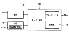
- the center server 1 includes a communication unit 11, a storage unit 12, and a center control unit 13.
- the communication unit 11 is a communication interface for communicating with the mobile terminals (for example, mobile phones) possessed by the drivers of the in-vehicle devices 3a to 3d and the vehicles 2a to 2d, the management communication terminal of the transportation company, and the like.
- the storage unit 12 stores a program executed by the center control unit and a vehicle information database 12a described later.
- the center control unit 13 executes a web service process 13a and a drowsiness handling process 13b described later by executing a program recorded in the storage unit 12.
- the center control unit 13 may be realized by a CPU such as a personal computer or a workstation, a RAM, a ROM, or the like.
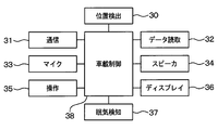
- each of the on-vehicle devices 3a to 3d has a position detection unit 30, a communication unit 31, a data reading unit 32, a microphone 33, a speaker 34, an operation unit 35, and a display. 36, a drowsiness detection unit 37, and an in-vehicle control unit 38.
- the position detection unit 30 is a sensor for detecting the current position of the vehicle on which the vehicle is mounted by satellite navigation and autonomous navigation, such as a GPS receiver, an acceleration sensor, and a yaw rate sensor.
- the communication unit 31 is a wireless communication interface for enabling communication with the center server 1.
- the data reading unit 32 is a device that reads a portable storage medium (for example, an SD card) in which information of a driver of a vehicle on which the device is mounted is recorded.
- the microphone 33 is configured and arranged so that the voice of a driver sitting in the driver's seat of the vehicle on which the vehicle is installed can be input.
- the speaker 34 has a configuration and an arrangement capable of outputting sound so that it can be heard by a driver sitting in the driver's seat of the vehicle on which the vehicle is mounted.
- the operation unit 35 has a configuration and an arrangement that can be directly operated by a driver sitting in the driver's seat of the vehicle on which the vehicle is mounted.
- the display 36 is a device that displays visual information (characters, images, etc.) to a driver sitting in the driver's seat of the vehicle on which the vehicle is mounted, and can be realized by an LCD, for example.
- the drowsiness detection unit 37 is a sensor for detecting the drowsiness level of the driver sitting in the driver's seat of the vehicle on which the vehicle is mounted.
- the drowsiness detection unit 37 may be a camera that repeatedly captures a driver's face image and inputs it to the in-vehicle control unit 38.
- the drowsiness detection unit 37 may be a combination of a device that emits a perceptual signal such as light or sound to the driver and a confirmation button that is operated by the driver in response to the perceptual signal.
- the in-vehicle control unit 38 calculates the drowsiness level of the driver by a known method based on the driver's face image sequentially input from the camera. In the latter case, the in-vehicle control unit 38 calculates the sleepiness level of the driver according to the delay time based on the input of the delay time of the confirmation button operation with respect to the perceptual signal.
- the in-vehicle control unit 38 is realized by a microcomputer having a CPU, RAM, ROM, flash memory, and the like. Various processes, which will be described later, of the in-vehicle control unit 38 are realized by the CPU executing the program recorded in the ROM.
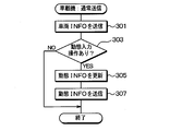
- the vehicle-mounted control unit 38 of each of the vehicle-mounted devices 3a to 3d performs the normal transmission process shown in FIG. 4 repeatedly (for example, periodically at intervals of 1 minute) while the vehicle main power supply (for example, IG) is on. It has become.
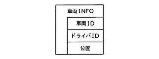
- the in-vehicle control unit 38 first reads vehicle information from the flash memory in step 301, and transmits the vehicle information to the center server 1 using the communication unit 31.
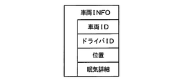
- the structure of the vehicle information transmitted at this time is as shown in FIG. That is, the vehicle information includes a vehicle ID of the mounting destination vehicle, a driver ID of a driver who uses the mounting destination vehicle, and position information of the mounting destination vehicle.
- the vehicle ID is an identification code for distinguishing the vehicle on which the in-vehicle control unit 38 is mounted from other vehicles, and is recorded in advance in a flash memory or the like of the in-vehicle control unit 38. Since the vehicle and the in-vehicle device mounted on the vehicle are in a fixed one-to-one relationship, the vehicle ID is an identification code for distinguishing the in-vehicle device from other in-vehicle devices (that is, in-vehicle). Machine ID).
- the driver ID is an identification code for distinguishing the driver of the vehicle on which the in-vehicle control unit 38 is mounted from other drivers.
- a portable storage medium for example, an SD card
- the data reading unit 32 reads the driver ID
- the in-vehicle control unit 38 stores the read driver ID in the flash memory.
- the position information is information indicating the current position of the vehicle on which the in-vehicle control unit 38 is mounted, and the in-vehicle control unit 38 sequentially acquires from the position detection unit 30.
- step 303 it is determined whether or not the driver has performed a dynamic input operation on the operation unit 35.
- the dynamic input operation is an input operation that changes the dynamics of the vehicle.
- the operation unit 35 has a plurality of buttons that accept dynamic input operations. Specifically, operation start button, operation end button, break start button, break end button, rest start button, rest end button, loading start button, loading end button, unloading start button, unloading end button, actual vehicle Button, empty button.
- step 303 If any one of these buttons for dynamic input operation is newly pressed, it is determined in step 303 that dynamic input is present, and the process proceeds to step 305. If these dynamic input operation buttons are not newly pressed, it is determined in step 303 that there is no dynamic input, and the processing of FIG.
- step 305 the dynamic information stored in the flash memory is updated based on the contents of the dynamic input operation, that is, based on the type of the pressed button for the dynamic input operation.
- the structure of the dynamic information is as shown in FIG. That is, the dynamic information includes an operation end time, an operation start time, break / rest information, loading / unloading information, and actual / empty vehicle information.
- Rest / rest information is also called break or rest information.
- the loading / unloading information is also called loading / unloading information.
- Actual vehicle / empty vehicle information is also referred to as actual vehicle or empty vehicle information.
- operation means that the vehicle is used for business (for example, delivery of luggage).
- the term “rest” means that the driver temporarily takes a rest for a relatively short time during the operation of the vehicle. A break of less than one hour, such as a toilet break, corresponds to a break.
- the term “rest” means that the driver temporarily stops working for a relatively long time during the operation of the vehicle. A rest of one hour or more for a nap corresponds to a rest.
- loading and unloading refer to the act of a driver loading and unloading a vehicle during operation of the vehicle, respectively.
- the actual vehicle means a state where no load is mounted on the vehicle, and the empty vehicle means a state where no load is mounted on the vehicle. It should be noted that the vehicle continues to be in operation even during breaks, rests, loading and unloading.
- the in-vehicle control unit 38 updates the dynamic information as follows. When the operation of the mounted vehicle ends and the operation end button is pressed, the value of the operation end time is rewritten to the current time (including date information). In addition, when the operation start button is pressed at the start of operation of the installed vehicle, the value of the operation start time is rewritten to the current time (including date information), and the values of rest / rest information and loading / unloading information Change to “None”.
- the break start button when the driver starts taking a break, the value of the break / rest information is changed to “during break”.
- the break end button is pressed after the driver has finished the break, the value of the break / rest information is changed to “none”.
- the rest start button is pressed when the driver starts taking rest, the value of rest / rest information is changed to “resting”. Also, when the rest end button is pressed after the driver has finished resting, the value of the rest / rest information is changed to “none”.
- the loading start button is pressed when the driver starts loading, the value of loading / unloading information is changed to “loading”. If the loading end button is pressed after the driver finishes loading, the value of loading / unloading information is changed to “none”.
- the unloading start button is pressed when the driver starts unloading
- the value of loading / unloading information is changed to “Unloading”.
- the unloading end button is pressed after the driver has finished unloading, the value of the loading / unloading information is changed to “none”.
- the in-vehicle control unit 38 changes the value of the actual vehicle / empty vehicle information to “actual vehicle”. Further, when the vehicle has changed from being loaded to not being loaded, the driver presses the empty vehicle button, and in that case, the in-vehicle control unit 38 changes the value of the actual vehicle / empty vehicle information to “empty vehicle”.
- step 307 following step 305 the in-vehicle control unit 38 transmits the updated dynamic information and the vehicle ID of the mounting destination vehicle to the center server 1 using the communication unit 31, and thereafter ends the processing of FIG. To do.
- each of the vehicle-mounted devices 3a to 3d repeatedly transmits vehicle information to the center server 1 and transmits a vehicle ID and dynamic information whenever the dynamic information changes.
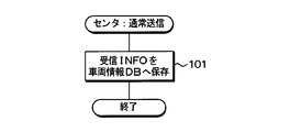
- the center server 1 every time the center control unit 13 receives vehicle information or dynamic information from the in-vehicle devices 3a to 3d via the communication unit 11, the normal reception process of FIG.
- the received information (vehicle information or dynamic information) is stored in the vehicle information database 12a, and then the normal reception process is terminated.
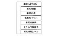
- the vehicle information database 12a is configured as shown in FIG. That is, it includes vehicle-specific movement information, vehicle-specific position information, vehicle-specific driver information, vehicle-specific contact information, and driver-specific contact information.
- the vehicle-specific movement information includes the movement information for each vehicle and is updated by the processing in step 101. Specifically, when the center control unit 13 receives the dynamic information together with the vehicle ID from any one of the in-vehicle devices 3a to 3d, in step 101, the center control unit 13 associates the received dynamic information with the vehicle ID to associate the vehicle ID with the vehicle ID. Record in separate dynamic information. At that time, the dynamic information already recorded in association with the same vehicle ID in the dynamic information for each vehicle is deleted. Therefore, the latest movement information is stored for each vehicle ID in the movement information for each vehicle.
- the vehicle location information includes a history of the location of each vehicle, and is updated by the processing in step 101. Specifically, when the center control unit 13 receives vehicle information from any one of the in-vehicle devices 3a to 3d, in step 101, the center control unit 13 associates the vehicle ID and the position information included in the received vehicle information. And additionally record in the vehicle-specific position information. By doing in this way, the history of the past location and the current location is recorded for each vehicle ID in the vehicle location information.
- the vehicle-specific driver information is information indicating which driver is used for each vehicle, the vehicle ID and the driver ID are recorded in association with each other, and updated by the processing in step 101. Specifically, when the center control unit 13 receives vehicle information from any one of the in-vehicle devices 3a to 3d, in step 101, the center control unit 13 associates the vehicle ID and the driver ID included in the received vehicle information. Record in the vehicle-specific driver information.
- the old association information is deleted so that no contradiction occurs in the association in the vehicle-specific driver information. Specifically, when the vehicle ID included in the received vehicle information is associated with another driver ID in the vehicle-specific driver information, the association information with the other driver ID is deleted. Similarly, when the driver ID included in the received vehicle information is associated with another vehicle ID in the vehicle-specific driver information, the association information with the other vehicle ID is deleted.
- the telephone number of the in-vehicle device mounted on the vehicle is recorded for each vehicle.
- the contact information for each vehicle is recorded in advance in the vehicle information database 12a of the storage unit 12 by the administrator of the center server 1 by a known method.
- the contact information for each driver records the phone number and e-mail address (for example, e-mail address) of the portable terminal that the driver has for each driver, and also includes the name for each driver.
- the contact information for each driver is recorded in advance in the vehicle information database 12a of the storage unit 12 by the administrator of the center server 1 by a known method.
- the center control unit 13 executes a web service process 13a.
- the processing contents of the Web service processing 13a are as follows.
- the center control unit 13 receives a browsing request for the vehicle information database 12a from another communication terminal having a Web browser function (for example, a management computer owned by the same transportation company)
- the center control unit 13 communicates the contents of the vehicle information database 12a with the communication. Send to the terminal.
- the vehicle information database 12a can be browsed by another communication terminal.
- the vehicle status notification system also functions as an operation management system.
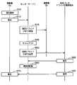
- FIG. 9 shows an operation sequence of the entire status notification system in the first case where drowsiness is detected.
- the in-vehicle control unit 38 of each of the in-vehicle devices 3a to 3d calculates the drowsiness level of the driver of the vehicle 2a based on the signal input from the drowsiness detection unit 37 repeatedly (for example, periodically at a cycle of 1 second).
- the value of sleepiness level is calculated from 0 to 100, for example, in increments of 1; 0 when the user is completely awake, 100 when the child is completely asleep, and the value becomes closer to a fully sleeping state. growing.
- the in-vehicle controller 38 determines that the occurrence of sleepiness has been detected only when the sleepiness level exceeds a predetermined sleepiness threshold (for example, 50).
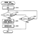
- step 500 of FIG. 9 the in-vehicle control unit 38 of the in-vehicle device 3a determines that the occurrence of drowsiness has been detected.
- the vehicle-mounted control unit 38 of the vehicle-mounted device 3a performs sleepiness generation notification in step 510 based on the determination that the generation of sleepiness has been detected.
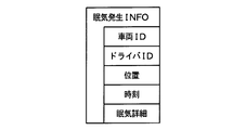
- the sleepiness occurrence information shown in FIG. 10 is transmitted to the center server 1 using the communication unit 31.
- the drowsiness occurrence information includes the vehicle ID of the mounting destination vehicle, the driver ID of the driver using the mounting destination vehicle, the position information of the mounting destination vehicle, time information, and detailed sleepiness information.
- the time information is current time information.
- the sleepiness detailed information includes the sleepiness level used when it is determined that the occurrence of sleepiness is detected.
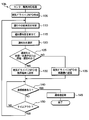
- the center control unit 13 of the center server 1 When the center control unit 13 of the center server 1 receives this drowsiness occurrence information via the communication unit 11, the center control unit 13 executes the drowsiness handling process 13b. In the sleepiness handling process, the center control unit 13 first creates sleepiness driver information in step 105 as shown in FIG.
- the center control unit 13 first reads the vehicle ID and driver ID from the received drowsiness occurrence information. And the contact telephone number of the vehicle equipment 3a corresponding to the said vehicle ID is read from the contact information classified by vehicle in the vehicle information database 12a, and is included in sleepiness driver information. Further, the driver name corresponding to the driver ID is read from the contact information for each driver in the vehicle information database 12a and included in the drowsiness driver information.
- the drowsiness driver information also includes information indicating that the driver's drowsiness has been detected.
- the center control unit 13 specifies another vehicle in operation based on the vehicle-specific movement information in the vehicle information database 12a.
- a vehicle equipped with an in-vehicle device that has become a transmission destination of drowsiness driver information to be described later after starting the processing of FIG. 11 is excluded from the target to be specified.
- the specific identification method is as follows.
- the in-vehicle control unit 38 first identifies the movement information to be extracted from the movement information (see FIG. 6) included in the movement information for each vehicle. Specifically, the dynamic information corresponding to the vehicle ID included in the received sleepiness occurrence information is excluded from the extraction target. Moreover, the dynamic information corresponding to the vehicle ID of the vehicle-mounted device that has become the transmission destination of drowsiness driver information described later after the processing of FIG. 11 is started is also excluded from the extraction target. All the dynamic information remaining as a result is taken as an extraction target.
- operation presence / absence information that indicates whether or not the vehicle is operating is extracted from each piece of dynamic information to be extracted.
- the operation presence / absence information to be extracted is a set of an operation end time and an operation start time. If the operation end time is later in time than the operation start time, it is determined that the vehicle with the vehicle ID corresponding to the dynamic information is not in operation. On the other hand, when the operation end time is earlier in time than the operation start time, it is determined that the vehicle with the vehicle ID corresponding to the dynamic information is in operation. When the operation end time is a default value or an empty value and the operation start time is neither a default value nor an empty value, it is determined that the vehicle with the vehicle ID corresponding to the dynamic information is in operation.
- the operation start time is a default value or an empty value, it is determined that the vehicle with the vehicle ID corresponding to the dynamic information is not in operation.
- the vehicle 2d is not in operation among the vehicles 2b, 2c, and 2d, and that the vehicles 2b and 2c are in operation.
- the notification priority of the operating vehicles 2b and 2c specified in step 110 is assigned.
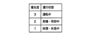
- the notification priority is set based on the operation state of each vehicle. The correspondence between the operation state and the notification priority is as shown in FIG. In other words, the highest priority is 3 for the operation status “Driving”, the next highest notification priority 2 is “Loading / Unloading”, and the operation status is “Resting / Resting”. Is the lowest notification priority.
- the reason why the notification priority of “Driving” is highest is that the possibility of notifying the notification of sleepy driver information is the highest. “Loading / unloading” is assigned a higher notification priority than “resting / resting”. Drivers who are loading / unloading are assigned a higher priority than those who are resting. This is because there is a high possibility that the user will notice the sleepiness driver information.
- the operation state of each vehicle 2b, 2c is specified based on the dynamic information corresponding to the vehicle ID of the vehicle 2b, 2c in the vehicle information database 12a. Specifically, the operation state is specified based on the operation state information in each dynamic information (see FIG. 6), that is, rest / rest information and loading / unloading information.
- both the break / rest information and the loading / unloading information have a value of “None”, that is, if the driver is not taking a rest and is not loading or unloading, the service is performed. It is determined that the state is “Driving”. If the loading / unloading information is “loading” or “unloading”, it is determined that the operation state is “loading / unloading”. If the rest / rest information is “resting” or “resting”, it is determined that the operation state is “resting / resting”. In the example of FIG. 9, the notification priority of the vehicle 2b during driving is set to 3. In addition, the notification priority of the vehicle 2c in which the driver is resting is set to 1 (resting or resting).
- step 120 based on the notification priority set in step 115, one vehicle assigned the highest notification priority is selected as the notification destination vehicle.
- the vehicle 2b having the highest notification priority is selected as the notification destination vehicle.
- the reason for selecting only one vehicle at a time as a notification destination vehicle is that even if multiple units are selected, the in-vehicle device 3a of the sleepy vehicle 2a and the telephone line are connected to one, so that the call was made even though the call was made. This is to prevent things from happening.
- step 125 it is determined whether the operation state of the notification destination vehicle 2b is “resting / resting” or “loading / unloading”.
- the operation state of the notification destination vehicle 2 b is “driving”, it is determined that it is neither “resting / resting” nor “loading / unloading”, and the process proceeds to step 135.
- step 135 the drowsiness driver information created in step 105 is transmitted to the notification destination vehicle selected in step 120 using the notification unit 11 (step 515 in FIG. 9).
- this drowsiness driver information includes the name of the driver of the vehicle 2a in which drowsiness is detected, the telephone number of the in-vehicle device 3a, and information indicating that the drowsiness of the driver is detected.
- step 140 it is determined in step 140 whether or not a contact report has been received from the transmission destination of drowsiness driver information. If it is determined that it has not been received, the process proceeds to step 150, where it is determined whether a predetermined time-out period (for example, 3 minutes) has elapsed since the transmission of the last sleepy driver information. If not, the process returns to step 140. . That is, it waits for a contact report from the transmission destination of sleepy driver information for the timeout time.
- a predetermined time-out period for example, 3 minutes
- step 310 the display 36 is caused to display based on the received drowsiness driver information.
- FIG. 14 shows an example of the display.
- the name of the driver included in the drowsiness driver information is displayed.
- the contact telephone number such as the telephone number of the in-vehicle device 3a
- the fact that the drowsiness of the driver has been detected are displayed.
- a “TEL” button and a “Close” button are displayed. Since the driver of the vehicle 2b is operating and driving, in most cases, the driver immediately notices the display of step 310.
- step 315 it is determined whether or not an operation for selecting the “TEL” button has been performed on the operation unit 35, and if not, the process proceeds to step 320.
- Step 320 it is determined whether or not an operation for selecting the “Close” button has been performed on the operation unit 35. If not, the process returns to Step 315. That is, it waits until the “TEL” button or the “Close” button is selected.
- the driver of the vehicle 2b selects the “TEL” button when calling the driver of the vehicle 2a. If the driver of the vehicle 2a decides not to call the driver of the vehicle 2a for any reason, the driver of the “close” button Perform a selection operation.
- the driver of the vehicle 2b decides to make a phone call, and uses the operation unit 35 to select the “TEL” button. Then, the in-vehicle control unit 38 determines in step 320 that the “TEL” button selection operation has been performed, and proceeds to step 325.
- step 325 the communication unit 31 is used to make a telephone call to the contact telephone number (such as the telephone number of the in-vehicle device 3a) of the drowsiness-generating vehicle 2a included in the drowsiness driver information (step 525 in FIG. 9).
- the contact telephone number such as the telephone number of the in-vehicle device 3a
- an incoming call from the in-vehicle device 3b occurs in the in-vehicle device 3a of the sleepiness-generating vehicle 2a (step 530 in FIG. 9).
- the vehicle-mounted control unit 38 of the vehicle-mounted device 3a detects that a telephone call has been received via the communication unit 31, it performs an off-hook process to connect the telephone line with the telephone caller.
- the voice of the driver of the vehicle 2b is transmitted as a voice signal by the microphone 33 of the in-vehicle device 3b and transmitted through the telephone line, and is output as a sound by the speaker 34 of the in-vehicle device 3a.
- the voice of the driver of the vehicle 2a is converted into a voice signal by the microphone 33 of the in-vehicle device 3a and transmitted through the telephone line, and is output as a sound by the speaker 34 of the in-vehicle device 3b. Therefore, the driver of the drowsiness generating vehicle 2a and the driver of the vehicle 2b can talk.
- the driver of the vehicle 2b may instruct the driver of the drowsiness-generating vehicle 2a to stop the vehicle 2a and take a break. Or you may encourage the conversation for awakening the driver of the drowsiness generation vehicle 2a.
- the latter performs the conversation between the two, it contributes well to the awakening of the driver of the drowsiness generating vehicle 2a. This is because the conversation between people has a stronger effect of activating the brain than a simple physical stimulation.
- step 330 the communication unit 31 is used to transmit a communication report including the driver ID of the driver of the installation destination vehicle 2b to the center server 1 (step 535 in FIG. 9), and the processing in FIG. To do.
- the communication part 31 becomes a structure which can be compatible with the transmission to the center server 1 and the telephone line connection with the other vehicle equipment 3a simultaneously.
- step 140 when the center control unit 13 receives this communication report via the communication unit 11 in the repetition of steps 140 and 150, the center control unit 13 determines in step 140 that there is a communication report and proceeds to step 145.
- step 145 the driver ID included in the received communication report is recorded in the storage unit 12 as the driver ID of the contact (step 540 in FIG. 9), and the drowsiness handling process 13b in FIG. 11 is terminated.
- the driver ID of the contact person is accumulated in the storage unit 12 every time the driver of one of the vehicles makes a telephone contact with the drowsy vehicle.
- the history of driver IDs accumulated in this way can be reflected later in work evaluation at a transportation company.
- FIG. 15 shows an operation sequence of the entire status notification system in the second case where sleepiness is detected.
- the center server 1 transmits sleepiness driver information to the in-vehicle device 3b having the highest notification priority (step 500).
- the operation of 515) is exactly the same as in the first case.
- This example is different from the first example in that after the vehicle-mounted control unit 38 of the vehicle-mounted device 3b causes the display 36 to display the display shown in FIG. 14 on the display 36, the driver of the vehicle 2b calls the phone for some rare reason. It is to decide not to apply. Following this determination, the driver of the vehicle 2b uses the operation unit 35 to select the “Close” button. Then, the in-vehicle control unit 38 determines that the operation of selecting the “Close” button has been performed in Step 320, bypasses Steps 325 and 330, and ends the process of FIG. 13.
- the center control unit 13 since the contact report is not transmitted from the in-vehicle device 3b to the center server 1, the center control unit 13 times out while repeating the execution of steps 140 and 150 after transmitting the drowsiness driver information last time. Time passes (step 545 in FIG. 15). At that time, the center control unit 13 determines in step 150 that the timeout time has elapsed, and returns to step 110.
- step 110 another vehicle in operation is identified again by the method already described.
- the vehicle 2c since the drowsiness driver information has already been transmitted to the vehicle 2b, only the vehicle 2c is specified as the other vehicle in operation.
- the driver of the vehicle 2c is still resting, and the dynamic information corresponding to the vehicle ID of the vehicle 2c does not change in the dynamic information for each vehicle.
- the vehicle 2d may start operation after the previous step 110 is executed and before the current step 110 is executed. In that case, since the dynamic information of the vehicle 2d changes in the vehicle information database 12a by the operation of the normal operation described above, the vehicle 2d is also specified as the other vehicle in operation.
- step 115 following step 110 the notification priority of the vehicle 2 c in operation is assigned, but the operation state of the vehicle 2 c based on the vehicle-specific movement information is still “break. Since it is “resting”, the notification priority is set to 1 (resting).
- step 120 the vehicle to which the highest notification priority is assigned is selected as the notification destination vehicle.
- the notification priority is assigned only to the vehicle 2c. , Selected as a notification destination vehicle.
- step 125 it is determined that the operation state of the notification destination vehicle 2 c is “resting / resting”, and the process proceeds to step 130.
- step 130 the drowsiness driver information created in step 105 is transmitted to the portable terminal possessed by the driver of the notified vehicle 2c selected in step 120.
- the contact information of the portable terminal possessed by the driver of the notification destination vehicle 2c is specified as follows.
- the driver ID corresponding to the vehicle ID of the notification destination vehicle 2c is read from the vehicle-specific driver information in the vehicle information database 12a. Then, the telephone number and the e-mail address corresponding to the driver ID are extracted from the contact information for each driver in the vehicle information database 12a, and the driver of the notification destination vehicle 2c has one of these extracted items. It will be the contact information of the mobile terminal. For example, when both the phone number and the e-mail address are successfully extracted, the e-mail address is given priority as the contact, and only when the phone number is successfully extracted, the phone number may be used as the contact.
- the drowsiness driver information may be transmitted as text data. Then, even if the driver of the vehicle 2c is resting or resting outside the vehicle 2c, he / she operates his portable terminal to read the incoming e-mail, reads the name of the sleepy driver and the in-vehicle state of the sleepy vehicle 2a
- the contact telephone number of the machine 3a can be known.
- a telephone line with the telephone number as a partner is connected, a voice signal that reads out drowsiness driver information is created, and the voice signal may be transmitted through the telephone line. Then, even if the driver of the vehicle 2c is resting or resting outside the vehicle 2c, the driver of the vehicle 2c goes off-hook with respect to the incoming call to the portable terminal, and the name of the sleepy driver and the sleepy vehicle 2a are transmitted through the telephone line. The contact telephone number of the in-vehicle device 3a can be heard.
- the driver of the vehicle 2c who knows this drowsiness driver information decides to call the contact telephone number of the in-vehicle device 3a in the drowsiness driver information. And it acts to inform the center server 1 that it has decided to call.
- a reply e-mail is transmitted as a reply to this e-mail (step 555 in FIG. 15).
- This reply e-mail corresponds to a contact report. Note that, unlike the case of FIG. 15, if the driver of the vehicle 2c decides not to call for some rare reason, a reply e-mail is not transmitted. That is, no contact report is sent.
- the portable terminal when the sleepy driver information is heard through the telephone line, it is notified that the telephone number of the in-vehicle device 3a is called through this telephone line. Specifically, by speaking a predetermined word (for example, “call”), the portable terminal is caused to transmit a voice signal of the word to the center server 1 (step 555 in FIG. 15). In this case, the voice signal of the predetermined word corresponds to the communication report. Alternatively, by pressing a predetermined numeric button on the portable terminal, the portable terminal is caused to transmit a tone signal corresponding to the numeric button to the center server 1 (step 555 in FIG. 15). In this case, the tone signal corresponds to the communication report. Note that, unlike the case of FIG. 15, if the driver of the vehicle 2c decides not to call for some rare reason, the telephone line is not issued without issuing the predetermined word or pressing the number button. Disconnect. That is, no contact report is sent.
- a predetermined word for example, “call”
- the portable terminal is caused to transmit a
- the center control unit 13 receives the contact report via the communication unit 11 in the repetition of steps 140 and 150.
- step 140 it is determined that there is a communication report, and the process proceeds to step 145.
- step 145 the driver ID of the driver that transmitted the sleepiness driver information in the immediately preceding step 130 is recorded in the storage unit 12 as the driver ID of the contact (step 560 in FIG. 15).
- the process 13b is terminated.
- the driver of the vehicle 2c makes a call to the contact telephone number of the in-vehicle device 3a in the sleepiness driver information using the portable terminal that has received the sleepiness driver information (step 565 in FIG. 15).
- an incoming call from the portable terminal is generated in the in-vehicle device 3a of the sleepiness-generating vehicle 2a (step 570 in FIG. 15).
- the subsequent conversation between the driver of the vehicle 2a and the driver of the vehicle 2c and the effect thereof by the telephone line between the in-vehicle device 3b and the portable terminal are the same as those after step 530 in the first case of FIG.
- the center server 1 when the center server 1 receives the drowsiness occurrence information from the in-vehicle device 3a, one of the operating vehicles 2a and 2b is set as a notification destination vehicle.
- the drowsiness driver information is notified to the driver of the notification destination vehicle. Since the drivers of the vehicles 2b and 2c that are in operation are performing business, there is a high possibility that they can respond to the notification of the predetermined situation. Therefore, compared with the case where only the operation manager is relied upon, it becomes possible to cope with the situation of the occurrence of sleepiness with a higher probability.
- drowsiness driver information is notified to a plurality of drivers one after another in order of priority until a driver that makes a call to the vehicle-mounted device 3a of the drowsiness generating vehicle 2a is found. It becomes possible to deal with the situation of sleepiness.
- the drowsiness driver information is notified to the drivers of the vehicles 2b and 2c belonging to the same transportation company as the drowsiness generating vehicle 2a, there is an effect that the morale and cohesion between the employees of the transportation company is increased.
- the first difference is the content of the vehicle information transmitted by the in-vehicle control unit 38 of the in-vehicle devices 3a to 3d in step 301 of FIG.
- the second difference is the information recorded by the center control unit 13 in step 101 of FIG. 7 and the configuration of the recording destination vehicle information database 12a.
- the third difference is the content of notification priority assignment performed by the center control unit 13 of the center server 1 in step 115 of FIG. About other than these, it is the same as 1st Embodiment.
- the three differences will be described.
- the vehicle-mounted control unit 38 of the vehicle-mounted devices 3a to 3d of this embodiment transmits vehicle information having the configuration shown in FIG. That is, the vehicle information includes the vehicle ID of the mounting destination vehicle, the driver ID of the driver using the mounting destination vehicle, and the position information of the mounting destination vehicle, which is the same as in the first embodiment. In the form, detailed sleepiness information is also included. This drowsiness detailed information is the same as the drowsiness detailed information included in the drowsiness occurrence information transmitted in step 510 of FIGS.
- the in-vehicle control unit 38 of the in-vehicle devices 3a to 3d calculates the drowsiness level of the driver of the vehicle 2a in the same manner as described in the first embodiment in step 301 of FIG.
- the calculated sleepiness level is calculated whether the calculated sleepiness level exceeds the predetermined sleepiness threshold (for example, 50) shown in the first embodiment, is the same as the predetermined threshold, or falls below the threshold.
- Detailed sleepiness information including the level is transmitted to the center server 1.
- the center server 1 when the center control unit 13 receives the vehicle information including the sleepiness detailed information via the communication unit 11, the vehicle information is stored in the vehicle information database 12a in step 101 of FIG. Thereafter, the normal reception process is terminated.
- the driver ID in the vehicle information and the storage method of the location information of the mounted vehicle are the same as in the first embodiment.
- vehicle-specific sleepiness level information is newly provided in the vehicle information database 12a. Keep it.
- the sleepiness level included in the received sleepiness detailed information is recorded in the vehicle-specific sleepiness level information in association with the vehicle ID included in the received vehicle information.
- the drowsiness level already recorded in association with the same vehicle ID in the vehicle-specific sleepiness level information is deleted. Accordingly, in the vehicle-specific sleepiness level information, the latest sleepiness level of the driver of the vehicle corresponding to the vehicle ID is updated for each vehicle ID every time vehicle information is received.
- step 115 of FIG. 11 the center control unit 13 assigns the notification priority of the operating vehicles 2b and 2c specified in step 110 based on the operation state of each vehicle in the first embodiment. Is the same.
- the correspondence relationship between the operation state and the notification priority in the present embodiment is as shown in FIG. Specifically, with respect to the correspondence relationship of the first embodiment (see FIG. 12), the operation state is changed to be further divided into two cases according to the value of sleepiness level when the driving state is “driving”. ing.
- the notification priority is given to the vehicle having the highest drowsiness level among the vehicles whose operation state is “driving” and whose operation state is “driving”. 4 is the highest. And for the vehicles whose driving state is “Driving” and whose driving state is “Driving” and whose sleepiness level is not maximum, the notification priority is the second. High 3 is assumed. Similarly to the first embodiment, the notification priority when the operation state is “loading / unloading” is the next highest 2, and the notification priority when the operation state is “resting / resting” is the lowest 1.
- the sleepiness levels of the drivers of the vehicles 2a and 2b are: Assume that they are 5 and 45, respectively, which are smaller than a predetermined sleepiness level threshold.
- the notification priority of the vehicle 2b is 4, and the notification priority of the vehicle 2a is 3.
- the sleepiness driver information is transmitted from the center server 1 to the in-vehicle device 3b of the vehicle 2b (step 515 in FIG. 9). Then, as in the first case, when a telephone call is made from the in-vehicle device 3b to the in-vehicle device 3a (step 525), the telephone line between the in-vehicle device 3b and the in-vehicle device 3a is connected (step 530 in FIG. 9).
- the conversation between the driver of the vehicle 2a in which drowsiness is detected and the driver of the vehicle 2b in which the drowsiness level is relatively high is realized through this telephone line even if drowsiness is not detected. Therefore, the effect of the sleepiness awakening extends not only to the driver of the vehicle 2a in which sleepiness is detected, but also to the driver of the vehicle 2b on the call origination side. In this way, among the drivers of the vehicle in operation, by assigning a higher notification priority to a driver having a high drowsiness level, the efficiency of sleep awakening is increased.
- the operation of the vehicle status notification system of this embodiment will be described.
- the operation during normal operation is the same as in the first and second embodiments.
- the in-vehicle device 3a detects the occurrence of drowsiness in the vehicle 2a, it is as follows, unlike the first and second embodiments.
- step 600 of FIG. 19 the in-vehicle control unit 38 of the in-vehicle device 3a determines that the occurrence of drowsiness has been detected. Send to.
- the center control unit 13 of the center server 1 receives the drowsiness occurrence information via the communication unit 11, the center control unit 13 executes the drowsiness handling process 13b.
- the content of the drowsiness target process 13b is different from that of the first embodiment. .
- drowsiness driver information is created by the same method as step 105 in FIG.
- the other vehicle in operation is specified based on the vehicle-specific movement information in the vehicle information database 12a by the same method as step 110 in FIG.
- the vehicle-specific movement information in the vehicle information database 12a it is assumed that only the vehicles 2b and 2c are operating except for the vehicle 2a.
- step 615 the center control unit 13 transmits the drowsiness driver information to all the in-vehicle devices 3b and 3c of the specified other vehicles 2b and 2c in operation, unlike the first embodiment.
- step 620 processing of the group call service 700 is started.
- the group call service 700 is a service that allows users (drivers) of a plurality of in-vehicle devices to perform simultaneous conversations (can perform group calls) through a plurality of in-vehicle devices participating in the service.
- the feature is that a plurality of in-vehicle devices may be three or more.
- the main processing performed by the center control unit 13 in the group call service 700 is as follows. First, when a participation application including a vehicle ID is received from the in-vehicle device, the vehicle ID is registered in the client list in the RAM of the center control unit 13. Then, when a plurality of (or three or more) vehicle IDs are registered in the client list, it is assumed that voice data is received from the in-vehicle device corresponding to one vehicle ID in the client list. In that case, the received audio data is transmitted to the vehicle-mounted devices of all vehicle IDs (two or more) other than the one vehicle ID in the client list.
- the in-vehicle control unit 38 transmits a drowsiness generation notification in step 610, and then proceeds to step 625 to perform processing for participating in the group call service 700.
- the participation application including the vehicle ID of the mounting destination vehicle 2 a is transmitted to the center server 1 using the communication unit 31.
- the center control unit 13 registers the vehicle ID of the drowsiness-generating vehicle 2a in the client list.
- the in-vehicle control unit 38 causes the display 36 to display based on the received drowsiness driver information in the same processing as step 310 in FIG. Then, in the same process as steps 315 and 320, the process waits until the “TEL” button or the “Close” button is selected. If the close button is selected during standby, the process at the time of receiving drowsiness driver information is terminated as in FIG.
- the center control part 13 performs the process for participating in the group call service 700 unlike the first embodiment. Specifically, the participation application including the vehicle IDs of the mounting destination vehicles 2b and 2c is transmitted to the center server 1 using the communication unit 31 (steps 630 and 635). Thereby, the center control unit 13 registers the vehicle IDs of the vehicles 2b and 2c in the client list.
- the in-vehicle control unit of the in-vehicle device 3a repeatedly determines whether or not the drowsiness level of the driver of the drowsiness-generating vehicle 2a has fallen below the predetermined drowsiness threshold after transmitting the participation application.
- the drowsiness cancellation notification is sent to the center using the communication unit 31. It transmits to the server 1 (step 645).
- the group server 700 is forcibly terminated without waiting for a special termination operation to be performed on the operation unit 35 of the in-vehicle devices 3a, 3b, and 3c. (Step 650). Thereafter, group calls cannot be made. As described above, when the sleepiness of the driver is resolved, the group call service 700 is terminated, so that the group call is not continued gently even though the driver is not necessary.
- the in-vehicle control unit 38 of the in-vehicle devices 3a to 3d compares the drowsiness level with the drowsiness threshold, and transmits the drowsiness occurrence information to the center server 1 when the drowsiness level exceeds the drowsiness threshold. It is supposed to be. However, this need not be the case.
- the vehicle-mounted control unit 38 of the vehicle-mounted devices 3a to 3d repeatedly calculates the drowsiness level, and each time it is calculated, the drowsiness occurrence information including the drowsiness level in the drowsiness detailed information is compared without comparing with the drowsiness threshold. You may come to transmit. In that case, the center control unit 13 of the center server 1 compares the sleepiness level in the received sleepiness occurrence information with the sleepiness threshold. As a result of the comparison, only when the sleepiness level exceeds the sleepiness threshold, the sleepiness handling process shown in FIG. 11 is executed in the first and second embodiments, and step 615 and subsequent steps in FIG. 19 are executed in the third embodiment. .
- the in-vehicle control unit 38 does not compare the drowsiness level with the drowsiness threshold, but even if that is the case, calculating the first drowsiness level that exceeds the drowsiness threshold may cause drowsiness of the driver It corresponds to detecting.
- sleepiness occurrence information including the first sleepiness level exceeding the sleepiness threshold corresponds to sleepiness occurrence information indicating that the driver's sleepiness occurrence is detected.
- the center control part 13 when the center control part 13 receives sleepiness driver information, it transmits sleepiness driver information to the vehicle equipment of all the vehicles which are operating in the vehicle information database 12a. .
- the center control unit 13 may assign a notification priority to each operating vehicle as in step 115 of FIG.
- drowsiness driver information may be transmitted only to a driver of a vehicle that is in operation and whose notification priority is a predetermined reference value (for example, 2) or more.
- the vehicle-mounted control part 38 participates in the group call service 700 in the vehicle-mounted apparatuses 3b and 3c which participate in the group call service 700 except the vehicle-mounted apparatus 3a of the drowsiness generation vehicle 2a.
- the communication report may be transmitted to the center server 1.
- the contents of this communication report are the same as those in the first and second embodiments.
- the center server 1 that has received this contact report records the driver ID included in the received contact report in the storage unit 12 as the driver ID of the contact, as in the first and second embodiments.
- the in-vehicle device 3a detects the occurrence of sleepiness of the driver of the vehicle 2a
- the vehicle 2a is an example of a first vehicle
- the in-vehicle device 3a is an example of a first in-vehicle device.
- the vehicle 2b or 2c is an example of the first vehicle
- the in-vehicle device 3b or 3c is an example of the first in-vehicle device.
- the center control unit 13 of the center server 1 transmits the drowsiness driver information to the communication terminal that is the transmission source of the received browsing request in the Web service processing 13a. Also good.
- the in-vehicle device 3a notifies the center server 1 of drowsiness occurrence information based on the fact that the vehicle 2a detects a predetermined situation of “driver drowsiness occurrence”. Yes.
- This drowsiness occurrence information corresponds to an example of situation occurrence information indicating that the predetermined situation has been detected.
- the predetermined situation is not necessarily limited to the generation of drowsiness by the driver, and any condition may be used as long as it is predetermined as a situation occurring in the vehicle 2a.
- the predetermined situation may be an accident occurrence in the vehicle 2a or a failure occurrence in the vehicle 2a.
- the operation in which the sleepiness in the first to third embodiments is replaced with an accident or a failure is realized.
- a method for detecting an accident level or a failure level by replacing the sleepiness level is well known.
- the relationship between the operation state and the notification priority shown in FIG. 12 may be changed according to whether the vehicle is an actual vehicle or an empty vehicle. That is, when assigning the notification priority of the vehicles 2b and 2c in operation at step 115 in FIG. 1, the center control unit 13 determines the notification priority as shown in FIG. 12, and further corrects the notification priority. . Specifically, for each vehicle 2b, 2c, if the actual vehicle / empty vehicle information included in the dynamic information corresponding to the vehicle ID of the vehicle is “actual vehicle”, the notification priority is not changed, and if it is “empty vehicle”, the notification priority is changed. The degree is increased by a predetermined amount (for example, 3). By doing in this way, priority is given to the vehicle-mounted device mounted in the empty vehicle as the vehicle-mounted device that notifies the presence of the vehicle in which an accident or failure has occurred.
- a predetermined amount for example, 3
- the center control unit 13 may include the current position of the vehicle in which the accident or failure occurred in the transmitted accident driver information or failure driver information in steps 130 and 135.
- the other vehicle in the empty vehicle can express to the location of the vehicle in which the accident or failure has occurred, and the load of the vehicle in which the accident or failure has occurred can be loaded on the other vehicle.
- the actual vehicle / empty vehicle information in the dynamic information transmitted from the in-vehicle device 3a to the center server 1 is one of the operation state information.
- the present disclosure receives, from each of a plurality of in-vehicle devices mounted on a plurality of vehicles and a plurality of in-vehicle devices, operation presence / absence information that indicates whether or not the vehicle on which the in-vehicle device is installed is operating,
- a center server that stores in the vehicle information database the operation presence / absence information for each of the plurality of vehicles, and the first in-vehicle device among the plurality of in-vehicle devices is a first mounting destination of the first in-vehicle device.
- the center server Based on detecting the predetermined situation of the vehicle, the center server is notified of the situation occurrence information indicating that the predetermined situation has been detected, and the center server receives the situation occurrence information from the first in-vehicle device. Based on the operation presence / absence information stored in the vehicle information database, a vehicle status that notifies a predetermined status of the first vehicle to a driver of the notification destination vehicle, with a running vehicle among a plurality of vehicles as a notification destination vehicle Notification system A.
- the center server notifies the driver of the vehicle in operation of the predetermined situation. . Since the driver of the vehicle in operation is performing business, there is a high possibility that the driver of the predetermined situation can take some action. Therefore, it is possible to deal with the situation with higher probability than when relying only on the operation manager.
- each step is expressed as S100, for example. Further, each step can be divided into a plurality of sub-steps, while a plurality of steps can be combined into one step. Further, each step configured in this manner can be referred to as a device or a module.
Landscapes
- Physics & Mathematics (AREA)
- General Physics & Mathematics (AREA)
- Traffic Control Systems (AREA)
Applications Claiming Priority (2)
| Application Number | Priority Date | Filing Date | Title |
|---|---|---|---|
| JP2013-234758 | 2013-11-13 | ||
| JP2013234758A JP6156082B2 (ja) | 2013-11-13 | 2013-11-13 | 車両状況通知システム |
Publications (1)
| Publication Number | Publication Date |
|---|---|
| WO2015072104A1 true WO2015072104A1 (ja) | 2015-05-21 |
Family
ID=53057057
Family Applications (1)
| Application Number | Title | Priority Date | Filing Date |
|---|---|---|---|
| PCT/JP2014/005504 Ceased WO2015072104A1 (ja) | 2013-11-13 | 2014-10-30 | 車両状況通知システム |
Country Status (2)
| Country | Link |
|---|---|
| JP (1) | JP6156082B2 (cg-RX-API-DMAC7.html) |
| WO (1) | WO2015072104A1 (cg-RX-API-DMAC7.html) |
Cited By (2)
| Publication number | Priority date | Publication date | Assignee | Title |
|---|---|---|---|---|
| EP3951725A4 (en) * | 2019-03-27 | 2022-06-15 | JVCKenwood Corporation | RECORDING CONTROL DEVICE, RECORDING CONTROL METHOD AND PROGRAM |
| JP2023070279A (ja) * | 2021-11-09 | 2023-05-19 | ソフトバンク株式会社 | 情報処理装置、移動体管理システム |
Families Citing this family (7)
| Publication number | Priority date | Publication date | Assignee | Title |
|---|---|---|---|---|
| JP3359332B2 (ja) | 2001-05-10 | 2002-12-24 | 井上スダレ株式会社 | すだれ及びその製法 |
| JP6377034B2 (ja) * | 2015-10-21 | 2018-08-22 | 三菱電機ビルテクノサービス株式会社 | 車両用眠気防止装置および車両用眠気防止方法 |
| JP6701951B2 (ja) * | 2016-05-20 | 2020-05-27 | アイシン精機株式会社 | 運転支援装置 |
| JP2018147027A (ja) * | 2017-03-01 | 2018-09-20 | オムロン株式会社 | 覚醒支援装置、方法およびプログラム |
| JPWO2018235347A1 (ja) * | 2017-06-21 | 2020-04-30 | 住友電気工業株式会社 | 運行システム、車載機、産業用車輌、フォークリフト、コンピュータプログラム、データ構造及び運行方法 |
| CN109816156A (zh) * | 2019-01-04 | 2019-05-28 | 北京百度网讯科技有限公司 | 无人驾驶物流车自主运营方法、装置及存储介质 |
| JP7266423B2 (ja) * | 2019-02-27 | 2023-04-28 | トヨタホーム株式会社 | 居眠り防止システム |
Citations (4)
| Publication number | Priority date | Publication date | Assignee | Title |
|---|---|---|---|---|
| JPH11283187A (ja) * | 1998-03-27 | 1999-10-15 | Aisin Seiki Co Ltd | 配車管理システム |
| JP2000172992A (ja) * | 1998-12-09 | 2000-06-23 | Fujitsu Ltd | 車載型車両誘導装置及び通信サーバシステム並びに代替車両誘導システム |
| JP2003254770A (ja) * | 2002-03-01 | 2003-09-10 | Sony Corp | 車両用ナビゲーション装置 |
| JP2006164147A (ja) * | 2004-12-10 | 2006-06-22 | Nissan Motor Co Ltd | 運転者の注意喚起システムおよびその処理方法並びに運転者の注意喚起システムを備えた通信システム |
Family Cites Families (1)
| Publication number | Priority date | Publication date | Assignee | Title |
|---|---|---|---|---|
| JP2003123198A (ja) * | 2001-10-15 | 2003-04-25 | Daiichi Fashion Service:Kk | 居眠り事故防止方法及びそのシステム |
-
2013
- 2013-11-13 JP JP2013234758A patent/JP6156082B2/ja not_active Expired - Fee Related
-
2014
- 2014-10-30 WO PCT/JP2014/005504 patent/WO2015072104A1/ja not_active Ceased
Patent Citations (4)
| Publication number | Priority date | Publication date | Assignee | Title |
|---|---|---|---|---|
| JPH11283187A (ja) * | 1998-03-27 | 1999-10-15 | Aisin Seiki Co Ltd | 配車管理システム |
| JP2000172992A (ja) * | 1998-12-09 | 2000-06-23 | Fujitsu Ltd | 車載型車両誘導装置及び通信サーバシステム並びに代替車両誘導システム |
| JP2003254770A (ja) * | 2002-03-01 | 2003-09-10 | Sony Corp | 車両用ナビゲーション装置 |
| JP2006164147A (ja) * | 2004-12-10 | 2006-06-22 | Nissan Motor Co Ltd | 運転者の注意喚起システムおよびその処理方法並びに運転者の注意喚起システムを備えた通信システム |
Cited By (3)
| Publication number | Priority date | Publication date | Assignee | Title |
|---|---|---|---|---|
| EP3951725A4 (en) * | 2019-03-27 | 2022-06-15 | JVCKenwood Corporation | RECORDING CONTROL DEVICE, RECORDING CONTROL METHOD AND PROGRAM |
| JP2023070279A (ja) * | 2021-11-09 | 2023-05-19 | ソフトバンク株式会社 | 情報処理装置、移動体管理システム |
| JP7431788B2 (ja) | 2021-11-09 | 2024-02-15 | ソフトバンク株式会社 | 情報処理装置、移動体管理システム |
Also Published As
| Publication number | Publication date |
|---|---|
| JP6156082B2 (ja) | 2017-07-05 |
| JP2015095141A (ja) | 2015-05-18 |
Similar Documents
| Publication | Publication Date | Title |
|---|---|---|
| JP6156082B2 (ja) | 車両状況通知システム | |
| US8761673B2 (en) | Short-range wireless communication apparatus | |
| CN107613144B (zh) | 自动呼叫方法、装置、存储介质及移动终端 | |
| CN104363569B (zh) | 一种基于情景感知的向移动用户推荐最优联系方式的方法 | |
| CN107040866A (zh) | 用于使用个人通信装置发起紧急呼叫的设备和方法 | |
| KR20110050275A (ko) | 차량 관련 이동통신 단말기의 운용 방법 및 시스템 | |
| JP2023029454A (ja) | 移動体装置、端末装置、情報処理システム及び情報処理方法並びに移動体装置用プログラム及び端末装置用プログラム | |
| US10410181B2 (en) | Using a vehicle's on-board diagnostic (OBD) system for audio reminders | |
| CN109981890A (zh) | 一种提醒任务处理方法、终端及计算机可读存储介质 | |
| US20130096768A1 (en) | Method and Apparatus for Do Not Disturb Message Delivery | |
| CN114979994A (zh) | 车载电话隐私保护方法、系统及计算机可读存储介质 | |
| CN104661195B (zh) | 一种信息提醒方法及装置 | |
| CN103379205B (zh) | 行车通话提示装置及方法 | |
| JP4586523B2 (ja) | 運転者の注意喚起システムおよびその処理方法並びに運転者の注意喚起システムを備えた通信システム | |
| WO2018068539A1 (zh) | 信息提示控制方法及装置 | |
| JP6129349B2 (ja) | 情報処理装置、情報端末および情報処理方法 | |
| JP2013143088A (ja) | 居眠り運転防止装置 | |
| WO2017177789A1 (zh) | 移动终端防盗窃方法及装置 | |
| JP2007078507A (ja) | 車両状況送信装置および車両情報提供システム | |
| JP2005094647A (ja) | 着信設定制御方法および着信設定制御システム | |
| JP2011012968A (ja) | 車両情報処理方法および車両情報処理サーバ | |
| CN116866417B (zh) | 备忘提醒方法、装置、系统、电子设备及存储介质 | |
| CN108040178A (zh) | 来电处理方法、装置、存储介质及电子设备 | |
| JP7432249B2 (ja) | 携帯端末、携帯端末による報知方法、携帯端末用報知プログラム、及び、携帯端末システム | |
| JP5031057B2 (ja) | 通信端末及び着信処理方法 |
Legal Events
| Date | Code | Title | Description |
|---|---|---|---|
| 121 | Ep: the epo has been informed by wipo that ep was designated in this application |
Ref document number: 14861941 Country of ref document: EP Kind code of ref document: A1 |
|
| NENP | Non-entry into the national phase |
Ref country code: DE |
|
| 122 | Ep: pct application non-entry in european phase |
Ref document number: 14861941 Country of ref document: EP Kind code of ref document: A1 |