WO2015072103A1 - 車両用シート空調装置 - Google Patents
車両用シート空調装置 Download PDFInfo
- Publication number
- WO2015072103A1 WO2015072103A1 PCT/JP2014/005494 JP2014005494W WO2015072103A1 WO 2015072103 A1 WO2015072103 A1 WO 2015072103A1 JP 2014005494 W JP2014005494 W JP 2014005494W WO 2015072103 A1 WO2015072103 A1 WO 2015072103A1
- Authority
- WO
- WIPO (PCT)
- Prior art keywords
- plate portion
- seat
- outer peripheral
- peripheral plate
- air
- Prior art date
- Legal status (The legal status is an assumption and is not a legal conclusion. Google has not performed a legal analysis and makes no representation as to the accuracy of the status listed.)
- Ceased
Links
Images




Classifications
-
- B—PERFORMING OPERATIONS; TRANSPORTING
- B60—VEHICLES IN GENERAL
- B60H—ARRANGEMENTS OF HEATING, COOLING, VENTILATING OR OTHER AIR-TREATING DEVICES SPECIALLY ADAPTED FOR PASSENGER OR GOODS SPACES OF VEHICLES
- B60H1/00—Heating, cooling or ventilating devices
- B60H1/00507—Details, e.g. mounting arrangements, desaeration devices
- B60H1/00557—Details of ducts or cables
- B60H1/00564—Details of ducts or cables of air ducts
-
- B—PERFORMING OPERATIONS; TRANSPORTING
- B60—VEHICLES IN GENERAL
- B60H—ARRANGEMENTS OF HEATING, COOLING, VENTILATING OR OTHER AIR-TREATING DEVICES SPECIALLY ADAPTED FOR PASSENGER OR GOODS SPACES OF VEHICLES
- B60H1/00—Heating, cooling or ventilating devices
- B60H1/00271—HVAC devices specially adapted for particular vehicle parts or components and being connected to the vehicle HVAC unit
- B60H1/00285—HVAC devices specially adapted for particular vehicle parts or components and being connected to the vehicle HVAC unit for vehicle seats
-
- B—PERFORMING OPERATIONS; TRANSPORTING
- B60—VEHICLES IN GENERAL
- B60N—SEATS SPECIALLY ADAPTED FOR VEHICLES; VEHICLE PASSENGER ACCOMMODATION NOT OTHERWISE PROVIDED FOR
- B60N2/00—Seats specially adapted for vehicles; Arrangement or mounting of seats in vehicles
- B60N2/02—Seats specially adapted for vehicles; Arrangement or mounting of seats in vehicles the seat or part thereof being movable, e.g. adjustable
- B60N2/04—Seats specially adapted for vehicles; Arrangement or mounting of seats in vehicles the seat or part thereof being movable, e.g. adjustable the whole seat being movable
- B60N2/06—Seats specially adapted for vehicles; Arrangement or mounting of seats in vehicles the seat or part thereof being movable, e.g. adjustable the whole seat being movable slidable
-
- B—PERFORMING OPERATIONS; TRANSPORTING
- B60—VEHICLES IN GENERAL
- B60N—SEATS SPECIALLY ADAPTED FOR VEHICLES; VEHICLE PASSENGER ACCOMMODATION NOT OTHERWISE PROVIDED FOR
- B60N2/00—Seats specially adapted for vehicles; Arrangement or mounting of seats in vehicles
- B60N2/56—Heating or ventilating devices
- B60N2/5607—Heating or ventilating devices characterised by convection
- B60N2/5621—Heating or ventilating devices characterised by convection by air
- B60N2/5628—Heating or ventilating devices characterised by convection by air coming from the vehicle ventilation system, e.g. air-conditioning system
-
- B—PERFORMING OPERATIONS; TRANSPORTING
- B60—VEHICLES IN GENERAL
- B60N—SEATS SPECIALLY ADAPTED FOR VEHICLES; VEHICLE PASSENGER ACCOMMODATION NOT OTHERWISE PROVIDED FOR
- B60N2/00—Seats specially adapted for vehicles; Arrangement or mounting of seats in vehicles
- B60N2/56—Heating or ventilating devices
- B60N2/5607—Heating or ventilating devices characterised by convection
- B60N2/5621—Heating or ventilating devices characterised by convection by air
- B60N2/5657—Heating or ventilating devices characterised by convection by air blown towards the seat surface
-
- B—PERFORMING OPERATIONS; TRANSPORTING
- B60—VEHICLES IN GENERAL
- B60H—ARRANGEMENTS OF HEATING, COOLING, VENTILATING OR OTHER AIR-TREATING DEVICES SPECIALLY ADAPTED FOR PASSENGER OR GOODS SPACES OF VEHICLES
- B60H1/00—Heating, cooling or ventilating devices
- B60H1/00271—HVAC devices specially adapted for particular vehicle parts or components and being connected to the vehicle HVAC unit
- B60H2001/003—Component temperature regulation using an air flow
Definitions
- the present disclosure relates to a vehicle seat air conditioner that blows out conditioned air supplied from an indoor air conditioning unit from a seat.
- Patent Document 1 Conventionally, as this type of vehicle seat air conditioner, for example, there is one described in Patent Document 1.
- the vehicle seat air conditioner described in Patent Document 1 includes a seat air conditioning duct that guides conditioned air supplied from an indoor air conditioning unit to the vicinity of the seat, one end fixed to the seat air conditioning duct, and the other end fixed to the seat. And a connection duct for guiding the conditioned air to the seat.
- connection duct includes a bellows-like portion (hereinafter referred to as a bellows portion) in order to cope with the movement of the sheet, the bellows portion is linearly arranged, and the bellows portion is expanded and contracted as the seat moves. ing.
- a bellows portion in order to cope with the movement of the sheet, the bellows portion is linearly arranged, and the bellows portion is expanded and contracted as the seat moves. ing.
- connection duct of another configuration is arranged by bending the bellows part into a U-shape, and the bellows part is expanded and contracted as the sheet moves.
- Vehicle seat air conditioner with the bellows of the connecting duct bent in a U-shape is easy to handle even if the seat slide amount is large.
- the bending radius increases, the bending radius does not fit in the space under the seat, and when the bending radius decreases, the internal air passage may be easily blocked due to buckling.
- an object of the present disclosure is to provide a vehicle seat air conditioner in which a connection duct is bent and arranged so that the vertical dimension of the connection duct can be reduced.
- the vehicle seat air conditioner according to the first aspect of the present disclosure is a vehicle seat air conditioner that blows out conditioned air supplied from an indoor air conditioning unit that air-conditions a vehicle interior space from a seat.
- the vehicle seat air-conditioning apparatus has one end communicating with the indoor air-conditioning unit and the other end disposed near the seat to guide the conditioned air to the position near the seat, and one end communicating with the seat air-conditioning duct.
- the other end communicates with the seat to guide the conditioned air to the seat, and includes a connection duct in which the position of the bent portion bent at the intermediate portion is displaced as the seat moves.
- the connecting duct is formed of a flexible material, and is formed of a duct body through which air-conditioned air circulates and a material having rigidity higher than that of the duct body, and a plurality of connecting ducts are arranged along the air flow direction in the duct body. And a core member that is arranged and maintains the cross-sectional shape of the duct body in a predetermined shape.
- the core includes an outer peripheral plate portion positioned on the outer peripheral side in the bent portion, an inner peripheral plate portion positioned on the inner peripheral side in the bent portion, and a connecting plate portion that connects the outer peripheral plate portion and the inner peripheral plate portion. .
- the length of the outer peripheral plate portion in the flow direction is longer than the length of the inner peripheral plate portion in the flow direction.
- connection duct can be easily bent until the adjacent inner peripheral plate portions come into contact with each other or come close to each other. Therefore, the bending radius of the bent portion can be made smaller than the conventional arrangement in which the bellows portion is bent, and the vertical dimension of the connecting duct in the bent state can be reduced.
- the cross-sectional shape of the duct body is maintained in a predetermined shape with the core material as a support, it is possible to prevent the blockage of the flow path due to the buckling of the connecting duct.
- the vehicle seat air conditioner according to the second aspect of the present disclosure is a vehicle seat air conditioner that blows out conditioned air supplied from an indoor air conditioning unit that air-conditions a vehicle interior space from the seat.
- the vehicle seat air-conditioning apparatus has one end communicating with the indoor air-conditioning unit and the other end disposed near the seat to guide the conditioned air to the position near the seat, and one end communicating with the seat air-conditioning duct.
- the other end communicates with the seat to guide the conditioned air to the seat, and includes a connection duct in which the position of the bent portion bent at the intermediate portion is displaced as the seat moves.
- the connection duct is formed in a cylindrical shape with a flexible material, and the rigidity of the outer peripheral plate portion located on the outer peripheral side in the bent portion is the rigidity of the inner peripheral plate portion positioned on the inner peripheral side in the bent portion. Higher than.
- the bending radius of the bent portion can be made smaller than that in which the bellows portion is bent as in the prior art, and in the bent state The vertical dimension of the connecting duct can be reduced.
- FIG. 6 is a side view of the core member and the connecting member in FIG. 5. It is an expanded sectional view of the A section of FIG. It is side surface sectional drawing of the connection duct in 2nd Embodiment.
- FIG. 9 is a sectional view taken along line IX-IX in FIG. 8.
- FIG. 9 is a sectional view taken along line XX in FIG. 8. It is a side view of the bending part of the connection duct in 2nd Embodiment.
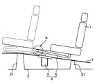
- the seat 1 is fixed to the floor surface 2 of the vehicle body via a seat rail 11.
- the seat rail 11 is for adjusting the seating position of the seat 1 in the front-rear direction of the vehicle, and includes an upper rail 111 and a lower rail 112.
- the upper rail 111 is fixed to the back surface (lower surface) of the seat surface of the seat 1.
- the lower rail 112 is fixed to the cross member 21 provided on the floor surface 2.
- the upper rail 111 is slidable in the front-rear direction with respect to the lower rail 112.
- the indoor air-conditioning unit 3 in the vehicle air conditioner for air-conditioning the vehicle interior space is arranged inside the instrument panel (instrument panel) at the foremost part of the vehicle interior.
- the indoor air-conditioning unit 3 includes an air-conditioning case that houses therein various air-conditioning equipment such as a blower, an evaporator of a refrigeration cycle, and a heater core.
- various air-conditioning equipment such as a blower, an evaporator of a refrigeration cycle, and a heater core.
- the conditioned air adjusted to the desired temperature by the indoor air conditioning unit 3 is blown out from the air outlet into the vehicle compartment via a duct connected to the air conditioning case.
- the vehicle seat air conditioner 4 includes a seat air conditioning duct 5 and a connection duct 6.
- the seat air conditioning duct 5 guides the conditioned air adjusted to a desired temperature by the indoor air conditioning unit 3 to a position near the seat 1.
- the connection duct 6 guides the conditioned air guided through the seat air conditioning duct 5 to the seat 1.
- the seat air conditioning duct 5 has one end fixed to the indoor air conditioning unit 3 and the other end fixed to the vehicle body below the seat surface of the seat 1. Further, a portion of the seat air conditioning duct 5 that is close to the seat 1 is disposed between the floor surface 2 and the carpet 7.
- connection duct 6 has one end fixed to the seat air conditioning duct 5 and the other end fixed to the back surface (lower surface) of the seat surface of the seat 1. As shown in FIG. 2, the connection duct 6 is arranged in a state where the intermediate portion is bent in a U shape, and the position of the bent portion bent at the intermediate portion is displaced as the seat 1 moves. It is supposed to be.
- the air blower of the vehicle seat air conditioner 4 is built in the seat surface of the seat 1.
- the conditioned air sucked in by the blower is blown out from the surface of the seat surface through an air passage formed inside the seat surface and an air blowing hole formed in the surface of the seat surface.
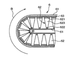
- connection duct 6 includes a duct main body (outer skin portion) 61, a plurality of core members 62, and a connecting member 63.
- the duct main body 61 is formed in a cylindrical shape by a thin film made of a flexible material such as vinyl or rubber. Air conditioned air circulates inside the duct body 61.
- the core member 62 is made of a material having higher rigidity than the material of the duct body 61, for example, a resin.
- the core member 62 includes an outer peripheral plate portion 621, an inner peripheral plate portion 622, and a plurality of connecting plate portions 623.
- the outer peripheral plate portion 621 has a plate shape and is located on the outer peripheral side in the bent portion.
- the inner peripheral plate portion 622 has a plate shape and is located on the inner peripheral side in the bent portion.
- the plurality of connecting plate portions 623 have a plate shape and connect the outer peripheral plate portion 621 and the inner peripheral plate portion 622.
- the outer peripheral plate portion 621 and the inner peripheral plate portion 622 are arranged to face each other with a predetermined interval.
- the cross-sectional shape of the cross section orthogonal to the air flow direction B of the core material 62 is rectangular.
- the outer peripheral plate portion 621, the inner peripheral plate portion 622, and the connecting plate portion 623 form a plurality of openings 624 that allow the conditioned air to pass therethrough.
- the length of the outer peripheral plate portion 621 in the flow direction B is longer than the length of the inner peripheral plate portion 622 in the flow direction B.
- the connecting plate portion 623 has a trapezoidal shape in a cross section perpendicular to the flow direction B. More specifically, the length of the connecting plate portion 623 in the flow direction B on the outer peripheral plate portion 621 side is longer than the length of the connecting plate portion 623 in the flow direction B on the inner peripheral plate portion 622 side.
- the connecting member 63 is formed into a film shape with a flexible material such as vinyl or rubber.
- the connecting member 63 is joined to the outer surface side of the outer peripheral plate portion 621 by bonding or the like, and connects the plurality of core members 62. More specifically, the plurality of core members 62 are arranged between adjacent outer peripheral plate portions 621 with a predetermined gap ⁇ along the flow direction B, and are connected by a connecting member 63.
- the integrated core member 62 and connecting member 63 are inserted into the duct body 61 such that a plurality of core members 62 are arranged along the flow direction B.
- the outer surfaces of the core member 62 and the connecting member 63 are in close contact with the inner surface of the duct body 61.
- the cross-sectional shape of the cross section orthogonal to the flow direction B of the duct main body 61 is maintained in a predetermined shape by the connecting member 63 having higher rigidity than the duct main body 61.
- the cross-sectional shape of the duct body 61 is rectangular like the core material 62.
- connection duct 6 configured by inserting the core member 62 and the connecting member 63 into the duct main body 61 is fixed to the seat air-conditioning duct 5 and the other end is the back surface of the seat surface of the seat 1 ( It is fixed to the lower surface and is arranged in a state where the middle part is bent in a U-shape.
- FIG. 7 shows a bent portion bent into a U-shape.
- the duct body 61 is easily bent because it is made of a highly flexible material.
- the core members 62 are arranged with a gap ⁇ between adjacent outer peripheral plate portions 621, and are connected by a connecting member 63 made of a material having high flexibility. As a result, the integrated core member 62 and connecting member 63 can be easily bent.
- the inner peripheral side portion of the duct main body 61 is in a slack state at the bent portion, and the connecting duct 6 can be easily bent until the adjacent inner peripheral plate portions 622 come into contact with each other or are close to each other. it can.
- connection duct 6 since the connection duct 6 can be easily bent, the bending radius R of the bent portion can be made smaller than that in which the bellows portion is bent as in the prior art. The vertical dimension of the connecting duct 6 in the bent state can be reduced.
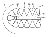
- the connection duct 8 has an outer peripheral plate portion 81 and an inner peripheral plate portion 82.
- the outer peripheral plate portion 81 has a plate shape and is located on the outer peripheral side in the bent portion.
- the inner peripheral plate portion 82 has a plate shape and is located on the inner peripheral side in the bent portion.
- the outer peripheral plate portion 81 and the inner peripheral plate portion 82 face each other with a predetermined interval in a direction orthogonal to the flow direction B.
- the outer peripheral plate portion 81 is thicker than the inner peripheral plate portion 82. Therefore, the outer peripheral plate portion 81 is higher in rigidity than the inner peripheral plate portion 82.
- the first side plate is thinner and less rigid than the outer peripheral plate portion 81 at both ends of the outer peripheral plate portion 81 and the inner peripheral plate portion 82 in the direction orthogonal to the flow direction B.
- the second side plate 84 having a thickness greater than that of the portion 83 and the first side plate 83 and having a higher rigidity is disposed.
- the first side surface plate portion 83 has a trapezoidal shape or a triangular shape in a cross section perpendicular to the flow direction B.
- the length of the first side surface plate portion 83 in the flow direction B becomes longer as it approaches the inner peripheral plate portion 82 from the outer peripheral plate portion 81.
- the second side face plate portion 84 has a trapezoidal shape or a triangular shape in a cross section perpendicular to the flow direction B. In other words, the second side surface plate portion 84 becomes shorter as the length in the flow direction B approaches the inner peripheral plate portion 82 from the outer peripheral plate portion 81.
- first side plate portions 83 and the second side plate portions 84 are alternately arranged along the flow direction B.
- connection duct 8 is formed in a cylindrical shape by the outer peripheral plate portion 81, the inner peripheral plate portion 82, the first side face plate portion 83, and the second side face plate portion 84, and the conditioned air flows through the inside. ing. Further, the connection duct 8 has a rectangular cross-sectional shape orthogonal to the flow direction B.
- a reinforcing plate 85 having a thickness greater than that of the first side plate 83 and a higher rigidity is provided at a portion of the connection duct 8 where the conditioned air flows.
- the reinforcing plate portion 85 has a trapezoidal or triangular shape in a cross section perpendicular to the flow direction B, and the length in the flow direction B becomes shorter as it approaches the inner peripheral plate portion 82 from the outer peripheral plate portion 81.
- the reinforcing plate portion 85 and the second side plate portion 84 are disposed so as to overlap when viewed from a direction orthogonal to the flow direction B.
- the outer peripheral plate portion 81 is formed with a hollow portion, and a thin portion 86 having the same plate thickness as the inner peripheral plate portion 82 is provided. When viewed from a direction orthogonal to the flow direction B, the thin portion 86 and the top of the first side plate portion 83 are at the same position.
- connection duct 8 is made of a flexible material such as rubber, and includes an outer peripheral plate portion 81, an inner peripheral plate portion 82, a first side plate portion 83, a second side plate portion 84, a reinforcing plate portion 85, and a thin portion. 86 is integrally molded.
- the outer peripheral plate portion 81, the second side plate portion 84, and the reinforcing plate portion 85 have, for example, a plate thickness of 2 mm
- the inner peripheral plate portion 82, the first side plate portion 83, and the thin portion 86 have, for example, a plate thickness of 0. .5 mm.
- connection duct 8 configured as described above has one end fixed to the seat air-conditioning duct 5 (see FIG. 2), the other end fixed to the back surface (lower surface) of the seat surface of the seat 1 (see FIG. 2), and an intermediate portion U Arranged in a bent state.
- the inner peripheral plate portion 82 and the thin portion 86 are thin in thickness and low in rigidity, they can be easily bent. Therefore, as shown in FIG. 11, the inner peripheral plate portion 82 is in a slack state at the bent portion, and the connection duct 8 can be easily bent until the adjacent second side face plate portions 84 abut or approach each other.
- connection duct 8 in the bent state can be reduced as in the first embodiment.
- connection duct 8 since the cross-sectional shape of the connection duct 8 is maintained in a predetermined shape with the second side face plate portion 84 and the reinforcing plate portion 85 as a support, it is possible to prevent the flow path from being blocked due to the buckling of the connection duct 8. (Other embodiments) Note that the present disclosure is not limited to the above-described embodiment, and can be appropriately changed without departing from the gist of the present disclosure.
- the rigidity of each part of the connection duct 8 is changed by changing the plate thickness.
- the rigidity of each part of the connection duct 8 may be changed by molding the connection duct 8 in two colors using rubbers having different hardnesses.
Landscapes
- Engineering & Computer Science (AREA)
- Mechanical Engineering (AREA)
- Aviation & Aerospace Engineering (AREA)
- Transportation (AREA)
- Physics & Mathematics (AREA)
- Thermal Sciences (AREA)
- Power Engineering (AREA)
- Air-Conditioning For Vehicles (AREA)
Abstract
接続ダクト(6)は、可撓性に富む材料にて形成され、空調風が流通するダクト本体(61)と、ダクト本体(61)よりも剛性の高い材料にて形成され、ダクト本体内に空気の流れ方向(B)に沿って複数個配置されてダクト本体(61)の断面形状を所定形状に維持する芯材(62)とを備えている。芯材(62)は、曲がり部において外周側に位置する外周板部(621)と、曲がり部において内周側に位置する内周板部(622)と、外周板部(621)と内周板部(622)とを連結する連結板部(623)とを備える。外周板部(621)の流れ方向(B)の長さは、内周板部(622)の流れ方向(B)の長さよりも長くなっている。
Description
本出願は、当該開示内容が参照によって本出願に組み込まれた、2013年11月18日に出願された日本特許出願2013-237987号を基にしている。
本開示は、室内空調ユニットから供給される空調風をシートから吹き出す車両用シート空調装置に関するものである。
従来、この種の車両用シート空調装置として、例えば特許文献1に記載されたものがある。この特許文献1に記載された車両用シート空調装置は、室内空調ユニットから供給される空調風をシートの近傍まで導くシート空調ダクトと、一端がシート空調ダクトに固定され、他端がシートに固定されて、空調風をシートに導く接続ダクトとを備えている。
接続ダクトは、シートの移動に対応するために、蛇腹状の部位(以下、蛇腹部という)を備え、蛇腹部を直線的に配置し、シートの移動に伴って蛇腹部を伸縮させるようになっている。
また、他の構成の接続ダクトは、蛇腹部をU字状に曲げて配置し、シートの移動に伴って蛇腹部を伸縮・変形させるようになっている。
しかしながら、車種によってはシートスライド量が非常に長いものがある。そのため、接続ダクトの蛇腹部を直線的に配置した車両用シート空調装置では、蛇腹部が最短時は成立しても最長時は成立しないおそれがある。すなわち、伸びきってしまい、内部の空気通路が閉塞するおそれがある。或いは、蛇腹部が最長時は成立しても最短時は成立しないおそれがある。すなわち、蛇腹が嵩張って縮まないおそれがある。仮に、蛇腹の山谷を大きくすれば成立するが、このようにすると体格が大きくなるため、シート下のスペースが小さい場合は(例えば、上下方向の寸法が30mm程度)、シート下に収納できなくなる。
接続ダクトの蛇腹部をU字状に曲げて配置した車両用シート空調装置では、シートスライド量が大きくても対応しやすい。しかしながら、曲げ半径が大きくなるためシート下のスペースに納まらず、また、曲げ半径が小さくなると座屈して内部の空気通路が閉塞しやすくなるおそれがある。
本開示は上記点に鑑みて、接続ダクトの上下方向の寸法を小さくすることが可能な、接続ダクトを曲げて配置する車両用シート空調装置を提供することを目的とする。
本開示の第1態様に係る車両用シート空調装置は、車室内空間を空調する室内空調ユニットから供給される空調風をシートから吹き出す車両用シート空調装置である。当該車両用シート空調装置は、一端が室内空調ユニットに連通され、他端がシートの近傍位置に配置されて、空調風をシートの近傍位置まで導くシート空調ダクトと、一端がシート空調ダクトに連通され、他端がシートに連通されて、空調風をシートに導くとともに、中間部で曲げられた曲がり部の位置がシートの移動に伴って変位する接続ダクトとを備える。接続ダクトは、可撓性に富む材料にて形成され、空調風が流通するダクト本体と、ダクト本体よりも剛性の高い材料にて形成され、ダクト本体内に空気の流れ方向に沿って複数個配置されてダクト本体の断面形状を所定形状に維持する芯材とを備える。芯材は、曲がり部において外周側に位置する外周板部と、曲がり部において内周側に位置する内周板部と、外周板部と内周板部とを連結する連結板部とを備える。外周板部における流れ方向の長さは、内周板部における流れ方向の長さよりも長くなっている。
これによると、接続ダクトは、隣接する内周板部同士が当接ないしは近接するまで容易に曲がることができる。したがって、従来のように蛇腹部を曲げて配置するものよりも、曲がり部の曲げ半径を小さくすることができ、曲げた状態での接続ダクトの上下方向の寸法を小さくすることができる。
また、芯材が支えとなってダクト本体の断面形状が所定形状に維持されるため、接続ダクトの座屈による流路閉塞を防止することができる。
あるいは、本開示の第2態様に係る車両用シート空調装置は、車室内空間を空調する室内空調ユニットから供給される空調風をシートから吹き出す車両用シート空調装置である。当該車両用シート空調装置は、一端が室内空調ユニットに連通され、他端がシートの近傍位置に配置されて、空調風をシートの近傍位置まで導くシート空調ダクトと、一端がシート空調ダクトに連通され、他端がシートに連通されて、空調風をシートに導くとともに、中間部で曲げられた曲がり部の位置がシートの移動に伴って変位する接続ダクトとを備える。接続ダクトは、可撓性に富む材料にて筒状に形成されるとともに、曲がり部において外周側に位置する外周板部の剛性が、曲がり部において内周側に位置する内周板部の剛性よりも高くなっている。
これによると、剛性が相対的に低い内周板部側が曲がりやすいため、従来のように蛇腹部を曲げて配置するものよりも、曲がり部の曲げ半径を小さくすることができ、曲げた状態での接続ダクトの上下方向の寸法を小さくすることができる。
以下、本開示の実施形態について図に基づいて説明する。なお、以下の各実施形態相互において、互いに同一もしくは均等である部分には、図中、同一符号を付してある。
(第1実施形態)
本開示の第1実施形態について説明する。
(第1実施形態)
本開示の第1実施形態について説明する。
図1、図2に示すように、シート1は、シートレール11を介して車体の床面2に固定されている。シートレール11は、シート1の着座位置を車両の前後方向に調整するためのものであり、アッパーレール111とロアレール112とを有している。アッパーレール111は、シート1の座面の裏面(下面)に固定されている。ロアレール112は、床面2に設けられたクロスメンバ21に固定されている。アッパーレール111は、ロアレール112に対して前後方向に摺動可能になっている。
車室内空間を空調するための車両用空調装置における室内空調ユニット3が、車室内最前部の計器盤(インストルメントパネル)の内側に配置されている。室内空調ユニット3は、送風機、冷凍サイクルの蒸発器およびヒータコア等の各種空調機器をその内部に収容する空調ケースを備える。そして、室内空調ユニット3で所望温度に調整された空調風は、空調ケースに接続されたダクトを介して吹出口から車室内に吹き出される。
車両用シート空調装置4は、シート空調ダクト5と接続ダクト6を備える。シート空調ダクト5は、室内空調ユニット3で所望温度に調整された空調風をシート1の近傍位置まで導く。接続ダクト6は、シート空調ダクト5を介して導かれた空調風をシート1に導く。
シート空調ダクト5は、一端が室内空調ユニット3に固定され、他端がシート1の座面の下方にて車体に固定されている。また、シート空調ダクト5のうちシート1に近い部位は、床面2とカーペット7との間に配置されている。
接続ダクト6は、一端がシート空調ダクト5に固定され、他端がシート1の座面の裏面(下面)に固定されている。また、図2に示すように、接続ダクト6は、中間部がU字状に曲げられた状態で配置されており、中間部で曲げられた曲がり部の位置がシート1の移動に伴って変位するようになっている。
車両用シート空調装置4の送風機は、シート1の座面に内蔵されている。送風機により吸い込まれた空調風は、座面の内部に形成された空気通路、および座面の表面に形成された空気吹出穴を通じて座面の表面から吹き出される。
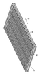
図3~図7に示すように、接続ダクト6は、ダクト本体(外皮部)61と、複数の芯材62と、連結部材63とを備えている。
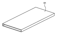
図4に示すように、ダクト本体61は、ビニールやゴム等の可撓性に富む材料よりなる薄膜によって、筒状に形成されている。ダクト本体61の内部を空調風が流通する。
図5、図6に示すように、芯材62は、ダクト本体61の材料よりも剛性の高い材料、例えば樹脂にて形成されている。
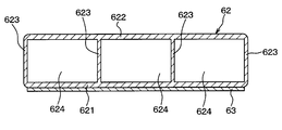
また、芯材62は、外周板部621と、内周板部622と、複数の連結板部623とを備えている。外周板部621は板状を有し、曲がり部において外周側に位置する。内周板部622は板状を有し、曲がり部において内周側に位置する。複数の連結板部623は板状を有し、外周板部621と内周板部622とを連結する。
外周板部621と内周板部622は所定の間隔をもって対向して配置されている。芯材62の空気の流れ方向Bに直交する断面の断面形状は矩形状になっている。そして、外周板部621と内周板部622と連結板部623とによって、空調風を通過させる複数の開口部624が形成されている。
外周板部621の流れ方向Bの長さは、内周板部622の流れ方向Bの長さよりも長くなっている。
連結板部623は、流れ方向Bに直交する断面において、台形状になっている。より詳細には、連結板部623における外周板部621側の流れ方向Bの長さが、連結板部623における内周板部622側の流れ方向Bの長さよりも長くなっている。
連結部材63は、ビニールやゴム等の可撓性に富む材料にて、膜状に形成されている。連結部材63は、外周板部621における外面側に接着等にて接合されて、複数の芯材62を連結している。より詳細には、複数の芯材62は、隣接する外周板部621間に、流れ方向Bに沿って所定の隙間δを空けて並び、連結部材63によって連結されている。
図3に示すように、一体化された芯材62と連結部材63は、複数の芯材62が流れ方向Bに沿って並ぶようにして、ダクト本体61内に挿入される。芯材62および連結部材63の外面がダクト本体61の内面に略密着する。これにより、ダクト本体61よりも剛性が高い連結部材63により、ダクト本体61の流れ方向Bに直交する断面の断面形状が所定形状に維持されるようになっている。具体的には、ダクト本体61のその断面形状は、芯材62と同様に矩形状になる。
芯材62と連結部材63をダクト本体61内に挿入して構成された接続ダクト6は、前述したように、一端がシート空調ダクト5に固定され、他端がシート1の座面の裏面(下面)に固定され、中間部がU字状に曲げられた状態で配置される。なお、図7は、U字状に曲げられた曲がり部を示している。
ここで、ダクト本体61は、可撓性に富む材料よりなるため、容易に曲がる。また、芯材62は隣接する外周板部621間に隙間δを空けて並び、可撓性に富む材料よりなる連結部材63によって連結されている。これにより、一体化された芯材62と連結部材63は、容易に曲がることができる。
したがって、図7に示すように、ダクト本体61における内周側部位は曲がり部において弛んだ状態となり、接続ダクト6は隣接する内周板部622同士が当接ないしは近接するまで容易に曲がることができる。
そして、図2に示すように、シート1が例えば実線で示す位置から破線で示す位置に移動されると、当接ないしは近接する内周板部622が順次変わって、接続ダクト6の曲がり部の位置がシート1の移動に伴って変位する。
以上述べたように、本実施形態では、接続ダクト6は容易に曲がることができるため、従来のように蛇腹部を曲げて配置するものよりも、曲がり部の曲げ半径Rを小さくすることができ、曲げた状態での接続ダクト6の上下方向の寸法を小さくすることができる。
また、芯材62が支えとなってダクト本体61の断面形状が所定形状に維持されるため、接続ダクト6の座屈による流路閉塞を防止することができる。
(第2実施形態)
本開示の第2実施形態について説明する。本実施形態は、接続ダクトの構成が第1実施形態と異なっている。その他に関しては第1実施形態と同様であるため、第1実施形態と異なる部分についてのみ説明する。
(第2実施形態)
本開示の第2実施形態について説明する。本実施形態は、接続ダクトの構成が第1実施形態と異なっている。その他に関しては第1実施形態と同様であるため、第1実施形態と異なる部分についてのみ説明する。
図8~図11に示すように、接続ダクト8は、外周板部81と内周板部82を有する。外周板部81は板状を有し、曲がり部において外周側に位置する。内周板部82は板状を有し、曲がり部において内周側に位置する。外周板部81と内周板部82は、流れ方向Bと直交する方向において所定の間隔を空けて対向している。外周板部81は内周板部82よりも板厚が厚い。したがって、外周板部81は内周板部82よりも剛性が高くなっている。
図9、10で示すように、外周板部81および内周板部82における流れ方向Bに直交する方向の両端には、外周板部81よりも板厚が薄く且つ剛性が低い第1側面板部83、および第1側面板部83よりも板厚が厚く且つ剛性が高い第2側面板部84が配置されている。
より詳細には、第1側面板部83は、流れ方向Bに直交する断面において台形または三角形を有している。換言すれば、第1側面板部83は、流れ方向Bの長さが外周板部81から内周板部82に近づくほど長くなっている。
また、第2側面板部84は、流れ方向Bに直交する断面において台形または三角形を有している。換言すれば、第2側面板部84は、流れ方向Bの長さが外周板部81から内周板部82に近づくほど短くなっている。
さらに、第1側面板部83および第2側面板部84は、流れ方向Bに沿って交互に配置されている。
そして、接続ダクト8は、外周板部81、内周板部82、第1側面板部83、および第2側面板部84によって、筒状に形成され、内部を空調風が流通するようになっている。また、接続ダクト8は、流れ方向Bに直交する断面の形状が矩形状になっている。
接続ダクト8の空調風が流通する部位に、第1側面板部83よりも板厚が厚く且つ剛性が高い補強板部85が設けられている。この補強板部85は、流れ方向Bに直交する断面において台形または三角形の形状をしており、流れ方向Bの長さが外周板部81から内周板部82に近づくほど短くなっている。また、この補強板部85と第2側面板部84は、流れ方向Bに直交する方向から見たときに重なるように配置されている。
外周板部81には、窪み部が形成されて、内周板部82と板厚が等しい薄部86が設けられている。流れ方向Bに直交する方向から見たときに、この薄部86と第1側面板部83の頂部は、同じ位置にある。
接続ダクト8は、ゴム等の可撓性に富む材料よりなり、外周板部81、内周板部82、第1側面板部83、第2側面板部84、補強板部85、および薄部86は、一体成型されている。
なお、外周板部81、第2側面板部84、および補強板部85は、例えば板厚2mmとし、内周板部82、第1側面板部83、および薄部86は、例えば板厚0.5mmとする。
上記構成になる接続ダクト8は、一端がシート空調ダクト5(図2参照)に固定され、他端がシート1(図2参照)の座面の裏面(下面)に固定され、中間部がU字状に曲げられた状態で配置される。
ここで、内周板部82および薄部86は、板厚が薄く且つ剛性が低いため、容易に曲がることができる。したがって、図11に示すように、内周板部82は曲がり部において弛んだ状態となり、接続ダクト8は隣接する第2側面板部84同士が当接ないしは近接するまで容易に曲がることができる。
以上述べたように、本実施形態では、第1実施形態と同様に、曲げた状態での接続ダクト8の上下方向の寸法を小さくすることができる。
また、第2側面板部84および補強板部85が支えとなって接続ダクト8の断面形状が所定形状に維持されるため、接続ダクト8の座屈による流路閉塞を防止することができる。
(他の実施形態)
なお、本開示は上記した実施形態に限定されるものではなく、本開示の趣旨を逸脱しない範囲において適宜変更が可能である。
(他の実施形態)
なお、本開示は上記した実施形態に限定されるものではなく、本開示の趣旨を逸脱しない範囲において適宜変更が可能である。
例えば、第2実施形態では、接続ダクト8の各部について板厚を変えることによって剛性を変えた。しかしながら、硬度の異なるゴムを用いて接続ダクト8を2色成型することにより、接続ダクト8の各部の剛性を変えるようにしてもよい。
また、上記各実施形態は、互いに無関係なものではなく、組み合わせが明らかに不可な場合を除き、適宜組み合わせが可能である。
また、上記各実施形態において、実施形態を構成する要素は、特に必須であると明示した場合および原理的に明らかに必須であると考えられる場合等を除き、必ずしも必須のものではないことは言うまでもない。
また、上記各実施形態において、実施形態の構成要素の個数、数値、量、範囲等の数値が言及されている場合、特に必須であると明示した場合および原理的に明らかに特定の数に限定される場合等を除き、その特定の数に限定されるものではない。
また、上記各実施形態において、構成要素等の形状、位置関係等に言及するときは、特に明示した場合および原理的に特定の形状、位置関係等に限定される場合等を除き、その形状、位置関係等に限定されるものではない。
Claims (7)
- 車室内空間を空調する室内空調ユニット(3)から供給される空調風をシート(1)から吹き出す車両用シート空調装置であって、
一端が前記室内空調ユニットに連通され、他端が前記シートの近傍位置に配置されて、前記空調風を前記シートの近傍位置まで導くシート空調ダクト(5)と、
一端が前記シート空調ダクトに連通され、他端が前記シートに連通されて、前記空調風を前記シートに導くとともに、中間部で曲げられた曲がり部の位置が前記シートの移動に伴って変位する接続ダクト(6)とを備え、
前記接続ダクトは、
可撓性に富む材料にて形成され、前記空調風が流通するダクト本体(61)と、
前記ダクト本体よりも剛性の高い材料にて形成され、前記ダクト本体内に空気の流れ方向(B)に沿って複数個配置されて前記ダクト本体の断面形状を所定形状に維持する芯材(62)とを備え、
前記芯材は、
前記曲がり部において外周側に位置する外周板部(621)と、
前記曲がり部において内周側に位置する内周板部(622)と、
前記外周板部と前記内周板部とを連結する連結板部(623)とを備え、
前記外周板部における前記流れ方向の長さは、前記内周板部における前記流れ方向の長さよりも長くなっている車両用シート空調装置。 - 可撓性に富む材料にて形成され、前記外周板部に接合されて前記複数の芯材を連結する連結部材(63)をさらに備える請求項1に記載の車両用シート空調装置。
- 前記芯材は、隣接する前記外周板部間に所定の隙間(δ)をもって前記連結部材により連結されている請求項2に記載の車両用シート空調装置。
- 車室内空間を空調する室内空調ユニット(3)から供給される空調風をシート(1)から吹き出す車両用シート空調装置であって、
一端が前記室内空調ユニットに連通され、他端が前記シートの近傍に配置されて、前記空調風を前記シートの近傍位置まで導くシート空調ダクト(5)と、
一端が前記シート空調ダクトに連通され、他端が前記シートに連通されて、前記空調風を前記シートに導くとともに、中間部で曲げられた曲がり部の位置が前記シートの移動に伴って変位する接続ダクト(6)とを備え、
前記接続ダクトは、可撓性に富む材料にて形成されるとともに、前記曲がり部において外周側に位置する外周板部(81)の剛性が、前記曲がり部において内周側に位置する内周板部(82)の剛性よりも高くなっている車両用シート空調装置。 - 前記外周板部の板厚が前記内周板部の板厚よりも厚くなっている請求項4に記載の車両用シート空調装置。
- 前記外周板部および前記内周板部における空気の流れ方向(B)に直交する方向の両端に配置され、前記外周板部および前記内周板部とともに内部に空気通路を形成する側面板部(83、84)をさらに備え、
前記側面板部は、
前記外周板部よりも剛性が低く、前記流れ方向の長さが前記外周板部から前記内周板部に近づくほど長くなっている第1側面板部(83)と、
前記第1側面板部よりも剛性が高く、前記流れ方向の長さが前記外周板部から前記内周板部に近づくほど短くなっている第2側面板部(84)とを備え、
前記第1側面板部と前記第2側面板部は、前記流れ方向に沿って交互に配置されている請求項4または5に記載の車両用シート空調装置。 - 前記外周板部および前記内周板部における空気の流れ方向(B)に直交する方向の両端に配置され、前記外周板部および前記内周板部とともに内部に空気通路を形成する側面板部(83、84)をさらに備え、
前記側面板部は、
前記外周板部よりも板厚が薄く、前記流れ方向の長さが前記外周板部から前記内周板部に近づくほど長くなっている第1側面板部(83)と、
前記第1側面板部よりも板厚が厚く、前記流れ方向の長さが前記外周板部から前記内周板部に近づくほど短くなっている第2側面板部(84)とを備え、
前記第1側面板部と前記第2側面板部は、前記流れ方向に沿って交互に配置されている請求項4または5に記載の車両用シート空調装置。
Priority Applications (3)
| Application Number | Priority Date | Filing Date | Title |
|---|---|---|---|
| US15/036,671 US10137755B2 (en) | 2013-11-18 | 2014-10-30 | Vehicle seat air-conditioning device |
| DE112014005242.6T DE112014005242T5 (de) | 2013-11-18 | 2014-10-30 | Klimaanlage für einen Fahrzeugsitz |
| CN201480061496.1A CN105722704B (zh) | 2013-11-18 | 2014-10-30 | 车辆用座椅空调装置 |
Applications Claiming Priority (2)
| Application Number | Priority Date | Filing Date | Title |
|---|---|---|---|
| JP2013237987A JP6119569B2 (ja) | 2013-11-18 | 2013-11-18 | 車両用シート空調装置 |
| JP2013-237987 | 2013-11-18 |
Publications (1)
| Publication Number | Publication Date |
|---|---|
| WO2015072103A1 true WO2015072103A1 (ja) | 2015-05-21 |
Family
ID=53057056
Family Applications (1)
| Application Number | Title | Priority Date | Filing Date |
|---|---|---|---|
| PCT/JP2014/005494 Ceased WO2015072103A1 (ja) | 2013-11-18 | 2014-10-30 | 車両用シート空調装置 |
Country Status (5)
| Country | Link |
|---|---|
| US (1) | US10137755B2 (ja) |
| JP (1) | JP6119569B2 (ja) |
| CN (1) | CN105722704B (ja) |
| DE (1) | DE112014005242T5 (ja) |
| WO (1) | WO2015072103A1 (ja) |
Families Citing this family (5)
| Publication number | Priority date | Publication date | Assignee | Title |
|---|---|---|---|---|
| JP5877185B2 (ja) * | 2013-10-28 | 2016-03-02 | 本田技研工業株式会社 | 車両用冷気遮蔽構造 |
| JP6766762B2 (ja) * | 2017-06-22 | 2020-10-14 | 株式会社デンソー | シート空調システム |
| JP2019084295A (ja) * | 2017-11-10 | 2019-06-06 | トヨタ紡織株式会社 | 空調シート |
| JP2020066378A (ja) * | 2018-10-26 | 2020-04-30 | 本田技研工業株式会社 | 車両用空調装置 |
| CN113370859B (zh) * | 2021-07-30 | 2022-08-02 | 重庆长安新能源汽车科技有限公司 | 一种应用于车辆座椅的复合滑移硬管通风系统及汽车 |
Citations (4)
| Publication number | Priority date | Publication date | Assignee | Title |
|---|---|---|---|---|
| JPH0725226A (ja) * | 1993-07-08 | 1995-01-27 | Mazda Motor Corp | 車両用空調装置 |
| JP2005126063A (ja) * | 2003-10-27 | 2005-05-19 | Denso Internatl America Inc | 後席シートのための空調装置 |
| JP2010036752A (ja) * | 2008-08-06 | 2010-02-18 | Yazaki Corp | 空調用ダクト |
| JP2011185480A (ja) * | 2010-03-05 | 2011-09-22 | Totaku Industries Inc | ダクトホース |
Family Cites Families (7)
| Publication number | Priority date | Publication date | Assignee | Title |
|---|---|---|---|---|
| US3604462A (en) * | 1966-09-14 | 1971-09-14 | Owens Corning Fiberglass Corp | Flexible tubing and method of making same |
| CN2430296Y (zh) * | 2000-06-30 | 2001-05-16 | 江西新电汽车空调机有限公司 | 微型汽车冷暖空调装置 |
| JP3949396B2 (ja) * | 2001-06-12 | 2007-07-25 | 矢崎総業株式会社 | コルゲートチューブ |
| JP2007308045A (ja) | 2006-05-19 | 2007-11-29 | Valeo Thermal Systems Japan Corp | シート空調装置 |
| WO2009155632A1 (en) * | 2008-06-26 | 2009-12-30 | William James Donnelly | Flexible duct and means of production |
| JP5381834B2 (ja) * | 2010-03-17 | 2014-01-08 | 株式会社デンソー | 車両用シート空調装置 |
| CN202498984U (zh) * | 2012-01-17 | 2012-10-24 | 唐秋华 | 一种用于座椅的空调装置 |
-
2013
- 2013-11-18 JP JP2013237987A patent/JP6119569B2/ja not_active Expired - Fee Related
-
2014
- 2014-10-30 DE DE112014005242.6T patent/DE112014005242T5/de not_active Withdrawn
- 2014-10-30 US US15/036,671 patent/US10137755B2/en not_active Expired - Fee Related
- 2014-10-30 WO PCT/JP2014/005494 patent/WO2015072103A1/ja not_active Ceased
- 2014-10-30 CN CN201480061496.1A patent/CN105722704B/zh not_active Expired - Fee Related
Patent Citations (4)
| Publication number | Priority date | Publication date | Assignee | Title |
|---|---|---|---|---|
| JPH0725226A (ja) * | 1993-07-08 | 1995-01-27 | Mazda Motor Corp | 車両用空調装置 |
| JP2005126063A (ja) * | 2003-10-27 | 2005-05-19 | Denso Internatl America Inc | 後席シートのための空調装置 |
| JP2010036752A (ja) * | 2008-08-06 | 2010-02-18 | Yazaki Corp | 空調用ダクト |
| JP2011185480A (ja) * | 2010-03-05 | 2011-09-22 | Totaku Industries Inc | ダクトホース |
Also Published As
| Publication number | Publication date |
|---|---|
| DE112014005242T5 (de) | 2016-09-08 |
| JP6119569B2 (ja) | 2017-04-26 |
| CN105722704B (zh) | 2017-08-08 |
| CN105722704A (zh) | 2016-06-29 |
| US20160288612A1 (en) | 2016-10-06 |
| US10137755B2 (en) | 2018-11-27 |
| JP2015098215A (ja) | 2015-05-28 |
Similar Documents
| Publication | Publication Date | Title |
|---|---|---|
| WO2015072103A1 (ja) | 車両用シート空調装置 | |
| CN104097486B (zh) | 具有柔性叶片的空气管道组件 | |
| JP5935769B2 (ja) | 車両用空調装置 | |
| JP5568642B2 (ja) | 車両用空気調和装置 | |
| WO2016002128A1 (ja) | 車両用シート空調装置 | |
| JP5568408B2 (ja) | 車両用空気調和装置 | |
| WO2015059865A1 (ja) | 空調装置 | |
| JP6248815B2 (ja) | 車両用シート空調装置 | |
| JP2011207342A (ja) | 車両用補強構造体 | |
| CN102162676B (zh) | 车辆用空调装置 | |
| JP5276307B2 (ja) | 車両用空調装置 | |
| JP6311371B2 (ja) | 車両の空調装置 | |
| JP6020352B2 (ja) | ダクト装置 | |
| JP2011093499A (ja) | インストルメントパネル構造 | |
| JP2012131356A (ja) | シート空調装置 | |
| JP2017087746A (ja) | 乗物用シート | |
| JP6019783B2 (ja) | 車両の空調ダクト | |
| JP5901205B2 (ja) | 車両用空気調和装置のダンパ装置 | |
| JP2008081025A (ja) | 通風ダクト | |
| JP2011057044A (ja) | スライドダンパ装置 | |
| JP4530757B2 (ja) | ダクト装置 | |
| JP6801478B2 (ja) | 空調装置 | |
| JP4246143B2 (ja) | 車両用空調ダクト | |
| JP2018122678A (ja) | インパネメンバ | |
| JP2014224643A (ja) | 送風装置 |
Legal Events
| Date | Code | Title | Description |
|---|---|---|---|
| 121 | Ep: the epo has been informed by wipo that ep was designated in this application |
Ref document number: 14862703 Country of ref document: EP Kind code of ref document: A1 |
|
| WWE | Wipo information: entry into national phase |
Ref document number: 15036671 Country of ref document: US |
|
| WWE | Wipo information: entry into national phase |
Ref document number: 112014005242 Country of ref document: DE |
|
| 122 | Ep: pct application non-entry in european phase |
Ref document number: 14862703 Country of ref document: EP Kind code of ref document: A1 |