WO2015072088A1 - 膨脹弁 - Google Patents
膨脹弁 Download PDFInfo
- Publication number
- WO2015072088A1 WO2015072088A1 PCT/JP2014/005357 JP2014005357W WO2015072088A1 WO 2015072088 A1 WO2015072088 A1 WO 2015072088A1 JP 2014005357 W JP2014005357 W JP 2014005357W WO 2015072088 A1 WO2015072088 A1 WO 2015072088A1
- Authority
- WO
- WIPO (PCT)
- Prior art keywords
- expansion valve
- block
- refrigerant
- pressure
- refrigerant passage
- Prior art date
- Legal status (The legal status is an assumption and is not a legal conclusion. Google has not performed a legal analysis and makes no representation as to the accuracy of the status listed.)
- Ceased
Links
Images






Classifications
-
- F—MECHANICAL ENGINEERING; LIGHTING; HEATING; WEAPONS; BLASTING
- F16—ENGINEERING ELEMENTS AND UNITS; GENERAL MEASURES FOR PRODUCING AND MAINTAINING EFFECTIVE FUNCTIONING OF MACHINES OR INSTALLATIONS; THERMAL INSULATION IN GENERAL
- F16K—VALVES; TAPS; COCKS; ACTUATING-FLOATS; DEVICES FOR VENTING OR AERATING
- F16K31/00—Actuating devices; Operating means; Releasing devices
- F16K31/12—Actuating devices; Operating means; Releasing devices actuated by fluid
-
- F—MECHANICAL ENGINEERING; LIGHTING; HEATING; WEAPONS; BLASTING
- F25—REFRIGERATION OR COOLING; COMBINED HEATING AND REFRIGERATION SYSTEMS; HEAT PUMP SYSTEMS; MANUFACTURE OR STORAGE OF ICE; LIQUEFACTION SOLIDIFICATION OF GASES
- F25B—REFRIGERATION MACHINES, PLANTS OR SYSTEMS; COMBINED HEATING AND REFRIGERATION SYSTEMS; HEAT PUMP SYSTEMS
- F25B41/00—Fluid-circulation arrangements
- F25B41/30—Expansion means; Dispositions thereof
- F25B41/31—Expansion valves
- F25B41/33—Expansion valves with the valve member being actuated by the fluid pressure, e.g. by the pressure of the refrigerant
- F25B41/335—Expansion valves with the valve member being actuated by the fluid pressure, e.g. by the pressure of the refrigerant via diaphragms
-
- F—MECHANICAL ENGINEERING; LIGHTING; HEATING; WEAPONS; BLASTING
- F25—REFRIGERATION OR COOLING; COMBINED HEATING AND REFRIGERATION SYSTEMS; HEAT PUMP SYSTEMS; MANUFACTURE OR STORAGE OF ICE; LIQUEFACTION SOLIDIFICATION OF GASES
- F25B—REFRIGERATION MACHINES, PLANTS OR SYSTEMS; COMBINED HEATING AND REFRIGERATION SYSTEMS; HEAT PUMP SYSTEMS
- F25B2341/00—Details of ejectors not being used as compression device; Details of flow restrictors or expansion valves
- F25B2341/06—Details of flow restrictors or expansion valves
- F25B2341/068—Expansion valves combined with a sensor
- F25B2341/0683—Expansion valves combined with a sensor the sensor is disposed in the suction line and influenced by the temperature or the pressure of the suction gas
Definitions
- the present disclosure relates to an expansion valve applied to a vapor compression refrigeration cycle.
- This type of expansion valve includes a power element portion that operates to be displaced according to the temperature and pressure of the refrigerant flowing out of the evaporator, and a throttle passage that decompresses and expands the high-pressure refrigerant by displacing the valve body by the power element portion. The opening of the passage is adjusted.
- the power element portion forms a sealed space in which a diaphragm that is displaced according to the pressure received at the pressure receiving surface and a temperature-sensitive medium whose pressure changes according to the temperature is sealed by bonding with the diaphragm. It is composed of an upper lid member and the like. And the displacement of a diaphragm is transmitted to a valve body via an operating rod, so that the passage opening of the throttle passage is adjusted.
- a general expansion valve causes a refrigerant passage for introducing high-pressure refrigerant, a throttle passage for decompressing and expanding high-pressure refrigerant, and a refrigerant flowing out of an evaporator to flow inside a body constituted by a single metal block or the like.
- a refrigerant passage or the like is formed.
- a valve mechanism such as a valve body and an operating rod is accommodated inside the body, and a part of the power element portion is arranged outside the body.
- the means for adjusting the opening degree of the throttle passage (valve mechanism) and the means for detecting the temperature and pressure of the refrigerant flowing out from the evaporator (power element portion) can be integrated.
- the pressure of the temperature sensitive medium is easily affected by the external ambient temperature. If the temperature sensitive medium changes according to the external ambient temperature, the opening degree of the throttle passage fluctuates accordingly, and there is a problem that the efficiency of the refrigeration cycle is lowered and the operation becomes unstable.
- the refrigerant flowing out of the evaporator and the pressure in the enclosed space act on the diaphragm, and the external pressure (atmospheric pressure) and the pressure in the enclosed space act on the upper lid member and the like.
- a force tensile force
- a force that separates the joint between the diaphragm and the upper lid member or the like may act due to the pressure of the refrigerant, and there is a problem that it is difficult to sufficiently secure the airtightness of the enclosed space.
- the transmission member (operating rod) that transmits the displacement of the power element portion to the valve body crosses (intersects) the refrigerant passage through which the refrigerant that has flowed out of the evaporator flows inside the body. Has been placed. For this reason, the flow of the refrigerant flowing out of the evaporator is disturbed by the transmission member or the like inside the body, and there is a problem that abnormal noise occurs or noise increases due to the disturbance of the refrigerant. is there.
- the passage cross-sectional area and passage shape of the refrigerant passage through which the refrigerant flowing out of the evaporator flows may be changed due to a change in the specification of the refrigeration cycle. For example, when the flow rate of the low-pressure refrigerant flowing out from the evaporator is large, the inner diameter of the refrigerant passage through which the refrigerant flowing out from the evaporator flows may be increased in order to reduce the pressure loss inside the expansion valve.
- the body forming the outer shell is composed of a single metal block, it is necessary to prepare a body that satisfies the specifications whenever the specifications of the refrigeration cycle are changed. . That is, in the conventional expansion valve, it is necessary to prepare a body and parts suitable for the body every time the refrigeration cycle specifications are changed, and the number of components of the expansion valve is remarkably increased. There are challenges.
- JP 2012-197990 A (corresponding to EP2503267A2)
- This indication aims at providing the expansion valve which can solve at least one of the subject mentioned above in view of the above-mentioned point.
- the present disclosure is applied to a vapor compression refrigeration cycle, and is intended for an expansion valve that decompresses and expands the high-pressure refrigerant flowing in the refrigeration cycle and flows the decompressed and expanded low-pressure refrigerant to the refrigerant inlet side of the evaporator.
- the first refrigerant passage through which high-pressure refrigerant flows, the second refrigerant passage through which low-pressure refrigerant decompressed and expanded flows out to the refrigerant inlet side of the evaporator, and the outflow from the evaporator
- the body includes a first block having a first refrigerant passage and a second refrigerant passage formed therein, and a second block having a third refrigerant passage formed therein.
- the second block has an internal space (50a) into which the low-pressure refrigerant flowing through one of the second refrigerant passage and the third refrigerant passage is introduced between the second block and the first block when assembled to the first block.
- the valve mechanism is accommodated in the first block, and the power element portion is accommodated in the internal space.
- the power element portion that drives the valve mechanism is accommodated in an internal space formed between the first block and the second block.
- the pressure of the temperature sensitive medium is hardly affected by the external ambient temperature
- the refrigeration cycle is affected by the external ambient temperature as compared with the conventional technology in which a part of the power element part is exposed to the outside. It is possible to suppress a decrease in efficiency and an unstable operation.
- the pressure of the refrigerant existing in the internal space acts to compress the outer periphery of the power element portion. For this reason, even if the strength of the joint between the diaphragm and the space forming member is low, the airtightness of the enclosed space is improved as compared with the conventional technique in which the pressure of the refrigerant acts in the direction of separating the joint between the diaphragm and the space forming member. It can be secured sufficiently.
- the first block in which the first and second refrigerant passages are formed and the valve mechanism is accommodated is separated from the second block in which the third refrigerant passage is formed.
- the passage sectional area and the passage shape of the third refrigerant passage are changed due to the specification change of the refrigeration cycle, etc.
- the passage sectional area and the passage of the third refrigerant passage of the second block are not changed as a whole body. This can be dealt with by changing the shape or the like.
- the first block can be used in common regardless of the specification of the refrigeration cycle, the versatility of the expansion valve is improved.
- the valve mechanism for adjusting the flow rate of the refrigerant flowing out to the refrigerant inlet side of the evaporator is configured to be accommodated in the first block, so that the valve mechanism is formed in the second block. There is no hindrance to the refrigerant flowing through the refrigerant passage. As a result, compared to the prior art in which a part of the valve mechanism is interposed inside the third refrigerant passage, it is possible to suppress the generation of noise and noise caused by the disturbance of the refrigerant flowing through the third refrigerant passage.
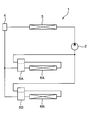
- FIG. 1 is an overall configuration diagram of a refrigeration cycle according to the first embodiment of the present disclosure.
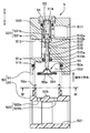
- FIG. 2 is a vertical sectional view of the expansion valve according to the first embodiment.
- FIG. 3 is an exploded view of the expansion valve according to the first embodiment.
- 4 is a cross-sectional view showing a cross section taken along line IV-IV shown in FIG.
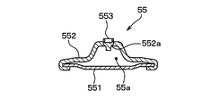
- FIG. 5 is a cross-sectional view of the power element portion of the expansion valve according to the first embodiment.
- FIG. 6 is a vertical cross-sectional view of an expansion valve according to Modification 1 of the first embodiment.
- FIG. 7 is a vertical cross-sectional view of an expansion valve according to Modification 2 of the first embodiment.
- FIG. 8 is an arrow view of the expansion valve as seen from the direction of arrow X in FIG. FIG.
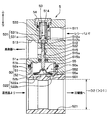
- FIG. 9 is a vertical cross-sectional view of an expansion valve according to a second embodiment of the present disclosure.
- FIG. 10 is a vertical sectional view showing a modification of the expansion valve according to the second embodiment.
- FIG. 11 is a vertical cross-sectional view of an expansion valve according to a third embodiment of the present disclosure.
- FIG. 12 is a vertical sectional view showing a modification of the expansion valve according to the third embodiment.
- FIG. 13 is an overall configuration diagram of a refrigeration cycle according to the fourth embodiment of the present disclosure.
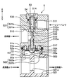
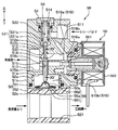
- FIG. 14 is a vertical cross-sectional view of the expansion valve according to the fourth embodiment.
- FIG. 15 is a vertical cross-sectional view showing a main part of the expansion valve according to the fourth embodiment.
- the expansion valve 5 of the present disclosure is applied to a vapor compression refrigeration cycle 1 used in an air conditioner mounted on a vehicle.
- the refrigeration cycle 1 includes a compressor 2, a radiator 3, a liquid receiver 4, an expansion valve 5, and an evaporator 6 as main components.
- the compressor 2 obtains driving force from an unillustrated vehicle running engine via an electromagnetic clutch or the like, and sucks and compresses the refrigerant.
- the compressor 2 may be comprised with the electric compressor driven with the driving force output from an electric motor.
- the heat radiator 3 is a heat exchanger that causes heat exchange between the high-pressure refrigerant discharged from the compressor 2 and outside air (air outside the passenger compartment) blown by a cooling fan (not shown) to dissipate and condense the high-pressure refrigerant.
- a liquid receiver (receiver) 4 Connected to the refrigerant outlet side of the radiator 3 is a liquid receiver (receiver) 4 that separates the high-pressure refrigerant flowing out of the radiator 3 into a gas-phase refrigerant and a liquid-phase refrigerant and accumulates excess liquid-phase refrigerant in the cycle.
- an expansion valve 5 is connected to the outlet side of the liquid phase refrigerant of the receiver 4.
- the expansion valve 5 is a decompression unit that decompresses and expands the high-pressure refrigerant that has flowed out of the receiver 4 and flows out the low-pressure refrigerant that has been decompressed and expanded to the refrigerant inlet side of the evaporator 6.
- the expansion valve 5 is a so-called external pressure equalization type. The expansion valve is adopted.
- the expansion valve 5 of the present embodiment is configured so that the refrigerant of the evaporator 6 is adjusted so that the superheat degree of the refrigerant flowing out of the evaporator 6 approaches a predetermined value based on the temperature and pressure of the low-pressure refrigerant flowing out of the evaporator 6. Adjust the flow rate of refrigerant flowing out to the inlet side.
- the specific configuration of the expansion valve 5 will be described later.
- the evaporator 6 is a heat exchanger that exchanges heat between the low-pressure refrigerant decompressed and expanded by the expansion valve 5 and the blown air that is blown into the vehicle interior, and evaporates the low-pressure refrigerant to cool the blown air. Further, the refrigerant outlet side of the evaporator 6 is connected to the refrigerant suction side of the compressor 2 via a refrigerant passage (low-pressure side refrigerant passage 521) formed inside the expansion valve 5.
- FIG. 2 is a schematic vertical sectional view of the expansion valve 5.
- each up-and-down arrow in FIG. 2 has shown each up-and-down direction in the state which mounted the expansion valve 5 in the vehicle air conditioner. The same applies to the following embodiments.
- the expansion valve 5 includes a body 50, a valve mechanism 53, and a power element portion 55 as main components.
- the body 50 forms an outer shell of the expansion valve 5 and is composed of a block body whose axial direction extends in the vertical direction.
- the body 50 of the present embodiment has a first block 51 disposed on the upper side and a second block 52 assembled and fixed on the lower side of the first block 51.
- the first block 51 and the second block 52 are configured such that an airtightly sealed internal space 50a is formed between the blocks 51 and 52 when the blocks 51 and 52 are assembled. .
- a cup-shaped bottomed hole 51a for assembling the second block 52 is formed at the lower end thereof.
- a cylindrical space is formed at the lower end of the first block 51 by the bottomed hole 51a.
- the second block 52 is provided with a cylindrical portion 52a having an outer diameter matching the inner diameter of the bottomed hole 51a at the upper end thereof.
- the cylindrical part 52a comprises the site
- the cylindrical portion 52a of the present embodiment is rotationally symmetric with respect to the assembly direction of the blocks 51 and 52 (in this embodiment, the vertical direction in FIG. 3).
- the cylindrical portion 52 a is rotationally symmetric with respect to the central axis of the operating rod 532. That is, the cylindrical portion 52a has such a shape that the cross-sectional shape in the assembling direction does not change when the cylindrical portion 52a is rotated around the axis of the cylindrical portion 52a.
- the cylindrical portion 52a has a circular shape. It has a ring shape.
- the second block 52 is assembled to the first block 51 by inserting the cylindrical portion 52 a provided in the second block 52 into the bottomed hole 51 a formed in the first block 51. It is possible. At this time, an internal space 50a is formed between the blocks 51 and 52 by the bottom surface of the bottomed hole 51a and the inner wall surface of the cylindrical portion 52a.
- the first block 51 is provided with a seal member 51b such as an O-ring on the side surface of the bottomed hole 51a that contacts the cylindrical portion 52a in order to improve the sealing performance in the internal space 50a.
- the first block 51 is formed with an inlet-side refrigerant passage 511, a valve hole 512, and an outlet-side refrigerant passage 513 that form a refrigerant passage through which the refrigerant flows, and a valve of a valve mechanism 53 described later.
- a valve chamber 514 for accommodating the body 531 and the like is formed.
- the inlet side refrigerant passage 511 is a refrigerant passage for introducing the high-pressure refrigerant that has flowed out of the receiver 4.
- the inlet-side refrigerant passage 511 of the present embodiment is configured by a cylindrical hole that extends in the horizontal direction and opens at the top of the side wall surface of the first block 51.
- the inlet side refrigerant passage 511 constitutes a “first refrigerant passage” for introducing the high-pressure refrigerant flowing through the cycle.
- the inlet-side refrigerant passage 511 communicates with a valve chamber 514 having an opening on the upper end surface of the first block 51.
- the opening of the valve chamber 514 is sealed with a closing member 54 so that communication with the outside is blocked.
- the valve mechanism 53 will be described later.
- the valve chamber 514 communicates with a valve hole 512 configured by a cylindrical hole extending in the vertical direction (the axial direction of the first block 51).
- the valve hole 512 is a refrigerant passage that decompresses and expands the high-pressure refrigerant flowing through the inlet-side refrigerant passage 511 together with a throttle passage 512b described later.
- valve seat portion 512a of a valve body 531 of the valve mechanism 53 which will be described later, is formed in an opening portion that opens to the valve chamber 514 side.
- the valve seat portion 512 a has a tapered cross-sectional shape so that a throttle passage 512 b is formed between the valve seat portion 512 a and the valve seat 531.
- the downstream side of the refrigerant flow in the valve hole 512 communicates with a cylindrical outlet side refrigerant passage 513 that extends in the horizontal direction and opens at the lower portion of the side wall surface of the first block 51.
- the outlet-side refrigerant passage 513 is a refrigerant passage through which the low-pressure refrigerant that has passed through the valve hole 512 flows out to the refrigerant inlet side of the evaporator 6, and constitutes a “second refrigerant passage” in the present embodiment.
- valve mechanism 53 will be described.
- the valve mechanism 53 is accommodated in the first block 51 and driven by a power element portion 55 described later.
- the valve mechanism 53 of this embodiment includes a valve body 531, an operating rod 532, and a coil spring 533.
- the valve body 531 adjusts the flow rate of the refrigerant flowing out to the refrigerant inlet side of the evaporator 6 by changing the passage opening of the throttle passage 512b, and includes a ball-shaped valve 531a and a support member that supports the valve 531a. 531b.
- the support member 531b is connected to the valve 531a so as to support the opposite side of the valve hole 512 of the valve 531a opposite to the valve seat portion 512a.
- the actuating bar 532 is a transmission member that transmits the displacement of a diaphragm 551 of the power element unit 55 described later to the valve body 531.
- the operation rod 532 of this embodiment is disposed so as to penetrate the inside of the through hole 515 that is coaxial with the valve hole 512.
- the operating rod 532 has one end located on the upper side connected to the valve 531a of the valve body 531 and the other end located on the lower side connected to a power element portion 55 described later.
- the through-hole 515 penetrates between the valve hole 512 and the internal space 50a, and has a size (cross-sectional area) in which the operating rod 532 can slide.
- a seal member 515b such as an O-ring is provided in order to prevent the refrigerant from leaking from the valve hole 512 to the internal space 50a through the clearance passage 515a formed between the through hole 515 and the operating rod 532. Is provided.
- the coil spring 533 is an elastic member that applies a load that biases the valve body 531 toward the valve closing side of the throttle passage 512b.
- the coil spring 533 has one end portion located on the upper side connected to the closing member 54 and the other end portion located on the lower side connected to the support member 531b of the valve body 531.
- the second block 52 is formed with a low-pressure refrigerant passage 521 for circulating the low-pressure refrigerant flowing out of the evaporator 6 and a communication passage 522 for communicating the low-pressure refrigerant passage 521 with the internal space 50a.
- the low-pressure side refrigerant passage 521 is configured by through holes that extend in the horizontal direction and open on both sides of the outer wall surface of the second block 52.
- the low-pressure side refrigerant passage 521 constitutes a “third refrigerant passage”.
- the communication path 522 is configured by an inner hole that extends in the vertical direction and penetrates the bottom surface of the cylindrical portion 52 a provided on the upper side of the second block 52 and the low-pressure side refrigerant path 521.
- the communication path 522 of the present embodiment includes an introduction hole 522a for introducing low-pressure refrigerant from the low-pressure side refrigerant path 521 to the internal space 50a, and a lead-out hole 522b for deriving low-pressure refrigerant from the internal space 50a to the low-pressure side refrigerant path 521. Yes.
- a protruding portion 52b that protrudes toward the power element portion 55 is formed at a portion that comes into contact with the power element portion 55 described later.
- the protrusion 52b constitutes a heat transfer section that transmits the temperature of the low-pressure refrigerant that flows through the low-pressure side refrigerant passage 521 to a temperature-sensitive medium enclosed in a power element portion 55 described later.
- the power element portion 55 drives the valve mechanism 53 in accordance with the temperature and pressure of the low-pressure refrigerant that has flowed out of the evaporator 6, and the inside of the power element portion 55 is exposed to the low-pressure refrigerant existing in the internal space 50 a. It is accommodated in the space 50a.
- the power element portion 55 of the present embodiment includes a diaphragm 551 and an element cover 552.
- Diaphragm 551 is a member that has pressure receiving surfaces on both sides thereof and is displaced according to a change in pressure received on the pressure receiving surface.
- Diaphragm 551 is preferably made of a tough material having high elasticity and good heat conduction, and is made of a thin metal plate such as stainless steel.
- the element cover 552 is a space forming member that forms a sealed space 55a that encloses a temperature-sensitive medium whose pressure changes according to a temperature change by joining with the diaphragm 551.
- the element cover 552 of this embodiment is formed of a metal such as stainless steel, and the outer peripheral ends of the diaphragm 551 and the element cover 552 are integrated with each other by a joining means such as welding in a state where the outer edge portion of the diaphragm 551 is sandwiched. It is joined to.
- a joining means such as welding in a state where the outer edge portion of the diaphragm 551 is sandwiched. It is joined to.
- an enclosed space 55a that is hermetically sealed is formed between the diaphragm 551 and the element cover 552.
- the element cover 552 has a filling hole 552a for filling the enclosed space 55a with a temperature sensitive medium.
- the filling hole 552a is closed by a sealing plug 553 after the temperature sensitive medium is filled.
- a refrigerant having the same composition as the refrigerant circulating in the cycle is enclosed as a temperature sensitive medium.
- a temperature sensitive medium you may use the mixed gas which mixed the inert gas (for example, helium or nitrogen) with the refrigerant
- the power element portion 55 of the present embodiment is arranged such that the diaphragm 551 is located below and the element cover 552 is located above the diaphragm 551.
- the diaphragm 551 is disposed so as to come into contact with the protrusion 52 b formed in the second block 52, and the other end (lower end) of the operating rod 532 in which the element cover 552 is accommodated in the first block 51. Part).
- the power element portion 55 configured as described above is accommodated in the internal space 50 a so that the outer periphery thereof is exposed to the low-pressure refrigerant that has flowed out of the evaporator 6. For this reason, the temperature of the low-pressure refrigerant that has flowed out of the evaporator 6 is transmitted to the temperature-sensitive medium through the diaphragm 551 and the element cover 552 in addition to the heat transfer from the protrusion 52b.
- the pressure in the enclosed space 55a becomes a pressure corresponding to the temperature of the low-pressure refrigerant flowing out of the evaporator 6.
- the diaphragm 551 is displaced according to the pressure difference between the pressure in the internal space 50a and the pressure in the enclosed space 55a. For example, when the pressure in the enclosed space 55a decreases, the diaphragm 551 is displaced upward, and when the pressure in the enclosed space 55a increases, the diaphragm 551 is displaced downward.
- the first block 51 is considered in consideration of pressure resistance. Is made of a metal (for example, aluminum) block.
- the second block 52 has no refrigerant passage through which the high-pressure refrigerant flows.
- the expansion valve 5 is configured by the external pressure equalization method, the temperature of the refrigerant flowing out of the evaporator 6 is sufficiently transferred to the temperature-sensitive medium inside the power element portion 55 in the internal space 50a. Communicated.
- the second block 52 is made of a resin block that is superior in cost and productivity, although the heat transfer property and the like are inferior to those of the metal block constituting the first block 51. It consists of.
- the high-pressure refrigerant in the liquid phase that has flowed out of the receiver 4 flows into the inlet-side refrigerant passage 511 of the expansion valve 5.
- the refrigerant that has flowed into the inlet-side refrigerant passage 511 flows into the valve chamber 514 and is decompressed and expanded in the throttle passage 512b and the valve hole 512.
- the passage opening degree of the throttle passage 512b is adjusted so that the degree of superheat of the low-pressure refrigerant flowing out of the evaporator 6 approaches a predetermined value, as will be described later.
- the low-pressure refrigerant decompressed and expanded in the throttle passage 512b and the valve hole 512 flows into the evaporator 6 through the outlet-side refrigerant passage 513.
- the low-pressure refrigerant that has flowed into the evaporator 6 absorbs heat from the air blown by the blower and evaporates. Further, the low-pressure refrigerant that has flowed out of the evaporator 6 flows into the low-pressure side refrigerant passage 521 of the expansion valve 5, and the refrigerant that has flowed out of the low-pressure side refrigerant passage 521 is sucked into the compressor 2 and compressed again.
- the low-pressure refrigerant that has flowed out of the evaporator 6 is introduced into the internal space 50 a via the communication passage 522 when flowing through the low-pressure side refrigerant passage 521 of the expansion valve 5.
- the degree of superheat of the low-pressure refrigerant flowing out of the evaporator 6 is higher than a predetermined target value, the pressure of the temperature-sensitive medium enclosed in the enclosure space 55a of the power element portion 55 rises, and the diaphragm 551 moves downward. Displace to the side.
- the valve body 531 of the valve mechanism 53 is displaced in the direction (the valve opening direction) in which the opening degree of the throttle passage 512b increases.
- the power element unit 55 drives the valve mechanism 53 in accordance with the degree of superheat of the low-pressure refrigerant that has flowed out of the evaporator 6, so that the degree of superheat of the low-pressure refrigerant that has flowed out of the evaporator 6
- the opening degree of the throttle passage 512b is adjusted so as to approach the determined value.
- the expansion valve 5 of the present embodiment described above has the following operational effects. That is, the expansion valve 5 of the present embodiment houses the power element portion 55 that drives the valve mechanism 53 in an internal space 50 a formed between the first block 51 and the second block 52 that constitute the body 50. It has a configuration.
- the power element portion 55 is not exposed to the outside, and the structure is hardly affected by the external ambient temperature. Therefore, according to the expansion valve 5 of the present embodiment, the efficiency reduction and operation of the refrigeration cycle 1 become unstable due to the influence of the external ambient temperature, as compared with the conventional technique in which a part of the power element portion 55 is exposed to the outside. This can be suppressed. As a result, the expansion valve 5 can be disposed at a location where the change in the external ambient temperature is large (for example, in the engine room), and the degree of freedom for mounting the expansion valve 5 is also increased.
- the low-pressure refrigerant that has flowed out of the evaporator 6 is introduced into the internal space 50a via the communication path 522.
- the temperature of the low-pressure refrigerant flowing out of the evaporator 6 can be transmitted to the temperature-sensitive medium, and a sufficient area for the pressure of the internal space 50a on the outer periphery of the power element portion 55 to be secured. it can.
- the expansion valve 5 of the present embodiment acts so that the pressure of the refrigerant existing in the internal space 50a compresses the outer periphery of the power element portion 55, so that the pressure of the refrigerant is reduced between the diaphragm 551 and the element cover 552. There is no effect in the direction of separating the joints.
- the power element can be used even if the strength of the joint is low compared to the conventional technique in which the pressure of the refrigerant acts in the direction of separating the joint between the diaphragm 551 and the element cover 552.
- the airtightness of the enclosed space 55a of the portion 55 can be sufficiently ensured.
- the plate thickness of the diaphragm 551 and the element cover 552 can be reduced, and the structure of the joint portion between the diaphragm 551 and the element cover 552 can be simplified.
- the expansion valve 5 of the present embodiment is configured so that a valve mechanism 53 for adjusting the opening degree of the throttle passage 512 b formed in the first block 51 is accommodated in the first block 51. For this reason, the valve mechanism 53 does not hinder the refrigerant flowing through the low-pressure side refrigerant passage 521 formed in the second block 52.
- the expansion valve 5 of the present embodiment compared to the prior art in which a part of the valve mechanism 53 is interposed inside the low pressure side refrigerant passage 521, the expansion valve 5 is caused by disturbance of the refrigerant flowing through the low pressure side refrigerant passage 521. Generation of abnormal noise and noise can be suppressed.
- the expansion valve 5 of the present embodiment includes an inlet side refrigerant passage 511, a valve hole 512, and an outlet side refrigerant passage 513, and a first block 51 in which the valve mechanism 53 is accommodated, and a low pressure side refrigerant passage 521.
- the second block 52 in which is formed is a separate body.
- the low-pressure side refrigerant passage 521 of the second block 52 is not changed as a whole. This can be handled by changing the cross-sectional area of the passage, the shape of the passage, and the like. At this time, since the first block 51 can be used in common regardless of the specifications of the refrigeration cycle 1, the versatility of the expansion valve 5 is improved.
- FIG. 6 shows a first modification of the expansion valve 5 of the present embodiment.
- the expansion valve 5 shown in FIG. 6 is obtained by expanding the inner diameter (cross-sectional diameter) D1 of the low-pressure side refrigerant passage 521 of the expansion valve 5 shown in FIG. 2 to an inner diameter D2 (> D1).
- the inner diameter (cross-sectional diameter) D1 of the low-pressure side refrigerant passage 521 of the expansion valve 5 shown in FIG. 2 is expanded to the inner diameter D2 (> D1), and the passage sectional area of the low-pressure side refrigerant passage 521 is increased.
- the first block 51 can be used in common by the expansion valve 5 shown in FIG. 2 and the expansion valve 5 shown in FIG. This increases the number of parts that can be used in common regardless of the specifications of the refrigeration cycle 1 and the like, thereby improving the versatility of the expansion valve 5. 2 when the inner diameter of the low-pressure side refrigerant passage 521 is reduced, the inner diameter of the low-pressure side refrigerant passage 521 of the second block 52 only needs to be reduced.
- (Modification 2 of the first embodiment) 7 and 8 show a second modification of the expansion valve 5 of the present embodiment.
- the expansion valve 5 shown in FIGS. 7 and 8 has a direction in which the extension direction of the low-pressure side refrigerant passage 521 of the expansion valve 5 shown in FIG. 2 intersects the inlet-side refrigerant passage 511 and the like (in this example, the inlet-side refrigerant). (Direction orthogonal to the passage 511). 7 and 8 show an example in which the blocks 51 and 52 constituting the body 50 of the expansion valve 5 are joined by joining means such as welding.
- the second block It is only necessary to change the extending direction of the low pressure side refrigerant passage 521 of 52. That is, in the expansion valve 5 of the present embodiment, the first block 51 can be used in common for the expansion valve 5 shown in FIG. 2 and the expansion valve 5 shown in FIG. This increases the number of parts that can be used in common regardless of the specifications of the refrigeration cycle 1 and the like, thereby improving the versatility of the expansion valve 5.
- the cylindrical portion 52a in the second block 52 is formed so as to be rotationally symmetric with respect to the assembly direction of the blocks 51 and 52.
- the direction (opening direction or extending direction) of the low-pressure side refrigerant passage 521 formed in the second block 52 by rotating the second block 52 around the assembly direction with the first block 51. Can be changed. That is, in the expansion valve 5 of the present embodiment, the second block 52 can be used in common by the expansion valve 5 shown in FIG. 2 and the expansion valve 5 shown in FIG.
- each refrigerant passage is configured with a single metal block as in the prior art, if the extending direction of each refrigerant passage is different, the body is increased in size to secure the passage length of each refrigerant passage, or each refrigerant passage There is a problem in that the hole processing for forming the film cannot be performed simultaneously, and the number of processing steps increases.
- the first block 51 can be used in common between the expansion valve 5 shown in FIG. 2 and the expansion valve 5 shown in FIGS. 6 and 7. For this reason, according to the expansion valve 5 of this embodiment, the problem that enlargement of the body 50 and the processing man-hour of the hole for forming each refrigerant path increases does not arise.
- a communication path 522 that connects the low-pressure side refrigerant passage 521 and the internal space 50a is formed in the second block 52, thereby introducing the refrigerant from the low-pressure side refrigerant passage 521 to the internal space 50a ( An external pressure equalizing type) expansion valve 5 is realized.
- the expansion valve 5 in addition to the external pressure equalization type in which the pressure of the refrigerant flowing out of the evaporator 6 is detected by the power element portion 55, the pressure of the refrigerant downstream of the valve hole 512 is set to the power element portion. There is an internal pressure equalization type detected at 55.
- the inventors of the present application are considering using the external pressure equalization type expansion valve 5 to realize the internal pressure equalization type expansion valve 5.
- the refrigerant passage through which the refrigerant flowing out of the evaporator 6 flows between the power element portion and the refrigerant passage on the downstream side of the valve hole (the outlet side refrigerant passage 513 in the present embodiment). (Low-pressure side refrigerant passage 521 of the present embodiment) is interposed.
- the internal space 50a is interposed between the outlet side refrigerant passage 513 and the low pressure side refrigerant passage 521. Therefore, the outlet side refrigerant passage 513 with respect to the internal space 50a. , And the low-pressure side refrigerant passage 521 can be easily introduced.
- the internal pressure equalization type expansion valve (expansion valve 5 of the second embodiment) is used by utilizing the external pressure equalization type expansion valve (expansion valve 5 of the present embodiment). It can be easily realized.
- the internal pressure equalizing expansion valve 5 will be described in the second embodiment below.
- the expansion valve 5 of the present embodiment eliminates the communication path 522 formed in the second block 52 of the expansion valve 5 according to the first embodiment.
- a communication passage 516 that connects the outlet-side refrigerant passage 513 and the internal space 50 a is added to the first block 51 of the expansion valve 5.
- the communication path 516 includes an inner hole that extends in the vertical direction and penetrates the bottom surface of the bottomed hole 51 a in the first block 51 and the outlet side refrigerant path 513.
- the expansion valve 5 is configured by an internal pressure equalization method, and the heat of the refrigerant flowing out of the evaporator 6 is in contact with the power element portion 55 in the second block 52 (projecting portion 52b). ) To the temperature sensitive medium inside the power element portion 55.
- the pressure in the enclosed space 55a becomes a pressure corresponding to the temperature of the low-pressure refrigerant flowing out of the evaporator 6.
- the diaphragm 551 is displaced according to the pressure difference between the pressure in the internal space 50a and the pressure in the enclosed space 55a.
- the second block 52 is made of resin so that the heat of the refrigerant flowing through the low-pressure side refrigerant passage 521 is sufficiently transmitted to the temperature-sensitive medium through the second block 52. It is composed of a metal block that has higher heat transfer than the block.
- the passage opening degree of the throttle passage 512b is adjusted so that the degree of superheat of the low-pressure refrigerant flowing out of the evaporator 6 approaches a predetermined value, as will be described later. Then, the low-pressure refrigerant decompressed and expanded in the throttle passage 512b and the valve hole 512 flows into the evaporator 6 through the outlet-side refrigerant passage 513.
- the outlet-side refrigerant passage is connected to the internal space 50a via the communication passage 516.
- a pressure of 513 is introduced.
- the power element unit 55 drives the valve mechanism 53 according to the pressure difference between the pressure in the enclosed space 55a that changes according to the temperature of the low-pressure refrigerant that has flowed out of the evaporator 6 and the pressure in the internal space 50a.
- the passage opening degree of the throttle passage 512b is adjusted so that the degree of superheat of the low-pressure refrigerant flowing out of the evaporator 6 approaches a predetermined value.
- the expansion valve 5 (internal pressure equalization type) of the present embodiment described above eliminates the communication passage 522 of the expansion valve 5 (external pressure equalization type) of the first embodiment, and the first block 51 includes an outlet side refrigerant passage 513 and This can be easily realized by forming the communication path 516 for communicating the internal space 50a.
- expansion valve 5 of the present embodiment is the same as the expansion valve 5 of the first embodiment except that the material constituting the communication path 516 and the second block 52 is changed. It is.
- the expansion valve 5 of the present embodiment among the various effects described in the first embodiment, the effects obtained by the components common to the expansion valve 5 of the first embodiment are described in the first embodiment. Can be obtained as well.
- a clearance passage 515a formed between the through hole 515 passing through between the valve hole 512 and the internal space 50a and the operating rod 532 is used as a communication passage that connects the outlet-side refrigerant passage 513 and the internal space 50a. You may make it function.
- Such an expansion valve 5 is realized, for example, by eliminating the communication passage 516 of the expansion valve 5 shown in FIG. 9 and the seal member 515b provided in the through hole 515 as in the modification shown in FIG. Can do. According to this, the processing man-hour at the time of manufacture of the expansion valve 5 can be reduced, and the number of parts of the expansion valve 5 can be reduced.
- FIG. 10 the example which joined each block 51 and 52 which comprises the body 50 of the expansion valve 5 by joining means, such as welding, is shown.
- the expansion valve 5 of the present embodiment fixes the power element portion 55 to the first block 51 so that the second block 52 and the power element portion 55 do not come into contact with each other.
- the first block 51 of the expansion valve 5 has an annular element fixing portion 517 for fixing the power element portion 55 to the bottom surface of the bottomed hole 51a for attaching the second block 52. Is formed.
- the element fixing portion 517 is formed such that a columnar space formed therein is coaxial with the operating rod 532 of the valve mechanism 53.
- the element fixing portion 517 is formed with a communication hole 517a on the side surface in the radial direction.
- the communication hole 517a is for introducing the low-pressure refrigerant flowing through the low-pressure side refrigerant passage 521 into a columnar space formed inside the element fixing portion 517.
- the columnar space formed inside the element fixing portion 517 and the internal space 50a formed inside the bottomed hole 51a communicate with each other through the communication hole 517a.
- the power element portion 55 of the present embodiment is arranged such that the diaphragm 551 is located above and the element cover 552 is located below the diaphragm 551.
- the element cover 552 is fixed to the element fixing portion 517 of the first block 51 with the outer peripheral edge portion of the diaphragm 551 being sandwiched.
- the diaphragm 551 is disposed so as to come into contact with one end portion of the operating rod 532 via the regulating member 554.
- the restricting member 554 functions as a stopper that restricts the amount of displacement of the diaphragm 551.
- the low-pressure refrigerant passage 521 communicates with the internal space 50a so that the low-pressure refrigerant flowing through the low-pressure refrigerant passage 521 easily flows into the internal space 50a.
- the cross-sectional area is larger than that of the first embodiment.
- the passage cross-sectional area of the low-pressure refrigerant passage 521 is reduced before and after the portion where the communication passage 522 is formed so that the low-pressure refrigerant flowing through the low-pressure refrigerant passage 521 can easily flow into the internal space 50a.
- a reduced portion (aperture portion) 521a is formed.
- the low-pressure refrigerant that has flowed out of the evaporator 6 is introduced into the internal space 50 a via the communication path 522 when flowing through the low-pressure side refrigerant passage 521 of the expansion valve 5.
- the low-pressure refrigerant existing in the internal space 50a is introduced into a columnar space formed inside the element fixing portion 517 through the communication hole 517a.
- the temperature of the low-pressure refrigerant flowing out of the evaporator 6 is transmitted to the temperature-sensitive medium enclosed in the power element portion 55 via the diaphragm 551, the element cover 552, the regulating member 554, and the like.
- the pressure in the enclosed space 55a becomes a pressure corresponding to the temperature of the low-pressure refrigerant that has flowed out of the evaporator 6.
- the diaphragm 551 is displaced according to the pressure in the internal space 50a and the pressure in the enclosed space 55a and the pressure difference.
- expansion valve 5 of the present embodiment has the following effects in addition to the expansion valve 5 of the first embodiment.
- the power element portion 55 is fixed to the first block 51.
- the main components of the expansion valve 5 such as the valve mechanism 53 and the power element portion 55 are provided in the first block 51.
- the operation of the valve mechanism 53 and the power element unit 55 can be adjusted only on the first block 51 side. This contributes to man-hour reduction at the time of manufacturing the expansion valve 5.
- the external pressure equalization type expansion valve 5 is exemplified, but the internal pressure equalization type expansion valve 5 can be easily realized by the expansion valve 5 as well.
- the internal pressure equalization type expansion valve 5 can be easily realized by eliminating the communication hole 517a and the seal member 515b of the expansion valve 5 shown in FIG.
- the temperature of the low-pressure refrigerant flowing out of the evaporator 6 is transmitted to the temperature-sensitive medium via the element cover 552 and the like.
- the low-pressure refrigerant flowing through the outlet-side refrigerant passage 513 is introduced into a columnar space formed inside the element fixing portion 517 through a gap passage 515 a between the through hole 515 and the operating rod 532.
- the diaphragm 551 is displaced by the pressure difference between the pressure of the low-pressure refrigerant introduced into the cylindrical space formed inside the element fixing portion 517 and the pressure of the enclosed space 55 a of the power element portion 55.
- the low-pressure refrigerant flowing through the outlet-side refrigerant passage 513 is formed inside the element fixing portion 517 via the gap passage 515 a between the through hole 515 and the operating rod 532.
- the present invention is not limited to this.
- a dedicated communication path that allows the outlet-side refrigerant path 513 to communicate with a cylindrical space formed inside the element fixing portion 517 may be formed in the first block 51.
- the air conditioner of the present embodiment is configured to be able to air-condition the front side of the vehicle interior (not shown) and the rear side of the vehicle interior.
- the refrigeration cycle 1 of the present embodiment includes a refrigerant circuit in which a first expansion valve 5A and a first evaporator 6A are connected in series on the liquid refrigerant outlet side of the receiver 4, and a first A refrigerant circuit in which the two expansion valve 5B and the second evaporator 6B are connected in series is connected in parallel to each other.
- the first evaporator 6A and the second evaporator 6B merge at the refrigerant outlet side and are connected to the suction side of the compressor 2.
- the first expansion valve 5A and the first evaporator 6A constitute a device for air-conditioning the front side of the vehicle interior, and are used to air-condition the front side of the vehicle interior.
- the first expansion valve 5A of the present embodiment is configured in the same manner as the expansion valve 5 described in the second embodiment, and the description thereof is omitted.
- the second expansion valve 5B and the second evaporator 6B constitute a device for performing air conditioning on the rear side of the vehicle interior, and are used for air conditioning the rear side of the vehicle interior.
- the second expansion valve 5B of this embodiment is a fully-closed function (communication of the inlet-side refrigerant passage 511 and the outlet-side refrigerant passage 513) that fully closes the valve hole 512 with respect to the expansion valve 5 described in the second embodiment. Is added.
- the second expansion valve 5B is an expansion valve integrated with a solenoid valve having a solenoid valve 56 for fully closing the valve hole 512.
- a specific example of the second expansion valve 5B will be described with reference to FIGS.
- the description is abbreviate
- the second expansion valve 5 ⁇ / b> B is formed with an intermediate refrigerant passage 518 connecting the valve hole 512 and the outlet-side refrigerant passage 513 to the first block 51. That is, the valve hole 512 and the outlet-side refrigerant passage 513 of this embodiment are not in direct communication with each other but are in communication with each other through the intermediate refrigerant passage 518.
- a valve seat portion 518a to which an on-off valve body 561 of an electromagnetic valve 56, which will be described later, comes into contact is formed in the middle refrigerant passage 518.
- the second expansion valve 5B of the present embodiment is electromagnetically coupled to the passage 518b upstream of the electromagnetic valve 56 in the intermediate refrigerant passage 518.
- a passage 518c on the downstream side of the valve 56 extends in the horizontal direction so as to be stepped in the vertical direction.
- an electromagnetic valve 56 as an opening / closing device (opening / closing means) for opening / closing the intermediate refrigerant passage 518 is assembled to the first block 51 of the second expansion valve 5B.
- the electromagnetic valve 56 includes an opening / closing valve body 561 that opens and closes the intermediate refrigerant passage 518 and a driving device 562 that drives the opening / closing valve body 561.
- the driving device 562 is an electromagnetic mechanism (for example, a solenoid actuator) that displaces the on-off valve body 561 by supplying electric power, and its operation is controlled according to a control signal from a control device (not shown).
- a control device not shown
- the solenoid valve 56 of the present embodiment is a normally closed (normally closed) solenoid valve. Specifically, when power is supplied to the drive device 562, the solenoid valve 56 is displaced to a position where the on-off valve body 561 opens the intermediate refrigerant passage 518, and the power supply to the drive device 562 is interrupted.
- the on-off valve body 561 is configured to be displaced to a position where the intermediate refrigerant passage 518 is closed.
- the minute communication path 519 includes a first communication path 519a that connects the inlet-side refrigerant path 511 and the intermediate refrigerant path 518, and a second communication path 519b that connects the internal space 50a and the intermediate refrigerant path 518. .
- the minute communication path 519 is configured by a minute communication hole so that the flow path resistance is larger than the valve hole 512 when the intermediate refrigerant path 518 is opened by the electromagnetic valve 56.
- the high-pressure refrigerant flowing through the inlet-side refrigerant passage 511 is decompressed and expanded in the throttle passage 512b and the valve hole 512 when the intermediate refrigerant passage 518 is opened by the electromagnetic valve 56, and the intermediate refrigerant passage 518, the gap passage It is guided to the outlet side refrigerant passage 513 and the internal space 50a through 515a and the second communication passage 519b.
- the diaphragm 551 is displaced upward regardless of the degree of superheat of the low-pressure refrigerant flowing out of the evaporator 6, and the valve body 531 of the valve mechanism 53 is displaced to a position where the valve hole 512 is closed.
- the power element portion 55 drives the valve mechanism 53 so as to close the valve hole 512 when the intermediate refrigerant passage 518 is closed by the electromagnetic valve 56.
- the compressor 2 When the compressor 2 is rotationally driven by the driving force of the vehicle engine, the high-pressure refrigerant discharged from the compressor 2 flows into the radiator 3, exchanges heat with the outside air blown by the cooling fan, and dissipates heat. Condensate.
- the refrigerant flowing out of the radiator 3 is gas-liquid separated by the receiver 4. Then, the high-pressure refrigerant in the liquid phase that has flowed out of the receiver 4 flows to the first and second expansion valves 5A and 5B.
- both the first and second evaporators 6A and 6B are used.
- the air blown to is cooled to adjust the temperature of the entire vehicle interior.
- a control device (not shown) supplies power to the electromagnetic valve 56 of the second expansion valve 5B to open the intermediate refrigerant passage 518.
- the high-pressure refrigerant in the cycle (high-pressure refrigerant flowing out from the receiver 4) flows into the inlet-side refrigerant passage 511 of each expansion valve 5A, 5B.
- the refrigerant that has flowed into the inlet-side refrigerant passage 511 flows into the valve chamber 514 and is decompressed and expanded in the throttle passage 512b and the valve hole 512.
- the opening degree of the throttle passage 512b is adjusted so that the degree of superheat of the low-pressure refrigerant flowing out of the evaporator 6 approaches a predetermined value.
- the low-pressure refrigerant decompressed and expanded in the throttle passages 512b and the valve holes 512 of the expansion valves 5A and 5B flows into the evaporators 6A and 6B via the outlet-side refrigerant passages 513.
- the air blown into the passenger compartment is cooled only by the first evaporator 6A, Adjust the temperature on the front side of the.
- a control device (not shown) shuts off the power supply to the electromagnetic valve 56 of the second expansion valve 5B and closes the intermediate refrigerant passage 518.
- a control device (not shown) shuts off the power supply to the electromagnetic valve 56 of the second expansion valve 5B and closes the intermediate refrigerant passage 518.
- the refrigerant does not flow into the second evaporator 6B.
- the high-pressure refrigerant that has flowed into the inlet-side refrigerant passage 511 flows into the valve chamber 514, and is decompressed and expanded in the throttle passage 512b and the valve hole 512.
- the low-pressure refrigerant decompressed and expanded in the throttle passage 512b and the valve hole 512 of the first expansion valve 5A flows into the first evaporator 6A through the outlet-side refrigerant passage 513.
- the valve hole 512 of the second expansion valve 5B can be fully closed.
- the second expansion valve 5B can function not only as a decompression means for decompressing and expanding the refrigerant, but also as a flow path switching means for switching the refrigerant flow in the refrigeration cycle 1.
- the second expansion valve 5B of the present embodiment is obtained by adding a fully closing function of the valve hole 512 to the expansion valve 5 of the second embodiment, and the other components are the same. Therefore, according to the expansion valve 5 of the present embodiment, among the various effects described in the second embodiment and the like, the effects obtained by the components common to the expansion valve 5 of the second embodiment are described in the second embodiment. Can be obtained as well.
- the second expansion valve 5B of the present embodiment acts so as to compress the outer periphery of the power element portion 55. .
- the second expansion valve 5B does not act in the direction of separating the joint between the diaphragm 551 and the element cover 552.
- the expansion valve 5 in which the pressure of the high-pressure refrigerant acts on the power element portion 55 as in the present embodiment is the same as the expansion valve 5 in which the pressure of the high-pressure refrigerant does not act on the power element portion 55 as in the previous embodiments.
- the power element portion 55 can be employed.
- the second block 52 With a resin block as in the first embodiment described above, but the present invention is not limited to this.
- the second block 52 You may comprise by metal blocks.
- the projecting portion 52b of the second block 52 and the diaphragm 551 of the power element portion 55 are brought into contact with each other in order to promote heat transfer between the low-pressure refrigerant and the temperature-sensitive medium.
- it is desirable to make it the structure to be made it is not limited to this.
- the protruding portion 52b of the second block 52 may be eliminated, and the bottom surface of the cylindrical portion 52a of the second block 52 and the diaphragm 551 of the power element portion 55 may be in direct contact with each other. Further, in order to promote heat transfer between the low-pressure refrigerant and the temperature-sensitive medium, the bottom surface of the cylindrical portion 52a of the second block 52 and the element cover 552 of the power element portion 55 may be in contact with each other.
- the electromagnetic valve 56 is employed as the opening / closing device (opening / closing means) for opening and closing the intermediate refrigerant passage 518
- the present invention is not limited to this, and is driven by a stepping motor, for example.
- a valve may be employed.
- the cylindrical portion 52a of the second block 52 has a rotationally symmetric shape with respect to the assembly direction. It is good also as a shape which is not rotationally symmetric with respect to an assembly direction.
- the expansion valve 5 mounted in a form in which the first block 51 is located on the upper side and the second block 52 is located on the lower side of the first block 51 has been described.
- the mounting direction of the valve 5 is not limited to this.
- the expansion valve 5 may be mounted such that the second block 52 is located on the upper side and the first block 51 is located on the lower side of the second block 52.
- the expansion valve 5 of the present disclosure is applied to the refrigeration cycle 1 of the air conditioner mounted on the vehicle, but the present invention is not limited to this.
- the expansion valve 5 of the present disclosure may be applied to a refrigeration cycle of a stationary air conditioner or a refrigeration cycle of a hot water supply device.
Landscapes
- Engineering & Computer Science (AREA)
- General Engineering & Computer Science (AREA)
- Physics & Mathematics (AREA)
- Mechanical Engineering (AREA)
- Fluid Mechanics (AREA)
- Thermal Sciences (AREA)
- Temperature-Responsive Valves (AREA)
Abstract
膨張弁(5)の外殻を構成するボデー(50)は、内部に入口側冷媒通路(511)、弁穴(512)、および出口側冷媒通路(513)が形成された第1ブロック(51)、および内部に低圧側冷媒通路(521)が形成され、第1ブロック(51)に組付けられた際に第1ブロック(51)との間に出口側冷媒通路(513)および低圧側冷媒通路(521)のうち、一方と連通する内部空間(50a)を形成する第2ブロック(52)を有している。弁機構(53)は、第1ブロック(51)に収容され、パワーエレメント部(55)は、内部空間(50a)に収容されている。
Description
本開示は、2013年11月14日に出願された日本特許出願第2013-236036号に基づくものであり、この開示をもってその内容を本明細書中に開示したものとする。
本開示は、蒸気圧縮式の冷凍サイクルに適用される膨張弁に関する。
従来、蒸気圧縮式の冷凍サイクルに適用され、蒸発器から流出した冷媒の過熱度が予め定めた値に近づくように、サイクル内を流れる高圧冷媒を減圧膨張させる膨張弁が知られている(例えば、特許文献1参照)。
この種の膨張弁は、蒸発器から流出した冷媒の温度および圧力に応じて変位作動するパワーエレメント部を備え、当該パワーエレメント部により弁体を変位させることで、高圧冷媒を減圧膨張させる絞り通路の通路開度を調整している。
より具体的には、パワーエレメント部は、受圧面にて受ける圧力に応じて変位するダイヤフラム、および温度に応じて圧力が変化する感温媒体が封入された封入空間をダイヤフラムとの接合により形成する上蓋部材等で構成されている。そして、ダイヤフラムの変位が作動棒を介して弁体に伝えられることで、絞り通路の通路開度を調整する構成となっている。
なお、一般的な膨張弁は、単一の金属ブロック等で構成されるボデーの内部に、高圧冷媒を導入する冷媒通路、高圧冷媒を減圧膨張させる絞り通路、蒸発器から流出した冷媒を流通させる冷媒通路等が形成されている。また、弁体や作動棒等の弁機構がボデーの内部に収容され、パワーエレメント部の一部がボデーの外部に配置される構成となっている。
上記構成に係る従来の膨張弁では、絞り通路の通路開度を調整する手段(弁機構)、および蒸発器から流出した冷媒の温度および圧力を検知する手段(パワーエレメント部)を一体化できるといった利点があるものの、以下に示すように様々な課題がある。
まず、従来の膨張弁では、パワーエレメント部の一部が、ボデーの外部に配置されていることから、感温媒体の圧力が外部の雰囲気温度の影響を受け易い構造となっている。感温媒体が外部の雰囲気温度に応じて変化すると、それに伴って絞り通路の通路開度が変動してしまうので、冷凍サイクルの効率低下や作動が不安定となるといった課題がある。
また、パワーエレメント部では、蒸発器から流出した冷媒および封入空間の圧力がダイヤフラムに作用し、外部の圧力(大気圧)および封入空間の圧力が上蓋部材等に作用することになる。この際、冷媒の圧力によってダイヤフラムと上蓋部材等との接合部を離間させる力(引張り力)が作用することがあり、封入空間の気密性を充分に確保することが難しいといった課題がある。
また、従来の膨張弁は、パワーエレメント部の変位を弁体に伝える伝達部材(作動棒)が、ボデーの内部において、蒸発器から流出した冷媒を流出させる冷媒通路を横断(交差)するように配置されている。このため、ボデーの内部では、伝達部材等によって蒸発器から流出した冷媒の流れが乱れてしまい、この冷媒の乱れに起因して、異音が発生したり、騒音が大きくなったりするといった課題がある。
また、膨張弁では、冷凍サイクルの仕様変更等により、蒸発器から流出した冷媒を流通させる冷媒通路の通路断面積や通路形状が変更されたりすることがある。例えば、蒸発器から流出する低圧冷媒の流量が多い場合には、膨張弁の内部における圧力損失を低減するために、蒸発器から流出した冷媒を流通させる冷媒通路の内径を拡大することがある。
しかし、従来の膨張弁は、外殻を形成するボデーが単一の金属ブロックにより構成されているため、冷凍サイクルの仕様等が変更されるたびに、当該仕様を満たすボデーを用意する必要がある。つまり、従来の膨張弁では、冷凍サイクルの仕様が変更等される度に、ボデー、および当該ボデーに適した部品を用意する必要があり、膨張弁の構成要素の品種が著しく増加してしまうといった課題がある。
本開示は上記の点に鑑みて、上述した課題の少なくとも1つを解決することのできる膨張弁を提供することを目的とする。
本開示は、蒸気圧縮式の冷凍サイクルに適用され、冷凍サイクルを流れる高圧冷媒を減圧膨張させると共に、減圧膨張された低圧冷媒を蒸発器の冷媒入口側へ流出させる膨張弁を対象としている。
上記課題を解決するため、本開示の膨張弁では、高圧冷媒を流入させる第1冷媒通路、減圧膨張された低圧冷媒を蒸発器の冷媒入口側へ流出させる第2冷媒通路、および蒸発器から流出した低圧冷媒を流通させる第3冷媒通路を有するボデーと、受圧面にて受ける圧力の変化に応じて変位するダイヤフラム、および温度変化に応じて圧力が変化する感温媒体を封入する封入空間をダイヤフラムとの接合により内部に形成する空間形成部材を有するパワーエレメント部と、蒸発器の冷媒入口側へ第2冷媒通路を通じて流出させる低圧冷媒の流量を調整する弁体、および弁体へダイヤフラムの変位を伝える伝達部材を有する弁機構と、を備える。そして、ボデーは、内部に第1冷媒通路、および第2冷媒通路が形成された第1ブロック、および内部に第3冷媒通路が形成された第2ブロックを有する。第2ブロックは、第1ブロックに組付けられた際に第1ブロックとの間に第2冷媒通路および第3冷媒通路のうちの一方を流通する低圧冷媒が導入される内部空間(50a)を形成する。弁機構は、第1ブロックに収容され、パワーエレメント部は、内部空間に収容されている。
上記構成によれば、以下の作用効果を得ることができる。まず、本開示では、弁機構を駆動するパワーエレメント部を第1ブロックと第2ブロックとの間に形成される内部空間に収容している。
これによれば、感温媒体の圧力が外部雰囲気温度の影響を殆ど受けない構造となるので、パワーエレメント部の一部が外部に露出する従来技術に比べて、外部雰囲気温度の影響により冷凍サイクルの効率低下や作動が不安定となることを抑制することができる。
また、内部空間に存する冷媒の圧力が、パワーエレメント部の外周囲を圧縮するように作用する。このため、冷媒の圧力がダイヤフラムと空間形成部材との接合部を離間させる方向に作用する従来技術に比べて、ダイヤフラムと空間形成部材との接合部の強度が低くても封入空間の気密性を充分に確保することができる。
また、本開示では、第1、第2冷媒通路が形成されると共に弁機構が収容された第1ブロックと、第3冷媒通路が形成された第2ブロックとを別体としている。
これにより、冷凍サイクルの仕様変更等により第3冷媒通路の通路断面積、通路形状が変更されたとしても、ボデー全体として変更することなく、第2ブロックの第3冷媒通路の通路断面積、通路形状等を変更することにより対応することができる。その一方で、第1ブロックについては、冷凍サイクルの仕様等によらず共通して使用可能となることから、膨張弁の汎用性が向上することになる。
さらに、本開示では、蒸発器の冷媒入口側へ流出させる冷媒の流量を調整するための弁機構を第1ブロックに収容する構成しているので、弁機構が第2ブロックに形成された第3冷媒通路を流通する冷媒の妨げとなることはない。この結果、弁機構の一部が第3冷媒通路の内部に介在する従来技術に比べて、第3冷媒通路を流通する冷媒の乱れに起因する異音や騒音の発生を抑制できる。
以下、本開示の実施形態について図面を参照して説明する。なお、以下の各実施形態において、先行する実施形態で説明した事項と同一もしくは均等である部分には、同一の参照符号を付し、その説明を省略する場合がある。また、各実施形態において、構成要素の一部だけを説明している場合、構成要素の他の部分に関しては、先行する実施形態において説明した構成要素を適用することができる。さらに、各実施形態にて説明する各構成要素の組み合わせは一例であり、組み合わせに支障が生じない範囲で実施形態同士の各構成要素を組み合わせることも可能である。
(第1実施形態)
本実施形態では、車両に搭載される空調装置に使用される蒸気圧縮式の冷凍サイクル1に、本開示の膨張弁5を適用した例について説明する。図1に示すように、冷凍サイクル1は、主たる構成要素として、圧縮機2、放熱器3、受液器4、膨張弁5、および蒸発器6を備えている。
本実施形態では、車両に搭載される空調装置に使用される蒸気圧縮式の冷凍サイクル1に、本開示の膨張弁5を適用した例について説明する。図1に示すように、冷凍サイクル1は、主たる構成要素として、圧縮機2、放熱器3、受液器4、膨張弁5、および蒸発器6を備えている。
圧縮機2は図示しない車両走行用エンジンから電磁クラッチ等を介して駆動力を得て、冷媒を吸入して圧縮するものである。なお、圧縮機2は、電動モータから出力される駆動力によって駆動する電動圧縮機で構成されていてもよい。
放熱器3は、圧縮機2から吐出された高圧冷媒と図示しない冷却ファンにより送風される外気(車室外空気)とを熱交換させて、高圧冷媒を放熱させて凝縮させる熱交換器である。
放熱器3の冷媒出口側には、放熱器3から流出した高圧冷媒を気相冷媒と液相冷媒とに分離して、サイクル内の余剰液相冷媒を溜める受液器(レシーバ)4が接続されている。さらに、レシーバ4の液相冷媒の出口側には、膨張弁5が接続されている。
この膨張弁5は、レシーバ4から流出した高圧冷媒を減圧膨張させると共に、減圧膨張された低圧冷媒を蒸発器6の冷媒入口側へ流出させる減圧手段であり、本実施形態では、いわゆる外部均圧式の膨張弁を採用している。
本実施形態の膨張弁5は、蒸発器6から流出した低圧冷媒の温度および圧力に基づいて、蒸発器6から流出した冷媒の過熱度が予め定めた値に近づくように、蒸発器6の冷媒入口側へ流出させる冷媒流量を調整する。なお、膨張弁5の具体的な構成については後述する。
蒸発器6は、膨張弁5にて減圧膨張された低圧冷媒と、車室内へ送風する送風空気とを熱交換させ、低圧冷媒を蒸発させて送風空気を冷却する熱交換器である。さらに、蒸発器6の冷媒出口側は、膨張弁5の内部に形成された冷媒通路(低圧側冷媒通路521)を介して、圧縮機2の冷媒吸入側に接続されている。
続いて、本実施形態の膨張弁5の具体的な構成について図2を用いて説明する。図2は、膨張弁5の模式的な上下方向断面図である。なお、図2における上下の各矢印は、膨張弁5を車両の空調装置に搭載した状態における上下の各方向を示している。このことは、以降の実施形態においても同様である。
図2に示すように、膨張弁5は、主たる構成要素として、ボデー50、弁機構53、およびパワーエレメント部55を備えている。
ボデー50は、膨張弁5の外殻を形成するもので、その軸方向が上下方向に延びるブロック体で構成されている。本実施形態のボデー50は、上方側に配置される第1ブロック51と、第1ブロック51の下方側に組付け固定される第2ブロック52とを有する。
第1ブロック51および第2ブロック52は、各ブロック51、52を組付けた際に、両ブロック51、52の間に、気密に封止される内部空間50aが形成されるようになっている。
この点については、図3、図4を用いて説明する。本実施形態の第1ブロック51には、図3に示すように、その下方側の端部に、第2ブロック52を組付けるためのコップ状の有底穴51aが形成されている。この有底穴51aにより、第1ブロック51の下方側の端部には、円柱状の空間が形成される。
一方、第2ブロック52には、その上方側の端部に、有底穴51aの内径に適合する外径を有する筒状部52aが設けられている。なお、筒状部52aは、第2ブロック52における第1ブロック51に対して組付ける部位を構成している。
本実施形態の筒状部52aは、各ブロック51、52の組付け方向(本実施形態では図3の上下方向)に対して回転対称となっている。別の言い方をすれば、筒状部52aは作動棒532の中心軸に対して回転対称となっている。つまり、筒状部52aは、筒状部52aの軸を中心に回転させた際に、その組付け方向における断面形状が変化しない形状となっている。具体的には、第2ブロック52は、図4に示すように、各ブロック51、52の組付け方向(本実施形態では図3の上下方向)から見たときに、筒状部52aが円環形状となっている。
本実施形態では、第2ブロック52に設けられた筒状部52aを第1ブロック51に形成された有底穴51aに挿入することで、第2ブロック52を第1ブロック51に対して組付けることが可能となっている。この際、両ブロック51、52の間には、有底穴51aの底面、および筒状部52aの内側壁面によって内部空間50aが形成される。なお、第1ブロック51には、内部空間50aにおけるシール性を高めるために、有底穴51aにおける筒状部52aと当接する側面にOリング等のシール部材51bが設けられている。
図2に戻り、第1ブロック51には、冷媒を流通させる冷媒通路を構成する入口側冷媒通路511、弁穴512、および出口側冷媒通路513が形成されると共に、後述する弁機構53の弁体531等を収容するための弁室514が形成されている。
入口側冷媒通路511は、レシーバ4から流出した高圧冷媒を導入するための冷媒通路である。本実施形態の入口側冷媒通路511は、水平方向に延びると共に第1ブロック51における側壁面の上部に開口する円筒状の穴により構成されている。なお、本実施形態では、入口側冷媒通路511がサイクルを流れる高圧冷媒を導入する「第1冷媒通路」を構成している。
入口側冷媒通路511は、第1ブロック51における上方側の端面に開口部を有する弁室514に連通している。この弁室514は、外部との連通が遮断されるように、その開口部が閉塞部材54により封止されている。なお、弁機構53については後述する。
弁室514は、上下方向(第1ブロック51の軸方向)に沿って延びる円筒状の穴で構成される弁穴512に連通している。この弁穴512は、後述する絞り通路512bと共に入口側冷媒通路511を流通する高圧冷媒を減圧膨張させる冷媒通路である。
弁穴512には、弁室514側に開口する開口部に後述する弁機構53の弁体531の弁座部512aが形成されている。この弁座部512aは、弁体531との間に絞り通路512bが形成されるようにテーパ状の断面形状を有している。
弁穴512の冷媒流れ下流側は、水平方向に延びると共に第1ブロック51における側壁面の下部に開口する円筒状の出口側冷媒通路513に連通している。この出口側冷媒通路513は、弁穴512を通過した低圧冷媒を蒸発器6の冷媒入口側へ流出させる冷媒通路であり、本実施形態では「第2冷媒通路」を構成している。
ここで、弁機構53について説明する。弁機構53は、第1ブロック51に収容され、後述するパワーエレメント部55により駆動されるものである。本実施形態の弁機構53は、弁体531、作動棒532、およびコイルバネ533を備える。
弁体531は、絞り通路512bの通路開度を変更して蒸発器6の冷媒入口側へ流出させる冷媒の流量を調整するもので、ボール状の弁531aと、当該弁531aを支持する支持部材531bとを有する。なお、支持部材531bは、弁531aにおける弁穴512の弁座部512aに対向する部位の反対側を支持するように弁531aに対して連結されている。
作動棒532は、弁体531に対して後述するパワーエレメント部55のダイヤフラム551の変位を伝える伝達部材である。本実施形態の作動棒532は、弁穴512と同軸をなす貫通穴515の内部を貫通するように配置されている。作動棒532は、上方側に位置する一端部が弁体531の弁531aに連結され、下方側に位置する他端部が後述のパワーエレメント部55に連結されている。
貫通穴515は、弁穴512と内部空間50aとの間を貫通しており、作動棒532が摺動可能な大きさ(断面積)となっている。なお、貫通穴515には、作動棒532との間に形成される隙間通路515aを介して、弁穴512から内部空間50aへ冷媒が漏れることを防止するために、Oリング等のシール部材515bが設けられている。
コイルバネ533は、弁体531に対して、絞り通路512bを閉弁させる側に付勢する荷重をかける弾性部材である。なお、コイルバネ533は、上方側に位置する一端部が閉塞部材54に連結され、下方側に位置する他端部が弁体531の支持部材531bに連結されている。
続いて、第2ブロック52について説明する。第2ブロック52には、蒸発器6から流出した低圧冷媒を流通させる低圧側冷媒通路521、および低圧側冷媒通路521と内部空間50aとを連通させる連通路522が形成されている。
低圧側冷媒通路521は、水平方向に延びると共に第2ブロック52における外側壁面の両側に開口する貫通穴により構成されている。なお、本実施形態では、低圧側冷媒通路521が、「第3冷媒通路」を構成している。
連通路522は、上下方向に延びると共に、第2ブロック52の上方側に設けられた筒状部52aの底面と低圧側冷媒通路521とを貫通する内穴により構成されている。本実施形態の連通路522は、低圧側冷媒通路521から内部空間50aへ低圧冷媒を導入する導入穴522a、内部空間50aから低圧側冷媒通路521へ低圧冷媒を導出する導出穴522bにより構成されている。
また、第2ブロック52の筒状部52aの底面側には、後述するパワーエレメント部55と接触する部位に、パワーエレメント部55側に向かって突出する突出部52bが形成されている。この突出部52bは、後述するパワーエレメント部55の内部に封入された感温媒体に対して、低圧側冷媒通路521を流通する低圧冷媒の温度を伝える伝熱部を構成している。
続いて、パワーエレメント部55について説明する。パワーエレメント部55は、蒸発器6から流出した低圧冷媒の温度および圧力に応じて、弁機構53を駆動するものであり、その外周囲が内部空間50aに存する低圧冷媒に晒されるように、内部空間50aに収容されている。本実施形態のパワーエレメント部55は、図5に示すように、ダイヤフラム551、およびエレメントカバー552を有する。
ダイヤフラム551は、その両面に受圧面を有し、受圧面にて受ける圧力の変化に応じて変位する部材である。ダイヤフラム551は、弾性に富み、且つ、熱伝導が良好で、強靭な材質にて形成することが好ましく、例えば、ステンレス等の金属薄板により形成されている。
エレメントカバー552は、温度変化に応じて圧力が変化する感温媒体を封入する封入空間55aをダイヤフラム551との接合により形成する空間形成部材である。本実施形態のエレメントカバー552は、ステンレス等の金属で形成され、ダイヤフラム551の外縁部を狭持した状態で、ダイヤフラム551およびエレメントカバー552の外周側の端部同士が溶接等の接合手段により一体に接合されている。これにより、ダイヤフラム551とエレメントカバー552との間には、気密に封止される封入空間55aが形成される。
また、エレメントカバー552には、封入空間55aに感温媒体を充填するための充填穴552aが形成されている。この充填穴552aは、感温媒体が充填された後、封止プラグ553により閉塞される。
封入空間55aには、サイクルを流通する冷媒と同一組成の冷媒が感温媒体として封入されている。なお、感温媒体としては、例えば、サイクルを流通する冷媒と同一組成の冷媒に不活性ガス(例えば、ヘリウムや窒素)を混合した混合ガスを用いてもよい。
図2に戻り、本実施形態のパワーエレメント部55は、ダイヤフラム551が下方に位置し、エレメントカバー552がダイヤフラム551の上方に位置するように配置されている。
より具体的には、ダイヤフラム551が、第2ブロック52に形成された突出部52bと接触するように配置され、エレメントカバー552が第1ブロック51に収容された作動棒532の他端部(下端部)に接触するように配置されている。
上記構成のパワーエレメント部55は、図2に示すように、その外周囲が蒸発器6から流出した低圧冷媒に晒されるように、内部空間50aに収容されている。このため、感温媒体には、突出部52bからの伝熱に加えて、ダイヤフラム551およびエレメントカバー552を介して、蒸発器6から流出した低圧冷媒の温度が伝達される。
これにより、封入空間55aの圧力は、蒸発器6から流出した低圧冷媒の温度に応じた圧力となる。そして、ダイヤフラム551は、内部空間50aの圧力と封入空間55aの圧力との圧力差に応じて変位する。例えば、封入空間55aの圧力が低下すると、ダイヤフラム551が上方側へ変位し、封入空間55aの圧力が増大すると、ダイヤフラム551が下方側へ変位する。
ここで、本実施形態の膨張弁5は、第1ブロック51の内部に高圧冷媒が流通する冷媒通路(入口側冷媒通路511)が形成されているため、耐圧性を考慮して第1ブロック51を金属製(例えば、アルミニウム)のブロックで構成している。
これに対して、第2ブロック52には、高圧冷媒が流通する冷媒通路が存在しない。また、本実施形態では、膨張弁5を外部均圧方式で構成しているので、蒸発器6から流出した冷媒の温度が内部空間50aにてパワーエレメント部55の内部の感温媒体へ充分に伝達される。
このため、本実施形態の膨張弁5では、第2ブロック52を、第1ブロック51を構成する金属製のブロックよりも熱伝達性等が劣るものの、コストや生産性に優れた樹脂製のブロックで構成している。
次に、上記構成に係る本実施形態の冷凍サイクル1および膨張弁5の作動について説明する。圧縮機2が車両エンジンの駆動力により回転駆動されると、圧縮機2から吐出された高圧冷媒は、放熱器3に流入し、冷却ファンにより送風された外気と熱交換して、放熱して凝縮する。放熱器3から流出した冷媒はレシーバ4にて気液分離される。
レシーバ4から流出した液相状態の高圧冷媒は、膨張弁5の入口側冷媒通路511に流入する。入口側冷媒通路511に流入した冷媒は、弁室514に流入して、絞り通路512bおよび弁穴512にて減圧膨張される。この際、絞り通路512bの通路開度は、後述するように、蒸発器6から流出した低圧冷媒の過熱度が予め定めた値に近づくように調整される。
絞り通路512bおよび弁穴512にて減圧膨張された低圧冷媒は、出口側冷媒通路513を介して蒸発器6へ流入する。蒸発器6へ流入した低圧冷媒は、送風機によって送風された空気から吸熱して蒸発する。さらに、蒸発器6から流出した低圧冷媒は、膨張弁5の低圧側冷媒通路521へ流入し、当該低圧側冷媒通路521から流出した冷媒が圧縮機2に吸入されて再び圧縮される。
ここで、蒸発器6から流出した低圧冷媒は、膨張弁5の低圧側冷媒通路521を流れる際に、連通路522を介して内部空間50aに導入される。この際、蒸発器6から流出した低圧冷媒の過熱度が予め定めた目標値よりも高いと、パワーエレメント部55の封入空間55aに封入された感温媒体の圧力が上昇し、ダイヤフラム551が下方側へ変位する。これにより、弁機構53の弁体531が絞り通路512bの通路開度が増加する方向(開弁方向)に変位する。
逆に、蒸発器6から流出した低圧冷媒の過熱度が予め定めた目標値よりも低いと、パワーエレメント部55の封入空間55aに封入された感温媒体の圧力が低下し、ダイヤフラム551が上方側へ変位する。これにより、弁機構53の弁体531が絞り通路512bの通路開度が減少する方向(閉弁方向)に変位する。
このように、膨張弁5では、蒸発器6から流出した低圧冷媒の過熱度に応じてパワーエレメント部55が弁機構53を駆動することで、蒸発器6から流出した低圧冷媒の過熱度が予め定めた値に近づくように絞り通路512bの通路開度が調整される。
以上説明した本実施形態の膨張弁5では、以下の作用効果を奏する。すなわち、本実施形態の膨張弁5は、弁機構53を駆動するパワーエレメント部55を、ボデー50を構成する第1ブロック51と第2ブロック52との間に形成される内部空間50aに収容する構成となっている。
これによれば、パワーエレメント部55が外部に露出せず、外部の雰囲気温度の影響を殆ど受けない構造となる。従って、本実施形態の膨張弁5によれば、パワーエレメント部55の一部が外部に露出する従来技術に比べて、外部雰囲気温度の影響により冷凍サイクル1の効率低下や作動が不安定となることを抑制することができる。この結果、外部の雰囲気温度の変化が大きい箇所(例えば、エンジンルーム内)に膨張弁5を配置することが可能となり、膨張弁5の搭載の自由度も高まる。
特に、本実施形態では、蒸発器6から流出した低圧冷媒は、連通路522を介して内部空間50aに導入される。これによれば、蒸発器6から流出した低圧冷媒の温度を感温媒体へ伝えることができると共に、パワーエレメント部55の外周囲における内部空間50aの圧力が作用する面積を充分に確保することができる。
また、本実施形態の膨張弁5は、内部空間50aに存する冷媒の圧力が、パワーエレメント部55の外周囲を圧縮するように作用することから、冷媒の圧力がダイヤフラム551とエレメントカバー552との接合部を離間させる方向に作用することがない。
従って、本実施形態の膨張弁5によれば、冷媒の圧力がダイヤフラム551とエレメントカバー552との接合部を離間させる方向に作用する従来技術に比べて、接合部の強度が低くてもパワーエレメント部55の封入空間55aの気密性を充分に確保することができる。この結果、ダイヤフラム551およびエレメントカバー552の板厚を薄くしたり、ダイヤフラム551とエレメントカバー552との接合部の構造を簡素化したりすることが可能となる。
さらに、本実施形態の膨張弁5は、第1ブロック51に形成された絞り通路512bの通路開度を調整するための弁機構53を第1ブロック51に収容する構成している。このため、弁機構53が第2ブロック52に形成された低圧側冷媒通路521を流通する冷媒の妨げとなることはない。
従って、本実施形態の膨張弁5によれば、弁機構53の一部が低圧側冷媒通路521の内部に介在する従来技術に比べて、低圧側冷媒通路521を流通する冷媒の乱れに起因する異音や騒音の発生を抑制できる。
また、本実施形態の膨張弁5は、入口側冷媒通路511、弁穴512、および出口側冷媒通路513が形成されると共に弁機構53が収容された第1ブロック51と、低圧側冷媒通路521が形成された第2ブロック52とを別体としている。
これにより、冷凍サイクル1の仕様変更等により低圧側冷媒通路521の通路断面積、通路形状が変更されたとしても、ボデー50全体として変更することなく、第2ブロック52の低圧側冷媒通路521の通路断面積、通路形状等を変更することで対応可能となる。この際、第1ブロック51については、冷凍サイクル1の仕様等によらず共通して使用可能となることから、膨張弁5の汎用性が向上することになる。
(第1実施形態の変形例1)
図6は、本実施形態の膨張弁5の変形例1を示している。なお、図6に示す膨張弁5は、図2に示す膨張弁5の低圧側冷媒通路521の内径(断面径)D1を内径D2(>D1)に拡大したものである。
図6は、本実施形態の膨張弁5の変形例1を示している。なお、図6に示す膨張弁5は、図2に示す膨張弁5の低圧側冷媒通路521の内径(断面径)D1を内径D2(>D1)に拡大したものである。
図6に示すように、図2に示す膨張弁5の低圧側冷媒通路521の内径(断面径)D1を内径D2(>D1)に拡大し、低圧側冷媒通路521の通路断面積を大きくする場合、第2ブロック52の低圧側冷媒通路521の内径を拡大するだけでよい。つまり、第1ブロック51については、図2に示す膨張弁5と図6に示す膨張弁5とで、共通して使用可能となる。これにより、冷凍サイクル1の仕様等によらず共通して使用可能な部品が増えることから、膨張弁5の汎用性が向上することになる。なお、図2に示す膨張弁5に対して、低圧側冷媒通路521の内径を縮小する場合には、第2ブロック52の低圧側冷媒通路521の内径を縮小するだけよい。
(第1実施形態の変形例2)
図7、図8は、本実施形態の膨張弁5の変形例2を示している。なお、図7、図8に示す膨張弁5は、図2に示す膨張弁5の低圧側冷媒通路521の延在方向を、入口側冷媒通路511等と交差する方向(本例では入口側冷媒通路511に直交する方向)に変更したものである。なお、図7、図8では、膨張弁5のボデー50を構成する各ブロック51、52を溶接等の接合手段により接合した例を示している。
図7、図8は、本実施形態の膨張弁5の変形例2を示している。なお、図7、図8に示す膨張弁5は、図2に示す膨張弁5の低圧側冷媒通路521の延在方向を、入口側冷媒通路511等と交差する方向(本例では入口側冷媒通路511に直交する方向)に変更したものである。なお、図7、図8では、膨張弁5のボデー50を構成する各ブロック51、52を溶接等の接合手段により接合した例を示している。
図7、図8に示すように、図2に示す膨張弁5の低圧側冷媒通路521の延在方向を、入口側冷媒通路511等と交差(直交)する方向に変更した場合、第2ブロック52の低圧側冷媒通路521の延在方向を変更するだけでよい。つまり、本実施形態の膨張弁5では、図2に示す膨張弁5と図7に示す膨張弁5とで、第1ブロック51を共通して使用可能となる。これにより、冷凍サイクル1の仕様等によらず共通して使用可能な部品が増えることから、膨張弁5の汎用性が向上することになる。
特に、本実施形態の膨張弁5では、第2ブロック52における筒状部52aを、各ブロック51、52の組付け方向に対して回転対称となるように形成している。このため、第2ブロック52を、第1ブロック51との組付け方向を軸として回転させることにより、第2ブロック52に形成される低圧側冷媒通路521の向き(開口方向や延在方向)を変更することができる。つまり、本実施形態の膨張弁5では、図2に示す膨張弁5と図7に示す膨張弁5とで、第2ブロック52を共通して使用可能となる。
なお、従来の如く、単一の金属ブロックでボデーを構成する場合、各冷媒通路の延在方向が異なると、各冷媒通路の通路長さを確保するためにボデーが大型化したり、各冷媒通路を形成するための穴加工を同時に実施できず、加工工数が増加したりする問題がある。
これに対して、本実施形態の膨張弁5では、図2に示す膨張弁5と図6や図7に示す膨張弁5とで、第1ブロック51を共通して使用可能となる。このため、本実施形態の膨張弁5によれば、ボデー50の大型化や、各冷媒通路を形成するための穴の加工工数が増加するといった問題が生じない。
ここで、本実施形態では、低圧側冷媒通路521と内部空間50aを連通させる連通路522を第2ブロック52に形成することにより、低圧側冷媒通路521から内部空間50aへ冷媒を導入するタイプ(外部均圧式)の膨張弁5を実現している。
膨張弁5には、本実施形態の如く、蒸発器6から流出した冷媒の圧力をパワーエレメント部55にて検知する外部均圧式の他に、弁穴512下流側の冷媒の圧力をパワーエレメント部55にて検知する内部均圧式がある。本願の発明者らは、膨張弁5の汎用性を高めるべく、外部均圧式の膨張弁5を利用して、内部均圧式の膨張弁5を実現することを検討している。
ところが、従来の外部均圧式の膨張弁では、パワーエレメント部と弁穴下流側の冷媒通路(本実施形態の出口側冷媒通路513)との間に蒸発器6から流出した冷媒が流通する冷媒通路(本実施形態の低圧側冷媒通路521)が介在する構造となっている。
このため、外部均圧式の膨張弁の構造を利用して、内部均圧式の膨張弁を実現しようとすると、出口側冷媒通路513を流通する冷媒を、低圧側冷媒通路521を迂回してパワーエレメント部55側へ導く必要があり、その構造を大きく変更する必要がある。つまり、従来の膨張弁の構造では、外部均圧式の膨張弁5を利用して、内部均圧式の膨張弁5を実現することが難しいといった課題がある。
これに対して、本実施形態の膨張弁5は、出口側冷媒通路513と低圧側冷媒通路521との間に内部空間50aが介在するので、当該内部空間50aに対して、出口側冷媒通路513、および低圧側冷媒通路521のいずれからも冷媒を導入し易くなる。
従って、本実施形態の膨張弁5によれば、外部均圧式の膨張弁(本実施形態の膨張弁5)を利用して、内部均圧式の膨張弁(第2実施形態の膨張弁5)を容易に実現することができる。なお、内部均圧式の膨張弁5については、次の第2実施形態にて説明する。
(第2実施形態)
次に、第2実施形態について説明する。本実施形態では、第1実施形態と同様または均等な部分についての説明を省略、または簡略化して説明する。
次に、第2実施形態について説明する。本実施形態では、第1実施形態と同様または均等な部分についての説明を省略、または簡略化して説明する。
本実施形態では、第1実施形態の膨張弁5を利用して、内部均圧式の膨張弁5を構成した例について説明する。具体的には、本実施形態の膨張弁5は、図9に示すように、第1実施形態に係る膨張弁5の第2ブロック52に形成された連通路522を廃止している。
その代わりに、本実施形態では、膨張弁5の第1ブロック51に、出口側冷媒通路513と内部空間50aを連通させる連通路516を追加している。この連通路516は、上下方向に延びると共に、第1ブロック51における有底穴51aの底面と出口側冷媒通路513とを貫通する内穴により構成されている。
これにより、パワーエレメント部55が収容された内部空間50aには、第1ブロック51に形成された連通路516を介して出口側冷媒通路513を流通する低圧冷媒の圧力が導入される。
ここで、本実施形態では、膨張弁5を内部均圧方式で構成しており、蒸発器6から流出した冷媒の熱は、第2ブロック52におけるパワーエレメント部55と接触する部位(突出部52b)を介して、パワーエレメント部55の内部の感温媒体へ伝達される。
これにより、封入空間55aの圧力は、蒸発器6から流出した低圧冷媒の温度に応じた圧力となる。そして、ダイヤフラム551は、内部空間50aの圧力と封入空間55aの圧力との圧力差に応じて変位する。
なお、本実施形態の膨張弁5では、低圧側冷媒通路521を流通する冷媒の熱が、第2ブロック52を介して感温媒体に充分に伝達されるように、第2ブロック52を樹脂製のブロックよりも熱伝達性が高い金属製のブロックで構成している。
その他の構成は、第1実施形態と同様であり、以下、本実施形態の膨張弁5の作動について説明する。圧縮機2が車両エンジンの駆動力により回転駆動されると、サイクル内の高圧冷媒(レシーバ4から流出した高圧冷媒)が、膨張弁5の入口側冷媒通路511に流入する。入口側冷媒通路511に流入した冷媒は、弁室514に流入して、絞り通路512bおよび弁穴512にて減圧膨張される。この際、絞り通路512bの通路開度は、後述するように、蒸発器6から流出した低圧冷媒の過熱度が予め定めた値に近づくように調整される。そして、絞り通路512bおよび弁穴512にて減圧膨張された低圧冷媒は、出口側冷媒通路513を介して蒸発器6へ流入する。
本実施形態の膨張弁5では、絞り通路512bおよび弁穴512にて減圧膨張された低圧冷媒が、出口側冷媒通路513を流れる際に、連通路516を介して内部空間50aに出口側冷媒通路513の圧力が導入される。そして、パワーエレメント部55は、蒸発器6から流出した低圧冷媒の温度に応じて変化する封入空間55aの圧力と、内部空間50aの圧力との圧力差に応じて、弁機構53を駆動する。これにより、蒸発器6から流出した低圧冷媒の過熱度が予め定めた値に近づくように絞り通路512bの通路開度が調整される。
以上説明した本実施形態の膨張弁5(内部均圧式)は、第1実施形態の膨張弁5(外部均圧式)の連通路522を廃止し、第1ブロック51に、出口側冷媒通路513および内部空間50aを連通させる連通路516を形成することで容易に実現できる。
なお、本実施形態の膨張弁5は、第1実施形態の膨張弁5に対して、連通路516、および第2ブロック52を構成する材料を変更しただけであり、その他の構成要素については同様である。
従って、本実施形態の膨張弁5によれば、第1実施形態にて説明した各種効果のうち、第1実施形態の膨張弁5と共通する構成要素により得られる効果については、第1実施形態と同様に得ることができる。
(第2実施形態の変形例)
第2実施形態では、第1ブロック51に形成した専用の連通路516を介して、出口側冷媒通路513と内部空間50aとを連通させる例について説明したが、これに限定されない。
第2実施形態では、第1ブロック51に形成した専用の連通路516を介して、出口側冷媒通路513と内部空間50aとを連通させる例について説明したが、これに限定されない。
例えば、弁穴512と内部空間50aとの間を貫通する貫通穴515と作動棒532との間に形成される隙間通路515aを、出口側冷媒通路513と内部空間50aとを連通させる連通路として機能させるようにしてもよい。このような膨張弁5は、例えば、図10に示す変形例のように、図9に示す膨張弁5の連通路516、および貫通穴515に設けたシール部材515bを廃止することで実現することができる。これによれば、膨張弁5の製造時における加工工数を低減することができると共に、膨張弁5の部品点数を削減することができる。なお、図10では、膨張弁5のボデー50を構成する各ブロック51、52を溶接等の接合手段により接合した例を示している。
(第3実施形態)
次に、第3実施形態について説明する。本実施形態では、第1実施形態の膨張弁5におけるパワーエレメント部55の配置形態を変更した例について説明する。なお、本実施形態では、第1実施形態と同様または均等な部分についての説明を省略、または簡略化して説明する。
次に、第3実施形態について説明する。本実施形態では、第1実施形態の膨張弁5におけるパワーエレメント部55の配置形態を変更した例について説明する。なお、本実施形態では、第1実施形態と同様または均等な部分についての説明を省略、または簡略化して説明する。
本実施形態の膨張弁5は、図11に示すように、第2ブロック52とパワーエレメント部55とが接触しないように、パワーエレメント部55を第1ブロック51に固定している。
具体的には、膨張弁5の第1ブロック51には、第2ブロック52を取り付けるための有底穴51aの底面に、パワーエレメント部55を固定するための円環形状のエレメント固定部517が形成されている。このエレメント固定部517は、その内部に形成される円柱状の空間が弁機構53の作動棒532と同軸となるように形成されている。
また、エレメント固定部517には、径方向の側面に連通穴517aが形成されている。この連通穴517aは、エレメント固定部517の内部に形成される円柱状の空間に、低圧側冷媒通路521を流通する低圧冷媒を導入するためのものである。本実施形態では、連通穴517aを介して、エレメント固定部517の内部に形成される円柱状の空間と、有底穴51aの内部に形成される内部空間50aとが連通している。
本実施形態のパワーエレメント部55は、ダイヤフラム551が上方に位置し、エレメントカバー552がダイヤフラム551の下方に位置するように配置されている。そして、エレメントカバー552は、ダイヤフラム551の外周縁部を狭持した状態で、第1ブロック51のエレメント固定部517に固定されている。
また、ダイヤフラム551は、規制部材554を介して作動棒532の一端部に接触するように配置されている。この規制部材554は、ダイヤフラム551の変位量を規制するストッパとしての機能を果たしている。
本実施形態の第2ブロック52は、低圧側冷媒通路521を流通する低圧冷媒が内部空間50aへ流入し易くなるように、低圧側冷媒通路521と内部空間50aとを連通させる連通路522の通路断面積が第1実施形態よりも拡大されている。
さらに、低圧側冷媒通路521には、低圧側冷媒通路521を流通する低圧冷媒が内部空間50aへ流入し易くなるように、連通路522が形成された部位の前後において通路断面積が縮小された縮小部(絞り部)521aが形成されている。
このように構成される膨張弁5では、蒸発器6から流出した低圧冷媒が、膨張弁5の低圧側冷媒通路521を流れる際に、連通路522を介して内部空間50aに導入される。この際、内部空間50aに存する低圧冷媒は、連通穴517aを介してエレメント固定部517の内部に形成される円柱状の空間に導入される。
これにより、パワーエレメント部55内部に封入された感温媒体には、ダイヤフラム551、エレメントカバー552、規制部材554等を介して、蒸発器6から流出した低圧冷媒の温度が伝達される。これにより、封入空間55aの圧力は、蒸発器6から流出した低圧冷媒の温度に応じた圧力となる。そして、ダイヤフラム551は、内部空間50aの圧力と封入空間55aの圧力と圧力差に応じて変位する。
その他の構成および作動は、第1実施形態と同様であり、本実施形態の膨張弁5によれば、第1実施形態の膨張弁5に加えて、以下の効果を奏する。
すなわち、本実施形態の膨張弁5では、パワーエレメント部55を第1ブロック51に固定する構造となっている。これによれば、第1ブロック51に弁機構53やパワーエレメント部55といった膨張弁5の主要部品が設けられることになる。この結果、第1ブロック51および第2ブロック52の組付け前に、第1ブロック51側だけで、弁機構53やパワーエレメント部55の作動調整を行うことが可能となる。このことは、膨張弁5の製造時における工数低減に寄与する。
ここで、本実施形態では、外部均圧式の膨張弁5を例示したが、当該膨張弁5によっても、内部均圧式の膨張弁5を容易に実現することが可能である。例えば、図12の変形例に示すように、図11に示す膨張弁5の連通穴517a、およびシール部材515bを廃止することで、内部均圧式の膨張弁5を容易に実現することができる。
ここで、図12に示す膨張弁5では、エレメントカバー552等を介して、蒸発器6から流出した低圧冷媒の温度が感温媒体に伝達される。また、出口側冷媒通路513を流通する低圧冷媒が、貫通穴515と作動棒532との間の隙間通路515aを介して、エレメント固定部517の内部に形成される円柱状の空間に導入される。そして、エレメント固定部517の内部に形成される円柱状の空間に導入された低圧冷媒の圧力と、パワーエレメント部55の封入空間55aの圧力との圧力差によりダイヤフラム551が変位する。
なお、図12に示す膨張弁5では、出口側冷媒通路513を流通する低圧冷媒を、貫通穴515と作動棒532との間の隙間通路515aを介して、エレメント固定部517の内部に形成される円柱状の空間に導入する構成を例示したが、これに限定されない。例えば、出口側冷媒通路513とエレメント固定部517の内部に形成される円柱状の空間とを連通させる専用の連通路を、第1ブロック51に形成してもよい。
(第4実施形態)
次に、第4実施形態について説明する。本実施形態では、第2実施形態の膨張弁5に対して、弁穴512を全閉する全閉機能を付加した例について説明する。なお、本実施形態では、第1、第2実施形態と同様または均等な部分についての説明を省略、または簡略化して説明する。
次に、第4実施形態について説明する。本実施形態では、第2実施形態の膨張弁5に対して、弁穴512を全閉する全閉機能を付加した例について説明する。なお、本実施形態では、第1、第2実施形態と同様または均等な部分についての説明を省略、または簡略化して説明する。
本実施形態の空調装置は、図示しない車室内の前方側、および車室内の後方側を空調可能な構成となっている。そして、本実施形態の冷凍サイクル1は、図13に示すように、レシーバ4の液相冷媒の出口側に、第1膨張弁5Aおよび第1蒸発器6Aを直列接続した冷媒回路、並びに、第2膨張弁5Bおよび第2蒸発器6Bを直列接続した冷媒回路が、相互に並列に接続されている。なお、第1蒸発器6Aおよび第2蒸発器6Bは、冷媒出口側にて合流して圧縮機2の吸入側に接続されている。
ここで、第1膨張弁5Aおよび第1蒸発器6Aは、車室内の前方側の空調を行うための機器を構成し、車室内の前方側を空調するために利用される。本実施形態の第1膨張弁5Aは、第2実施形態で説明した膨張弁5と同様に構成されており、その説明については省略する。
一方、第2膨張弁5Bおよび第2蒸発器6Bは、車室内の後方側の空調を行うための機器を構成し、車室内の後方側を空調するために利用される。本実施形態の第2膨張弁5Bは、第2実施形態で説明した膨張弁5に対して、弁穴512を全閉する全閉機能(入口側冷媒通路511と出口側冷媒通路513との連通を遮断する機能)が付加されている。
第2膨張弁5Bは、弁穴512を全閉するための電磁弁56を有する電磁弁一体型の膨張弁で構成されている。以下、第2膨張弁5Bの具体例について、図14および図15に基づいて説明する。なお、第2膨張弁5Bにおける第2実施形態で説明した膨張弁5と共通する部分については、その説明を省略、または簡略化して説明する。
図14に示すように、第2膨張弁5Bは、第1ブロック51に弁穴512と出口側冷媒通路513との間を接続する中間冷媒通路518が形成されている。つまり、本実施形態の弁穴512および出口側冷媒通路513は、直接連通しているわけではなく、中間冷媒通路518を介して連通している。そして、中間冷媒通路518には、その途中に、後述する電磁弁56の開閉弁体561が接離する弁座部518aが形成されている。
具体的には、本実施形態の第2膨張弁5Bは、図15(図14のXV-XV線における断面図)に示すように、中間冷媒通路518における電磁弁56上流側の通路518bと電磁弁56下流側の通路518cが上下方向において段違いとなるように水平方向に延在している。
また、第2膨張弁5Bの第1ブロック51には、中間冷媒通路518を開閉する開閉装置(開閉手段)としての電磁弁56が組付けられている。この電磁弁56は、中間冷媒通路518を開閉する開閉弁体561と、開閉弁体561を駆動する駆動装置562とを備えている。
駆動装置562は、電力供給によって開閉弁体561を変位させる電磁機構(例えば、ソレノイドアクチュエータ)であって、図示しない制御装置からの制御信号に応じて、その作動が制御される。
本実施形態の電磁弁56は、ノーマルクローズ型(常閉型)の電磁弁で構成されている。具体的には、電磁弁56は、駆動装置562に電力が供給されると、開閉弁体561が中間冷媒通路518を開放する位置に変位し、駆動装置562への電力供給が遮断されると、開閉弁体561が中間冷媒通路518を閉鎖する位置に変位するように構成されている。
また、本実施形態の第1ブロック51には、電磁弁56により中間冷媒通路518が閉鎖された際に、入口側冷媒通路511を流通する高圧冷媒を内部空間50aへ導入するための微小連通路519が形成されている。
この微小連通路519は、入口側冷媒通路511と中間冷媒通路518とを連通させる第1連通路519a、および内部空間50aと中間冷媒通路518とを連通させる第2連通路519bにより構成されている。なお、微小連通路519は、電磁弁56により中間冷媒通路518が開放された際の弁穴512よりも流路抵抗が大きくなるように、微小な連通穴により構成されている。これにより、入口側冷媒通路511を流通する高圧冷媒は、電磁弁56により中間冷媒通路518が開放された際に、絞り通路512bおよび弁穴512にて減圧膨張され、中間冷媒通路518、隙間通路515a、および第2連通路519bを介して、出口側冷媒通路513および内部空間50aへ導かれる。
ここで、電磁弁56により中間冷媒通路518が開放されている場合、内部空間50aには絞り通路512bおよび弁穴512にて減圧膨張された低圧冷媒が導入される。このため、パワーエレメント部55は、第2実施形態と同様に、蒸発器6から流出した低圧冷媒の過熱度が予め定めた値に近づくように、弁機構53を駆動する。
一方、電磁弁56により中間冷媒通路518が閉鎖されている場合、内部空間50aには微小連通路519を介して、入口側冷媒通路511を流通する高圧冷媒が導入され、内部空間50aの圧力が高圧冷媒の圧力付近まで上昇する。
この際、パワーエレメント部55では、蒸発器6から流出した低圧冷媒の過熱度によらず、ダイヤフラム551が上方側へ変位し、弁機構53の弁体531が弁穴512を閉鎖する位置に変位する。つまり、パワーエレメント部55は、電磁弁56により中間冷媒通路518が閉鎖された際に、弁穴512を閉鎖するように弁機構53を駆動する。
次に、本実施形態の冷凍サイクル1、および第2膨張弁5Bの作動について説明する。圧縮機2が車両エンジンの駆動力により回転駆動されると、圧縮機2から吐出された高圧冷媒は、放熱器3に流入し、冷却ファンにより送風された外気と熱交換して、放熱して凝縮する。放熱器3から流出した冷媒はレシーバ4にて気液分離される。そして、レシーバ4から流出した液相状態の高圧冷媒は、第1、第2膨張弁5A、5Bへと流れる。
この際、車室内の前方側および後方側それぞれに乗員が搭乗しており、車室内の全体の空調が必要となる場合には、第1、第2蒸発器6A、6Bの双方にて車室内へ送風する空気を冷却して、車室内の全体を温度調整する。
そして、図示しない制御装置は、第2膨張弁5Bの電磁弁56への電力を供給して、中間冷媒通路518を開放する。これにより、各膨張弁5A、5Bでは、サイクル内の高圧冷媒(レシーバ4から流出した高圧冷媒)が、各膨張弁5A、5Bの入口側冷媒通路511に流入する。入口側冷媒通路511に流入した冷媒は、弁室514に流入して、絞り通路512bおよび弁穴512にて減圧膨張される。
この際、絞り通路512bの通路開度は、蒸発器6から流出した低圧冷媒の過熱度が予め定めた値に近づくように調整される。そして、各膨張弁5A、5Bの絞り通路512bおよび弁穴512にて減圧膨張された低圧冷媒は、出口側冷媒通路513を介して各蒸発器6A、6Bへ流入する。
一方、車室内の後方側に乗員が搭乗しておらず、車室内の後方側の空調が必要ない場合には、第1蒸発器6Aだけで車室内へ送風する空気を冷却して、車室内の前方側を温度調整する。
そして、図示しない制御装置は、第2膨張弁5Bの電磁弁56へ電力供給を遮断して、中間冷媒通路518を閉鎖する。これにより、第2膨張弁5Bでは、入口側冷媒通路511に流入した高圧冷媒が微小連通路519を介して内部空間50aに導入され、弁機構53により弁穴512が閉鎖される。
この際、第2膨張弁5Bは、弁機構53によって弁穴512が閉鎖されることから、第2蒸発器6Bには冷媒が流入しない。なお、第1膨張弁5Aについては、入口側冷媒通路511に流入した高圧冷媒が弁室514に流入して、絞り通路512bおよび弁穴512にて減圧膨張される。そして、第1膨張弁5Aの絞り通路512bおよび弁穴512にて減圧膨張された低圧冷媒は、出口側冷媒通路513を介して第1蒸発器6Aへ流入する。
以上説明した本実施形態では、第2膨張弁5Bの弁穴512を全閉可能な構造としている。これによれば、第2膨張弁5Bを、冷媒を減圧膨張させる減圧手段として機能させるだけでなく、冷凍サイクル1の冷媒の流れを切り替える流路切替手段として機能させることができる。
また、本実施形態の第2膨張弁5Bは、第2実施形態の膨張弁5に対して、弁穴512の全閉機能を付加しただけであり、その他の構成要素については同様である。従って、本実施形態の膨張弁5によれば、第2実施形態等で説明した各種効果のうち、第2実施形態の膨張弁5と共通する構成要素により得られる効果については、第2実施形態と同様に得ることができる。
ここで、第2膨張弁5Bの如く、内部空間50aに対して高圧冷媒が導入される膨張弁5では、パワーエレメント部55に作用する冷媒の圧力が大きく変化することが想定されるので、パワーエレメント部55の耐圧性を充分に確保する必要がある。
これに対して、本実施形態の第2膨張弁5Bは、内部空間50aに存する冷媒の圧力が高圧となったとしても、当該圧力は、パワーエレメント部55の外周囲を圧縮するように作用する。つまり、第2膨張弁5Bでは、ダイヤフラム551とエレメントカバー552との接合部を離間させる方向に作用しない。
従って、本実施形態の第2膨張弁5Bでは、パワーエレメント部55に作用する冷媒の圧力が大きく変化する場合であっても、パワーエレメント部55における接合部の強度が低くても封入空間55aの気密性を充分に確保することができる。この結果、本実施形態の如くパワーエレメント部55に高圧冷媒の圧力が作用する膨張弁5でも、前述までの実施形態の如くパワーエレメント部55に高圧冷媒の圧力が作用しない膨張弁5と共通のパワーエレメント部55を採用することが可能となる。
(他の実施形態)
以上、本開示の実施形態について説明したが、本開示は上述の実施形態に限定されるものではなく、本開示の範囲内において適宜変更が可能である。例えば、以下のように種々変形可能である。
以上、本開示の実施形態について説明したが、本開示は上述の実施形態に限定されるものではなく、本開示の範囲内において適宜変更が可能である。例えば、以下のように種々変形可能である。
(1)外部均圧式の膨張弁5では、上述の第1実施形態の如く、第2ブロック52を樹脂製のブロックで構成することが望ましいが、これに限定されず、例えば、第2ブロック52を金属製のブロックで構成してもよい。
(2)上述の第1~第3実施形態の如く、低圧冷媒と感温媒体との伝熱を促進させるために、第2ブロック52の突出部52bとパワーエレメント部55のダイヤフラム551とを接触させる構造とすることが望ましいが、これに限定されない。
例えば、第2ブロック52の突出部52bを廃止し、第2ブロック52の筒状部52aの底面とパワーエレメント部55のダイヤフラム551とを直に接触させる構造としてもよい。また、低圧冷媒と感温媒体との伝熱を促進させるために、第2ブロック52の筒状部52aの底面とパワーエレメント部55のエレメントカバー552とを接触させる構造としてもよい。
(3)上述の第4実施形態では、中間冷媒通路518を開閉する開閉装置(開閉手段)として電磁弁56を採用する例について説明したが、これに限定されず、例えば、ステッピングモータにより駆動される弁を採用してもよい。
(4)上述の各実施形態の如く、第2ブロック52の筒状部52aを組付け方向に対して回転対称となる形状とすることが望ましいが、これに限定されず、筒状部52aを組付け方向に対して回転対称とならない形状としてもよい。
(5)上述の各実施形態では、第1ブロック51が上方側に位置し、第2ブロック52が第1ブロック51の下方側に位置する形態で搭載される膨張弁5について説明したが、膨張弁5の搭載方向は、これに限定されない。例えば、膨張弁5は、第2ブロック52が上方側に位置し、第1ブロック51が第2ブロック52の下方側に位置する形態で搭載されていてもよい。
(6)上述の各実施形態では、車両に搭載される空調装置の冷凍サイクル1に対して本開示の膨張弁5を適用する例について説明したが、これに限定されない。例えば、据置型の空調装置の冷凍サイクルや給湯装置の冷凍サイクルに本開示の膨張弁5を適用するようにしてもよい。
(7)上述の各実施形態において、実施形態を構成する要素は、特に必須であると明示した場合および原理的に明らかに必須であると考えられる場合等を除き、必ずしも必須のものではないことは言うまでもない。
(8)上述の各実施形態において、実施形態の構成要素の個数、数値、量、範囲等の数値が言及されている場合、特に必須であると明示した場合および原理的に明らかに特定の数に限定される場合等を除き、その特定の数に限定されない。
(9)上述の各実施形態において、構成要素等の形状、位置関係等に言及するときは、特に明示した場合および原理的に特定の形状、位置関係等に限定される場合等を除き、その形状、位置関係等に限定されない。
Claims (13)
- 蒸気圧縮式の冷凍サイクル(1)に適用され、前記冷凍サイクル(1)を流れる高圧冷媒を減圧膨張させると共に、減圧膨張された低圧冷媒を蒸発器(6)の冷媒入口側へ流出させる膨張弁であって、
前記高圧冷媒を流入させる第1冷媒通路(511)、減圧膨張された前記低圧冷媒を前記蒸発器(6)の前記冷媒入口側へ流出させる第2冷媒通路(513)、および前記蒸発器(6)から流出した前記低圧冷媒を流通させる第3冷媒通路(521)を有するボデー(50)と、
受圧面にて受ける圧力の変化に応じて変位するダイヤフラム(551)、および温度変化に応じて圧力が変化する感温媒体を封入する封入空間(55a)を前記ダイヤフラム(551)との接合により内部に形成する空間形成部材(552)を有するパワーエレメント部(55)と、
前記蒸発器(6)の前記冷媒入口側へ前記第2冷媒通路(513)を通じて流出させる前記低圧冷媒の流量を調整する弁体(531)、および前記弁体(531)へ前記ダイヤフラム(551)の変位を伝える伝達部材(532)を有する弁機構(53)と、を備え、
前記ボデー(50)は、内部に前記第1冷媒通路(511)、および前記第2冷媒通路(513)が形成された第1ブロック(51)、および内部に前記第3冷媒通路(521)が形成された第2ブロック(52)を有し、
前記第2ブロック(52)は、前記第1ブロック(51)に組付けられた際に前記第1ブロック(51)との間に前記第2冷媒通路(513)および前記第3冷媒通路(521)のうちの一方を流通する前記低圧冷媒が導入される内部空間(50a)を形成し、
前記弁機構(53)は、前記第1ブロック(51)に収容され、
前記パワーエレメント部(55)は、前記内部空間(50a)に収容されている膨張弁。 - 前記第1ブロック(51)には、前記内部空間(50a)へ前記第2冷媒通路(513)を流通する前記低圧冷媒が導入されるように、前記第2冷媒通路(513)と前記内部空間(50a)とを連通させる連通路(515a、516)が形成されている請求項1に記載の膨張弁。
- 前記パワーエレメント部(55)は、前記第3冷媒通路(521)を流通する前記低圧冷媒の温度が前記感温媒体へ伝わるように、前記第2ブロック(52)における前記内部空間(50a)を形成する部位と接触した状態で配置されている請求項2に記載の膨張弁。
- 前記第2ブロック(52)における前記内部空間(50a)を形成する前記部位は、前記パワーエレメント部(55)に接触する突出部(52b)を有する請求項3に記載の膨張弁。
- 前記パワーエレメント部(55)は、前記ダイヤフラム(551)が前記第2ブロック(52)における前記内部空間(50a)を形成する前記部位と接触するように配置されている請求項3または4に記載の膨張弁。
- 前記第1冷媒通路(511)から前記第2冷媒通路(513)へ至る中間冷媒通路(518)を開閉する開閉装置(56)を備え、
前記第1ブロック(51)には、前記開閉装置(56)により前記中間冷媒通路(518)が閉鎖された際に、前記第1冷媒通路(511)の前記高圧冷媒を前記内部空間(50a)へ導入するための微小連通路(519)が形成され、
前記パワーエレメント部(55)は、前記開閉装置(56)により前記中間冷媒通路(518)が閉鎖されて前記微小連通路(519)を介して前記内部空間(50a)に前記高圧冷媒が導入された際に、前記第1冷媒通路(511)と前記第2冷媒通路(513)との連通が遮断されるように前記弁機構(53)を駆動する請求項2ないし5のいずれか1つに記載の膨張弁。 - 前記開閉装置(56)は、電磁弁である請求項6に記載の膨張弁。
- 前記第2ブロック(52)には、前記内部空間(50a)へ前記第3冷媒通路(521)の前記低圧冷媒が導入されるように、前記第3冷媒通路(521)と前記内部空間(50a)とを連通させる連通路(522)が形成されている請求項1に記載の膨張弁。
- 前記パワーエレメント部(55)は、前記第3冷媒通路(521)を流通する前記低圧冷媒の熱が前記感温媒体へ伝わるように、前記第2ブロック(52)における前記内部空間(50a)を形成する部位と接触した状態で配置されている請求項8に記載の膨張弁。
- 前記パワーエレメント部(55)は、前記第1ブロック(51)に固定されている請求項8に記載の膨張弁。
- 前記第2ブロック(52)は、樹脂で形成されている請求項8ないし10のいずれか1つに記載の膨張弁。
- 前記第2ブロック(52)は、前記第1ブロック(51)に対して組付ける部位(52a)が前記第1ブロック(51)と前記第2ブロック(52)との組付け方向に対して回転対称となっている請求項1ないし11のいずれか1つに記載の膨張弁。
- 前記第2ブロック(52)は、前記組付け方向から見たときに、前記第1ブロック(51)に対して組付ける前記部位(52a)が円環形状となっている請求項12に記載の膨張弁。
Applications Claiming Priority (2)
| Application Number | Priority Date | Filing Date | Title |
|---|---|---|---|
| JP2013236036A JP2015094571A (ja) | 2013-11-14 | 2013-11-14 | 膨脹弁 |
| JP2013-236036 | 2013-11-14 |
Publications (1)
| Publication Number | Publication Date |
|---|---|
| WO2015072088A1 true WO2015072088A1 (ja) | 2015-05-21 |
Family
ID=53057041
Family Applications (1)
| Application Number | Title | Priority Date | Filing Date |
|---|---|---|---|
| PCT/JP2014/005357 Ceased WO2015072088A1 (ja) | 2013-11-14 | 2014-10-22 | 膨脹弁 |
Country Status (2)
| Country | Link |
|---|---|
| JP (1) | JP2015094571A (ja) |
| WO (1) | WO2015072088A1 (ja) |
Citations (8)
| Publication number | Priority date | Publication date | Assignee | Title |
|---|---|---|---|---|
| JPS53100171U (ja) * | 1977-01-18 | 1978-08-14 | ||
| JPS5797978A (en) * | 1980-12-11 | 1982-06-17 | Nippon Denso Co Ltd | Expansion valve for refrigerant |
| JPH08233412A (ja) * | 1995-03-01 | 1996-09-13 | Nippondenso Co Ltd | 温度式膨張弁 |
| JPH08320170A (ja) * | 1995-03-22 | 1996-12-03 | Nippondenso Co Ltd | 温度式膨張弁 |
| JP2002243312A (ja) * | 2001-02-14 | 2002-08-28 | Tgk Co Ltd | 膨張弁用防音カバー |
| JP2004150656A (ja) * | 2002-10-29 | 2004-05-27 | Fuji Koki Corp | 電磁弁一体型膨張弁 |
| JP2007327672A (ja) * | 2006-06-07 | 2007-12-20 | Tgk Co Ltd | 膨張弁 |
| WO2011122435A1 (ja) * | 2010-03-29 | 2011-10-06 | 株式会社不二工機 | 膨張弁 |
-
2013
- 2013-11-14 JP JP2013236036A patent/JP2015094571A/ja active Pending
-
2014
- 2014-10-22 WO PCT/JP2014/005357 patent/WO2015072088A1/ja not_active Ceased
Patent Citations (8)
| Publication number | Priority date | Publication date | Assignee | Title |
|---|---|---|---|---|
| JPS53100171U (ja) * | 1977-01-18 | 1978-08-14 | ||
| JPS5797978A (en) * | 1980-12-11 | 1982-06-17 | Nippon Denso Co Ltd | Expansion valve for refrigerant |
| JPH08233412A (ja) * | 1995-03-01 | 1996-09-13 | Nippondenso Co Ltd | 温度式膨張弁 |
| JPH08320170A (ja) * | 1995-03-22 | 1996-12-03 | Nippondenso Co Ltd | 温度式膨張弁 |
| JP2002243312A (ja) * | 2001-02-14 | 2002-08-28 | Tgk Co Ltd | 膨張弁用防音カバー |
| JP2004150656A (ja) * | 2002-10-29 | 2004-05-27 | Fuji Koki Corp | 電磁弁一体型膨張弁 |
| JP2007327672A (ja) * | 2006-06-07 | 2007-12-20 | Tgk Co Ltd | 膨張弁 |
| WO2011122435A1 (ja) * | 2010-03-29 | 2011-10-06 | 株式会社不二工機 | 膨張弁 |
Also Published As
| Publication number | Publication date |
|---|---|
| JP2015094571A (ja) | 2015-05-18 |
Similar Documents
| Publication | Publication Date | Title |
|---|---|---|
| US6053417A (en) | Expansion valve integrated with electromagnetic valve | |
| KR101976857B1 (ko) | 가변 용량 압축기용 제어 밸브 | |
| JP6327401B2 (ja) | 減圧弁 | |
| JP7026979B2 (ja) | 膨張弁 | |
| JP2011043102A (ja) | 可変容量圧縮機用制御弁 | |
| JP3130246B2 (ja) | 温度式膨張弁 | |
| KR20070111997A (ko) | 팽창 밸브의 장착 구조 | |
| KR20150128587A (ko) | 제어 밸브 | |
| JPH11325293A (ja) | 可変容量型圧縮機用の圧力調整弁 | |
| JP2011133168A (ja) | 減圧装置 | |
| JP6007369B2 (ja) | 制御弁 | |
| WO2018168590A1 (ja) | 温度式膨張弁 | |
| US10240831B2 (en) | Expansion valve | |
| JP2022513580A (ja) | 電子膨張弁及び熱管理ユニット | |
| JP3362990B2 (ja) | 電磁弁付膨張弁 | |
| WO2006090826A1 (ja) | 圧力制御弁 | |
| WO2015072088A1 (ja) | 膨脹弁 | |
| WO2017145619A1 (ja) | 膨張弁および冷凍サイクル | |
| JP2001241812A (ja) | 膨張弁 | |
| KR102446452B1 (ko) | 가변 용량 압축기용 제어 밸브 | |
| JP7631350B2 (ja) | 膨張弁 | |
| WO2017170836A1 (ja) | 制御弁 | |
| JP2009227027A (ja) | 車両用防水構造 | |
| JP2000310352A (ja) | 温度式膨張弁およびその製造方法 | |
| JP2025136756A (ja) | バルブ装置および空調装置 |
Legal Events
| Date | Code | Title | Description |
|---|---|---|---|
| 121 | Ep: the epo has been informed by wipo that ep was designated in this application |
Ref document number: 14861466 Country of ref document: EP Kind code of ref document: A1 |
|
| NENP | Non-entry into the national phase |
Ref country code: DE |
|
| 122 | Ep: pct application non-entry in european phase |
Ref document number: 14861466 Country of ref document: EP Kind code of ref document: A1 |