WO2015064253A1 - 蒸発燃料処理装置 - Google Patents
蒸発燃料処理装置 Download PDFInfo
- Publication number
- WO2015064253A1 WO2015064253A1 PCT/JP2014/075577 JP2014075577W WO2015064253A1 WO 2015064253 A1 WO2015064253 A1 WO 2015064253A1 JP 2014075577 W JP2014075577 W JP 2014075577W WO 2015064253 A1 WO2015064253 A1 WO 2015064253A1
- Authority
- WO
- WIPO (PCT)
- Prior art keywords
- valve seat
- valve
- liquid level
- fuel
- outlet port
- Prior art date
- Legal status (The legal status is an assumption and is not a legal conclusion. Google has not performed a legal analysis and makes no representation as to the accuracy of the status listed.)
- Ceased
Links
Images

Classifications
-
- F—MECHANICAL ENGINEERING; LIGHTING; HEATING; WEAPONS; BLASTING
- F02—COMBUSTION ENGINES; HOT-GAS OR COMBUSTION-PRODUCT ENGINE PLANTS
- F02M—SUPPLYING COMBUSTION ENGINES IN GENERAL WITH COMBUSTIBLE MIXTURES OR CONSTITUENTS THEREOF
- F02M37/00—Apparatus or systems for feeding liquid fuel from storage containers to carburettors or fuel-injection apparatus; Arrangements for purifying liquid fuel specially adapted for, or arranged on, internal-combustion engines
- F02M37/0076—Details of the fuel feeding system related to the fuel tank
-
- B—PERFORMING OPERATIONS; TRANSPORTING
- B60—VEHICLES IN GENERAL
- B60K—ARRANGEMENT OR MOUNTING OF PROPULSION UNITS OR OF TRANSMISSIONS IN VEHICLES; ARRANGEMENT OR MOUNTING OF PLURAL DIVERSE PRIME-MOVERS IN VEHICLES; AUXILIARY DRIVES FOR VEHICLES; INSTRUMENTATION OR DASHBOARDS FOR VEHICLES; ARRANGEMENTS IN CONNECTION WITH COOLING, AIR INTAKE, GAS EXHAUST OR FUEL SUPPLY OF PROPULSION UNITS IN VEHICLES
- B60K15/00—Arrangement in connection with fuel supply of combustion engines or other fuel consuming energy converters, e.g. fuel cells; Mounting or construction of fuel tanks
- B60K15/03—Fuel tanks
- B60K15/035—Fuel tanks characterised by venting means
- B60K15/03519—Valve arrangements in the vent line
-
- F—MECHANICAL ENGINEERING; LIGHTING; HEATING; WEAPONS; BLASTING
- F02—COMBUSTION ENGINES; HOT-GAS OR COMBUSTION-PRODUCT ENGINE PLANTS
- F02M—SUPPLYING COMBUSTION ENGINES IN GENERAL WITH COMBUSTIBLE MIXTURES OR CONSTITUENTS THEREOF
- F02M25/00—Engine-pertinent apparatus for adding non-fuel substances or small quantities of secondary fuel to combustion-air, main fuel or fuel-air mixture
- F02M25/08—Engine-pertinent apparatus for adding non-fuel substances or small quantities of secondary fuel to combustion-air, main fuel or fuel-air mixture adding fuel vapours drawn from engine fuel reservoir
Definitions
- the present invention relates to an evaporative fuel processing apparatus for a fuel tank.
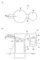
- FIG. 3 schematically shows the evaporative fuel processing apparatus
- FIGS. 3A and 3B are a plan view and a side view, respectively.
- the evaporated fuel processing device 31 includes a liquid level detection valve 32 and a fuel cutoff valve 33.
- the liquid level detection valve 32 has a first float valve body 35 that closes the canister communication hole 34 that is a valve seat when the fuel is full.
- Reference numeral L1 (FIG. 4) indicates the liquid level when the tank is full.
- the fuel cutoff valve 33 includes a second float valve body 37 that closes the evaporation hole 36 that is a valve seat when the vehicle body is largely inclined and the liquid level reaches a predetermined position higher than the full liquid level L1, for example.
- the evaporation hole 36 is located above the canister communication hole 34.
- the first float valve body 35 and the second float valve body 37 are accommodated in a housing 38 attached to the fuel tank T as a valve box.
- the housing 38 is formed with an outlet port 39 connected to a canister (not shown).
- the canister communication hole 34 and the evaporation hole 36 communicate with each other through a communication path 40.
- the evaporative fuel processing device 31 has a structure in which the fuel cutoff valve 33, the liquid level detection valve 32, and the outlet port 39 are laid out in a straight line in this order from one end side.
- the vehicle body is inclined when the vehicle is parked on a slope, for example.
- the liquid level (indicated by symbol L2) is inclined with respect to the housing 38 as shown in FIG. 4B, the canister communication hole 34 and the outlet port 39, which are valve seats, are located below the liquid level L2. The event of being located easily occurs. At this time, if the valve closing function of the first float valve body 35 in the canister communication hole 34 is hindered, liquid fuel may ooze out of the canister communication hole 34 and leak from the outlet port 39.
- the position of the evaporation hole 36 is lowered than the position of the canister communication hole 34, (2) the position of the outlet port 39 is increased, and the like.
- the method (1) is substantially difficult due to the structure of the fuel cutoff valve 33 that functions at a liquid level higher than the full liquid level.
- the method (2) leads to an increase in the height of the housing 38, and the problem of leakage from the canister communication hole 34 still remains. Therefore, the leaked fuel flows to the outlet port 39 due to shaking of the vehicle body or the like. There is a risk of splashing and leaking.
- the present invention was created to solve such a problem, and an object of the present invention is to reduce fuel leakage in an evaporative fuel treatment apparatus for a fuel tank.
- the present invention detects a full tank liquid level during refueling, and closes the first valve seat, and when the liquid level becomes higher than the full liquid level
- An evaporative fuel processing apparatus having a fuel shut-off valve for closing a second valve seat and an outlet port leading to a canister, wherein the second valve seat upper portion and the first valve seat upper portion are communicated in plan view.
- the first communication passage and the second communication passage communicating the upper portion of the first valve seat and the outlet port are formed in a folded shape with the upper portion of the first valve seat as a boundary.
- the first communication path and the second communication path are formed in a folded shape with the upper part of the first valve seat as a boundary, so that the liquid level detection valve, the fuel cutoff valve, and the outlet port from one end side. They are located in order, or in the order of the liquid level detection valve, the outlet port, and the combustion cutoff valve. With this positional relationship, even if the first valve seat is submerged, the outlet port can be laid out so that the liquid is not submerged, and fuel leakage from the outlet port can be reduced.
- first communication passage and the second communication passage are formed in a folded shape with the upper portion of the first valve seat as a boundary, there is a problem in the valve closing function of the second valve seat, and the second valve seat Even when liquid fuel leaks from the tank, the liquid can be dropped to the upper part of the first valve seat in the middle, and liquid leakage from the outlet port can be prevented.
- the present invention is characterized in that a narrow bypass flow path is provided that communicates the second valve seat upper portion and the second communication passage without passing through the first valve seat upper portion.
- the evaporated fuel in the upper part of the second valve seat can escape from the outlet port through the bypass channel.
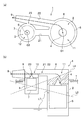
- an evaporated fuel processing apparatus 1 includes a liquid level detection valve 2, a fuel cutoff valve 3, and a housing 8 as a valve box.
- the liquid level detection valve 2 has a first float valve body 5 that detects a full liquid level during refueling and closes the canister communication hole 4 that is a first valve seat. Specifically, when the level of the fuel rises to a predetermined height during refueling, an opening (not shown) of the housing 8 is blocked by the fuel, so that the flow path to the outside of the tank is cut off, and the inside of the fuel tank T The pressure increases. As a result, the fuel rises in the housing 8 and the first float valve body 5 closes the canister communication hole 4.
- the fuel cutoff valve 3 includes a second float valve body 7 that closes the evaporation hole 6 that is the second valve seat when the vehicle body is largely tilted and the liquid level reaches a predetermined position higher than the liquid level L1 when the tank is full.
- the evaporation hole 6 is located above the canister communication hole 4.
- the housing 8 is formed with an outlet port 9 connected to a canister (not shown).
- the outlet port 9 is located above the canister communication hole 4.
- a first valve seat upper portion 11 is defined above the canister communication hole 4
- a second valve seat upper portion 12 is defined above the evaporation hole 6. .
- the first communication passage 21 that communicates the second valve seat upper portion 12 and the first valve seat upper portion 11, and the second communication passage that communicates the first valve seat upper portion 11 and the outlet port 9 22 is formed in a folded shape with the first valve seat upper portion 11 as a boundary.
- the “folded shape” means a line segment (in this embodiment, the extending direction of the first communication path 21) connecting the axis O 1 of the liquid level detection valve 2 and the axis O 2 of the fuel cutoff valve 3 and the second communication path.
- the crossing angle ⁇ with the extending direction 22 is zero (that is, when the first communication path 21 and the second communication path 22 are parallel to each other) or an acute angle.
- the evaporated fuel processing apparatus 1 of the present embodiment includes a narrow bypass passage 23 that communicates the second valve seat upper portion 12 and the second communication passage 22 without passing through the first valve seat upper portion 11.
- “Narrow” means that the flow passage cross-sectional area of the bypass flow passage 23 is smaller than the flow passage cross-sectional areas of the first communication passage 21 and the second communication passage 22.
- the bypass passage 23 is formed as, for example, an extremely small orifice hole, and allows the vaporized fuel to flow from the second valve seat upper portion 12 to the second communication passage 22 but has a function of blocking the passage of liquid fuel.
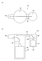
- the outlet port 9 approaches the liquid level (the liquid level at that time is indicated by L3).
- the canister communication hole 4 and the evaporation hole 6 are closed, respectively.
- the canister communication hole 4 as well as the evaporation hole 6 are positioned above the liquid level L3, so that the problem of liquid immersion of the canister communication hole 4 does not occur.
- the intersection of the liquid level L3 and the liquid level L4 is the valve closing liquid level of the fuel cutoff valve 3.
- the canister communication hole 4 and the evaporation hole 6 are respectively formed in the liquid level detection valve 2 and the fuel cutoff valve 3. Closed. In this state, since the canister communication hole 4 is formed below the evaporation hole 6, the canister communication hole 4 is submerged. Conventionally, as shown in FIG. 4, since the outlet port 39 is located further away from the fuel level detection valve 32 than the fuel shutoff valve 33, the canister communication hole 34 is liquidated by the liquid level L2. When submerged, there is a problem that even if the outlet port 39 is formed at a position higher than the canister communication hole 34, the outlet port 39 is liable to be submerged.
- the first communication passage 21 and the second communication passage 22 are formed in a folded shape with the first valve seat upper portion 11 as a boundary.
- the detection valve 2, the fuel cutoff valve 3, and the outlet port 9 are arranged in this order, or the liquid level detection valve 2, the outlet port 9, and the combustion cutoff valve 3 are arranged in this order. That is, the outlet port 9 is located on the opposite side of the liquid level detection valve 2 with the fuel cutoff valve 3 interposed therebetween, or is located closer to the fuel cutoff valve 3 than the liquid level detection valve 2.
- FIG. 2B even if the canister communication hole 4 is submerged in the liquid surface L4, the outlet port 9 can be laid out so as not to be submerged in the liquid surface L4. Fuel leakage can be reduced.
- first communication passage 21 and the second communication passage 22 are formed in a folded shape with the first valve seat upper portion 11 as a boundary, the following effects are also exhibited. If a problem occurs in the valve closing function of the second float valve element 7 in the evaporation hole 6, liquid fuel may leak from the evaporation hole 6.
- the formation position of the evaporation hole 6 is higher than that of the canister communication hole 4 and may be close to the height position of the outlet port 9, so that the second valve seat upper part 12 and the outlet port 9 are connected to the upper part of the first valve seat.
- first communication passage 21 and the second communication passage 22 in a folded shape with the first valve seat upper portion 11 as a boundary, the liquid fuel leaked from the evaporation hole 6 can be removed from the first valve seat upper portion.
- the liquid can be dropped to the portion 11, and the leakage to the folded second communication path 22 can be reduced to prevent liquid leakage from the outlet port 9.
- the 1st valve seat since the narrow bypass flow path 23 which connects the 2nd valve seat upper part 12 and the 2nd communicating path 22 without passing the 1st valve seat upper part 11 is provided, the 1st valve seat temporarily Even when the upper portion 11 is completely submerged and the first communication passage 21 and the second communication passage 22 are not in communication, the evaporated fuel in the second valve seat upper portion 12 passes through the bypass passage 23. It can escape from the exit port 9.
Landscapes
- Engineering & Computer Science (AREA)
- Chemical & Material Sciences (AREA)
- Combustion & Propulsion (AREA)
- Mechanical Engineering (AREA)
- General Engineering & Computer Science (AREA)
- Sustainable Development (AREA)
- Life Sciences & Earth Sciences (AREA)
- Sustainable Energy (AREA)
- Transportation (AREA)
- Cooling, Air Intake And Gas Exhaust, And Fuel Tank Arrangements In Propulsion Units (AREA)
- Supplying Secondary Fuel Or The Like To Fuel, Air Or Fuel-Air Mixtures (AREA)
- Self-Closing Valves And Venting Or Aerating Valves (AREA)
- Float Valves (AREA)
Priority Applications (3)
| Application Number | Priority Date | Filing Date | Title |
|---|---|---|---|
| US14/904,980 US9995259B2 (en) | 2013-11-01 | 2014-09-26 | Evaporated fuel processing device |
| KR1020167004087A KR101868709B1 (ko) | 2013-11-01 | 2014-09-26 | 증발 연료 처리 장치 |
| CN201480038727.7A CN105683555B (zh) | 2013-11-01 | 2014-09-26 | 蒸发燃料处理装置 |
Applications Claiming Priority (2)
| Application Number | Priority Date | Filing Date | Title |
|---|---|---|---|
| JP2013228204A JP6153850B2 (ja) | 2013-11-01 | 2013-11-01 | 蒸発燃料処理装置 |
| JP2013-228204 | 2013-11-01 |
Publications (1)
| Publication Number | Publication Date |
|---|---|
| WO2015064253A1 true WO2015064253A1 (ja) | 2015-05-07 |
Family
ID=53003866
Family Applications (1)
| Application Number | Title | Priority Date | Filing Date |
|---|---|---|---|
| PCT/JP2014/075577 Ceased WO2015064253A1 (ja) | 2013-11-01 | 2014-09-26 | 蒸発燃料処理装置 |
Country Status (5)
| Country | Link |
|---|---|
| US (1) | US9995259B2 (enExample) |
| JP (1) | JP6153850B2 (enExample) |
| KR (1) | KR101868709B1 (enExample) |
| CN (1) | CN105683555B (enExample) |
| WO (1) | WO2015064253A1 (enExample) |
Families Citing this family (2)
| Publication number | Priority date | Publication date | Assignee | Title |
|---|---|---|---|---|
| KR200483760Y1 (ko) | 2017-01-10 | 2017-06-20 | 김성하 | 의자형 때밀이 장치 |
| KR200483980Y1 (ko) | 2017-01-19 | 2017-07-18 | 김성하 | 벽걸이형 때밀이 장치 |
Citations (6)
| Publication number | Priority date | Publication date | Assignee | Title |
|---|---|---|---|---|
| JPS6426535U (enExample) * | 1987-08-10 | 1989-02-15 | ||
| JPH0972258A (ja) * | 1995-09-05 | 1997-03-18 | Nissan Motor Co Ltd | 自動車用燃料タンクのベーパ排出装置 |
| JP2000054918A (ja) * | 1998-08-07 | 2000-02-22 | Mikuni Adec Corp | 蒸散燃料処理装置 |
| JP2001206082A (ja) * | 2000-01-24 | 2001-07-31 | Toyota Motor Corp | 燃料タンクの蒸発ガス抑制装置 |
| JP2010265858A (ja) * | 2009-05-18 | 2010-11-25 | Aisan Ind Co Ltd | 蒸発燃料処理装置 |
| JP2011185239A (ja) * | 2010-03-11 | 2011-09-22 | Honda Motor Co Ltd | 蒸発燃料処理装置 |
Family Cites Families (30)
| Publication number | Priority date | Publication date | Assignee | Title |
|---|---|---|---|---|
| JPS5652088Y2 (enExample) * | 1975-05-29 | 1981-12-04 | ||
| JPS5357116U (enExample) * | 1976-10-19 | 1978-05-16 | ||
| JPH051645Y2 (enExample) * | 1987-02-02 | 1993-01-18 | ||
| US4782084A (en) | 1987-06-29 | 1988-11-01 | Merck & Co., Inc. | HMG-COA reductase inhibitors |
| JPH0250169U (enExample) * | 1988-09-30 | 1990-04-09 | ||
| JP2514397Y2 (ja) * | 1989-01-31 | 1996-10-16 | 株式会社土屋製作所 | 燃料タンクのフィラ―チュ―ブ |
| JP2616599B2 (ja) * | 1991-05-31 | 1997-06-04 | 日産自動車株式会社 | 燃料タンクの蒸発燃料処理装置 |
| JPH07132740A (ja) * | 1993-11-05 | 1995-05-23 | Toyoda Gosei Co Ltd | 燃料蒸気処理装置 |
| JP3515648B2 (ja) * | 1995-10-13 | 2004-04-05 | 本田技研工業株式会社 | 蒸発燃料処理装置 |
| US5687756A (en) * | 1995-11-08 | 1997-11-18 | Borg-Warner Automotive, Inc. | Vehicle refueling valve |
| JP3777214B2 (ja) * | 1996-01-08 | 2006-05-24 | 株式会社ニフコ | 燃料流出防止弁装置 |
| JPH10205634A (ja) * | 1997-01-17 | 1998-08-04 | Nok Corp | 液体遮断弁装置 |
| JP3902694B2 (ja) * | 1997-08-29 | 2007-04-11 | 富士重工業株式会社 | 燃料蒸気排出防止装置 |
| JP3914320B2 (ja) * | 1998-01-26 | 2007-05-16 | 株式会社ミクニ | 燃料遮断装置及びその燃料遮断装置の連結構造 |
| JP2000097120A (ja) * | 1998-09-16 | 2000-04-04 | Nifco Inc | 燃料タンク装置 |
| BE1012390A3 (fr) * | 1999-01-18 | 2000-10-03 | Solvay | Systeme de mise a l'air de reservoir a liquide. |
| BE1012697A3 (fr) * | 1999-06-01 | 2001-02-06 | Solvay | Reservoir a carburant. |
| JP4231174B2 (ja) * | 1999-11-12 | 2009-02-25 | 京三電機株式会社 | 燃料蒸発ガス制御装置 |
| JP2001182633A (ja) * | 1999-12-27 | 2001-07-06 | Kyosan Denki Kk | 燃料蒸発ガス処理装置 |
| JP2002004966A (ja) * | 2000-06-26 | 2002-01-09 | Kyosan Denki Co Ltd | 燃料蒸発ガス処理装置 |
| JP2002285929A (ja) * | 2001-03-26 | 2002-10-03 | Nifco Inc | 過給油防止バルブ |
| JP3911185B2 (ja) * | 2002-04-05 | 2007-05-09 | 株式会社ニフコ | 過給油防止バルブ |
| JP4070229B2 (ja) * | 2002-08-08 | 2008-04-02 | 本田技研工業株式会社 | 蒸発燃料処理装置 |
| JP4318937B2 (ja) * | 2003-03-12 | 2009-08-26 | 本田技研工業株式会社 | 蒸発燃料処理装置 |
| US6810862B2 (en) * | 2003-03-27 | 2004-11-02 | Eaton Corporation | Fuel tank vapor relief valve and method of making same |
| US7207347B2 (en) * | 2004-08-23 | 2007-04-24 | Raval A.S.C. Ltd. | Dual function valve for fuel tank |
| JP4534841B2 (ja) * | 2004-08-30 | 2010-09-01 | 豊田合成株式会社 | 燃料遮断弁 |
| JP4881659B2 (ja) * | 2006-06-16 | 2012-02-22 | 株式会社パイオラックス | 液体遮断弁装置 |
| JP2011161974A (ja) * | 2010-02-05 | 2011-08-25 | Toyota Motor Corp | 燃料タンク、並びに同燃料タンクを具備する蒸発燃料処理装置 |
| JP5795179B2 (ja) * | 2011-04-07 | 2015-10-14 | 本田技研工業株式会社 | 車両の蒸発燃料処理装置 |
-
2013
- 2013-11-01 JP JP2013228204A patent/JP6153850B2/ja active Active
-
2014
- 2014-09-26 WO PCT/JP2014/075577 patent/WO2015064253A1/ja not_active Ceased
- 2014-09-26 KR KR1020167004087A patent/KR101868709B1/ko active Active
- 2014-09-26 CN CN201480038727.7A patent/CN105683555B/zh active Active
- 2014-09-26 US US14/904,980 patent/US9995259B2/en active Active
Patent Citations (6)
| Publication number | Priority date | Publication date | Assignee | Title |
|---|---|---|---|---|
| JPS6426535U (enExample) * | 1987-08-10 | 1989-02-15 | ||
| JPH0972258A (ja) * | 1995-09-05 | 1997-03-18 | Nissan Motor Co Ltd | 自動車用燃料タンクのベーパ排出装置 |
| JP2000054918A (ja) * | 1998-08-07 | 2000-02-22 | Mikuni Adec Corp | 蒸散燃料処理装置 |
| JP2001206082A (ja) * | 2000-01-24 | 2001-07-31 | Toyota Motor Corp | 燃料タンクの蒸発ガス抑制装置 |
| JP2010265858A (ja) * | 2009-05-18 | 2010-11-25 | Aisan Ind Co Ltd | 蒸発燃料処理装置 |
| JP2011185239A (ja) * | 2010-03-11 | 2011-09-22 | Honda Motor Co Ltd | 蒸発燃料処理装置 |
Also Published As
| Publication number | Publication date |
|---|---|
| CN105683555B (zh) | 2018-09-14 |
| US20160153410A1 (en) | 2016-06-02 |
| KR20160042425A (ko) | 2016-04-19 |
| KR101868709B1 (ko) | 2018-06-18 |
| JP2015086835A (ja) | 2015-05-07 |
| CN105683555A (zh) | 2016-06-15 |
| US9995259B2 (en) | 2018-06-12 |
| JP6153850B2 (ja) | 2017-06-28 |
Similar Documents
| Publication | Publication Date | Title |
|---|---|---|
| US8910652B2 (en) | Fuel ventilation system valve | |
| KR100959222B1 (ko) | 연료 탱크 장치 | |
| US20070289633A1 (en) | On-Board refueling vapor recovery system with vent line check valve | |
| DE102007052396A1 (de) | Elektrisch gesteuerte Abschaltung der Dampfentlüftung beim Betanken | |
| CN107531146B (zh) | 鞍形燃料箱中的电子排气 | |
| JP6838270B2 (ja) | 燃料タンクの開閉装置 | |
| JP6153850B2 (ja) | 蒸発燃料処理装置 | |
| JP6791975B2 (ja) | インレット逆止弁を有する燃料タンク | |
| US10259314B2 (en) | Fuel tank system | |
| EP1433646B1 (en) | Fuel vapor processing apparatus | |
| JP2015086835A5 (enExample) | ||
| US12090837B2 (en) | Over-fueling prevention valve | |
| JP5937851B2 (ja) | 気液分離装置 | |
| JP6319547B2 (ja) | 車両の燃料タンク装置 | |
| JP6341373B2 (ja) | 車両用液体タンク | |
| US20120298211A1 (en) | Liquid trap for fuel vapor valve | |
| JP6159356B2 (ja) | 燃料供給装置 | |
| JP2006160114A (ja) | 燃料タンク装置 | |
| KR20070005033A (ko) | 증발가스 방지를 위한 연료 주입 장치 | |
| JPH08158972A (ja) | フューエルタンク装置 | |
| JP2005036730A (ja) | 燃料供給装置 | |
| JPH06278481A (ja) | 車両用燃料タンク装置 |
Legal Events
| Date | Code | Title | Description |
|---|---|---|---|
| 121 | Ep: the epo has been informed by wipo that ep was designated in this application |
Ref document number: 14859000 Country of ref document: EP Kind code of ref document: A1 |
|
| WWE | Wipo information: entry into national phase |
Ref document number: 14904980 Country of ref document: US |
|
| ENP | Entry into the national phase |
Ref document number: 20167004087 Country of ref document: KR Kind code of ref document: A |
|
| NENP | Non-entry into the national phase |
Ref country code: DE |
|
| 122 | Ep: pct application non-entry in european phase |
Ref document number: 14859000 Country of ref document: EP Kind code of ref document: A1 |