WO2015059893A1 - Soufflante centrifuge - Google Patents
Soufflante centrifuge Download PDFInfo
- Publication number
- WO2015059893A1 WO2015059893A1 PCT/JP2014/005196 JP2014005196W WO2015059893A1 WO 2015059893 A1 WO2015059893 A1 WO 2015059893A1 JP 2014005196 W JP2014005196 W JP 2014005196W WO 2015059893 A1 WO2015059893 A1 WO 2015059893A1
- Authority
- WO
- WIPO (PCT)
- Prior art keywords
- fan
- protrusion
- case
- side plate
- centrifugal
- Prior art date
Links
Images


Classifications
-
- B—PERFORMING OPERATIONS; TRANSPORTING
- B60—VEHICLES IN GENERAL
- B60N—SEATS SPECIALLY ADAPTED FOR VEHICLES; VEHICLE PASSENGER ACCOMMODATION NOT OTHERWISE PROVIDED FOR
- B60N2/00—Seats specially adapted for vehicles; Arrangement or mounting of seats in vehicles
- B60N2/56—Heating or ventilating devices
- B60N2/5607—Heating or ventilating devices characterised by convection
- B60N2/5621—Heating or ventilating devices characterised by convection by air
- B60N2/565—Heating or ventilating devices characterised by convection by air sucked from the seat surface
-
- F—MECHANICAL ENGINEERING; LIGHTING; HEATING; WEAPONS; BLASTING
- F04—POSITIVE - DISPLACEMENT MACHINES FOR LIQUIDS; PUMPS FOR LIQUIDS OR ELASTIC FLUIDS
- F04D—NON-POSITIVE-DISPLACEMENT PUMPS
- F04D25/00—Pumping installations or systems
- F04D25/02—Units comprising pumps and their driving means
- F04D25/06—Units comprising pumps and their driving means the pump being electrically driven
- F04D25/0606—Units comprising pumps and their driving means the pump being electrically driven the electric motor being specially adapted for integration in the pump
- F04D25/0613—Units comprising pumps and their driving means the pump being electrically driven the electric motor being specially adapted for integration in the pump the electric motor being of the inside-out type, i.e. the rotor is arranged radially outside a central stator
-
- F—MECHANICAL ENGINEERING; LIGHTING; HEATING; WEAPONS; BLASTING
- F04—POSITIVE - DISPLACEMENT MACHINES FOR LIQUIDS; PUMPS FOR LIQUIDS OR ELASTIC FLUIDS
- F04D—NON-POSITIVE-DISPLACEMENT PUMPS
- F04D29/00—Details, component parts, or accessories
- F04D29/02—Selection of particular materials
- F04D29/023—Selection of particular materials especially adapted for elastic fluid pumps
-
- F—MECHANICAL ENGINEERING; LIGHTING; HEATING; WEAPONS; BLASTING
- F04—POSITIVE - DISPLACEMENT MACHINES FOR LIQUIDS; PUMPS FOR LIQUIDS OR ELASTIC FLUIDS
- F04D—NON-POSITIVE-DISPLACEMENT PUMPS
- F04D29/00—Details, component parts, or accessories
- F04D29/08—Sealings
- F04D29/16—Sealings between pressure and suction sides
- F04D29/161—Sealings between pressure and suction sides especially adapted for elastic fluid pumps
- F04D29/162—Sealings between pressure and suction sides especially adapted for elastic fluid pumps of a centrifugal flow wheel
-
- F—MECHANICAL ENGINEERING; LIGHTING; HEATING; WEAPONS; BLASTING
- F04—POSITIVE - DISPLACEMENT MACHINES FOR LIQUIDS; PUMPS FOR LIQUIDS OR ELASTIC FLUIDS
- F04D—NON-POSITIVE-DISPLACEMENT PUMPS
- F04D29/00—Details, component parts, or accessories
- F04D29/26—Rotors specially for elastic fluids
- F04D29/28—Rotors specially for elastic fluids for centrifugal or helico-centrifugal pumps for radial-flow or helico-centrifugal pumps
- F04D29/281—Rotors specially for elastic fluids for centrifugal or helico-centrifugal pumps for radial-flow or helico-centrifugal pumps for fans or blowers
-
- F—MECHANICAL ENGINEERING; LIGHTING; HEATING; WEAPONS; BLASTING
- F04—POSITIVE - DISPLACEMENT MACHINES FOR LIQUIDS; PUMPS FOR LIQUIDS OR ELASTIC FLUIDS
- F04D—NON-POSITIVE-DISPLACEMENT PUMPS
- F04D29/00—Details, component parts, or accessories
- F04D29/40—Casings; Connections of working fluid
- F04D29/42—Casings; Connections of working fluid for radial or helico-centrifugal pumps
- F04D29/4206—Casings; Connections of working fluid for radial or helico-centrifugal pumps especially adapted for elastic fluid pumps
- F04D29/4226—Fan casings
Definitions
- This disclosure relates to a centrifugal blower.
- centrifugal fan that includes a centrifugal fan that blows air sucked in from the axial direction of a rotating shaft in a radial direction, and a case that accommodates the centrifugal fan and is formed with an air inlet and outlet.
- the centrifugal fan is rotated inside the case. Therefore, in order to suppress sliding resistance between the centrifugal fan and the case, the centrifugal fan and the case are generally arranged so as not to contact each other. ing.
- the fan efficiency ⁇ f is a ratio of theoretical air power to rotational driving force (shaft power) necessary for rotating the centrifugal fan.
- the theoretical aerodynamic power is indicated by a value corresponding to the work output from the centrifugal blower.
- the centrifugal blower disclosed in Patent Document 1 a protrusion (bellows) that protrudes toward the centrifugal fan side is formed in the suction port that opens in the case, and between the bellows and the upper surface side plate of the centrifugal fan.
- the gap is almost zero.
- the upper surface side plate is a plate-like member arranged so as to face the suction side surface of the centrifugal fan where the suction port of the case is formed.
- the present disclosure aims to achieve both suppression of the backflow of air blown out from the centrifugal fan toward the suction port side and suppression of increase in axial power of the centrifugal fan.
- the centrifugal fan according to the first aspect of the present disclosure is rotated by being transmitted with a rotational driving force, and houses a centrifugal fan that blows air sucked in from the axial direction of the rotating shaft in a radial direction, and a centrifugal fan, A case in which an air inlet is formed.
- the centrifugal fan has a plurality of blades arranged in an annular shape around the axis of the rotation shaft, and an upper surface side arranged to face a suction side surface in which a plurality of blades are fixed and a suction port is formed in the case Has a plate.
- a seal material made of a semi-solid substance is disposed in a gap between the suction side surface and the upper surface side plate. The sealing material is in contact with both the suction side surface and the upper surface side plate, and is arranged in an annular shape around the axis of the rotation shaft when viewed from the axial direction.
- the sealing material is disposed in the gap between the suction side surface of the case and the upper surface side plate of the centrifugal fan, and is further disposed in an annular shape so that the sealing material contacts both the suction side surface and the upper surface side plate. Therefore, it is possible to prevent the air blown out from the centrifugal fan from flowing backward to the suction port side through the gap between the suction side surface and the upper surface side plate.
- the centrifugal fan and the case are not in direct contact, the sliding resistance between the centrifugal fan and the case can be suppressed. Therefore, it can suppress that the axial power of a centrifugal fan will increase.
- centrifugal blower that enables both suppression of backflow of air blown out from the centrifugal fan to the suction port side and suppression of increase in axial power of the centrifugal fan. it can.
- the centrifugal fan according to the second aspect of the present disclosure accommodates a centrifugal fan that rotates by being transmitted with a rotational driving force and blows out the air sucked in from the axial direction of the rotating shaft in a radial direction, and the centrifugal fan, And a case in which an air inlet is formed.
- the centrifugal fan has a plurality of blades arranged in an annular shape around the axis of the rotation shaft, and an upper surface side arranged to face a suction side surface in which a plurality of blades are fixed and a suction port is formed in the case Has a plate.
- the suction side surface has a case-side protruding portion that is formed in an annular shape when viewed from the axial direction and protrudes toward the upper surface side plate.
- the upper surface side plate has a fan side protruding portion that is formed in an annular shape and protrudes toward the suction side surface when viewed from the axial direction.
- the case side protrusion and the fan side protrusion at least one protrusion is provided in plural.
- a sealing material made of a semi-solid substance is disposed between the one protrusions.
- the tip of the other protrusion is in contact with the sealing material.
- the cross-sectional shape in the axial cross section of the tip portion is formed into a shape that gradually tapers in the protruding direction.
- a sealing material is disposed between one of the protrusions. Furthermore, the tip of the other protrusion is in contact with the sealing material. Therefore, it is possible to prevent the air blown out from the centrifugal fan from flowing back to the suction port side through the gap between the suction side surface of the case and the upper surface side plate of the centrifugal fan.
- the other protrusion since a sealing material made of a semi-solid material is used, when the other protrusion is formed, the dimension in the protruding direction of the other protrusion is slightly different from the target dimension. In addition, the tip of the other protrusion can be easily brought into contact with the sealing material. Therefore, when forming the other protrusion, it can be easily formed without requiring a high degree of tolerance management.
- the centrifugal fan and the case are not in direct contact, the sliding resistance between the centrifugal fan and the case can be suppressed.
- the cross-sectional shape in the axial cross section of the tip is formed so as to gradually taper in the protruding direction. Therefore, it is possible to reduce the contact area between the tip portion and the sealing material and suppress an increase in sliding resistance between the tip portion and the sealing material. Therefore, it can suppress that the axial power of a centrifugal fan will increase.
- the centrifugal fan according to the third aspect of the present disclosure is rotated by being transmitted with a rotational driving force, and houses a centrifugal fan that blows air sucked in from the axial direction of the rotating shaft in a radial direction, and a centrifugal fan, And a case in which an air inlet is formed.
- the centrifugal fan has a plurality of blades arranged in an annular shape around the axis of the rotation shaft, and an upper surface side arranged to face a suction side surface in which a plurality of blades are fixed and a suction port is formed in the case Has a plate.
- the suction side surface has a case-side protruding portion that is formed in an annular shape when viewed from the axial direction and protrudes toward the upper surface side plate.
- the upper surface side plate has a fan side protruding portion that is formed in an annular shape and protrudes toward the suction side surface when viewed from the axial direction.
- the case side protrusion and the fan side protrusion constitute a labyrinth seal in a gap formed between the suction side surface and the upper surface side plate.
- the size of the gap between the suction side surface and the upper surface side plate on the inner peripheral side of the labyrinth seal is larger than the size of the gap between the suction side surface and the upper surface side plate on the outer peripheral side of the labyrinth seal. It is getting smaller.
- the case side protrusion and the fan side protrusion form a labyrinth seal in a gap formed between the suction side surface and the upper surface side plate. Further, the dimension of the gap on the inner peripheral side (rotating shaft side) of the labyrinth seal is smaller than the dimension of the gap on the outer peripheral side.
- centrifugal fan and the case are not in direct contact. Therefore, sliding resistance between the centrifugal fan and the case can be suppressed.
- the inner peripheral side (rotating shaft side) of the centrifugal fan is less displaced by vibration or the like than the outer peripheral side, the parts forming the inner peripheral side of the labyrinth seal in the centrifugal fan and the case come into contact with each other and slide. It is also possible to suppress an increase in dynamic resistance. Therefore, it can suppress that the axial power of a centrifugal fan will increase.
- centrifugal blower that enables both suppression of backflow of air blown out from the centrifugal fan to the suction port side and suppression of increase in axial power of the centrifugal fan. it can.
- FIG. 4 is a sectional view taken along line IV-IV in FIG. 2. It is a graph which shows the change of the fan efficiency with respect to the change of the flow coefficient of the centrifugal blower of 1st Embodiment. It is a graph which shows the change of the specific noise with respect to the change of the fan efficiency of an air blower.
- Centrifugal blower 10 of this embodiment is applied to a seat air conditioner for vehicles, and inhales the air in a vehicle interior in a seat air conditioner.
- a centrifugal blower 10 is accommodated in a seat S on which an occupant is seated.
- the centrifugal blower 10 is operated to suck air near the surface of the seat S through the pores provided in the seat S, thereby reducing the temperature and humidity near the surface of the seat S to reduce the passenger The feeling of cooling is improved.
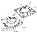
- the centrifugal blower 10 of the present embodiment includes a centrifugal fan 20 and a case 30.
- the centrifugal fan 20 blows out the air sucked from the axial direction of the rotating shaft in the radial direction.
- the case 30 accommodates the centrifugal fan 20 and has a suction port 30a for sucking air into the inside and a blower outlet 30b for blowing air to the outside.
- the case 30 is made of resin and has an upper case 31 and a lower case 32.
- the upper case 31 has a circular inlet 30a at the center.
- the lower case 32 has a flat rectangular shape, and a main body portion of an electric motor described later is fixed to the lower case 32. More specifically, as shown in the exploded perspective view of FIG. 3, the corners of the upper case 31 and the lower case 32 are fixed by bolting or the like.
- the suction port 30a formed in the upper case 31 is arranged coaxially with the rotating shaft of the centrifugal fan 20. Further, as shown in FIG. 2, a plurality of air outlets 30 b are formed on the side surface of the case 30 by gaps between the upper case 31 and the lower case 32. Since this blower outlet 30b is formed between each corner
- the centrifugal fan 20 is made of resin and has a plurality of blades 21, an upper surface side plate 22, and a lower surface side plate 23.
- the plurality of blades 21 are arranged in an annular shape around the axis of the rotation shaft.
- the upper surface side plate 22 has a substantially flat plate shape formed in an annular shape when viewed from the axial direction of the rotation shaft.
- the lower surface side plate 23 has a substantially conical shape.
- the centrifugal fan 20 of the present embodiment is configured as a backward-facing fan (turbo fan). Further, the plurality of blades 21 are sandwiched and fixed between the both sides in the axial direction of the rotation shaft and the outer peripheral sides of the conical side surfaces of the upper surface side plate 22 and the lower surface side plate 23.
- the upper surface side plate 22 is disposed so as to face the suction side surface 31a in which the suction port 30a of the upper case 31 is formed.
- a circular fan side suction hole 20 a through which air sucked through the suction port 30 a of the upper case 31 flows into the centrifugal fan 20 is formed at the center of the upper surface side plate 22.
- the fan-side suction hole 20 a is disposed coaxially with the rotation shaft, and forms the innermost peripheral portion of the upper surface side plate 22.
- An electric motor (not shown) is disposed on the inner peripheral side of the conical side surface of the lower surface side plate 23, and the rotating shaft of the electric motor is connected to the lower surface side plate 23.
- the main body of the electric motor is fixed to the lower case 32. Therefore, when the rotational driving force is transmitted from the electric motor to the centrifugal fan 20 (specifically, the lower surface side plate 23), the centrifugal fan 20 rotates in the case 30.
- a gap is formed between the centrifugal fan 20 and the case 30 so that the centrifugal fan 20 and the case 30 do not directly contact when the centrifugal fan 20 rotates. Thereby, the sliding resistance between the centrifugal fan 20 and the case 30 is suppressed.
- the operation of the electric motor is controlled by a control voltage output from a control device (not shown).
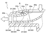
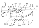
- case-side protruding portions 31b that protrude in the axial direction of the rotating shaft toward the upper surface side plate 22 of the centrifugal fan 20. Is formed. These two case-side protruding portions 31b are formed to have dimensions that do not contact the top surface side plate 22 with the tip portions 22b.
- these two case-side protruding portions 31b are formed in an annular shape having different diameters when viewed from the axial direction of the rotating shaft, and are arranged coaxially with the rotating shaft. Moreover, between the radial directions of the two case side protrusions 31b, grease G as a sealing material made of a semi-solid substance is filled over the entire circumference. More specifically, in this embodiment, the grease G has a viscosity of about 0.024 Pa ⁇ S and a kinematic viscosity of about 26 cSt.
- the upper surface side plate 22 of the centrifugal fan 20 is formed with one fan side protruding portion 22a that protrudes in the axial direction of the rotating shaft toward the suction side surface 31a of the upper case 31.
- the fan-side protrusion 22a is also formed in an annular shape when viewed from the axial direction of the rotating shaft, and is arranged coaxially with the rotating shaft.
- the diameter of the fan-side protruding portion 22a is formed to be larger than the diameter of the case-side protruding portion 31b on the inner peripheral side and smaller than the diameter of the case-side protruding portion 31b on the outer peripheral side.
- tip part 22b of the fan side protrusion part 22a protrudes between two case side protrusion parts 31b, and is filled between two case side protrusion parts 31b, without contacting the suction
- the grease G is in contact with the entire circumference.
- the tip 22b of the fan-side protruding portion 22a is formed in a shape in which the cross-sectional shape in the axial section gradually tapers in the protruding direction.
- the cross-sectional shape in the cross section in the axial direction is a cross-sectional shape in a cross section including the rotation axis. More specifically, the cross-sectional shape in the axial cross section of the tip end portion 22b of the present embodiment is formed in an acutely sharp shape.
- the case side protruding portion 31b constitutes one protruding portion
- the fan side protruding portion 22a constitutes the other protruding portion.
- the case-side protrusion 31 b and the fan-side protrusion 22 a are located closer to the innermost peripheral part (fan-side suction hole 20 a) than the outermost peripheral part of the centrifugal fan 20. Yes.
- the centrifugal blower 10 of the present embodiment the centrifugal fan 20 rotates when the control device operates the electric motor. Thereby, the air near the surface of the sheet S is sucked from the suction port 30a of the case 30 and blown out from the blower outlet 30b.
- the centrifugal blower 10 according to the present embodiment operates as described above, and sucks air in the vehicle compartment in the seat air conditioner.
- the centrifugal fan is rotated inside the case. Therefore, the fan efficiency ⁇ f can be improved by suppressing the sliding resistance between the centrifugal fan and the case and reducing the rotational driving force (shaft power) required for rotating the centrifugal fan. Therefore, like the centrifugal blower 10 of the present embodiment, the centrifugal fan is disposed so as not to contact the case.
- the fan efficiency ⁇ f may decrease instead.
- the grease G is filled between the two case side protrusions 31b, and the tip 22b of the fan side protrusion 22a is in contact with the grease G. .
- the air blown out from the centrifugal fan 20 from flowing backward to the suction port 30a through the gap between the suction side surface 31a of the case 30 and the upper surface side plate 22 of the centrifugal fan 20.
- the air pressure (discharge pressure) on the outlet side is higher than the air pressure (suction pressure) on the inlet side of the centrifugal fan 20. Prone. As a result, the air blown out from the centrifugal fan 20 tends to flow backward toward the suction port 30a. Therefore, in a centrifugal fan provided with a rearward fan, the ability to prevent backflow as in this embodiment is extremely effective for improving fan efficiency ⁇ f.
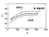
- the shaft power of the centrifugal fan 20 is It has been found that if backflow can be prevented without increasing the fan efficiency, the fan efficiency ⁇ f can be improved by about 15%, as shown by the change from the broken line to the alternate long and short dash line in FIG.
- the centrifugal blower in which the grease G is not filled between the two case-side protruding portions 31b is a centrifugal blower as a comparative example in which a backflow can occur.
- the centrifugal blower as the comparative example is referred to as a comparative blower. In the comparative blower, a back flow is generated, but no sliding resistance is generated between the centrifugal fan 20 and the grease G.
- the centrifugal fan 20 and the case 30 are not in direct contact. Therefore, sliding resistance between the centrifugal fan 20 and the case 30 can be suppressed.
- the cross-sectional shape in the axial cross section of the tip end portion 22b of the fan-side protruding portion 22a is formed into a shape that gradually tapers in the protruding direction. Therefore, the contact area between the fan-side protrusion 22a and the grease S can be reduced, and an increase in the sliding resistance between the fan-side protrusion 22a and the grease G can be suppressed.
- the area of the tip 22b of the fan-side protrusion 22a that is in contact with the grease G is A, and the relative speed between the fan-side protrusion 22a and the grease G when the centrifugal fan 20 rotates.
- U U
- the load F received by the fan-side protruding portion 22a can be obtained from the following formula F1.
- the load F corresponds to the sliding resistance between the fan-side protruding portion 22a and the grease G.
- the centrifugal blower 10 of the present embodiment can prevent backflow with an increase in shaft power of about 10% compared to the above-described comparative blower.
- the centrifugal blower 10 of the present embodiment the air blown from the centrifugal fan 20 is prevented from flowing back to the suction port 30a side of the case 30, and the axial power of the centrifugal fan 20 is increased. Can be achieved at the same time.
- the fan efficiency ⁇ f can be improved by about 5% with respect to the comparative blower, as shown by the solid line in FIG.
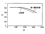
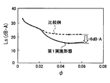
- a general blower can reduce the specific noise Ls of the blower by improving the fan efficiency ⁇ f as shown in FIG. Therefore, also in the centrifugal blower 10 of the present embodiment, the specific noise LS can be reduced by the effect of improving the fan efficiency ⁇ f described above.
- the pressure coefficient ⁇ with respect to the flow coefficient ⁇ is improved by the above-described effect of improving the fan efficiency ⁇ f, as shown by the solid line in FIG. Can be made.
- a desired operating point air volume and pressure
- the specific noise Ls at a desired operating point can be reduced as compared with the comparative blower indicated by the broken line.
- the flow rate coefficient ⁇ and the pressure coefficient ⁇ used in FIGS. 5 to 8 are the air volume (flow rate) of the air blown from the blower and the blower in order to compare the performance of the two fans under the same operating conditions. This is a value obtained by making the air pressure blown from the air non-dimensional.
- the same operating condition is, for example, a condition in which two fans are formed to have the same fan diameter and are operated at the same rotational speed.
- grease G made of a semi-solid substance is employed as a sealing material. Therefore, when the fan-side protrusion 22a is formed, even if the dimension in the protrusion direction of the fan-side protrusion 22a is slightly different from the target dimension, by adjusting the filling amount of the grease G, the fan-side protrusion The tip 22b of the portion 22a can be easily brought into contact with the grease G. That is, when forming the fan-side protruding portion 22a, it can be easily formed without requiring sophisticated tolerance management.
- the centrifugal blower 10 of the present embodiment a plurality of case side protrusions 31b are provided, and the grease G is filled between the case side protrusions 31b. Therefore, unlike the case where a plurality of fan-side protrusions 22a are provided and the grease G is filled between the fan-side protrusions 22a, the weight of the centrifugal fan 20 is not increased and the shaft power is not increased. Further, the grease G is not peeled off by the centrifugal force generated when the centrifugal fan 20 rotates.
- the case-side protruding portion 31b and the fan-side protruding portion 22a are positioned closer to the innermost peripheral portion (fan-side suction hole 20a) than the outermost peripheral portion of the upper surface side plate 22. is doing. Therefore, the contact area between the fan-side protruding portion 22a and the grease G can be reduced as compared with the case where the position is close to the outermost peripheral portion. Therefore, it is possible to effectively suppress an increase in the sliding resistance between the fan-side protruding portion 22a and the grease G.
- the fan-side protruding portion 22a is positioned on the outer peripheral side of the innermost peripheral portion (fan-side suction hole 20a) of the upper surface side plate 22. Therefore, the shape of the fan-side protrusion 22a can be reliably and easily formed in an annular shape that fits the case-side protrusion 31b without being affected by the shape of the fan-side suction hole 20a.
- FIG. 9 is a drawing corresponding to FIG. 4 of the first embodiment, and the same or equivalent parts as in the first embodiment are denoted by the same reference numerals. This also applies to FIGS. 10 to 12 below.
- case side protrusions 31b and fan side protrusions 22a are provided (three in this embodiment). As shown in the axial cross section of FIG. 9, the diameters of the case-side protrusions 31b and the diameters of the fan-side protrusions 22a are alternately increased. That is, the case side protrusions 31b and the fan side protrusions 22a are alternately arranged in the radial direction when viewed from the axial direction of the rotating shaft.
- the case-side protrusions 31b and the fan-side protrusions 22a of the present embodiment are arranged by alternately disposing the case-side protrusions 31b and the fan-side protrusions 22a facing each other in the radial direction. Constitutes a labyrinth seal structure in a gap space formed between the suction side surface 31 a of the case 30 and the upper surface side plate 22 of the centrifugal fan 20.
- the dimension ⁇ in of the gap between the suction side 31a on the inner peripheral side of the labyrinth seal structure and the upper surface side plate 22 is the same as the suction side 31a on the outer peripheral side of the labyrinth seal. It is smaller than the dimension ⁇ out of the gap with the upper surface side plate 22.
- Other configurations and operations of the centrifugal fan 10 are the same as those in the first embodiment.
- the plurality of case-side protrusions 31b and the plurality of fan-side protrusions 22a are in a labyrinth seal within a gap formed between the suction side surface 31a and the upper surface side plate 22. Is configured. Furthermore, the clearance dimension ⁇ in on the inner peripheral side (rotating shaft side) of the labyrinth seal is smaller than the clearance dimension ⁇ out on the outer peripheral side.
- the centrifugal blower 10 of this embodiment since the centrifugal fan 20 and the case 30 are not in direct contact, the sliding resistance between the centrifugal fan 20 and the case 30 can be suppressed. At this time, the amount of displacement due to vibration or the like is smaller on the inner peripheral side (rotating shaft side) of the centrifugal fan 20 than on the outer peripheral side. Therefore, it can also be suppressed that the portions forming the inner peripheral side of the labyrinth seal in the centrifugal fan 20 and the case 30 come into contact with each other and increase the sliding resistance.
- the air blown out from the centrifugal fan 20 is prevented from flowing back to the suction port 30a side of the case 30, and the axial power of the centrifugal fan 20 is increased. It is possible to achieve both suppression.
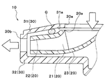
- a modification of the first embodiment will be described. In the centrifugal blower 10 of this embodiment, as shown in FIG. 10, the fan side protrusion 22a and the case side protrusion 31b are abolished with respect to the first embodiment.
- the grease G of the present embodiment is disposed in a gap between the suction side surface 31 a of the case 30 and the upper surface side plate 22 of the centrifugal fan 20. Furthermore, the grease G is in contact with both the suction side surface 31a and the upper surface side plate 22, and is arranged in an annular shape around the axis of the rotation shaft when viewed from the axial direction. Other configurations are the same as those of the first embodiment.
- the grease G is in contact with both the suction side surface 31 a and the upper surface side plate 22” means that the grease G is in contact with a portion of the suction side surface 31 a and the upper surface side plate 22 that is formed in a planar shape. It is not limited to the meaning of doing.
- the suction side surface 31a or the upper surface side plate 22 has a protrusion or a recess, it means that the grease G is in contact with the inside of the tip or the recess of the protrusion.
- the grease G as the sealing material is disposed in the gap between the suction side surface 31a and the upper surface side plate 22. Therefore, similarly to the first embodiment, it is possible to prevent the air blown out from the centrifugal fan 20 from flowing back to the suction port 30a side through the gap between the suction side surface 31a and the upper surface side plate 22.
- the fan side protruding portion 22a and the case side protruding portion 31b are abolished. Therefore, the above-described backflow prevention effect can be obtained with a very simple configuration in which the grease G is disposed in the gap between the suction side surface 31a and the upper surface side plate 22.
- the centrifugal blower 10 of the present embodiment since the centrifugal force acts on the grease G as the centrifugal fan 20 rotates, the grease G easily moves to the outer peripheral side. Therefore, it is desirable that the centrifugal blower 10 of the present embodiment be used as a centrifugal blower that rotates the centrifugal fan 20 at a lower rotational speed range than the first embodiment.
- the centrifugal blower 10 of the present embodiment in order to suppress the peeling of the sealing material, it is desirable to shorten the gap distance between the suction side surface 31a and the upper surface side plate 22 as compared with the first embodiment. .
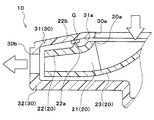
- a modification of the first embodiment will be described.
- the case side protrusion part 31b is abolished with respect to 1st Embodiment.
- the front end portion 22 b of the fan-side protrusion 22 a of the upper surface side plate 22 is in contact with the grease G disposed in the gap between the suction side surface 31 a and the upper surface side plate 22.
- Other configurations are the same as those of the first embodiment.
- the recess 31c is formed in an annular shape around the axis of the rotating shaft when viewed from the axial direction of the rotating shaft, and is recessed on the side away from the fan-side protruding portion 22a.
- the fan-side protrusion 22a and the recess 31c are arranged so as to overlap each other when viewed from the axial direction.
- the fan-side protrusion 22a protrudes so that the tip 22b reaches the inside of the recess 31c.
- the grease G of this embodiment is filled in the inside of the recess 31c over the entire circumference. And the front-end
- Other configurations are the same as those of the first embodiment.
- the centrifugal blower 10 of this embodiment when the centrifugal blower 10 of this embodiment is operated, the air in the vehicle compartment can be sucked in the seat air conditioner, as in the first embodiment. Further, the air blown out from the centrifugal fan 20 can be prevented from flowing back to the suction port 30a through the gap between the suction side surface 31a and the upper surface side plate 22, and the same as in the first embodiment. An effect can be obtained. (Other embodiments)
- the present disclosure is not limited to the above-described embodiment, and can be variously modified as follows without departing from the spirit of the present disclosure.
- case side protrusions 31b and the number of fan side protrusions 22a are not limited to the numbers described in the first embodiment, and a plurality of both case side protrusions 31b and fan side protrusions 22a are provided. Also good.
- the example in which the case-side protruding portion 31b is eliminated has been described, but the fan-side protruding portion 22a may be eliminated.
- one case-side protruding portion 31b is formed, and the cross-sectional shape in the axial section of the tip portion of the case-side protruding portion 31b is gradually tapered toward the protruding direction. Also good.
- the case side protruding portion 31b is eliminated and the concave portion 31c is formed in the case 30 has been described.
- the fan-side protruding portion 22a may be eliminated and a similar recess may be formed in the upper surface side plate 22.
- one case-side protruding portion 31b may be formed, and the tip of the case-side protruding portion 31b may be brought into contact with the grease G disposed in the recess formed in the upper surface side plate 22. .
- the cross-sectional shape in the axial section of the tip of the fan-side protruding portion 22a is an acutely sharp shape
- the cross-sectional shape of the front end portion of the fan-side protruding portion 22a is not limited to this.
- the cross-sectional shape may be formed in a semicircular shape, or may be formed in a semielliptical shape.
- the cross-sectional shape of the case-side protrusion 31b in the axial section is similarly directed in the protrusion direction.
- the shape may be gradually tapered.
- the sealing material is not limited thereto.
- a magnetic fluid or the like may be adopted as long as it is a substance having both liquid properties and solid properties and having a predetermined viscosity and kinematic viscosity.
- the case side protruding portion 31b is arranged to protrude vertically downward.
- the grease G does not fall from between the case-side protruding portions 31b.
- the centrifugal fan 20 and the case 30 of the centrifugal blower 10 are formed of resin.
- the centrifugal fan 20 and the case 30 may be formed of polypropylene.
- the constituent members of the centrifugal fan 20 and the case 30 are not limited as long as the functions of the constituent members can be exhibited. Therefore, you may form these structural members with a metal etc.
- the centrifugal fan 20 may be a forward-facing fan (sirocco fan) in which a plurality of blades are formed in a shape inclined in the rotational direction from the radially inner side to the outer side.
- centrifugal blower 10 according to the present disclosure is applied to a vehicle seat air conditioner has been described.
- the application of the centrifugal blower 10 is not limited thereto.
- the present invention may be applied to a cooling fan or a vacuum cleaner for a CPU of a personal computer.
Abstract
Selon l'invention, deux saillies côté carter (31b), formées sous une forme annulaire, vues à partir de la direction axiale et faisant saillie vers un ventilateur centrifuge (20), sont disposées sur une surface côté aspiration (31a) d'un carter (30) logeant le ventilateur centrifuge (20), la surface côté aspiration (31a) ayant un orifice d'aspiration (30a) formé sur celle-ci. Une saillie côté ventilateur (22a), formée sous une forme annulaire, vue à partir de la direction axiale et faisant saillie vers la surface côté aspiration (31a), est disposée sur une plaque de face supérieure (22) du ventilateur centrifuge (20), la plaque de face supérieure (22) étant disposée de façon à faire face à la surface côté aspiration (31a). De plus, un espace radial entre les deux saillies côté carter (31b) est rempli de graisse (G). La pointe de la saillie côté ventilateur (22a), formée sous une forme s'effilant graduellement dans la direction de saillie, est amenée en contact avec la graisse (G).
Priority Applications (1)
| Application Number | Priority Date | Filing Date | Title |
|---|---|---|---|
| US15/030,329 US20160264028A1 (en) | 2013-10-21 | 2014-10-14 | Centrifugal blower |
Applications Claiming Priority (4)
| Application Number | Priority Date | Filing Date | Title |
|---|---|---|---|
| JP2013218367 | 2013-10-21 | ||
| JP2013-218367 | 2013-10-21 | ||
| JP2014145611A JP6260481B2 (ja) | 2013-10-21 | 2014-07-16 | 遠心送風機 |
| JP2014-145611 | 2014-07-16 |
Publications (1)
| Publication Number | Publication Date |
|---|---|
| WO2015059893A1 true WO2015059893A1 (fr) | 2015-04-30 |
Family
ID=52992513
Family Applications (1)
| Application Number | Title | Priority Date | Filing Date |
|---|---|---|---|
| PCT/JP2014/005196 WO2015059893A1 (fr) | 2013-10-21 | 2014-10-14 | Soufflante centrifuge |
Country Status (3)
| Country | Link |
|---|---|
| US (1) | US20160264028A1 (fr) |
| JP (1) | JP6260481B2 (fr) |
| WO (1) | WO2015059893A1 (fr) |
Cited By (2)
| Publication number | Priority date | Publication date | Assignee | Title |
|---|---|---|---|---|
| CN109404339A (zh) * | 2018-12-18 | 2019-03-01 | 南京磁谷科技有限公司 | 一种用于高速电直驱离心式风机的蜗壳组件 |
| EP3489519A4 (fr) * | 2016-07-21 | 2020-03-18 | LG Innotek Co., Ltd. | Moteur de ventilateur et véhicule le comprenant |
Families Citing this family (17)
| Publication number | Priority date | Publication date | Assignee | Title |
|---|---|---|---|---|
| JP6076945B2 (ja) * | 2014-07-25 | 2017-02-08 | ミネベア株式会社 | 遠心式ファン |
| CN105275873A (zh) * | 2015-10-27 | 2016-01-27 | 上海华鼓鼓风机有限公司 | 一种用于低速运行鼓风机的三元流闭式铸造叶轮 |
| JP6352232B2 (ja) * | 2015-11-02 | 2018-07-04 | ミネベアミツミ株式会社 | 遠心ファン |
| JP6717029B2 (ja) * | 2015-11-09 | 2020-07-01 | 日本電産株式会社 | 送風装置、および清掃機器 |
| WO2017145780A1 (fr) * | 2016-02-24 | 2017-08-31 | 株式会社デンソー | Ventilateur centrifuge |
| JP2018155188A (ja) * | 2017-03-17 | 2018-10-04 | ミネベアミツミ株式会社 | 遠心ファン |
| WO2018180063A1 (fr) | 2017-03-29 | 2018-10-04 | 株式会社デンソー | Soufflante centrifuge |
| JP6766800B2 (ja) * | 2017-03-29 | 2020-10-14 | 株式会社デンソー | 遠心送風機 |
| DE112017007402T5 (de) * | 2017-04-07 | 2019-12-19 | Pierburg Pump Technology Gmbh | Kraftfahrzeug-Gasförderpumpe |
| JP7081910B2 (ja) * | 2017-08-08 | 2022-06-07 | 日立グローバルライフソリューションズ株式会社 | 電動送風機およびそれを搭載した電気掃除機 |
| CN108730201A (zh) * | 2018-04-24 | 2018-11-02 | 中山市博匠泵业有限公司 | 双吸液下泵 |
| JP6620841B2 (ja) * | 2018-06-06 | 2019-12-18 | ミネベアミツミ株式会社 | 遠心ファン |
| JP7168441B2 (ja) * | 2018-12-25 | 2022-11-09 | 三菱重工業株式会社 | 遠心回転機械 |
| KR20210132505A (ko) * | 2020-04-27 | 2021-11-04 | 삼성전자주식회사 | 모터 어셈블리 및 이를 포함하는 청소기 |
| GB2596547A (en) * | 2020-06-30 | 2022-01-05 | Dyson Technology Ltd | Seal for a compressor |
| US11746798B2 (en) * | 2020-11-24 | 2023-09-05 | Delta Electronics, Inc. | Centrifugal fan |
| TWM629128U (zh) * | 2022-03-07 | 2022-07-01 | 高昌生醫股份有限公司 | 鼓風機 |
Citations (7)
| Publication number | Priority date | Publication date | Assignee | Title |
|---|---|---|---|---|
| CH138087A (de) * | 1929-02-19 | 1930-02-15 | Escher Wyss Maschf Ag | Dichtung an sich drehenden Maschinenteilen, insbesondere von Kreiselmaschinen. |
| JPS5440311A (en) * | 1977-09-07 | 1979-03-29 | Hitachi Ltd | Seal structure for centrifugal compressor etc. |
| JPH1113688A (ja) * | 1997-06-23 | 1999-01-19 | Hitachi Ltd | ラビリンスシール装置及びそれを備えた流体機械 |
| JPH11190295A (ja) * | 1997-12-25 | 1999-07-13 | Hitachi Ltd | 電動送風機および該電動送風機を用いた電気掃除機 |
| JPH11190296A (ja) * | 1997-12-25 | 1999-07-13 | Hitachi Ltd | 電動送風機 |
| JP2012154278A (ja) * | 2011-01-27 | 2012-08-16 | Minebea Co Ltd | 遠心式ファン |
| WO2014041223A1 (fr) * | 2012-09-12 | 2014-03-20 | Soler & Palau Research, S.L. | Couplage entre une roue centrifuge et sa bouche d'aspiration |
Family Cites Families (6)
| Publication number | Priority date | Publication date | Assignee | Title |
|---|---|---|---|---|
| US2869471A (en) * | 1957-02-01 | 1959-01-20 | Robert D Copeland | Impeller pump, seal and wear ring |
| US4061279A (en) * | 1976-03-01 | 1977-12-06 | Pennsylvania Crusher Corporation | High-speed rotating crushing machinery |
| JP4865497B2 (ja) * | 2006-10-19 | 2012-02-01 | 三菱重工業株式会社 | 遠心式送風装置 |
| JP5645596B2 (ja) * | 2010-10-25 | 2014-12-24 | 三菱重工業株式会社 | 多翼遠心ファンおよびそれを用いた空気調和機 |
| EP2546526B1 (fr) * | 2011-07-14 | 2016-08-17 | Black & Decker Inc. | Agencement de turbine |
| KR101960714B1 (ko) * | 2012-11-30 | 2019-03-22 | 한화파워시스템 주식회사 | 임펠러 |
-
2014
- 2014-07-16 JP JP2014145611A patent/JP6260481B2/ja not_active Expired - Fee Related
- 2014-10-14 US US15/030,329 patent/US20160264028A1/en not_active Abandoned
- 2014-10-14 WO PCT/JP2014/005196 patent/WO2015059893A1/fr active Application Filing
Patent Citations (7)
| Publication number | Priority date | Publication date | Assignee | Title |
|---|---|---|---|---|
| CH138087A (de) * | 1929-02-19 | 1930-02-15 | Escher Wyss Maschf Ag | Dichtung an sich drehenden Maschinenteilen, insbesondere von Kreiselmaschinen. |
| JPS5440311A (en) * | 1977-09-07 | 1979-03-29 | Hitachi Ltd | Seal structure for centrifugal compressor etc. |
| JPH1113688A (ja) * | 1997-06-23 | 1999-01-19 | Hitachi Ltd | ラビリンスシール装置及びそれを備えた流体機械 |
| JPH11190295A (ja) * | 1997-12-25 | 1999-07-13 | Hitachi Ltd | 電動送風機および該電動送風機を用いた電気掃除機 |
| JPH11190296A (ja) * | 1997-12-25 | 1999-07-13 | Hitachi Ltd | 電動送風機 |
| JP2012154278A (ja) * | 2011-01-27 | 2012-08-16 | Minebea Co Ltd | 遠心式ファン |
| WO2014041223A1 (fr) * | 2012-09-12 | 2014-03-20 | Soler & Palau Research, S.L. | Couplage entre une roue centrifuge et sa bouche d'aspiration |
Cited By (4)
| Publication number | Priority date | Publication date | Assignee | Title |
|---|---|---|---|---|
| EP3489519A4 (fr) * | 2016-07-21 | 2020-03-18 | LG Innotek Co., Ltd. | Moteur de ventilateur et véhicule le comprenant |
| US10897169B2 (en) | 2016-07-21 | 2021-01-19 | Lg Innotek Co., Ltd. | Fan motor and vehicle comprising same |
| CN109404339A (zh) * | 2018-12-18 | 2019-03-01 | 南京磁谷科技有限公司 | 一种用于高速电直驱离心式风机的蜗壳组件 |
| CN109404339B (zh) * | 2018-12-18 | 2023-09-22 | 南京磁谷科技有限公司 | 一种用于高速电直驱离心式风机的蜗壳组件 |
Also Published As
| Publication number | Publication date |
|---|---|
| JP6260481B2 (ja) | 2018-01-17 |
| JP2015108369A (ja) | 2015-06-11 |
| US20160264028A1 (en) | 2016-09-15 |
Similar Documents
| Publication | Publication Date | Title |
|---|---|---|
| WO2015059893A1 (fr) | Soufflante centrifuge | |
| JP4631941B2 (ja) | 遠心式送風機 | |
| US7329100B2 (en) | Centrifugal fan impeller | |
| EP1845603A2 (fr) | Moteur à ventilation axiale | |
| US9745984B2 (en) | Fan and pressure-increasing blade assembly thereof | |
| US20070231145A1 (en) | Multiple Fans of Cascade Connection | |
| JP2013060839A (ja) | 電動送風機 | |
| EP1840384A2 (fr) | Ventilateur centrifuge | |
| AU2011272257B2 (en) | Blower device | |
| WO2010113391A1 (fr) | Soufflante centrifuge et siège d'automobile | |
| CN101725562A (zh) | 散热风扇及其叶轮 | |
| US20190390676A1 (en) | Centrifugal blower device | |
| US20190264696A1 (en) | Centrifugal fan | |
| JP6844526B2 (ja) | 多翼遠心ファン | |
| US10962017B2 (en) | Centrifugal fan | |
| JPS62265498A (ja) | 特に自動車の空調装置用の半径流フアン | |
| US7932654B2 (en) | Motor | |
| WO2015059869A1 (fr) | Ventilateur centrifuge | |
| CN107882774B (zh) | 可逆转风扇 | |
| JP2010029259A (ja) | 電気掃除機 | |
| US11300134B2 (en) | Blower | |
| JP2006125229A (ja) | シロッコファン | |
| JP2009036049A (ja) | 遠心ファンモータ | |
| US10557476B2 (en) | Mixed-flow fan | |
| KR101781694B1 (ko) | 원심팬 |
Legal Events
| Date | Code | Title | Description |
|---|---|---|---|
| 121 | Ep: the epo has been informed by wipo that ep was designated in this application |
Ref document number: 14856673 Country of ref document: EP Kind code of ref document: A1 |
|
| WWE | Wipo information: entry into national phase |
Ref document number: 15030329 Country of ref document: US |
|
| NENP | Non-entry into the national phase |
Ref country code: DE |
|
| 122 | Ep: pct application non-entry in european phase |
Ref document number: 14856673 Country of ref document: EP Kind code of ref document: A1 |