WO2015059893A1 - Centrifugal blower - Google Patents
Centrifugal blower Download PDFInfo
- Publication number
- WO2015059893A1 WO2015059893A1 PCT/JP2014/005196 JP2014005196W WO2015059893A1 WO 2015059893 A1 WO2015059893 A1 WO 2015059893A1 JP 2014005196 W JP2014005196 W JP 2014005196W WO 2015059893 A1 WO2015059893 A1 WO 2015059893A1
- Authority
- WO
- WIPO (PCT)
- Prior art keywords
- fan
- protrusion
- case
- side plate
- centrifugal
- Prior art date
Links
Images


Classifications
-
- B—PERFORMING OPERATIONS; TRANSPORTING
- B60—VEHICLES IN GENERAL
- B60N—SEATS SPECIALLY ADAPTED FOR VEHICLES; VEHICLE PASSENGER ACCOMMODATION NOT OTHERWISE PROVIDED FOR
- B60N2/00—Seats specially adapted for vehicles; Arrangement or mounting of seats in vehicles
- B60N2/56—Heating or ventilating devices
- B60N2/5607—Heating or ventilating devices characterised by convection
- B60N2/5621—Heating or ventilating devices characterised by convection by air
- B60N2/565—Heating or ventilating devices characterised by convection by air sucked from the seat surface
-
- F—MECHANICAL ENGINEERING; LIGHTING; HEATING; WEAPONS; BLASTING
- F04—POSITIVE - DISPLACEMENT MACHINES FOR LIQUIDS; PUMPS FOR LIQUIDS OR ELASTIC FLUIDS
- F04D—NON-POSITIVE-DISPLACEMENT PUMPS
- F04D25/00—Pumping installations or systems
- F04D25/02—Units comprising pumps and their driving means
- F04D25/06—Units comprising pumps and their driving means the pump being electrically driven
- F04D25/0606—Units comprising pumps and their driving means the pump being electrically driven the electric motor being specially adapted for integration in the pump
- F04D25/0613—Units comprising pumps and their driving means the pump being electrically driven the electric motor being specially adapted for integration in the pump the electric motor being of the inside-out type, i.e. the rotor is arranged radially outside a central stator
-
- F—MECHANICAL ENGINEERING; LIGHTING; HEATING; WEAPONS; BLASTING
- F04—POSITIVE - DISPLACEMENT MACHINES FOR LIQUIDS; PUMPS FOR LIQUIDS OR ELASTIC FLUIDS
- F04D—NON-POSITIVE-DISPLACEMENT PUMPS
- F04D29/00—Details, component parts, or accessories
- F04D29/02—Selection of particular materials
- F04D29/023—Selection of particular materials especially adapted for elastic fluid pumps
-
- F—MECHANICAL ENGINEERING; LIGHTING; HEATING; WEAPONS; BLASTING
- F04—POSITIVE - DISPLACEMENT MACHINES FOR LIQUIDS; PUMPS FOR LIQUIDS OR ELASTIC FLUIDS
- F04D—NON-POSITIVE-DISPLACEMENT PUMPS
- F04D29/00—Details, component parts, or accessories
- F04D29/08—Sealings
- F04D29/16—Sealings between pressure and suction sides
- F04D29/161—Sealings between pressure and suction sides especially adapted for elastic fluid pumps
- F04D29/162—Sealings between pressure and suction sides especially adapted for elastic fluid pumps of a centrifugal flow wheel
-
- F—MECHANICAL ENGINEERING; LIGHTING; HEATING; WEAPONS; BLASTING
- F04—POSITIVE - DISPLACEMENT MACHINES FOR LIQUIDS; PUMPS FOR LIQUIDS OR ELASTIC FLUIDS
- F04D—NON-POSITIVE-DISPLACEMENT PUMPS
- F04D29/00—Details, component parts, or accessories
- F04D29/26—Rotors specially for elastic fluids
- F04D29/28—Rotors specially for elastic fluids for centrifugal or helico-centrifugal pumps for radial-flow or helico-centrifugal pumps
- F04D29/281—Rotors specially for elastic fluids for centrifugal or helico-centrifugal pumps for radial-flow or helico-centrifugal pumps for fans or blowers
-
- F—MECHANICAL ENGINEERING; LIGHTING; HEATING; WEAPONS; BLASTING
- F04—POSITIVE - DISPLACEMENT MACHINES FOR LIQUIDS; PUMPS FOR LIQUIDS OR ELASTIC FLUIDS
- F04D—NON-POSITIVE-DISPLACEMENT PUMPS
- F04D29/00—Details, component parts, or accessories
- F04D29/40—Casings; Connections of working fluid
- F04D29/42—Casings; Connections of working fluid for radial or helico-centrifugal pumps
- F04D29/4206—Casings; Connections of working fluid for radial or helico-centrifugal pumps especially adapted for elastic fluid pumps
- F04D29/4226—Fan casings
Definitions
- This disclosure relates to a centrifugal blower.
- centrifugal fan that includes a centrifugal fan that blows air sucked in from the axial direction of a rotating shaft in a radial direction, and a case that accommodates the centrifugal fan and is formed with an air inlet and outlet.
- the centrifugal fan is rotated inside the case. Therefore, in order to suppress sliding resistance between the centrifugal fan and the case, the centrifugal fan and the case are generally arranged so as not to contact each other. ing.
- the fan efficiency ⁇ f is a ratio of theoretical air power to rotational driving force (shaft power) necessary for rotating the centrifugal fan.
- the theoretical aerodynamic power is indicated by a value corresponding to the work output from the centrifugal blower.
- the centrifugal blower disclosed in Patent Document 1 a protrusion (bellows) that protrudes toward the centrifugal fan side is formed in the suction port that opens in the case, and between the bellows and the upper surface side plate of the centrifugal fan.
- the gap is almost zero.
- the upper surface side plate is a plate-like member arranged so as to face the suction side surface of the centrifugal fan where the suction port of the case is formed.
- the present disclosure aims to achieve both suppression of the backflow of air blown out from the centrifugal fan toward the suction port side and suppression of increase in axial power of the centrifugal fan.
- the centrifugal fan according to the first aspect of the present disclosure is rotated by being transmitted with a rotational driving force, and houses a centrifugal fan that blows air sucked in from the axial direction of the rotating shaft in a radial direction, and a centrifugal fan, A case in which an air inlet is formed.
- the centrifugal fan has a plurality of blades arranged in an annular shape around the axis of the rotation shaft, and an upper surface side arranged to face a suction side surface in which a plurality of blades are fixed and a suction port is formed in the case Has a plate.
- a seal material made of a semi-solid substance is disposed in a gap between the suction side surface and the upper surface side plate. The sealing material is in contact with both the suction side surface and the upper surface side plate, and is arranged in an annular shape around the axis of the rotation shaft when viewed from the axial direction.
- the sealing material is disposed in the gap between the suction side surface of the case and the upper surface side plate of the centrifugal fan, and is further disposed in an annular shape so that the sealing material contacts both the suction side surface and the upper surface side plate. Therefore, it is possible to prevent the air blown out from the centrifugal fan from flowing backward to the suction port side through the gap between the suction side surface and the upper surface side plate.
- the centrifugal fan and the case are not in direct contact, the sliding resistance between the centrifugal fan and the case can be suppressed. Therefore, it can suppress that the axial power of a centrifugal fan will increase.
- centrifugal blower that enables both suppression of backflow of air blown out from the centrifugal fan to the suction port side and suppression of increase in axial power of the centrifugal fan. it can.
- the centrifugal fan according to the second aspect of the present disclosure accommodates a centrifugal fan that rotates by being transmitted with a rotational driving force and blows out the air sucked in from the axial direction of the rotating shaft in a radial direction, and the centrifugal fan, And a case in which an air inlet is formed.
- the centrifugal fan has a plurality of blades arranged in an annular shape around the axis of the rotation shaft, and an upper surface side arranged to face a suction side surface in which a plurality of blades are fixed and a suction port is formed in the case Has a plate.
- the suction side surface has a case-side protruding portion that is formed in an annular shape when viewed from the axial direction and protrudes toward the upper surface side plate.
- the upper surface side plate has a fan side protruding portion that is formed in an annular shape and protrudes toward the suction side surface when viewed from the axial direction.
- the case side protrusion and the fan side protrusion at least one protrusion is provided in plural.
- a sealing material made of a semi-solid substance is disposed between the one protrusions.
- the tip of the other protrusion is in contact with the sealing material.
- the cross-sectional shape in the axial cross section of the tip portion is formed into a shape that gradually tapers in the protruding direction.
- a sealing material is disposed between one of the protrusions. Furthermore, the tip of the other protrusion is in contact with the sealing material. Therefore, it is possible to prevent the air blown out from the centrifugal fan from flowing back to the suction port side through the gap between the suction side surface of the case and the upper surface side plate of the centrifugal fan.
- the other protrusion since a sealing material made of a semi-solid material is used, when the other protrusion is formed, the dimension in the protruding direction of the other protrusion is slightly different from the target dimension. In addition, the tip of the other protrusion can be easily brought into contact with the sealing material. Therefore, when forming the other protrusion, it can be easily formed without requiring a high degree of tolerance management.
- the centrifugal fan and the case are not in direct contact, the sliding resistance between the centrifugal fan and the case can be suppressed.
- the cross-sectional shape in the axial cross section of the tip is formed so as to gradually taper in the protruding direction. Therefore, it is possible to reduce the contact area between the tip portion and the sealing material and suppress an increase in sliding resistance between the tip portion and the sealing material. Therefore, it can suppress that the axial power of a centrifugal fan will increase.
- the centrifugal fan according to the third aspect of the present disclosure is rotated by being transmitted with a rotational driving force, and houses a centrifugal fan that blows air sucked in from the axial direction of the rotating shaft in a radial direction, and a centrifugal fan, And a case in which an air inlet is formed.
- the centrifugal fan has a plurality of blades arranged in an annular shape around the axis of the rotation shaft, and an upper surface side arranged to face a suction side surface in which a plurality of blades are fixed and a suction port is formed in the case Has a plate.
- the suction side surface has a case-side protruding portion that is formed in an annular shape when viewed from the axial direction and protrudes toward the upper surface side plate.
- the upper surface side plate has a fan side protruding portion that is formed in an annular shape and protrudes toward the suction side surface when viewed from the axial direction.
- the case side protrusion and the fan side protrusion constitute a labyrinth seal in a gap formed between the suction side surface and the upper surface side plate.
- the size of the gap between the suction side surface and the upper surface side plate on the inner peripheral side of the labyrinth seal is larger than the size of the gap between the suction side surface and the upper surface side plate on the outer peripheral side of the labyrinth seal. It is getting smaller.
- the case side protrusion and the fan side protrusion form a labyrinth seal in a gap formed between the suction side surface and the upper surface side plate. Further, the dimension of the gap on the inner peripheral side (rotating shaft side) of the labyrinth seal is smaller than the dimension of the gap on the outer peripheral side.
- centrifugal fan and the case are not in direct contact. Therefore, sliding resistance between the centrifugal fan and the case can be suppressed.
- the inner peripheral side (rotating shaft side) of the centrifugal fan is less displaced by vibration or the like than the outer peripheral side, the parts forming the inner peripheral side of the labyrinth seal in the centrifugal fan and the case come into contact with each other and slide. It is also possible to suppress an increase in dynamic resistance. Therefore, it can suppress that the axial power of a centrifugal fan will increase.
- centrifugal blower that enables both suppression of backflow of air blown out from the centrifugal fan to the suction port side and suppression of increase in axial power of the centrifugal fan. it can.
- FIG. 4 is a sectional view taken along line IV-IV in FIG. 2. It is a graph which shows the change of the fan efficiency with respect to the change of the flow coefficient of the centrifugal blower of 1st Embodiment. It is a graph which shows the change of the specific noise with respect to the change of the fan efficiency of an air blower.
- Centrifugal blower 10 of this embodiment is applied to a seat air conditioner for vehicles, and inhales the air in a vehicle interior in a seat air conditioner.
- a centrifugal blower 10 is accommodated in a seat S on which an occupant is seated.
- the centrifugal blower 10 is operated to suck air near the surface of the seat S through the pores provided in the seat S, thereby reducing the temperature and humidity near the surface of the seat S to reduce the passenger The feeling of cooling is improved.
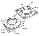
- the centrifugal blower 10 of the present embodiment includes a centrifugal fan 20 and a case 30.
- the centrifugal fan 20 blows out the air sucked from the axial direction of the rotating shaft in the radial direction.
- the case 30 accommodates the centrifugal fan 20 and has a suction port 30a for sucking air into the inside and a blower outlet 30b for blowing air to the outside.
- the case 30 is made of resin and has an upper case 31 and a lower case 32.
- the upper case 31 has a circular inlet 30a at the center.
- the lower case 32 has a flat rectangular shape, and a main body portion of an electric motor described later is fixed to the lower case 32. More specifically, as shown in the exploded perspective view of FIG. 3, the corners of the upper case 31 and the lower case 32 are fixed by bolting or the like.
- the suction port 30a formed in the upper case 31 is arranged coaxially with the rotating shaft of the centrifugal fan 20. Further, as shown in FIG. 2, a plurality of air outlets 30 b are formed on the side surface of the case 30 by gaps between the upper case 31 and the lower case 32. Since this blower outlet 30b is formed between each corner
- the centrifugal fan 20 is made of resin and has a plurality of blades 21, an upper surface side plate 22, and a lower surface side plate 23.
- the plurality of blades 21 are arranged in an annular shape around the axis of the rotation shaft.
- the upper surface side plate 22 has a substantially flat plate shape formed in an annular shape when viewed from the axial direction of the rotation shaft.
- the lower surface side plate 23 has a substantially conical shape.
- the centrifugal fan 20 of the present embodiment is configured as a backward-facing fan (turbo fan). Further, the plurality of blades 21 are sandwiched and fixed between the both sides in the axial direction of the rotation shaft and the outer peripheral sides of the conical side surfaces of the upper surface side plate 22 and the lower surface side plate 23.
- the upper surface side plate 22 is disposed so as to face the suction side surface 31a in which the suction port 30a of the upper case 31 is formed.
- a circular fan side suction hole 20 a through which air sucked through the suction port 30 a of the upper case 31 flows into the centrifugal fan 20 is formed at the center of the upper surface side plate 22.
- the fan-side suction hole 20 a is disposed coaxially with the rotation shaft, and forms the innermost peripheral portion of the upper surface side plate 22.
- An electric motor (not shown) is disposed on the inner peripheral side of the conical side surface of the lower surface side plate 23, and the rotating shaft of the electric motor is connected to the lower surface side plate 23.
- the main body of the electric motor is fixed to the lower case 32. Therefore, when the rotational driving force is transmitted from the electric motor to the centrifugal fan 20 (specifically, the lower surface side plate 23), the centrifugal fan 20 rotates in the case 30.
- a gap is formed between the centrifugal fan 20 and the case 30 so that the centrifugal fan 20 and the case 30 do not directly contact when the centrifugal fan 20 rotates. Thereby, the sliding resistance between the centrifugal fan 20 and the case 30 is suppressed.
- the operation of the electric motor is controlled by a control voltage output from a control device (not shown).
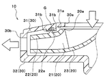
- case-side protruding portions 31b that protrude in the axial direction of the rotating shaft toward the upper surface side plate 22 of the centrifugal fan 20. Is formed. These two case-side protruding portions 31b are formed to have dimensions that do not contact the top surface side plate 22 with the tip portions 22b.
- these two case-side protruding portions 31b are formed in an annular shape having different diameters when viewed from the axial direction of the rotating shaft, and are arranged coaxially with the rotating shaft. Moreover, between the radial directions of the two case side protrusions 31b, grease G as a sealing material made of a semi-solid substance is filled over the entire circumference. More specifically, in this embodiment, the grease G has a viscosity of about 0.024 Pa ⁇ S and a kinematic viscosity of about 26 cSt.
- the upper surface side plate 22 of the centrifugal fan 20 is formed with one fan side protruding portion 22a that protrudes in the axial direction of the rotating shaft toward the suction side surface 31a of the upper case 31.
- the fan-side protrusion 22a is also formed in an annular shape when viewed from the axial direction of the rotating shaft, and is arranged coaxially with the rotating shaft.
- the diameter of the fan-side protruding portion 22a is formed to be larger than the diameter of the case-side protruding portion 31b on the inner peripheral side and smaller than the diameter of the case-side protruding portion 31b on the outer peripheral side.
- tip part 22b of the fan side protrusion part 22a protrudes between two case side protrusion parts 31b, and is filled between two case side protrusion parts 31b, without contacting the suction
- the grease G is in contact with the entire circumference.
- the tip 22b of the fan-side protruding portion 22a is formed in a shape in which the cross-sectional shape in the axial section gradually tapers in the protruding direction.
- the cross-sectional shape in the cross section in the axial direction is a cross-sectional shape in a cross section including the rotation axis. More specifically, the cross-sectional shape in the axial cross section of the tip end portion 22b of the present embodiment is formed in an acutely sharp shape.
- the case side protruding portion 31b constitutes one protruding portion
- the fan side protruding portion 22a constitutes the other protruding portion.
- the case-side protrusion 31 b and the fan-side protrusion 22 a are located closer to the innermost peripheral part (fan-side suction hole 20 a) than the outermost peripheral part of the centrifugal fan 20. Yes.
- the centrifugal blower 10 of the present embodiment the centrifugal fan 20 rotates when the control device operates the electric motor. Thereby, the air near the surface of the sheet S is sucked from the suction port 30a of the case 30 and blown out from the blower outlet 30b.
- the centrifugal blower 10 according to the present embodiment operates as described above, and sucks air in the vehicle compartment in the seat air conditioner.
- the centrifugal fan is rotated inside the case. Therefore, the fan efficiency ⁇ f can be improved by suppressing the sliding resistance between the centrifugal fan and the case and reducing the rotational driving force (shaft power) required for rotating the centrifugal fan. Therefore, like the centrifugal blower 10 of the present embodiment, the centrifugal fan is disposed so as not to contact the case.
- the fan efficiency ⁇ f may decrease instead.
- the grease G is filled between the two case side protrusions 31b, and the tip 22b of the fan side protrusion 22a is in contact with the grease G. .
- the air blown out from the centrifugal fan 20 from flowing backward to the suction port 30a through the gap between the suction side surface 31a of the case 30 and the upper surface side plate 22 of the centrifugal fan 20.
- the air pressure (discharge pressure) on the outlet side is higher than the air pressure (suction pressure) on the inlet side of the centrifugal fan 20. Prone. As a result, the air blown out from the centrifugal fan 20 tends to flow backward toward the suction port 30a. Therefore, in a centrifugal fan provided with a rearward fan, the ability to prevent backflow as in this embodiment is extremely effective for improving fan efficiency ⁇ f.
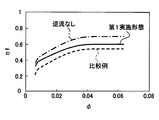
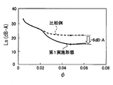
- the shaft power of the centrifugal fan 20 is It has been found that if backflow can be prevented without increasing the fan efficiency, the fan efficiency ⁇ f can be improved by about 15%, as shown by the change from the broken line to the alternate long and short dash line in FIG.
- the centrifugal blower in which the grease G is not filled between the two case-side protruding portions 31b is a centrifugal blower as a comparative example in which a backflow can occur.
- the centrifugal blower as the comparative example is referred to as a comparative blower. In the comparative blower, a back flow is generated, but no sliding resistance is generated between the centrifugal fan 20 and the grease G.
- the centrifugal fan 20 and the case 30 are not in direct contact. Therefore, sliding resistance between the centrifugal fan 20 and the case 30 can be suppressed.
- the cross-sectional shape in the axial cross section of the tip end portion 22b of the fan-side protruding portion 22a is formed into a shape that gradually tapers in the protruding direction. Therefore, the contact area between the fan-side protrusion 22a and the grease S can be reduced, and an increase in the sliding resistance between the fan-side protrusion 22a and the grease G can be suppressed.
- the area of the tip 22b of the fan-side protrusion 22a that is in contact with the grease G is A, and the relative speed between the fan-side protrusion 22a and the grease G when the centrifugal fan 20 rotates.
- U U
- the load F received by the fan-side protruding portion 22a can be obtained from the following formula F1.
- the load F corresponds to the sliding resistance between the fan-side protruding portion 22a and the grease G.
- the centrifugal blower 10 of the present embodiment can prevent backflow with an increase in shaft power of about 10% compared to the above-described comparative blower.
- the centrifugal blower 10 of the present embodiment the air blown from the centrifugal fan 20 is prevented from flowing back to the suction port 30a side of the case 30, and the axial power of the centrifugal fan 20 is increased. Can be achieved at the same time.
- the fan efficiency ⁇ f can be improved by about 5% with respect to the comparative blower, as shown by the solid line in FIG.
- a general blower can reduce the specific noise Ls of the blower by improving the fan efficiency ⁇ f as shown in FIG. Therefore, also in the centrifugal blower 10 of the present embodiment, the specific noise LS can be reduced by the effect of improving the fan efficiency ⁇ f described above.
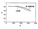
- the pressure coefficient ⁇ with respect to the flow coefficient ⁇ is improved by the above-described effect of improving the fan efficiency ⁇ f, as shown by the solid line in FIG. Can be made.
- a desired operating point air volume and pressure
- the specific noise Ls at a desired operating point can be reduced as compared with the comparative blower indicated by the broken line.
- the flow rate coefficient ⁇ and the pressure coefficient ⁇ used in FIGS. 5 to 8 are the air volume (flow rate) of the air blown from the blower and the blower in order to compare the performance of the two fans under the same operating conditions. This is a value obtained by making the air pressure blown from the air non-dimensional.
- the same operating condition is, for example, a condition in which two fans are formed to have the same fan diameter and are operated at the same rotational speed.
- grease G made of a semi-solid substance is employed as a sealing material. Therefore, when the fan-side protrusion 22a is formed, even if the dimension in the protrusion direction of the fan-side protrusion 22a is slightly different from the target dimension, by adjusting the filling amount of the grease G, the fan-side protrusion The tip 22b of the portion 22a can be easily brought into contact with the grease G. That is, when forming the fan-side protruding portion 22a, it can be easily formed without requiring sophisticated tolerance management.
- the centrifugal blower 10 of the present embodiment a plurality of case side protrusions 31b are provided, and the grease G is filled between the case side protrusions 31b. Therefore, unlike the case where a plurality of fan-side protrusions 22a are provided and the grease G is filled between the fan-side protrusions 22a, the weight of the centrifugal fan 20 is not increased and the shaft power is not increased. Further, the grease G is not peeled off by the centrifugal force generated when the centrifugal fan 20 rotates.
- the case-side protruding portion 31b and the fan-side protruding portion 22a are positioned closer to the innermost peripheral portion (fan-side suction hole 20a) than the outermost peripheral portion of the upper surface side plate 22. is doing. Therefore, the contact area between the fan-side protruding portion 22a and the grease G can be reduced as compared with the case where the position is close to the outermost peripheral portion. Therefore, it is possible to effectively suppress an increase in the sliding resistance between the fan-side protruding portion 22a and the grease G.
- the fan-side protruding portion 22a is positioned on the outer peripheral side of the innermost peripheral portion (fan-side suction hole 20a) of the upper surface side plate 22. Therefore, the shape of the fan-side protrusion 22a can be reliably and easily formed in an annular shape that fits the case-side protrusion 31b without being affected by the shape of the fan-side suction hole 20a.
- FIG. 9 is a drawing corresponding to FIG. 4 of the first embodiment, and the same or equivalent parts as in the first embodiment are denoted by the same reference numerals. This also applies to FIGS. 10 to 12 below.
- case side protrusions 31b and fan side protrusions 22a are provided (three in this embodiment). As shown in the axial cross section of FIG. 9, the diameters of the case-side protrusions 31b and the diameters of the fan-side protrusions 22a are alternately increased. That is, the case side protrusions 31b and the fan side protrusions 22a are alternately arranged in the radial direction when viewed from the axial direction of the rotating shaft.
- the case-side protrusions 31b and the fan-side protrusions 22a of the present embodiment are arranged by alternately disposing the case-side protrusions 31b and the fan-side protrusions 22a facing each other in the radial direction. Constitutes a labyrinth seal structure in a gap space formed between the suction side surface 31 a of the case 30 and the upper surface side plate 22 of the centrifugal fan 20.
- the dimension ⁇ in of the gap between the suction side 31a on the inner peripheral side of the labyrinth seal structure and the upper surface side plate 22 is the same as the suction side 31a on the outer peripheral side of the labyrinth seal. It is smaller than the dimension ⁇ out of the gap with the upper surface side plate 22.
- Other configurations and operations of the centrifugal fan 10 are the same as those in the first embodiment.
- the plurality of case-side protrusions 31b and the plurality of fan-side protrusions 22a are in a labyrinth seal within a gap formed between the suction side surface 31a and the upper surface side plate 22. Is configured. Furthermore, the clearance dimension ⁇ in on the inner peripheral side (rotating shaft side) of the labyrinth seal is smaller than the clearance dimension ⁇ out on the outer peripheral side.
- the centrifugal blower 10 of this embodiment since the centrifugal fan 20 and the case 30 are not in direct contact, the sliding resistance between the centrifugal fan 20 and the case 30 can be suppressed. At this time, the amount of displacement due to vibration or the like is smaller on the inner peripheral side (rotating shaft side) of the centrifugal fan 20 than on the outer peripheral side. Therefore, it can also be suppressed that the portions forming the inner peripheral side of the labyrinth seal in the centrifugal fan 20 and the case 30 come into contact with each other and increase the sliding resistance.
- the air blown out from the centrifugal fan 20 is prevented from flowing back to the suction port 30a side of the case 30, and the axial power of the centrifugal fan 20 is increased. It is possible to achieve both suppression.
- a modification of the first embodiment will be described. In the centrifugal blower 10 of this embodiment, as shown in FIG. 10, the fan side protrusion 22a and the case side protrusion 31b are abolished with respect to the first embodiment.
- the grease G of the present embodiment is disposed in a gap between the suction side surface 31 a of the case 30 and the upper surface side plate 22 of the centrifugal fan 20. Furthermore, the grease G is in contact with both the suction side surface 31a and the upper surface side plate 22, and is arranged in an annular shape around the axis of the rotation shaft when viewed from the axial direction. Other configurations are the same as those of the first embodiment.
- the grease G is in contact with both the suction side surface 31 a and the upper surface side plate 22” means that the grease G is in contact with a portion of the suction side surface 31 a and the upper surface side plate 22 that is formed in a planar shape. It is not limited to the meaning of doing.
- the suction side surface 31a or the upper surface side plate 22 has a protrusion or a recess, it means that the grease G is in contact with the inside of the tip or the recess of the protrusion.
- the grease G as the sealing material is disposed in the gap between the suction side surface 31a and the upper surface side plate 22. Therefore, similarly to the first embodiment, it is possible to prevent the air blown out from the centrifugal fan 20 from flowing back to the suction port 30a side through the gap between the suction side surface 31a and the upper surface side plate 22.
- the fan side protruding portion 22a and the case side protruding portion 31b are abolished. Therefore, the above-described backflow prevention effect can be obtained with a very simple configuration in which the grease G is disposed in the gap between the suction side surface 31a and the upper surface side plate 22.
- the centrifugal blower 10 of the present embodiment since the centrifugal force acts on the grease G as the centrifugal fan 20 rotates, the grease G easily moves to the outer peripheral side. Therefore, it is desirable that the centrifugal blower 10 of the present embodiment be used as a centrifugal blower that rotates the centrifugal fan 20 at a lower rotational speed range than the first embodiment.
- the centrifugal blower 10 of the present embodiment in order to suppress the peeling of the sealing material, it is desirable to shorten the gap distance between the suction side surface 31a and the upper surface side plate 22 as compared with the first embodiment. .
- a modification of the first embodiment will be described.
- the case side protrusion part 31b is abolished with respect to 1st Embodiment.
- the front end portion 22 b of the fan-side protrusion 22 a of the upper surface side plate 22 is in contact with the grease G disposed in the gap between the suction side surface 31 a and the upper surface side plate 22.
- Other configurations are the same as those of the first embodiment.
- the recess 31c is formed in an annular shape around the axis of the rotating shaft when viewed from the axial direction of the rotating shaft, and is recessed on the side away from the fan-side protruding portion 22a.
- the fan-side protrusion 22a and the recess 31c are arranged so as to overlap each other when viewed from the axial direction.
- the fan-side protrusion 22a protrudes so that the tip 22b reaches the inside of the recess 31c.
- the grease G of this embodiment is filled in the inside of the recess 31c over the entire circumference. And the front-end
- Other configurations are the same as those of the first embodiment.
- the centrifugal blower 10 of this embodiment when the centrifugal blower 10 of this embodiment is operated, the air in the vehicle compartment can be sucked in the seat air conditioner, as in the first embodiment. Further, the air blown out from the centrifugal fan 20 can be prevented from flowing back to the suction port 30a through the gap between the suction side surface 31a and the upper surface side plate 22, and the same as in the first embodiment. An effect can be obtained. (Other embodiments)
- the present disclosure is not limited to the above-described embodiment, and can be variously modified as follows without departing from the spirit of the present disclosure.
- case side protrusions 31b and the number of fan side protrusions 22a are not limited to the numbers described in the first embodiment, and a plurality of both case side protrusions 31b and fan side protrusions 22a are provided. Also good.
- the example in which the case-side protruding portion 31b is eliminated has been described, but the fan-side protruding portion 22a may be eliminated.
- one case-side protruding portion 31b is formed, and the cross-sectional shape in the axial section of the tip portion of the case-side protruding portion 31b is gradually tapered toward the protruding direction. Also good.
- the case side protruding portion 31b is eliminated and the concave portion 31c is formed in the case 30 has been described.
- the fan-side protruding portion 22a may be eliminated and a similar recess may be formed in the upper surface side plate 22.
- one case-side protruding portion 31b may be formed, and the tip of the case-side protruding portion 31b may be brought into contact with the grease G disposed in the recess formed in the upper surface side plate 22. .
- the cross-sectional shape in the axial section of the tip of the fan-side protruding portion 22a is an acutely sharp shape
- the cross-sectional shape of the front end portion of the fan-side protruding portion 22a is not limited to this.
- the cross-sectional shape may be formed in a semicircular shape, or may be formed in a semielliptical shape.
- the cross-sectional shape of the case-side protrusion 31b in the axial section is similarly directed in the protrusion direction.
- the shape may be gradually tapered.
- the sealing material is not limited thereto.
- a magnetic fluid or the like may be adopted as long as it is a substance having both liquid properties and solid properties and having a predetermined viscosity and kinematic viscosity.
- the case side protruding portion 31b is arranged to protrude vertically downward.
- the grease G does not fall from between the case-side protruding portions 31b.
- the centrifugal fan 20 and the case 30 of the centrifugal blower 10 are formed of resin.
- the centrifugal fan 20 and the case 30 may be formed of polypropylene.
- the constituent members of the centrifugal fan 20 and the case 30 are not limited as long as the functions of the constituent members can be exhibited. Therefore, you may form these structural members with a metal etc.
- the centrifugal fan 20 may be a forward-facing fan (sirocco fan) in which a plurality of blades are formed in a shape inclined in the rotational direction from the radially inner side to the outer side.
- centrifugal blower 10 according to the present disclosure is applied to a vehicle seat air conditioner has been described.
- the application of the centrifugal blower 10 is not limited thereto.
- the present invention may be applied to a cooling fan or a vacuum cleaner for a CPU of a personal computer.
Landscapes
- Engineering & Computer Science (AREA)
- Mechanical Engineering (AREA)
- General Engineering & Computer Science (AREA)
- Aviation & Aerospace Engineering (AREA)
- Transportation (AREA)
- Structures Of Non-Positive Displacement Pumps (AREA)
Abstract
Two case-side projections (31b) formed in an annular shape when viewed from the axial direction and projecting toward a centrifugal fan (20) are provided on a suction-side surface (31a) of a case (30) housing the centrifugal fan (20), the suction-side surface (31a) having a suction port (30a) formed thereon. A fan-side projection (22a) formed in an annular shape when viewed from the axial direction and projecting toward the suction-side surface (31a) is provided on a top face plate (22) of the centrifugal fan (20), the top face plate (22) being disposed to face the suction-side surface (31a). Furthermore, a radial gap between the two case-side projections (31b) is filled with grease (G). The tip of the fan-side projection (22a) formed in a shape gradually tapered toward the projecting direction is brought into contact with the grease (G).
Description
本出願は、当該開示内容が参照によって本出願に組み込まれた、2013年10月21日に出願された日本特許出願2013-218367号、および2014年7月16日に出願された日本特許出願2014-145611号を基にしている。
This application includes Japanese Patent Application No. 2013-218367 filed on October 21, 2013, and Japanese Patent Application 2014 filed on July 16, 2014, the disclosures of which are incorporated herein by reference. Based on -145611.
本開示は、遠心送風機に関する。
This disclosure relates to a centrifugal blower.
従来、回転軸の軸方向から吸い込んだ空気を径方向へ吹き出す遠心ファンと、この遠心ファンを収容するとともに空気の吸入口および吹出口が形成されたケースとを備える遠心送風機が知られている。この種の遠心送風機では、遠心ファンをケース内で回転させるので、遠心ファンとケースとの間の摺動抵抗を抑制するために、一般的に、遠心ファンとケースとを接触させないように配置している。
2. Description of the Related Art Conventionally, there is known a centrifugal fan that includes a centrifugal fan that blows air sucked in from the axial direction of a rotating shaft in a radial direction, and a case that accommodates the centrifugal fan and is formed with an air inlet and outlet. In this type of centrifugal blower, the centrifugal fan is rotated inside the case. Therefore, in order to suppress sliding resistance between the centrifugal fan and the case, the centrifugal fan and the case are generally arranged so as not to contact each other. ing.
ところが、遠心ファンとケースとを接触させないために、遠心ファンとケースとの間に形成される隙間の寸法を大きく設定してしまうと、この隙間を介して遠心ファンから吹き出された空気が吸入口側へ逆流し、ファン効率ηfが悪化してしまうことがある。なお、ファン効率ηfとは、遠心ファンを回転させるために必要な回転駆動力(軸動力)に対する理論空気動力の比である。理論空気動力とは、遠心送風機が出力した仕事量に相当する値で示される。
However, if the size of the gap formed between the centrifugal fan and the case is set large so that the centrifugal fan and the case do not come into contact with each other, the air blown from the centrifugal fan through the gap is sucked into the suction port. The fan efficiency ηf may deteriorate due to the reverse flow. Note that the fan efficiency ηf is a ratio of theoretical air power to rotational driving force (shaft power) necessary for rotating the centrifugal fan. The theoretical aerodynamic power is indicated by a value corresponding to the work output from the centrifugal blower.
これに対して、特許文献1の遠心送風機では、ケースに開口する吸入口に遠心ファン側へ向かって突出する突出部(ベローズ)を形成し、このベローズと遠心ファンの上面側プレートとの間の隙間をほぼゼロとする。これにより、遠心ファンから吹き出された空気が吸入口側へ逆流してしまうことを抑制している。なお、上面側プレートとは、遠心ファンのうちケースの吸入口が形成された吸入側面に対向するように配置された板状部材である。
On the other hand, in the centrifugal blower disclosed in Patent Document 1, a protrusion (bellows) that protrudes toward the centrifugal fan side is formed in the suction port that opens in the case, and between the bellows and the upper surface side plate of the centrifugal fan. The gap is almost zero. As a result, the air blown out from the centrifugal fan is prevented from flowing back to the suction port side. The upper surface side plate is a plate-like member arranged so as to face the suction side surface of the centrifugal fan where the suction port of the case is formed.
しかしながら、特許文献1の遠心送風機のように、ケースのベローズと遠心ファンの上面側プレートとの間の隙間をほぼゼロに設定して、逆流を防止することができたとしても、遠心送風機を作動させた際に、遠心ファンが振動等で変位してケースに接触してしまうと、遠心ファンとケースとの間の摺動抵抗を抑制することができなくなってしまう。その結果、遠心ファンの軸動力が増加して、所望する空気動力(遠心送風機の仕事量)を得ることができなくなってしまう。
However, even if the gap between the case bellows and the upper plate of the centrifugal fan is set to almost zero to prevent backflow, as in the centrifugal blower of Patent Document 1, the centrifugal blower is operated. If the centrifugal fan is displaced due to vibration or the like and contacts the case at the time, the sliding resistance between the centrifugal fan and the case cannot be suppressed. As a result, the shaft power of the centrifugal fan increases and the desired aerodynamic power (the work amount of the centrifugal fan) cannot be obtained.
本開示は、上記点に鑑み、遠心ファンから吹き出された空気が吸入口側へ逆流してしまうことの抑制、および遠心ファンの軸動力が増加してしまうことの抑制の両立を図ることを目的とする。
In view of the above points, the present disclosure aims to achieve both suppression of the backflow of air blown out from the centrifugal fan toward the suction port side and suppression of increase in axial power of the centrifugal fan. And
本開示の第1態様に係る遠心送風機は、回転駆動力を伝達されることによって回転して、回転軸の軸方向から吸い込んだ空気を径方向へ吹き出す遠心ファンと、遠心ファンを収容するとともに、空気の吸入口が形成されたケースと、を備える。
The centrifugal fan according to the first aspect of the present disclosure is rotated by being transmitted with a rotational driving force, and houses a centrifugal fan that blows air sucked in from the axial direction of the rotating shaft in a radial direction, and a centrifugal fan, A case in which an air inlet is formed.
遠心ファンは、回転軸の軸周りに円環状に配置された複数の羽根、および複数の羽根が固定されるとともにケースのうち吸入口が形成された吸入側面に対向するように配置された上面側プレートを有する。吸入側面と上面側プレートとの間の隙間には、半固体状物質からなるシール材が配置されている。シール材は、吸入側面および上面側プレートの双方に接触しているとともに、軸方向から見たときに回転軸の軸周りに円環状に配置されている。
The centrifugal fan has a plurality of blades arranged in an annular shape around the axis of the rotation shaft, and an upper surface side arranged to face a suction side surface in which a plurality of blades are fixed and a suction port is formed in the case Has a plate. In a gap between the suction side surface and the upper surface side plate, a seal material made of a semi-solid substance is disposed. The sealing material is in contact with both the suction side surface and the upper surface side plate, and is arranged in an annular shape around the axis of the rotation shaft when viewed from the axial direction.
ケースの吸入側面と遠心ファンの上面側プレートとの間の隙間にシール材が配置され、さらに、シール材が吸入側面および上面側プレートの双方に接触するように円環状に配置されている。従って、吸入側面と上面側プレートとの間の隙間を介して、遠心ファンから吹き出された空気が吸入口側へ逆流してしまうことを防止できる。
The sealing material is disposed in the gap between the suction side surface of the case and the upper surface side plate of the centrifugal fan, and is further disposed in an annular shape so that the sealing material contacts both the suction side surface and the upper surface side plate. Therefore, it is possible to prevent the air blown out from the centrifugal fan from flowing backward to the suction port side through the gap between the suction side surface and the upper surface side plate.
さらに、遠心ファンとケースが直接接触していないので、遠心ファンとケースとの間の摺動抵抗を抑制することができる。従って、遠心ファンの軸動力が増加してしまうことを抑制できる。
Furthermore, since the centrifugal fan and the case are not in direct contact, the sliding resistance between the centrifugal fan and the case can be suppressed. Therefore, it can suppress that the axial power of a centrifugal fan will increase.
その結果、遠心ファンから吹き出された空気が吸入口側へ逆流してしまうことの抑制、および遠心ファンの軸動力が増加してしまうことの抑制の両立を可能とする遠心送風機を提供することができる。
As a result, it is possible to provide a centrifugal blower that enables both suppression of backflow of air blown out from the centrifugal fan to the suction port side and suppression of increase in axial power of the centrifugal fan. it can.
本開示の第2態様に係る遠心送風機は、回転駆動力を伝達されることによって回転して、回転軸の軸方向から吸い込んだ空気を径方向へ吹き出す遠心ファンと、遠心ファンを収容するとともに、空気の吸入口が形成されたケースとを備える。
The centrifugal fan according to the second aspect of the present disclosure accommodates a centrifugal fan that rotates by being transmitted with a rotational driving force and blows out the air sucked in from the axial direction of the rotating shaft in a radial direction, and the centrifugal fan, And a case in which an air inlet is formed.
遠心ファンは、回転軸の軸周りに円環状に配置された複数の羽根、および複数の羽根が固定されるとともにケースのうち吸入口が形成された吸入側面に対向するように配置された上面側プレートを有する。吸入側面は、軸方向から見たときに円環状に形成されて上面側プレートに向かって突出するケース側突出部を有する。上面側プレートは、軸方向から見たときに円環状に形成されて吸入側面に向かって突出するファン側突出部を有する。ケース側突出部およびファン側突出部のうち、少なくとも一方の突出部は複数設けられている。一方の突出部同士の間には、半固体状物質からなるシール材が配置されている。ケース側突出部およびファン側突出部のうち、他方の突出部の先端部は、シール材に接触している。先端部の軸方向断面における断面形状は、突出方向に向かって徐々に先細る形状に形成されている。
The centrifugal fan has a plurality of blades arranged in an annular shape around the axis of the rotation shaft, and an upper surface side arranged to face a suction side surface in which a plurality of blades are fixed and a suction port is formed in the case Has a plate. The suction side surface has a case-side protruding portion that is formed in an annular shape when viewed from the axial direction and protrudes toward the upper surface side plate. The upper surface side plate has a fan side protruding portion that is formed in an annular shape and protrudes toward the suction side surface when viewed from the axial direction. Among the case side protrusion and the fan side protrusion, at least one protrusion is provided in plural. A sealing material made of a semi-solid substance is disposed between the one protrusions. Of the case side protrusion and the fan side protrusion, the tip of the other protrusion is in contact with the sealing material. The cross-sectional shape in the axial cross section of the tip portion is formed into a shape that gradually tapers in the protruding direction.
ケース側突出部およびファン側突出部のうち、一方の突出部同士の間にシール材が配置されている。さらに、他方の突出部の先端部がシール材に接触している。従って、ケースの吸入側面と遠心ファンの上面側プレートとの間の隙間を介して、遠心ファンから吹き出された空気が吸入口側へ逆流してしまうことを防止できる。
Among the case-side protrusion and the fan-side protrusion, a sealing material is disposed between one of the protrusions. Furthermore, the tip of the other protrusion is in contact with the sealing material. Therefore, it is possible to prevent the air blown out from the centrifugal fan from flowing back to the suction port side through the gap between the suction side surface of the case and the upper surface side plate of the centrifugal fan.
この際、シール材として半固体状物質からなるものを採用しているので、他方の突出部を形成する際に、他方の突出部の突出方向の寸法が狙いの寸法と僅かに異なってしまっても、他方の突出部の先端部を容易にシール材に接触させることができる。従って、他方の突出部を形成する際に、高度な公差管理を要することなく容易に形成することができる。
At this time, since a sealing material made of a semi-solid material is used, when the other protrusion is formed, the dimension in the protruding direction of the other protrusion is slightly different from the target dimension. In addition, the tip of the other protrusion can be easily brought into contact with the sealing material. Therefore, when forming the other protrusion, it can be easily formed without requiring a high degree of tolerance management.
さらに、遠心ファンとケースは、直接接触していないので、遠心ファンとケースとの間の摺動抵抗を抑制できる。これに加えて、先端部の軸方向断面における断面形状が、突出方向に向かって徐々に先細る形状に形成されている。従って、先端部とシール材との接触面積を低減させて、先端部とシール材との間の摺動抵抗が増加してしまうことを抑制できる。従って、遠心ファンの軸動力が増加してしまうことを抑制できる。
Furthermore, since the centrifugal fan and the case are not in direct contact, the sliding resistance between the centrifugal fan and the case can be suppressed. In addition to this, the cross-sectional shape in the axial cross section of the tip is formed so as to gradually taper in the protruding direction. Therefore, it is possible to reduce the contact area between the tip portion and the sealing material and suppress an increase in sliding resistance between the tip portion and the sealing material. Therefore, it can suppress that the axial power of a centrifugal fan will increase.
その結果、遠心ファンから吹き出された空気が吸入口側へ逆流してしまうことの抑制、および遠心ファンの軸動力が増加してしまうことの抑制の両立を可能とすることができる。
As a result, it is possible to achieve both suppression of the air blown out from the centrifugal fan from flowing back to the inlet side and suppression of increase in the axial power of the centrifugal fan.
本開示の第3態様に係る遠心送風機は、回転駆動力を伝達されることによって回転して、回転軸の軸方向から吸い込んだ空気を径方向へ吹き出す遠心ファンと、遠心ファンを収容するとともに、空気の吸入口が形成されたケースとを備える。
The centrifugal fan according to the third aspect of the present disclosure is rotated by being transmitted with a rotational driving force, and houses a centrifugal fan that blows air sucked in from the axial direction of the rotating shaft in a radial direction, and a centrifugal fan, And a case in which an air inlet is formed.
遠心ファンは、回転軸の軸周りに円環状に配置された複数の羽根、および複数の羽根が固定されるとともにケースのうち吸入口が形成された吸入側面に対向するように配置された上面側プレートを有する。吸入側面は、軸方向から見たときに円環状に形成されて上面側プレートに向かって突出するケース側突出部を有する。上面側プレートは、軸方向から見たときに円環状に形成されて吸入側面に向かって突出するファン側突出部を有する。
The centrifugal fan has a plurality of blades arranged in an annular shape around the axis of the rotation shaft, and an upper surface side arranged to face a suction side surface in which a plurality of blades are fixed and a suction port is formed in the case Has a plate. The suction side surface has a case-side protruding portion that is formed in an annular shape when viewed from the axial direction and protrudes toward the upper surface side plate. The upper surface side plate has a fan side protruding portion that is formed in an annular shape and protrudes toward the suction side surface when viewed from the axial direction.
ケース側突出部およびファン側突出部は、吸入側面と上面側プレートとの間に形成される隙間内にラビリンスシールを構成している。隙間の軸方向断面において、ラビリンスシールの内周側における吸入側面と上面側プレートとの間の隙間の寸法が、ラビリンスシールの外周側における吸入側面と上面側プレートとの間の隙間の寸法よりも小さくなっている。
The case side protrusion and the fan side protrusion constitute a labyrinth seal in a gap formed between the suction side surface and the upper surface side plate. In the axial section of the gap, the size of the gap between the suction side surface and the upper surface side plate on the inner peripheral side of the labyrinth seal is larger than the size of the gap between the suction side surface and the upper surface side plate on the outer peripheral side of the labyrinth seal. It is getting smaller.
ケース側突出部およびファン側突出部が、吸入側面と上面側プレートとの間に形成される隙間内にラビリンスシールを構成している。さらに、ラビリンスシールの内周側(回転軸側)における隙間の寸法が、外周側における隙間の寸法よりも小さくなっている。
The case side protrusion and the fan side protrusion form a labyrinth seal in a gap formed between the suction side surface and the upper surface side plate. Further, the dimension of the gap on the inner peripheral side (rotating shaft side) of the labyrinth seal is smaller than the dimension of the gap on the outer peripheral side.
従って、ケースの吸入側面と遠心ファンの上面側プレートとの間の隙間を介して、遠心ファンから吹き出された空気が吸入口側へ逆流してしまうことを効果的に抑制できる。
Therefore, it is possible to effectively suppress the air blown out from the centrifugal fan from flowing back to the suction port side through the gap between the suction side of the case and the upper surface side plate of the centrifugal fan.
さらに、遠心ファンとケースは、直接接触していない。従って、遠心ファンとケースとの間の摺動抵抗を抑制できる。この際、遠心ファンの内周側(回転軸側)は外周側よりも振動等による変位量が少ないので、遠心ファンおよびケースのうちラビリンスシールの内周側を形成する部位同士が接触して摺動抵抗を増加させてしまうことも抑制できる。従って、遠心ファンの軸動力が増加してしまうことを抑制できる。
Furthermore, the centrifugal fan and the case are not in direct contact. Therefore, sliding resistance between the centrifugal fan and the case can be suppressed. At this time, since the inner peripheral side (rotating shaft side) of the centrifugal fan is less displaced by vibration or the like than the outer peripheral side, the parts forming the inner peripheral side of the labyrinth seal in the centrifugal fan and the case come into contact with each other and slide. It is also possible to suppress an increase in dynamic resistance. Therefore, it can suppress that the axial power of a centrifugal fan will increase.
その結果、遠心ファンから吹き出された空気が吸入口側へ逆流してしまうことの抑制、および遠心ファンの軸動力が増加してしまうことの抑制の両立を可能とする遠心送風機を提供することができる。
As a result, it is possible to provide a centrifugal blower that enables both suppression of backflow of air blown out from the centrifugal fan to the suction port side and suppression of increase in axial power of the centrifugal fan. it can.
(第1実施形態)
以下、図1~図7を用いて、本開示の第1実施形態を説明する。本実施形態の遠心送風機10は、車両用のシート空調装置に適用されており、シート空調装置において車室内の空気を吸い込む。 (First embodiment)
Hereinafter, the first embodiment of the present disclosure will be described with reference to FIGS. 1 to 7.Centrifugal blower 10 of this embodiment is applied to a seat air conditioner for vehicles, and inhales the air in a vehicle interior in a seat air conditioner.
以下、図1~図7を用いて、本開示の第1実施形態を説明する。本実施形態の遠心送風機10は、車両用のシート空調装置に適用されており、シート空調装置において車室内の空気を吸い込む。 (First embodiment)
Hereinafter, the first embodiment of the present disclosure will be described with reference to FIGS. 1 to 7.
より詳細には、このシート空調装置では、図1に示すように、乗員が着座するシートSの内部に遠心送風機10が収容されている。車室内の冷房時に、遠心送風機10を作動させてシートSに設けられた細孔を介してシートSの表面近傍の空気を吸い込むことによって、シートSの表面近傍の温度および湿度を低下させて乗員の冷房感を向上させている。
More specifically, in this seat air conditioner, as shown in FIG. 1, a centrifugal blower 10 is accommodated in a seat S on which an occupant is seated. During cooling of the passenger compartment, the centrifugal blower 10 is operated to suck air near the surface of the seat S through the pores provided in the seat S, thereby reducing the temperature and humidity near the surface of the seat S to reduce the passenger The feeling of cooling is improved.
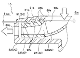
次に、遠心送風機10の詳細構成について説明する。本実施形態の遠心送風機10は、図2から図4に示すように、遠心ファン20と、ケース30とを備える。遠心ファン20は、回転軸の軸方向から吸い込んだ空気を径方向に吹き出す。ケース30は、この遠心ファン20を収容するとともに、内部へ空気を吸入する吸入口30aおよび外部へ空気を吹き出す吹出口30bを有する。
Next, the detailed configuration of the centrifugal blower 10 will be described. As shown in FIGS. 2 to 4, the centrifugal blower 10 of the present embodiment includes a centrifugal fan 20 and a case 30. The centrifugal fan 20 blows out the air sucked from the axial direction of the rotating shaft in the radial direction. The case 30 accommodates the centrifugal fan 20 and has a suction port 30a for sucking air into the inside and a blower outlet 30b for blowing air to the outside.
ケース30は、樹脂にて形成されており、上側ケース31と、下側ケース32とを有している。上側ケース31は、中心部に円形状の吸入口30aを有する。下側ケース32は平板矩形状を有し、下側ケース32には後述する電動モータの本体部が固定される。より具体的には、図3の分解斜視図に示すように、上側ケース31および下側ケース32の角部同士が、ボルト締め等で固定されている。
The case 30 is made of resin and has an upper case 31 and a lower case 32. The upper case 31 has a circular inlet 30a at the center. The lower case 32 has a flat rectangular shape, and a main body portion of an electric motor described later is fixed to the lower case 32. More specifically, as shown in the exploded perspective view of FIG. 3, the corners of the upper case 31 and the lower case 32 are fixed by bolting or the like.
上側ケース31に形成された吸入口30aは、遠心ファン20の回転軸と同軸上に配置されている。さらに、図2に示すように、ケース30の側面には、上側ケース31と下側ケース32との間の隙間によって、複数の吹出口30bが形成されている。この吹出口30bは、各角部同士の間に形成されるので、本実施形態の吹出口30bは、4箇所に形成されている。
The suction port 30a formed in the upper case 31 is arranged coaxially with the rotating shaft of the centrifugal fan 20. Further, as shown in FIG. 2, a plurality of air outlets 30 b are formed on the side surface of the case 30 by gaps between the upper case 31 and the lower case 32. Since this blower outlet 30b is formed between each corner | angular part, the blower outlet 30b of this embodiment is formed in four places.
遠心ファン20は、樹脂で形成されており、複数の羽根21、上面側プレート22、および下面側プレート23を有している。複数の羽根21は、回転軸の軸周りに円環状に配置されている。上面側プレート22は、回転軸の軸方向から見たときに円環状に形成された略平板状を有している。下面側プレート23は、略円錐状を有している。
The centrifugal fan 20 is made of resin and has a plurality of blades 21, an upper surface side plate 22, and a lower surface side plate 23. The plurality of blades 21 are arranged in an annular shape around the axis of the rotation shaft. The upper surface side plate 22 has a substantially flat plate shape formed in an annular shape when viewed from the axial direction of the rotation shaft. The lower surface side plate 23 has a substantially conical shape.
より具体的には、複数の羽根21は、回転軸の軸方向から見たときに、それぞれ径方向内側から外側に向かって回転方向の逆向きに傾斜した形状に形成されている。従って、本実施形態の遠心ファン20は、後向きファン(ターボファン)として構成されている。また、これらの複数の羽根21は、回転軸の軸方向の両側から上面側プレート22および下面側プレート23の円錐状側面の外周側との間に挟まれて固定されている。
More specifically, when viewed from the axial direction of the rotation shaft, the plurality of blades 21 are each formed in a shape inclined in the opposite direction of the rotation direction from the radially inner side to the outer side. Therefore, the centrifugal fan 20 of the present embodiment is configured as a backward-facing fan (turbo fan). Further, the plurality of blades 21 are sandwiched and fixed between the both sides in the axial direction of the rotation shaft and the outer peripheral sides of the conical side surfaces of the upper surface side plate 22 and the lower surface side plate 23.
上面側プレート22は、図4に示すように、上側ケース31の吸入口30aが形成された吸入側面31aに対向するように配置されている。上面側プレート22の中心部には、上側ケース31の吸入口30aを介して吸入された空気を遠心ファン20の内部へ流入させる円形状のファン側吸入孔20aが形成されている。このファン側吸入孔20aは、回転軸と同軸上に配置され、上面側プレート22の最内周部を形成している。
As shown in FIG. 4, the upper surface side plate 22 is disposed so as to face the suction side surface 31a in which the suction port 30a of the upper case 31 is formed. A circular fan side suction hole 20 a through which air sucked through the suction port 30 a of the upper case 31 flows into the centrifugal fan 20 is formed at the center of the upper surface side plate 22. The fan-side suction hole 20 a is disposed coaxially with the rotation shaft, and forms the innermost peripheral portion of the upper surface side plate 22.
下面側プレート23の円錐状側面の内周側には、図示しない電動モータが配置されており、この電動モータの回転軸が下面側プレート23に連結されている。前述の如く、電動モータの本体部は下側ケース32に固定されている。従って、電動モータから遠心ファン20(具体的には、下面側プレート23)へ回転駆動力が伝達されると、遠心ファン20がケース30内で回転する。
An electric motor (not shown) is disposed on the inner peripheral side of the conical side surface of the lower surface side plate 23, and the rotating shaft of the electric motor is connected to the lower surface side plate 23. As described above, the main body of the electric motor is fixed to the lower case 32. Therefore, when the rotational driving force is transmitted from the electric motor to the centrifugal fan 20 (specifically, the lower surface side plate 23), the centrifugal fan 20 rotates in the case 30.
さらに、本実施形態では、遠心ファン20が回転した際に、遠心ファン20とケース30が直接接触しないように、遠心ファン20とケース30との間に隙間が形成されている。これにより、遠心ファン20とケース30との間の摺動抵抗が抑制されている。なお、電動モータは、図示しない制御装置から出力される制御電圧によって、その作動が制御される。
Further, in the present embodiment, a gap is formed between the centrifugal fan 20 and the case 30 so that the centrifugal fan 20 and the case 30 do not directly contact when the centrifugal fan 20 rotates. Thereby, the sliding resistance between the centrifugal fan 20 and the case 30 is suppressed. The operation of the electric motor is controlled by a control voltage output from a control device (not shown).
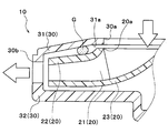
また、本実施形態の上側ケース31の吸入側面31aには、図4に示すように、遠心ファン20の上面側プレート22へ向かって回転軸の軸方向へ突出する2つのケース側突出部31bが形成されている。これらの2つケース側突出部31bは、その先端部22bが上面側プレート22に接触しない寸法に形成されている。
Further, on the suction side surface 31a of the upper case 31 of the present embodiment, as shown in FIG. 4, there are two case-side protruding portions 31b that protrude in the axial direction of the rotating shaft toward the upper surface side plate 22 of the centrifugal fan 20. Is formed. These two case-side protruding portions 31b are formed to have dimensions that do not contact the top surface side plate 22 with the tip portions 22b.
さらに、これらの2つのケース側突出部31bは、回転軸の軸方向から見たときに互いに異なる径の円環状に形成されて、回転軸と同軸上に配置されている。また、2つのケース側突出部31b同士の径方向の間には、半固体状物質からなるシール材としてのグリスGが全周に亘って充填されている。より具体的には、本実施形態では、グリスGは、粘度が0.024Pa・S程度、動粘度が26cSt程度である。
Furthermore, these two case-side protruding portions 31b are formed in an annular shape having different diameters when viewed from the axial direction of the rotating shaft, and are arranged coaxially with the rotating shaft. Moreover, between the radial directions of the two case side protrusions 31b, grease G as a sealing material made of a semi-solid substance is filled over the entire circumference. More specifically, in this embodiment, the grease G has a viscosity of about 0.024 Pa · S and a kinematic viscosity of about 26 cSt.
一方、遠心ファン20の上面側プレート22には、上側ケース31の吸入側面31aへ向かって回転軸の軸方向へ突出する1つのファン側突出部22aが形成されている。このファン側突出部22aも、回転軸の軸方向から見たときに円環状に形成されて、回転軸と同軸上に配置されている。
On the other hand, the upper surface side plate 22 of the centrifugal fan 20 is formed with one fan side protruding portion 22a that protrudes in the axial direction of the rotating shaft toward the suction side surface 31a of the upper case 31. The fan-side protrusion 22a is also formed in an annular shape when viewed from the axial direction of the rotating shaft, and is arranged coaxially with the rotating shaft.
さらに、ファン側突出部22aの径は、内周側のケース側突出部31bの径よりも大きく、かつ、外周側のケース側突出部31bの径よりも小さく形成されている。これにより、ファン側突出部22aの先端部22bは、2つのケース側突出部31b同士の間に突出して、吸入側面31aに接触することなく、2つのケース側突出部31b同士の間に充填されたグリスGに全周に亘って接触している。
Furthermore, the diameter of the fan-side protruding portion 22a is formed to be larger than the diameter of the case-side protruding portion 31b on the inner peripheral side and smaller than the diameter of the case-side protruding portion 31b on the outer peripheral side. Thereby, the front-end | tip part 22b of the fan side protrusion part 22a protrudes between two case side protrusion parts 31b, and is filled between two case side protrusion parts 31b, without contacting the suction | inhalation side surface 31a. The grease G is in contact with the entire circumference.
ファン側突出部22aの先端部22bは、図4に示すように、軸方向断面における断面形状が突出方向に向かって徐々に先細る形状に形成されている。軸方向断面における断面形状とは、すなわち、回転軸を含む断面における断面形状である。より具体的には、本実施形態の先端部22bの軸方向断面における断面形状は、鋭角的に尖った形状に形成されている。
As shown in FIG. 4, the tip 22b of the fan-side protruding portion 22a is formed in a shape in which the cross-sectional shape in the axial section gradually tapers in the protruding direction. The cross-sectional shape in the cross section in the axial direction is a cross-sectional shape in a cross section including the rotation axis. More specifically, the cross-sectional shape in the axial cross section of the tip end portion 22b of the present embodiment is formed in an acutely sharp shape.
つまり、本実施形態では、ケース側突出部31bが一方の突出部を構成し、ファン側突出部22a他方の突出部を構成している。また、図4から明らかなように、ケース側突出部31bおよびファン側突出部22aは、遠心ファン20の最外周部よりも最内周部(ファン側吸入孔20a)に近い位置に位置している。
That is, in the present embodiment, the case side protruding portion 31b constitutes one protruding portion, and the fan side protruding portion 22a constitutes the other protruding portion. As is clear from FIG. 4, the case-side protrusion 31 b and the fan-side protrusion 22 a are located closer to the innermost peripheral part (fan-side suction hole 20 a) than the outermost peripheral part of the centrifugal fan 20. Yes.
次に、上記構成における本実施形態の作動について説明する。本実施形態の遠心送風機10では、制御装置が電動モータを作動させると、遠心ファン20が回転する。これにより、シートSの表面近傍の空気が、ケース30の吸入口30aから吸い込まれて吹出口30bから吹き出される。本実施形態の遠心送風機10は、上記の如く作動してシート空調装置において、車室内の空気を吸い込む。
Next, the operation of this embodiment in the above configuration will be described. In the centrifugal blower 10 of the present embodiment, the centrifugal fan 20 rotates when the control device operates the electric motor. Thereby, the air near the surface of the sheet S is sucked from the suction port 30a of the case 30 and blown out from the blower outlet 30b. The centrifugal blower 10 according to the present embodiment operates as described above, and sucks air in the vehicle compartment in the seat air conditioner.
ここで、この種の遠心送風機では、遠心ファンをケース内で回転させる。従って、遠心ファンとケースとの間の摺動抵抗を抑制し、遠心ファンを回転させるために必要な回転駆動力(軸動力)を低減させることで、ファン効率ηfを向上させることができる。従って、本実施形態の遠心送風機10と同様に、遠心ファンをケースに接触させないように配置する。
Here, in this type of centrifugal blower, the centrifugal fan is rotated inside the case. Therefore, the fan efficiency ηf can be improved by suppressing the sliding resistance between the centrifugal fan and the case and reducing the rotational driving force (shaft power) required for rotating the centrifugal fan. Therefore, like the centrifugal blower 10 of the present embodiment, the centrifugal fan is disposed so as not to contact the case.
ところが、遠心ファンをケースに接触させないために、遠心ファンとケースとの間に形成される隙間の寸法を大きく設定してしまうと、この隙間を介して遠心ファンから吹き出された空気が吸入口側へ逆流してしまうため、却ってファン効率ηfが低下してしまうことがある。
However, if the size of the gap formed between the centrifugal fan and the case is set large so that the centrifugal fan does not contact the case, the air blown from the centrifugal fan through this gap will be However, the fan efficiency ηf may decrease instead.
これに対して、本実施形態の遠心送風機10では、2つのケース側突出部31b同士の間にグリスGが充填され、さらに、ファン側突出部22aの先端部22bをグリスGに接触させている。これにより、ケース30の吸入側面31aと遠心ファン20の上面側プレート22との間の隙間を介して、遠心ファン20から吹き出された空気が吸入口30a側へ逆流してしまうことを防止できる。
On the other hand, in the centrifugal blower 10 of the present embodiment, the grease G is filled between the two case side protrusions 31b, and the tip 22b of the fan side protrusion 22a is in contact with the grease G. . Thereby, it is possible to prevent the air blown out from the centrifugal fan 20 from flowing backward to the suction port 30a through the gap between the suction side surface 31a of the case 30 and the upper surface side plate 22 of the centrifugal fan 20.
従って、遠心ファン20から吹き出された空気が、再びファン側吸入孔20aから吸入されてしまうことによって、ファン効率ηfが低下してしまうことを防止できる。
Therefore, it is possible to prevent the fan efficiency ηf from being lowered by the air blown from the centrifugal fan 20 being sucked again from the fan-side suction hole 20a.
なお、本実施形態の如く、遠心ファン20が後向きファンとして構成されている遠心送風機10では、遠心ファン20の入口側の空気圧(吸入圧)に対して、出口側の空気圧(吐出圧)が高くなりやすい。その結果、遠心ファン20から吹き出された空気が吸入口30a側へ逆流しやすい。従って、後向きファンを備える遠心送風機において、本実施形態の如く逆流を防止できることは、ファン効率ηfの向上のために極めて有効である。
Note that, in the centrifugal blower 10 in which the centrifugal fan 20 is configured as a backward fan as in this embodiment, the air pressure (discharge pressure) on the outlet side is higher than the air pressure (suction pressure) on the inlet side of the centrifugal fan 20. Prone. As a result, the air blown out from the centrifugal fan 20 tends to flow backward toward the suction port 30a. Therefore, in a centrifugal fan provided with a rearward fan, the ability to prevent backflow as in this embodiment is extremely effective for improving fan efficiency ηf.
より具体的には、本開示者らの検討によれば、本実施形態に対して2つのケース側突出部31b同士の間にグリスGが充填されていない遠心送風機において、遠心ファン20の軸動力を増加させることなく、逆流を防止することができれば、図5の破線から一点鎖線への変化に示すように、ファン効率ηfを15%程度向上可能であることが判っている。2つのケース側突出部31b同士の間にグリスGが充填されていない遠心送風機とは、すなわち、逆流が生じ得る、比較例としての遠心送風機である。この比較例としての遠心送風機を、以下、比較用送風機と言う。比較用送風機では、逆流が生じてしまうものの、遠心ファン20とグリスGとの間に摺動抵抗が生じない。
More specifically, according to the present inventors' investigation, in the centrifugal blower in which the grease G is not filled between the two case side protrusions 31b with respect to the present embodiment, the shaft power of the centrifugal fan 20 is It has been found that if backflow can be prevented without increasing the fan efficiency, the fan efficiency ηf can be improved by about 15%, as shown by the change from the broken line to the alternate long and short dash line in FIG. The centrifugal blower in which the grease G is not filled between the two case-side protruding portions 31b is a centrifugal blower as a comparative example in which a backflow can occur. Hereinafter, the centrifugal blower as the comparative example is referred to as a comparative blower. In the comparative blower, a back flow is generated, but no sliding resistance is generated between the centrifugal fan 20 and the grease G.
さらに、本実施形態の遠心送風機10では、遠心ファン20とケース30が、直接接触していない。従って、遠心ファン20とケース30との間の摺動抵抗を抑制できる。これに加えて、ファン側突出部22aの先端部22bの軸方向断面における断面形状が、突出方向に向かって徐々に先細る形状に形成されている。従って、ファン側突出部22aとグリスSとの接触面積を低減させて、ファン側突出部22aとグリスGとの間の摺動抵抗が増加してしまうことも抑制できる。
Furthermore, in the centrifugal blower 10 of the present embodiment, the centrifugal fan 20 and the case 30 are not in direct contact. Therefore, sliding resistance between the centrifugal fan 20 and the case 30 can be suppressed. In addition to this, the cross-sectional shape in the axial cross section of the tip end portion 22b of the fan-side protruding portion 22a is formed into a shape that gradually tapers in the protruding direction. Therefore, the contact area between the fan-side protrusion 22a and the grease S can be reduced, and an increase in the sliding resistance between the fan-side protrusion 22a and the grease G can be suppressed.
具体的には、ファン側突出部22aの先端部22bのうちグリスGと接触している部分の面積をAとし、遠心ファン20が回転した際のファン側突出部22aとグリスGとの相対速度をUとする。ファン側突出部22aが受ける荷重Fは、以下数式F1から求めることができる。荷重Fとは、ファン側突出部22aとグリスGとの間の摺動抵抗に相当する。
Specifically, the area of the tip 22b of the fan-side protrusion 22a that is in contact with the grease G is A, and the relative speed between the fan-side protrusion 22a and the grease G when the centrifugal fan 20 rotates. Let U be U. The load F received by the fan-side protruding portion 22a can be obtained from the following formula F1. The load F corresponds to the sliding resistance between the fan-side protruding portion 22a and the grease G.
F=μ×(A×U)/h…(F1)
なお、μはグリスSの粘度であって、hはグリスSの厚さである。 F = μ × (A × U) / h (F1)
Note that μ is the viscosity of the grease S, and h is the thickness of the grease S.
なお、μはグリスSの粘度であって、hはグリスSの厚さである。 F = μ × (A × U) / h (F1)
Note that μ is the viscosity of the grease S, and h is the thickness of the grease S.
そして、本開示者らの検討によれば、本実施形態の遠心送風機10では、前述した比較用送風機に対して、10%程度の軸動力の増加で逆流を防止できることが判った。
Then, according to the study by the present inventors, it has been found that the centrifugal blower 10 of the present embodiment can prevent backflow with an increase in shaft power of about 10% compared to the above-described comparative blower.
つまり、本実施形態の遠心送風機10によれば、遠心ファン20から吹き出された空気がケース30の吸入口30a側へ逆流してしまうことの抑制、遠心ファン20の軸動力が増加してしまうことの抑制の両立を図ることができる。その結果、本実施形態の遠心送風機10によれば、図5の実線に示すように、比較用送風機に対して、ファン効率ηfを5%程度向上させることができる。
That is, according to the centrifugal blower 10 of the present embodiment, the air blown from the centrifugal fan 20 is prevented from flowing back to the suction port 30a side of the case 30, and the axial power of the centrifugal fan 20 is increased. Can be achieved at the same time. As a result, according to the centrifugal blower 10 of the present embodiment, the fan efficiency ηf can be improved by about 5% with respect to the comparative blower, as shown by the solid line in FIG.
ここで、一般的な送風機では、図6に示すように、ファン効率ηfを向上させることによって、送風機の比騒音Lsを低減できることが知られている。従って、本実施形態の遠心送風機10においても、上述したファン効率ηfの向上効果によって、比騒音LSを低減させることができる。
Here, it is known that a general blower can reduce the specific noise Ls of the blower by improving the fan efficiency ηf as shown in FIG. Therefore, also in the centrifugal blower 10 of the present embodiment, the specific noise LS can be reduced by the effect of improving the fan efficiency ηf described above.
より詳細には、本実施形態の遠心送風機10では、上述したファン効率ηf向上効果によって、図7の実線に示すように、破線で示す比較用送風機よりも、流量係数φに対する圧力係数ψを向上させることができる。このことは、本実施形態の遠心送風機10によれば、比較用送風機よりも、低回転で所望の作動点(風量および圧力)を確保できることを意味している。
More specifically, in the centrifugal blower 10 of the present embodiment, the pressure coefficient ψ with respect to the flow coefficient φ is improved by the above-described effect of improving the fan efficiency ηf, as shown by the solid line in FIG. Can be made. This means that according to the centrifugal blower 10 of the present embodiment, a desired operating point (air volume and pressure) can be secured at a lower rotation than the comparative blower.
従って、本実施形態の遠心送風機10によれば、図8の実線に示すように、破線で示す比較用送風機よりも、所望の作動点における比騒音Lsを低減させることができる。なお、図5から図8にて用いた流量係数φおよび圧力係数ψは、2つのファンの性能を同一の作動条件で比較するために、それぞれ送風機から吹き出される空気の風量(流量)および送風機から吹き出される空気圧力を無次元化した値である。同一の作動条件とは、例えば、2つのファンを同一ファン径となるように形成し、同一回転数で作動させる条件である。
Therefore, according to the centrifugal blower 10 of the present embodiment, as shown by the solid line in FIG. 8, the specific noise Ls at a desired operating point can be reduced as compared with the comparative blower indicated by the broken line. Note that the flow rate coefficient φ and the pressure coefficient ψ used in FIGS. 5 to 8 are the air volume (flow rate) of the air blown from the blower and the blower in order to compare the performance of the two fans under the same operating conditions. This is a value obtained by making the air pressure blown from the air non-dimensional. The same operating condition is, for example, a condition in which two fans are formed to have the same fan diameter and are operated at the same rotational speed.
また、本実施形態の遠心送風機10では、シール材として半固体状物質からなるグリスGを採用している。従って、ファン側突出部22aを形成する際に、ファン側突出部22aの突出方向の寸法が狙いの寸法と僅かに異なってしまっても、グリスGの充填量を調整することで、ファン側突出部22aの先端部22bを容易にグリスGに接触させることができる。つまり、ファン側突出部22aを形成する際に、高度な公差管理を要することなく容易に形成することができる。
Moreover, in the centrifugal blower 10 of the present embodiment, grease G made of a semi-solid substance is employed as a sealing material. Therefore, when the fan-side protrusion 22a is formed, even if the dimension in the protrusion direction of the fan-side protrusion 22a is slightly different from the target dimension, by adjusting the filling amount of the grease G, the fan-side protrusion The tip 22b of the portion 22a can be easily brought into contact with the grease G. That is, when forming the fan-side protruding portion 22a, it can be easily formed without requiring sophisticated tolerance management.
また、本実施形態の遠心送風機10では、ケース側突出部31bを複数設けて、ケース側突出部31b同士の間にグリスGを充填している。従って、ファン側突出部22aを複数設けて、ファン側突出部22aの間にグリスGを充填する場合のように、遠心ファン20の重量を増加させて軸動力を増加させてしまうことがない。さらに、遠心ファン20が回転した際に生じる遠心力によって、グリスGが剥がれ落ちてしまうこともない。
Further, in the centrifugal blower 10 of the present embodiment, a plurality of case side protrusions 31b are provided, and the grease G is filled between the case side protrusions 31b. Therefore, unlike the case where a plurality of fan-side protrusions 22a are provided and the grease G is filled between the fan-side protrusions 22a, the weight of the centrifugal fan 20 is not increased and the shaft power is not increased. Further, the grease G is not peeled off by the centrifugal force generated when the centrifugal fan 20 rotates.
また、本実施形態の遠心送風機10では、ケース側突出部31bおよびファン側突出部22aが、上面側プレート22の最外周部よりも最内周部(ファン側吸入孔20a)に近い位置に位置している。従って、最外周部に近い位置に位置している場合に対して、ファン側突出部22aとグリスGとの接触面積を減らすことができる。従って、ファン側突出部22aとグリスGとの間の摺動抵抗が増加してしまうことを効果的に抑制できる。
In the centrifugal blower 10 of the present embodiment, the case-side protruding portion 31b and the fan-side protruding portion 22a are positioned closer to the innermost peripheral portion (fan-side suction hole 20a) than the outermost peripheral portion of the upper surface side plate 22. is doing. Therefore, the contact area between the fan-side protruding portion 22a and the grease G can be reduced as compared with the case where the position is close to the outermost peripheral portion. Therefore, it is possible to effectively suppress an increase in the sliding resistance between the fan-side protruding portion 22a and the grease G.
また、本実施形態の遠心送風機10では、ファン側突出部22aが、上面側プレート22の最内周部(ファン側吸入孔20a)より外周側に位置している。従って、ファン側吸入孔20aの形状の影響を受けることなく、ファン側突出部22aの形状を、確実かつ容易に、ケース側突出部31bに適合する円環状に形成することができる。
(第2実施形態)
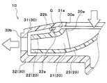
本実施形態では、図9に示すように、ケース側突出部31bおよびファン側突出部22aの構成を変更した例を説明する。なお、図9は、第1実施形態の図4に対応する図面であり、第1実施形態と同一もしくは均等部分には同一の符号を付している。このことは、以下の図10から図12においても同様である。 Further, in thecentrifugal blower 10 of the present embodiment, the fan-side protruding portion 22a is positioned on the outer peripheral side of the innermost peripheral portion (fan-side suction hole 20a) of the upper surface side plate 22. Therefore, the shape of the fan-side protrusion 22a can be reliably and easily formed in an annular shape that fits the case-side protrusion 31b without being affected by the shape of the fan-side suction hole 20a.
(Second Embodiment)
In the present embodiment, as shown in FIG. 9, an example will be described in which the configurations of the caseside protruding portion 31b and the fan side protruding portion 22a are changed. FIG. 9 is a drawing corresponding to FIG. 4 of the first embodiment, and the same or equivalent parts as in the first embodiment are denoted by the same reference numerals. This also applies to FIGS. 10 to 12 below.
(第2実施形態)
本実施形態では、図9に示すように、ケース側突出部31bおよびファン側突出部22aの構成を変更した例を説明する。なお、図9は、第1実施形態の図4に対応する図面であり、第1実施形態と同一もしくは均等部分には同一の符号を付している。このことは、以下の図10から図12においても同様である。 Further, in the
(Second Embodiment)
In the present embodiment, as shown in FIG. 9, an example will be described in which the configurations of the case
具体的には、ケース側突出部31bおよびファン側突出部22aは、いずれも複数(本実施形態では、3つ)設けられている。図9の軸方向断面に示すように、各ケース側突出部31bの径および各ファン側突出部22aの径が、交互に順次大きくなっている。つまり、ケース側突出部31bおよびファン側突出部22aは、回転軸の軸方向から見たときに径方向に向かって交互に配置されている。
Specifically, a plurality of case side protrusions 31b and fan side protrusions 22a are provided (three in this embodiment). As shown in the axial cross section of FIG. 9, the diameters of the case-side protrusions 31b and the diameters of the fan-side protrusions 22a are alternately increased. That is, the case side protrusions 31b and the fan side protrusions 22a are alternately arranged in the radial direction when viewed from the axial direction of the rotating shaft.
このように、互いに対向して突出するケース側突出部31bおよびファン側突出部22aが径方向に向かって交互に配置されることによって、本実施形態のケース側突出部31bおよびファン側突出部22aは、ケース30の吸入側面31aと遠心ファン20の上面側プレート22との間に形成される隙間空間内にラビリンスシール構造を構成している。
As described above, the case-side protrusions 31b and the fan-side protrusions 22a of the present embodiment are arranged by alternately disposing the case-side protrusions 31b and the fan-side protrusions 22a facing each other in the radial direction. Constitutes a labyrinth seal structure in a gap space formed between the suction side surface 31 a of the case 30 and the upper surface side plate 22 of the centrifugal fan 20.
さらに、本実施形態では、図9に示すように、ラビリンスシール構造の内周側における吸入側面31aと上面側プレート22との間の隙間の寸法δinが、ラビリンスシールの外周側における吸入側面31aと上面側プレート22との間の隙間の寸法δoutよりも小さくなっている。その他の遠心送風機10の構成および作動は第1実施形態と同様である。
Furthermore, in this embodiment, as shown in FIG. 9, the dimension δin of the gap between the suction side 31a on the inner peripheral side of the labyrinth seal structure and the upper surface side plate 22 is the same as the suction side 31a on the outer peripheral side of the labyrinth seal. It is smaller than the dimension δout of the gap with the upper surface side plate 22. Other configurations and operations of the centrifugal fan 10 are the same as those in the first embodiment.
従って、本実施形態の遠心送風機10を作動させた際にも、第1実施形態と同様に、シート空調装置において、車室内の空気を吸い込むことができる。
Therefore, even when the centrifugal blower 10 of the present embodiment is operated, the air in the vehicle compartment can be sucked in the seat air conditioner as in the first embodiment.
さらに、本実施形態の遠心送風機10によれば、複数のケース側突出部31bおよび複数のファン側突出部22aが、吸入側面31aと上面側プレート22との間に形成される隙間内にラビリンスシールを構成している。さらに、ラビリンスシールの内周側(回転軸側)における隙間の寸法δinが、外周側における隙間の寸法δoutよりも小さくなっている。
Furthermore, according to the centrifugal blower 10 of the present embodiment, the plurality of case-side protrusions 31b and the plurality of fan-side protrusions 22a are in a labyrinth seal within a gap formed between the suction side surface 31a and the upper surface side plate 22. Is configured. Furthermore, the clearance dimension δin on the inner peripheral side (rotating shaft side) of the labyrinth seal is smaller than the clearance dimension δout on the outer peripheral side.
従って、ケース30の吸入側面31aと遠心ファン20の上面側プレート22との間の隙間を介して、遠心ファン20から吹き出された空気が吸入口30a側へ逆流してしまうことを効果的に抑制できる。
Therefore, the air blown out from the centrifugal fan 20 through the gap between the suction side surface 31a of the case 30 and the upper surface side plate 22 of the centrifugal fan 20 is effectively suppressed from flowing backward to the suction port 30a side. it can.
さらに、本実施形態の遠心送風機10では、遠心ファン20とケース30が、直接接触していないので、遠心ファン20とケース30との間の摺動抵抗を抑制できる。この際、遠心ファン20の内周側(回転軸側)は外周側よりも振動等による変位量が少ない。従って、遠心ファン20およびケース30のうちラビリンスシールの内周側を形成する部位同士が接触して摺動抵抗を増加させてしまうことも抑制できる。
Furthermore, in the centrifugal blower 10 of this embodiment, since the centrifugal fan 20 and the case 30 are not in direct contact, the sliding resistance between the centrifugal fan 20 and the case 30 can be suppressed. At this time, the amount of displacement due to vibration or the like is smaller on the inner peripheral side (rotating shaft side) of the centrifugal fan 20 than on the outer peripheral side. Therefore, it can also be suppressed that the portions forming the inner peripheral side of the labyrinth seal in the centrifugal fan 20 and the case 30 come into contact with each other and increase the sliding resistance.
つまり、本実施形態の遠心送風機10においても、遠心ファン20から吹き出された空気がケース30の吸入口30a側へ逆流してしまうことの抑制、遠心ファン20の軸動力が増加してしまうことの抑制の両立を図ることができる。
(第3実施形態)
本実施形態では、第1実施形態の変形例を説明する。本実施形態の遠心送風機10では、図10に示すように、第1実施形態に対して、ファン側突出部22aおよびケース側突出部31bが廃止されている。 That is, also in thecentrifugal blower 10 of the present embodiment, the air blown out from the centrifugal fan 20 is prevented from flowing back to the suction port 30a side of the case 30, and the axial power of the centrifugal fan 20 is increased. It is possible to achieve both suppression.
(Third embodiment)
In the present embodiment, a modification of the first embodiment will be described. In thecentrifugal blower 10 of this embodiment, as shown in FIG. 10, the fan side protrusion 22a and the case side protrusion 31b are abolished with respect to the first embodiment.
(第3実施形態)
本実施形態では、第1実施形態の変形例を説明する。本実施形態の遠心送風機10では、図10に示すように、第1実施形態に対して、ファン側突出部22aおよびケース側突出部31bが廃止されている。 That is, also in the
(Third embodiment)
In the present embodiment, a modification of the first embodiment will be described. In the
このため、本実施形態のグリスGは、ケース30の吸入側面31aと遠心ファン20の上面側プレート22との間の隙間に配置されている。さらに、グリスGは、吸入側面31aおよび上面側プレート22の双方に接触しているとともに、軸方向から見たときに回転軸の軸周りに円環状に配置されている。その他の構成は、第1施形態と同様である。
For this reason, the grease G of the present embodiment is disposed in a gap between the suction side surface 31 a of the case 30 and the upper surface side plate 22 of the centrifugal fan 20. Furthermore, the grease G is in contact with both the suction side surface 31a and the upper surface side plate 22, and is arranged in an annular shape around the axis of the rotation shaft when viewed from the axial direction. Other configurations are the same as those of the first embodiment.
従って、本実施形態の遠心送風機10を作動させた際にも、第1実施形態と同様に、シート空調装置において、車室内の空気を吸い込むことができる。
Therefore, even when the centrifugal blower 10 of the present embodiment is operated, the air in the vehicle compartment can be sucked in the seat air conditioner as in the first embodiment.
なお、「グリスGは、吸入側面31aおよび上面側プレート22の双方に接触している」とは、グリスGが、吸入側面31aおよび上面側プレート22のうち、面状に形成された部位に接触しているという意味に限定されない。
Note that “the grease G is in contact with both the suction side surface 31 a and the upper surface side plate 22” means that the grease G is in contact with a portion of the suction side surface 31 a and the upper surface side plate 22 that is formed in a planar shape. It is not limited to the meaning of doing.
例えば、吸入側面31aあるいは上面側プレート22が、突出部や凹部を有する場合には、グリスGが、当該突出部の先端部や凹部の内部に接触していることも含む意味である。
For example, when the suction side surface 31a or the upper surface side plate 22 has a protrusion or a recess, it means that the grease G is in contact with the inside of the tip or the recess of the protrusion.
さらに、本実施形態の遠心送風機10によれば、シール材としてのグリスGが、吸入側面31aと上面側プレート22との間の隙間に配置されている。従って、第1実施形態と同様に、吸入側面31aと上面側プレート22との間の隙間を介して、遠心ファン20から吹き出された空気が吸入口30a側へ逆流してしまうことを防止できる。
Furthermore, according to the centrifugal blower 10 of the present embodiment, the grease G as the sealing material is disposed in the gap between the suction side surface 31a and the upper surface side plate 22. Therefore, similarly to the first embodiment, it is possible to prevent the air blown out from the centrifugal fan 20 from flowing back to the suction port 30a side through the gap between the suction side surface 31a and the upper surface side plate 22.
以上の如く、本実施形態の遠心送風機10では、ファン側突出部22aおよびケース側突出部31bが廃止されている。従って、吸入側面31aと上面側プレート22との間の隙間にグリスGを配置するという極めて簡素な構成で、上述した逆流防止効果を得ることができる。
As described above, in the centrifugal blower 10 of the present embodiment, the fan side protruding portion 22a and the case side protruding portion 31b are abolished. Therefore, the above-described backflow prevention effect can be obtained with a very simple configuration in which the grease G is disposed in the gap between the suction side surface 31a and the upper surface side plate 22.
その一方で、本実施形態の遠心送風機10では、遠心ファン20の回転に伴ってグリスGに遠心力が作用するので、グリスGが外周側に移動しやすい。従って、本実施形態の遠心送風機10は、第1実施形態よりも低い回転数帯で遠心ファン20を回転させる遠心送風機として用いられることが望ましい。
On the other hand, in the centrifugal blower 10 of the present embodiment, since the centrifugal force acts on the grease G as the centrifugal fan 20 rotates, the grease G easily moves to the outer peripheral side. Therefore, it is desirable that the centrifugal blower 10 of the present embodiment be used as a centrifugal blower that rotates the centrifugal fan 20 at a lower rotational speed range than the first embodiment.
また、本実施形態の遠心送風機10では、シール材の剥離を抑制するために、第1実施形態よりも吸入側面31aと上面側プレート22との間の隙間の距離を短縮化しておくことが望ましい。
(第4実施形態)
本実施形態では、第1実施形態の変形例を説明する。本実施形態の遠心送風機10では、図11に示すように、第1実施形態に対して、ケース側突出部31bが廃止されている。そして、上面側プレート22のファン側突出部22aの先端部22bが、吸入側面31aと上面側プレート22との間の隙間に配置されたグリスGに接触している。その他の構成は、第1実施形態と同様である。 Further, in thecentrifugal blower 10 of the present embodiment, in order to suppress the peeling of the sealing material, it is desirable to shorten the gap distance between the suction side surface 31a and the upper surface side plate 22 as compared with the first embodiment. .
(Fourth embodiment)
In the present embodiment, a modification of the first embodiment will be described. In thecentrifugal blower 10 of this embodiment, as shown in FIG. 11, the case side protrusion part 31b is abolished with respect to 1st Embodiment. The front end portion 22 b of the fan-side protrusion 22 a of the upper surface side plate 22 is in contact with the grease G disposed in the gap between the suction side surface 31 a and the upper surface side plate 22. Other configurations are the same as those of the first embodiment.
(第4実施形態)
本実施形態では、第1実施形態の変形例を説明する。本実施形態の遠心送風機10では、図11に示すように、第1実施形態に対して、ケース側突出部31bが廃止されている。そして、上面側プレート22のファン側突出部22aの先端部22bが、吸入側面31aと上面側プレート22との間の隙間に配置されたグリスGに接触している。その他の構成は、第1実施形態と同様である。 Further, in the
(Fourth embodiment)
In the present embodiment, a modification of the first embodiment will be described. In the
従って、本実施形態の遠心送風機10を作動させた際にも、第1実施形態と同様に、シート空調装置において、車室内の空気を吸い込むことができる。さらに、吸入側面31aと上面側プレート22との間の隙間を介して、遠心ファン20から吹き出された空気が吸入口30a側へ逆流してしまうことを防止できる等、第1実施形態と同様の効果を得ることができる。
(第5実施形態)
本実施形態では、第1実施形態の変形例を説明する。本実施形態の遠心送風機10では、図12に示すように、第1実施形態に対して、ケース側突出部31bを廃止するとともに、ケース30の吸入側面31aのうち上面側プレート22に対向する側の面に凹部31cを形成している。 Therefore, when thecentrifugal blower 10 of this embodiment is operated, the air in the vehicle compartment can be sucked in the seat air conditioner, as in the first embodiment. Further, the air blown out from the centrifugal fan 20 can be prevented from flowing back to the suction port 30a through the gap between the suction side surface 31a and the upper surface side plate 22, and the same as in the first embodiment. An effect can be obtained.
(Fifth embodiment)
In the present embodiment, a modification of the first embodiment will be described. In thecentrifugal blower 10 of the present embodiment, as shown in FIG. 12, the case side protruding portion 31b is abolished and the side of the suction side surface 31a of the case 30 that faces the upper surface side plate 22 as shown in FIG. A recess 31c is formed on the surface.
(第5実施形態)
本実施形態では、第1実施形態の変形例を説明する。本実施形態の遠心送風機10では、図12に示すように、第1実施形態に対して、ケース側突出部31bを廃止するとともに、ケース30の吸入側面31aのうち上面側プレート22に対向する側の面に凹部31cを形成している。 Therefore, when the
(Fifth embodiment)
In the present embodiment, a modification of the first embodiment will be described. In the
凹部31cは、回転軸の軸方向から見たときに回転軸の軸周りに円環状に形成されており、ファン側突出部22aから離れる側に凹んでいる。ファン側突出部22aおよび凹部31cは、軸方向から見たときに互いに重合して配置されている。ファン側突出部22aは、先端部22bが凹部31cの内部へ至るように突出している。
The recess 31c is formed in an annular shape around the axis of the rotating shaft when viewed from the axial direction of the rotating shaft, and is recessed on the side away from the fan-side protruding portion 22a. The fan-side protrusion 22a and the recess 31c are arranged so as to overlap each other when viewed from the axial direction. The fan-side protrusion 22a protrudes so that the tip 22b reaches the inside of the recess 31c.
さらに、本実施形態のグリスGは、凹部31cの内部に全周に亘って充填されている。そして、ファン側突出部22aの先端部22bは、凹部31cの内部に充填されたグリスGに接触している。その他の構成は、第1実施形態と同様である。
Furthermore, the grease G of this embodiment is filled in the inside of the recess 31c over the entire circumference. And the front-end | tip part 22b of the fan side protrusion part 22a is contacting the grease G with which the inside of the recessed part 31c was filled. Other configurations are the same as those of the first embodiment.
従って、本実施形態の遠心送風機10を作動させた際にも、第1実施形態と同様に、シート空調装置において、車室内の空気を吸い込むことができる。さらに、吸入側面31aと上面側プレート22との間の隙間を介して、遠心ファン20から吹き出された空気が吸入口30a側へ逆流してしまうことを防止できる等、第1実施形態と同様の効果を得ることができる。
(他の実施形態)
本開示は上述の実施形態に限定されることなく、本開示の趣旨を逸脱しない範囲内で、以下のように種々変形可能である。 Therefore, when thecentrifugal blower 10 of this embodiment is operated, the air in the vehicle compartment can be sucked in the seat air conditioner, as in the first embodiment. Further, the air blown out from the centrifugal fan 20 can be prevented from flowing back to the suction port 30a through the gap between the suction side surface 31a and the upper surface side plate 22, and the same as in the first embodiment. An effect can be obtained.
(Other embodiments)
The present disclosure is not limited to the above-described embodiment, and can be variously modified as follows without departing from the spirit of the present disclosure.
(他の実施形態)
本開示は上述の実施形態に限定されることなく、本開示の趣旨を逸脱しない範囲内で、以下のように種々変形可能である。 Therefore, when the
(Other embodiments)
The present disclosure is not limited to the above-described embodiment, and can be variously modified as follows without departing from the spirit of the present disclosure.
(1)上述の第1実施形態では、ケース側突出部31bによって特許請求の範囲に記載された一方の突出部を構成した例を説明した。しかしながら、ファン側突出部22aを複数設け、ファン側突出部22aによって一方の突出部を構成し、ケース側突出部31bによって他方の突出部を構成してもよい。
(1) In the above-described first embodiment, the example in which one protrusion described in the claims is configured by the case-side protrusion 31b has been described. However, a plurality of fan-side protrusions 22a may be provided, one protrusion may be configured by the fan-side protrusion 22a, and the other protrusion may be configured by the case-side protrusion 31b.
さらに、ケース側突出部31bの数量およびファン側突出部22aの数量は第1実施形態で説明した数量に限定されることなく、ケース側突出部31bおよびファン側突出部22aの双方を複数設けてもよい。
Further, the number of case side protrusions 31b and the number of fan side protrusions 22a are not limited to the numbers described in the first embodiment, and a plurality of both case side protrusions 31b and fan side protrusions 22a are provided. Also good.
上述の第2実施形態では、ケース側突出部31bおよびファン側突出部22aを3つ設けた例を説明した。しかしながら、ラビリンスシールを構成することができれば、ケース側突出部31bの数およびファン側突出部22aの数量はこれに限定されない。
In the second embodiment described above, an example in which three case side protrusions 31b and three fan side protrusions 22a are provided has been described. However, as long as a labyrinth seal can be configured, the number of case side protrusions 31b and the number of fan side protrusions 22a are not limited thereto.
上述の第4実施形態では、ケース側突出部31bを廃止した例を説明したが、ファン側突出部22aを廃止してもよい。この場合は、ケース側突出部31bを1つ形成し、さらに、このケース側突出部31bの先端部の軸方向断面における断面形状が、突出方向に向かって徐々に先細る形状に形成されていてもよい。
In the above-described fourth embodiment, the example in which the case-side protruding portion 31b is eliminated has been described, but the fan-side protruding portion 22a may be eliminated. In this case, one case-side protruding portion 31b is formed, and the cross-sectional shape in the axial section of the tip portion of the case-side protruding portion 31b is gradually tapered toward the protruding direction. Also good.
また、上述の第5実施形態では、ケース側突出部31bを廃止するとともに、ケース30に凹部31cを形成した例を説明した。しかしながら、ファン側突出部22aを廃止するとともに、上面側プレート22に同様の凹部を形成してもよい。この場合は、ケース側突出部31bを1つ形成し、さらに、ケース側突出部31bの先端部を上面側プレート22に形成された凹部内に配置されたグリスGに接触させるようにしてもよい。
Further, in the fifth embodiment described above, an example in which the case side protruding portion 31b is eliminated and the concave portion 31c is formed in the case 30 has been described. However, the fan-side protruding portion 22a may be eliminated and a similar recess may be formed in the upper surface side plate 22. In this case, one case-side protruding portion 31b may be formed, and the tip of the case-side protruding portion 31b may be brought into contact with the grease G disposed in the recess formed in the upper surface side plate 22. .
(2)上述の第1、第4、第5実施形態では、ファン側突出部22aの先端部の軸方向断面における断面形状を、鋭角的に尖った形状とした例を説明した。しかしながら、ファン側突出部22aの先端部の断面形状はこれに限定されない。例えば、断面形状が半円状に形成されていてもよいし、半楕円状に形成されていてもよい。
(2) In the above-described first, fourth, and fifth embodiments, the example in which the cross-sectional shape in the axial section of the tip of the fan-side protruding portion 22a is an acutely sharp shape has been described. However, the cross-sectional shape of the front end portion of the fan-side protruding portion 22a is not limited to this. For example, the cross-sectional shape may be formed in a semicircular shape, or may be formed in a semielliptical shape.
上記の如く、ケース側突出部31bによって一方の突出部(あるいは、他方の突出部)を構成する際には、ケース側突出部31bの軸方向断面における断面形状を、同様に突出方向に向かって徐々に先細る形状とすればよい。
As described above, when one protrusion (or the other protrusion) is formed by the case-side protrusion 31b, the cross-sectional shape of the case-side protrusion 31b in the axial section is similarly directed in the protrusion direction. The shape may be gradually tapered.
(3)上述の第1実施形態では、半固体状物質からなるシール材としてグリスGを採用した例を説明したが、シール材はこれに限定されない。例えば、液体としての性状と固体としての性状を合わせ持ち、所定の粘度および動粘度を有する物質であれば、磁性流体等を採用してもよい。
(3) In the above-described first embodiment, the example in which the grease G is employed as the sealing material made of a semi-solid material has been described, but the sealing material is not limited thereto. For example, a magnetic fluid or the like may be adopted as long as it is a substance having both liquid properties and solid properties and having a predetermined viscosity and kinematic viscosity.
また、本開示者らの検討によれば、例えば、ちょう度が250(±10%)程度のものを採用することで、ケース側突出部31bが鉛直下方側に突出するように配置されていても、遠心送風機10を作動させた際に、グリスGがケース側突出部31bの間から落ちてしまわないことが確認されている。
Further, according to studies by the present disclosure, for example, by adopting a consistency of about 250 (± 10%), the case side protruding portion 31b is arranged to protrude vertically downward. In addition, it is confirmed that when the centrifugal blower 10 is operated, the grease G does not fall from between the case-side protruding portions 31b.
(4)上述の実施形態では、遠心送風機10の遠心ファン20およびケース30を樹脂で形成した例を説明した。具体的には、遠心ファン20およびケース30をポリプロピレンで形成してもよい。また、遠心ファン20およびケース30の各構成部材は、それぞれの構成部材の機能を発揮可能であれば、材質は限定されない。従って、これらの構成部材を金属等で形成してもよい。
(4) In the above-described embodiment, the example in which the centrifugal fan 20 and the case 30 of the centrifugal blower 10 are formed of resin has been described. Specifically, the centrifugal fan 20 and the case 30 may be formed of polypropylene. The constituent members of the centrifugal fan 20 and the case 30 are not limited as long as the functions of the constituent members can be exhibited. Therefore, you may form these structural members with a metal etc.
(5)上述の実施形態では、遠心ファン20として、後向きファン(ターボファン)を採用した例を説明したが、遠心ファン20はこれに限定されない。例えば、遠心ファン20として、複数の羽根が径方向内側から外側に向かって回転方向に傾斜した形状に形成された、前向きファン(シロッコファン)を採用してもよい。
(5) In the above-described embodiment, the example in which the backward fan (turbo fan) is employed as the centrifugal fan 20 has been described, but the centrifugal fan 20 is not limited to this. For example, the centrifugal fan 20 may be a forward-facing fan (sirocco fan) in which a plurality of blades are formed in a shape inclined in the rotational direction from the radially inner side to the outer side.
(6)上述の実施形態では、本開示に係る遠心送風機10を、車両用のシート空調装置に適用した例を説明したが、遠心送風機10の適用はこれに限定されない。例えば、パーソナルコンピュータのCPUの冷却用送風機、電気掃除機等に適用してもよい。
(6) In the above-described embodiment, the example in which the centrifugal blower 10 according to the present disclosure is applied to a vehicle seat air conditioner has been described. However, the application of the centrifugal blower 10 is not limited thereto. For example, the present invention may be applied to a cooling fan or a vacuum cleaner for a CPU of a personal computer.
Claims (13)
- 回転駆動力を伝達されることによって回転して、回転軸の軸方向から吸い込んだ空気を径方向へ吹き出す遠心ファン(20)と、
前記遠心ファン(20)を収容するとともに、前記空気の吸入口(30a)が形成されたケース(30)と、を備え、
前記遠心ファン(20)は、
前記回転軸の軸周りに円環状に配置された複数の羽根(21)と、
前記複数の羽根(21)が固定されるとともに、前記ケース(30)のうち前記吸入口(30a)が形成された吸入側面(31a)に対向するように配置された上面側プレート(22)とを有し、
前記吸入側面(31a)と前記上面側プレート(22)との間に形成される隙間には、半固体状物質からなるシール材(G)が配置されており、
前記シール材(G)は、前記吸入側面(31a)および前記上面側プレート(22)の双方に接触しているとともに、前記軸方向から見たときに前記回転軸の軸周りに円環状に配置されている遠心送風機。 A centrifugal fan (20) that rotates by being transmitted with a rotational driving force and blows out air sucked in from the axial direction of the rotating shaft in a radial direction;
And a case (30) in which the centrifugal fan (20) is accommodated and the air inlet (30a) is formed.
The centrifugal fan (20)
A plurality of blades (21) arranged in an annular shape around the axis of rotation;
An upper surface side plate (22) disposed so as to face the suction side surface (31a) of the case (30) where the suction port (30a) is formed, while the plurality of blades (21) are fixed. Have
In a gap formed between the suction side surface (31a) and the upper surface side plate (22), a sealing material (G) made of a semi-solid substance is disposed,
The sealing material (G) is in contact with both the suction side surface (31a) and the upper surface side plate (22), and is arranged in an annular shape around the axis of the rotary shaft when viewed from the axial direction. Centrifugal blower being. - 前記吸入側面(31a)および前記上面側プレート(22)のいずれか一方は、前記軸方向から見たときに円環状に形成されて他方に向かって突出する突出部(22a)を有し、
前記突出部(22a)の先端部(22b)は、前記シール材(G)に接触している請求項1に記載の遠心送風機。 Either one of the suction side surface (31a) and the upper surface side plate (22) has a protrusion (22a) that is formed in an annular shape and protrudes toward the other when viewed from the axial direction.
The centrifugal blower according to claim 1, wherein a tip end portion (22b) of the protruding portion (22a) is in contact with the sealing material (G). - 前記吸入側面(31a)および前記上面側プレート(22)の一方は、前記軸方向から見たときに円環状に形成されて他方に向かって突出する突出部(22a)を有し、
前記吸入側面(31a)および前記上面側プレート(22)の他方は、前記軸方向から見たときに円環状に形成されて前記突出部(22a)から離れる側に凹んだ凹部(31c)を有し、
前記突出部(22a)および前記凹部(31c)は、前記軸方向から見たときに互いに重合して配置され、
前記シール材(G)は、前記凹部(31c)の内部に配置されており、
前記突出部(22a)の先端部(22b)は、前記シール材(G)に接触している請求項1に記載の遠心送風機。 One of the suction side surface (31a) and the upper surface side plate (22) has a protrusion (22a) that is formed in an annular shape and protrudes toward the other when viewed from the axial direction,
The other of the suction side surface (31a) and the upper surface side plate (22) has a concave portion (31c) that is formed in an annular shape when viewed from the axial direction and is recessed on the side away from the protruding portion (22a). And
The protrusion (22a) and the recess (31c) are arranged to overlap each other when viewed from the axial direction,
The sealing material (G) is disposed inside the recess (31c),
The centrifugal blower according to claim 1, wherein a tip end portion (22b) of the protruding portion (22a) is in contact with the sealing material (G). - 前記突出部は、前記上面側プレート(22)のファン側突出部(22a)である請求項2または3に記載の遠心送風機。 The centrifugal blower according to claim 2 or 3, wherein the protrusion is a fan-side protrusion (22a) of the upper surface side plate (22).
- 前記吸入側面(31a)は、前記軸方向から見たときに円環状に形成されて前記上面側プレート(22)に向かって突出するケース側突出部(31b)を有し、
前記上面側プレート(22)は、前記軸方向から見たときに円環状に形成されて前記吸入側面(31a)に向かって突出するファン側突出部(22a)を有し、
前記ケース側突出部(31b)および前記ファン側突出部(22a)のうち、少なくとも一方の突出部(31b)は複数設けられており、
前記シール材(G)は、前記一方の突出部(31b)同士の間に配置されており、
前記ケース側突出部(31b)および前記ファン側突出部(22a)のうち、他方の突出部(22a)の先端部(22b)は、前記シール材(G)に接触している請求項1に記載の遠心送風機。 The suction side surface (31a) has a case-side protruding portion (31b) that is formed in an annular shape when viewed from the axial direction and protrudes toward the upper surface side plate (22),
The upper surface side plate (22) has a fan-side protrusion (22a) that is formed in an annular shape when viewed from the axial direction and protrudes toward the suction side surface (31a),
Of the case-side protrusion (31b) and the fan-side protrusion (22a), at least one protrusion (31b) is provided in plural,
The sealing material (G) is disposed between the one protrusions (31b),
The tip (22b) of the other protrusion (22a) of the case side protrusion (31b) and the fan side protrusion (22a) is in contact with the sealing material (G). The centrifugal blower described. - 前記一方の突出部は、前記ケース側突出部(31b)であり、
前記他方の突出部は、前記ファン側突出部(22a)である請求項5に記載の遠心送風機。 The one protrusion is the case-side protrusion (31b),
The centrifugal blower according to claim 5, wherein the other protrusion is the fan-side protrusion (22a). - 前記ファン側突出部(22a)は、前記上面側プレート(22)の最内周部よりも外周側に位置している請求項4ないし6のいずれか1つに記載の遠心送風機。 The centrifugal blower according to any one of claims 4 to 6, wherein the fan-side protrusion (22a) is located on the outer peripheral side of the innermost peripheral portion of the upper surface side plate (22).
- 前記ファン側突出部(22a)は、前記上面側プレート(22)の最外周部よりも最内周部に近い位置に位置している請求項4ないし7のいずれか1つに記載の遠心送風機。 The centrifugal fan according to any one of claims 4 to 7, wherein the fan-side protrusion (22a) is located closer to the innermost peripheral portion than the outermost peripheral portion of the upper surface side plate (22). .
- 前記先端部(22b)の前記軸方向断面における断面形状は、突出方向に向かって徐々に先細る形状に形成されている請求項2ないし7のいずれか1つに記載の遠心送風機。 The centrifugal blower according to any one of claims 2 to 7, wherein a cross-sectional shape of the tip end portion (22b) in the axial cross section is formed to be gradually tapered toward the protruding direction.
- 回転駆動力を伝達されることによって回転して、回転軸の軸方向から吸い込んだ空気を径方向へ吹き出す遠心ファン(20)と、
前記遠心ファン(20)を収容するとともに、前記空気の吸入口(30a)が形成されたケース(30)とを備え、
前記遠心ファン(20)は、
前記回転軸の軸周りに円環状に配置された複数の羽根(21)と、
前記複数の羽根(21)が固定されるとともに、前記ケース(30)のうち前記吸入口(30a)が形成された吸入側面(31a)に対向するように配置された上面側プレート(22)とを有し、
前記吸入側面(31a)は、前記軸方向から見たときに円環状に形成されて前記上面側プレート(22)に向かって突出するケース側突出部(31b)を有し、
前記上面側プレート(22)は、前記軸方向から見たときに円環状に形成されて前記吸入側面(31a)に向かって突出するファン側突出部(22a)を有し、
前記ケース側突出部(31b)および前記ファン側突出部(22a)のうち、少なくとも一方の突出部(31b)は複数設けられており、
前記一方の突出部(31b)同士の間には、半固体状物質からなるシール材(G)が配置されており、
前記ケース側突出部(31b)および前記ファン側突出部(22a)のうち、他方の突出部(22a)の先端部(22b)は、前記シール材(G)に接触しており、
前記先端部(22b)の前記軸方向断面における断面形状は、突出方向に向かって徐々に先細る形状に形成されている遠心送風機。 A centrifugal fan (20) that rotates by being transmitted with a rotational driving force and blows out air sucked in from the axial direction of the rotating shaft in a radial direction;
And a case (30) in which the centrifugal fan (20) is accommodated and the air inlet (30a) is formed.
The centrifugal fan (20)
A plurality of blades (21) arranged in an annular shape around the axis of rotation;
An upper surface side plate (22) disposed so as to face the suction side surface (31a) of the case (30) where the suction port (30a) is formed, while the plurality of blades (21) are fixed. Have
The suction side surface (31a) has a case-side protruding portion (31b) that is formed in an annular shape when viewed from the axial direction and protrudes toward the upper surface side plate (22),
The upper surface side plate (22) has a fan-side protrusion (22a) that is formed in an annular shape when viewed from the axial direction and protrudes toward the suction side surface (31a),
Of the case-side protrusion (31b) and the fan-side protrusion (22a), at least one protrusion (31b) is provided in plural,
A sealing material (G) made of a semi-solid substance is disposed between the one protrusions (31b),
Of the case-side protruding portion (31b) and the fan-side protruding portion (22a), the tip end portion (22b) of the other protruding portion (22a) is in contact with the sealing material (G),
The centrifugal blower in which the cross-sectional shape of the tip end portion (22b) in the axial cross-section is gradually tapered toward the protruding direction. - 前記一方の突出部は、前記ケース側突出部(31b)であり、
前記他方の突出部は、前記ファン側突出部(22a)である請求項10に記載の遠心送風機。 The one protrusion is the case-side protrusion (31b),
The centrifugal blower according to claim 10, wherein the other protrusion is the fan-side protrusion (22a). - 前記ファン側突出部(22a)は、前記上面側プレート(22)の最外周部よりも最内周部に近い位置に位置している請求項10または11に記載の遠心送風機。 The centrifugal blower according to claim 10 or 11, wherein the fan-side protrusion (22a) is located closer to the innermost peripheral part than the outermost peripheral part of the upper surface side plate (22).
- 回転駆動力を伝達されることによって回転して、回転軸の軸方向から吸い込んだ空気を径方向へ吹き出す遠心ファン(20)と、
前記遠心ファン(20)を収容するとともに、前記空気の吸入口(30a)が形成されたケース(30)とを備え、
前記遠心ファン(20)は、
前記回転軸の軸周りに円環状に配置された複数の羽根(21)と、
前記複数の羽根(21)が固定されるとともに、前記ケース(30)のうち前記吸入口(30a)が形成された吸入側面(31a)に対向するように配置された上面側プレート(22)とを有し、
前記吸入側面(31a)は、前記軸方向から見たときに円環状に形成されて前記上面側プレート(22)に向かって突出するケース側突出部(31b)を有し、
前記上面側プレート(22)は、前記軸方向から見たときに円環状に形成されて前記吸入側面(31a)に向かって突出するファン側突出部(22a)を有し、
前記ケース側突出部(31b)および前記ファン側突出部(22a)は、前記吸入側面(31a)と前記上面側プレート(22)との間に形成される隙間内にラビリンスシールを構成し、
前記吸入側面(31a)と前記上面側プレート(22)との間の前記隙間の軸方向断面において、前記ラビリンスシールの内周側における前記吸入側面(31a)と前記上面側プレート(22)との間の隙間の寸法(δin)が、前記ラビリンスシールの外周側における前記吸入側面(31a)と前記上面側プレート(22)との間の隙間の寸法(δout)よりも小さくなっている遠心送風機。 A centrifugal fan (20) that rotates by being transmitted with a rotational driving force and blows out air sucked in from the axial direction of the rotating shaft in a radial direction;
And a case (30) in which the centrifugal fan (20) is accommodated and the air inlet (30a) is formed.
The centrifugal fan (20)
A plurality of blades (21) arranged in an annular shape around the axis of rotation;
An upper surface side plate (22) disposed so as to face the suction side surface (31a) of the case (30) where the suction port (30a) is formed, while the plurality of blades (21) are fixed. Have
The suction side surface (31a) has a case-side protruding portion (31b) that is formed in an annular shape when viewed from the axial direction and protrudes toward the upper surface side plate (22),
The upper surface side plate (22) has a fan-side protrusion (22a) that is formed in an annular shape when viewed from the axial direction and protrudes toward the suction side surface (31a),
The case side protrusion (31b) and the fan side protrusion (22a) constitute a labyrinth seal in a gap formed between the suction side surface (31a) and the upper surface side plate (22),
In the axial section of the gap between the suction side surface (31a) and the upper surface side plate (22), the suction side surface (31a) and the upper surface side plate (22) on the inner peripheral side of the labyrinth seal A centrifugal blower in which a gap dimension (δin) is smaller than a gap dimension (δout) between the suction side surface (31a) and the upper surface side plate (22) on the outer peripheral side of the labyrinth seal.
Priority Applications (1)
| Application Number | Priority Date | Filing Date | Title |
|---|---|---|---|
| US15/030,329 US20160264028A1 (en) | 2013-10-21 | 2014-10-14 | Centrifugal blower |
Applications Claiming Priority (4)
| Application Number | Priority Date | Filing Date | Title |
|---|---|---|---|
| JP2013218367 | 2013-10-21 | ||
| JP2013-218367 | 2013-10-21 | ||
| JP2014-145611 | 2014-07-16 | ||
| JP2014145611A JP6260481B2 (en) | 2013-10-21 | 2014-07-16 | Centrifugal blower |
Publications (1)
| Publication Number | Publication Date |
|---|---|
| WO2015059893A1 true WO2015059893A1 (en) | 2015-04-30 |
Family
ID=52992513
Family Applications (1)
| Application Number | Title | Priority Date | Filing Date |
|---|---|---|---|
| PCT/JP2014/005196 WO2015059893A1 (en) | 2013-10-21 | 2014-10-14 | Centrifugal blower |
Country Status (3)
| Country | Link |
|---|---|
| US (1) | US20160264028A1 (en) |
| JP (1) | JP6260481B2 (en) |
| WO (1) | WO2015059893A1 (en) |
Cited By (2)
| Publication number | Priority date | Publication date | Assignee | Title |
|---|---|---|---|---|
| CN109404339A (en) * | 2018-12-18 | 2019-03-01 | 南京磁谷科技有限公司 | A kind of spiral case component for the straight drive centrifugal fan of high speed electricity |
| EP3489519A4 (en) * | 2016-07-21 | 2020-03-18 | LG Innotek Co., Ltd. | Fan motor and vehicle comprising same |
Families Citing this family (17)
| Publication number | Priority date | Publication date | Assignee | Title |
|---|---|---|---|---|
| JP6076945B2 (en) * | 2014-07-25 | 2017-02-08 | ミネベア株式会社 | Centrifugal fan |
| CN105275873A (en) * | 2015-10-27 | 2016-01-27 | 上海华鼓鼓风机有限公司 | Three-dimensional flow closed type casting impeller used for low-speed running air blower |
| JP6352232B2 (en) * | 2015-11-02 | 2018-07-04 | ミネベアミツミ株式会社 | Centrifugal fan |
| JP6717029B2 (en) * | 2015-11-09 | 2020-07-01 | 日本電産株式会社 | Blower and cleaning equipment |
| DE112017000980T5 (en) | 2016-02-24 | 2019-02-21 | Denso Corporation | RADIAL FAN |
| JP2018155188A (en) * | 2017-03-17 | 2018-10-04 | ミネベアミツミ株式会社 | Centrifugal fan |
| JP6766800B2 (en) * | 2017-03-29 | 2020-10-14 | 株式会社デンソー | Centrifugal blower |
| WO2018180063A1 (en) | 2017-03-29 | 2018-10-04 | 株式会社デンソー | Centrifugal blower |
| DE112017007402T5 (en) * | 2017-04-07 | 2019-12-19 | Pierburg Pump Technology Gmbh | Automobile gas pump |
| JP7081910B2 (en) * | 2017-08-08 | 2022-06-07 | 日立グローバルライフソリューションズ株式会社 | Electric blower and vacuum cleaner equipped with it |
| CN108730201A (en) * | 2018-04-24 | 2018-11-02 | 中山市博匠泵业有限公司 | Double-suction submerged pump |
| JP6620841B2 (en) * | 2018-06-06 | 2019-12-18 | ミネベアミツミ株式会社 | Centrifugal fan |
| JP7168441B2 (en) * | 2018-12-25 | 2022-11-09 | 三菱重工業株式会社 | centrifugal rotating machine |
| KR20210132505A (en) * | 2020-04-27 | 2021-11-04 | 삼성전자주식회사 | Motor assembly and a cleaner comprising the same |
| GB2596547A (en) * | 2020-06-30 | 2022-01-05 | Dyson Technology Ltd | Seal for a compressor |
| US11746798B2 (en) * | 2020-11-24 | 2023-09-05 | Delta Electronics, Inc. | Centrifugal fan |
| TWM629128U (en) * | 2022-03-07 | 2022-07-01 | 高昌生醫股份有限公司 | blower |
Citations (7)
| Publication number | Priority date | Publication date | Assignee | Title |
|---|---|---|---|---|
| CH138087A (en) * | 1929-02-19 | 1930-02-15 | Escher Wyss Maschf Ag | Sealing of rotating machine parts, in particular of centrifugal machines. |
| JPS5440311A (en) * | 1977-09-07 | 1979-03-29 | Hitachi Ltd | Seal structure for centrifugal compressor etc. |
| JPH1113688A (en) * | 1997-06-23 | 1999-01-19 | Hitachi Ltd | Labyrinth seal device and fluid machine having the device |
| JPH11190295A (en) * | 1997-12-25 | 1999-07-13 | Hitachi Ltd | Motor driven blower and electric cleaner using it |
| JPH11190296A (en) * | 1997-12-25 | 1999-07-13 | Hitachi Ltd | Motor driven blower |
| JP2012154278A (en) * | 2011-01-27 | 2012-08-16 | Minebea Co Ltd | Centrifugal fan |
| WO2014041223A1 (en) * | 2012-09-12 | 2014-03-20 | Soler & Palau Research, S.L. | Coupling between a centrifugal fan and the suction inlet thereof |
Family Cites Families (6)
| Publication number | Priority date | Publication date | Assignee | Title |
|---|---|---|---|---|
| US2869471A (en) * | 1957-02-01 | 1959-01-20 | Robert D Copeland | Impeller pump, seal and wear ring |
| US4061279A (en) * | 1976-03-01 | 1977-12-06 | Pennsylvania Crusher Corporation | High-speed rotating crushing machinery |
| JP4865497B2 (en) * | 2006-10-19 | 2012-02-01 | 三菱重工業株式会社 | Centrifugal blower |
| JP5645596B2 (en) * | 2010-10-25 | 2014-12-24 | 三菱重工業株式会社 | Multiblade centrifugal fan and air conditioner using the same |
| EP2546526B1 (en) * | 2011-07-14 | 2016-08-17 | Black & Decker Inc. | An impeller arrangement |
| KR101960714B1 (en) * | 2012-11-30 | 2019-03-22 | 한화파워시스템 주식회사 | Impeller |
-
2014
- 2014-07-16 JP JP2014145611A patent/JP6260481B2/en not_active Expired - Fee Related
- 2014-10-14 WO PCT/JP2014/005196 patent/WO2015059893A1/en active Application Filing
- 2014-10-14 US US15/030,329 patent/US20160264028A1/en not_active Abandoned
Patent Citations (7)
| Publication number | Priority date | Publication date | Assignee | Title |
|---|---|---|---|---|
| CH138087A (en) * | 1929-02-19 | 1930-02-15 | Escher Wyss Maschf Ag | Sealing of rotating machine parts, in particular of centrifugal machines. |
| JPS5440311A (en) * | 1977-09-07 | 1979-03-29 | Hitachi Ltd | Seal structure for centrifugal compressor etc. |
| JPH1113688A (en) * | 1997-06-23 | 1999-01-19 | Hitachi Ltd | Labyrinth seal device and fluid machine having the device |
| JPH11190295A (en) * | 1997-12-25 | 1999-07-13 | Hitachi Ltd | Motor driven blower and electric cleaner using it |
| JPH11190296A (en) * | 1997-12-25 | 1999-07-13 | Hitachi Ltd | Motor driven blower |
| JP2012154278A (en) * | 2011-01-27 | 2012-08-16 | Minebea Co Ltd | Centrifugal fan |
| WO2014041223A1 (en) * | 2012-09-12 | 2014-03-20 | Soler & Palau Research, S.L. | Coupling between a centrifugal fan and the suction inlet thereof |
Cited By (4)
| Publication number | Priority date | Publication date | Assignee | Title |
|---|---|---|---|---|
| EP3489519A4 (en) * | 2016-07-21 | 2020-03-18 | LG Innotek Co., Ltd. | Fan motor and vehicle comprising same |
| US10897169B2 (en) | 2016-07-21 | 2021-01-19 | Lg Innotek Co., Ltd. | Fan motor and vehicle comprising same |
| CN109404339A (en) * | 2018-12-18 | 2019-03-01 | 南京磁谷科技有限公司 | A kind of spiral case component for the straight drive centrifugal fan of high speed electricity |
| CN109404339B (en) * | 2018-12-18 | 2023-09-22 | 南京磁谷科技有限公司 | Volute assembly for high-speed electric direct-drive centrifugal fan |
Also Published As
| Publication number | Publication date |
|---|---|
| JP2015108369A (en) | 2015-06-11 |
| US20160264028A1 (en) | 2016-09-15 |
| JP6260481B2 (en) | 2018-01-17 |
Similar Documents
| Publication | Publication Date | Title |
|---|---|---|
| WO2015059893A1 (en) | Centrifugal blower | |
| JP4631941B2 (en) | Centrifugal blower | |
| EP1845603A2 (en) | Axial fan motor | |
| US9745984B2 (en) | Fan and pressure-increasing blade assembly thereof | |
| JP2000257597A (en) | Increased pressure air stream guide device for fan | |
| US20070231145A1 (en) | Multiple Fans of Cascade Connection | |
| JP2013060839A (en) | Electric blower | |
| EP1840384A2 (en) | Centrifugal fan | |
| AU2011272257B2 (en) | Blower device | |
| WO2010113391A1 (en) | Centrifugal blower and automobile seat | |
| CN101725562A (en) | Heat radiating fan and impeller thereof | |
| US20190390676A1 (en) | Centrifugal blower device | |
| JP6844526B2 (en) | Multi-wing centrifugal fan | |
| US10962017B2 (en) | Centrifugal fan | |
| JPS62265498A (en) | Radial flow fan particularly for air conditioner of automobile | |
| US7932654B2 (en) | Motor | |
| WO2015059869A1 (en) | Centrifugal blower | |
| CN107882774B (en) | Reversible fan | |
| JP2010029259A (en) | Vacuum cleaner | |
| US11300134B2 (en) | Blower | |
| JP2006125229A (en) | Sirocco fan | |
| JP2009036049A (en) | Centrifugal fan motor | |
| US10557476B2 (en) | Mixed-flow fan | |
| KR101781694B1 (en) | Centrifugal fan | |
| WO2022270231A1 (en) | Centrifugal fan |
Legal Events
| Date | Code | Title | Description |
|---|---|---|---|
| 121 | Ep: the epo has been informed by wipo that ep was designated in this application |
Ref document number: 14856673 Country of ref document: EP Kind code of ref document: A1 |
|
| WWE | Wipo information: entry into national phase |
Ref document number: 15030329 Country of ref document: US |
|
| NENP | Non-entry into the national phase |
Ref country code: DE |
|
| 122 | Ep: pct application non-entry in european phase |
Ref document number: 14856673 Country of ref document: EP Kind code of ref document: A1 |