WO2015052840A1 - Dispositif de traitement d'eau et dispositif d'alimentation en eau chaude - Google Patents
Dispositif de traitement d'eau et dispositif d'alimentation en eau chaude Download PDFInfo
- Publication number
- WO2015052840A1 WO2015052840A1 PCT/JP2013/077796 JP2013077796W WO2015052840A1 WO 2015052840 A1 WO2015052840 A1 WO 2015052840A1 JP 2013077796 W JP2013077796 W JP 2013077796W WO 2015052840 A1 WO2015052840 A1 WO 2015052840A1
- Authority
- WO
- WIPO (PCT)
- Prior art keywords
- water
- scale
- hot water
- unit
- gas
- Prior art date
Links
Images


Classifications
-
- C—CHEMISTRY; METALLURGY
- C02—TREATMENT OF WATER, WASTE WATER, SEWAGE, OR SLUDGE
- C02F—TREATMENT OF WATER, WASTE WATER, SEWAGE, OR SLUDGE
- C02F1/00—Treatment of water, waste water, or sewage
- C02F1/52—Treatment of water, waste water, or sewage by flocculation or precipitation of suspended impurities
- C02F1/5236—Treatment of water, waste water, or sewage by flocculation or precipitation of suspended impurities using inorganic agents
-
- C—CHEMISTRY; METALLURGY
- C02—TREATMENT OF WATER, WASTE WATER, SEWAGE, OR SLUDGE
- C02F—TREATMENT OF WATER, WASTE WATER, SEWAGE, OR SLUDGE
- C02F1/00—Treatment of water, waste water, or sewage
- C02F1/46—Treatment of water, waste water, or sewage by electrochemical methods
- C02F1/4602—Treatment of water, waste water, or sewage by electrochemical methods for prevention or elimination of deposits
-
- F—MECHANICAL ENGINEERING; LIGHTING; HEATING; WEAPONS; BLASTING
- F24—HEATING; RANGES; VENTILATING
- F24D—DOMESTIC- OR SPACE-HEATING SYSTEMS, e.g. CENTRAL HEATING SYSTEMS; DOMESTIC HOT-WATER SUPPLY SYSTEMS; ELEMENTS OR COMPONENTS THEREFOR
- F24D17/00—Domestic hot-water supply systems
-
- F—MECHANICAL ENGINEERING; LIGHTING; HEATING; WEAPONS; BLASTING
- F24—HEATING; RANGES; VENTILATING
- F24D—DOMESTIC- OR SPACE-HEATING SYSTEMS, e.g. CENTRAL HEATING SYSTEMS; DOMESTIC HOT-WATER SUPPLY SYSTEMS; ELEMENTS OR COMPONENTS THEREFOR
- F24D19/00—Details
- F24D19/0092—Devices for preventing or removing corrosion, slime or scale
-
- F—MECHANICAL ENGINEERING; LIGHTING; HEATING; WEAPONS; BLASTING
- F28—HEAT EXCHANGE IN GENERAL
- F28D—HEAT-EXCHANGE APPARATUS, NOT PROVIDED FOR IN ANOTHER SUBCLASS, IN WHICH THE HEAT-EXCHANGE MEDIA DO NOT COME INTO DIRECT CONTACT
- F28D20/00—Heat storage plants or apparatus in general; Regenerative heat-exchange apparatus not covered by groups F28D17/00 or F28D19/00
- F28D20/0034—Heat storage plants or apparatus in general; Regenerative heat-exchange apparatus not covered by groups F28D17/00 or F28D19/00 using liquid heat storage material
-
- F—MECHANICAL ENGINEERING; LIGHTING; HEATING; WEAPONS; BLASTING
- F28—HEAT EXCHANGE IN GENERAL
- F28F—DETAILS OF HEAT-EXCHANGE AND HEAT-TRANSFER APPARATUS, OF GENERAL APPLICATION
- F28F19/00—Preventing the formation of deposits or corrosion, e.g. by using filters or scrapers
- F28F19/01—Preventing the formation of deposits or corrosion, e.g. by using filters or scrapers by using means for separating solid materials from heat-exchange fluids, e.g. filters
-
- F—MECHANICAL ENGINEERING; LIGHTING; HEATING; WEAPONS; BLASTING
- F28—HEAT EXCHANGE IN GENERAL
- F28G—CLEANING OF INTERNAL OR EXTERNAL SURFACES OF HEAT-EXCHANGE OR HEAT-TRANSFER CONDUITS, e.g. WATER TUBES OR BOILERS
- F28G9/00—Cleaning by flushing or washing, e.g. with chemical solvents
-
- C—CHEMISTRY; METALLURGY
- C02—TREATMENT OF WATER, WASTE WATER, SEWAGE, OR SLUDGE
- C02F—TREATMENT OF WATER, WASTE WATER, SEWAGE, OR SLUDGE
- C02F1/00—Treatment of water, waste water, or sewage
- C02F1/34—Treatment of water, waste water, or sewage with mechanical oscillations
- C02F1/36—Treatment of water, waste water, or sewage with mechanical oscillations ultrasonic vibrations
-
- C—CHEMISTRY; METALLURGY
- C02—TREATMENT OF WATER, WASTE WATER, SEWAGE, OR SLUDGE
- C02F—TREATMENT OF WATER, WASTE WATER, SEWAGE, OR SLUDGE
- C02F1/00—Treatment of water, waste water, or sewage
- C02F1/66—Treatment of water, waste water, or sewage by neutralisation; pH adjustment
-
- C—CHEMISTRY; METALLURGY
- C02—TREATMENT OF WATER, WASTE WATER, SEWAGE, OR SLUDGE
- C02F—TREATMENT OF WATER, WASTE WATER, SEWAGE, OR SLUDGE
- C02F1/00—Treatment of water, waste water, or sewage
- C02F1/52—Treatment of water, waste water, or sewage by flocculation or precipitation of suspended impurities
- C02F2001/5218—Crystallization
-
- C—CHEMISTRY; METALLURGY
- C02—TREATMENT OF WATER, WASTE WATER, SEWAGE, OR SLUDGE
- C02F—TREATMENT OF WATER, WASTE WATER, SEWAGE, OR SLUDGE
- C02F2103/00—Nature of the water, waste water, sewage or sludge to be treated
- C02F2103/42—Nature of the water, waste water, sewage or sludge to be treated from bathing facilities, e.g. swimming pools
-
- C—CHEMISTRY; METALLURGY
- C02—TREATMENT OF WATER, WASTE WATER, SEWAGE, OR SLUDGE
- C02F—TREATMENT OF WATER, WASTE WATER, SEWAGE, OR SLUDGE
- C02F2303/00—Specific treatment goals
- C02F2303/22—Eliminating or preventing deposits, scale removal, scale prevention
-
- C—CHEMISTRY; METALLURGY
- C02—TREATMENT OF WATER, WASTE WATER, SEWAGE, OR SLUDGE
- C02F—TREATMENT OF WATER, WASTE WATER, SEWAGE, OR SLUDGE
- C02F2307/00—Location of water treatment or water treatment device
- C02F2307/12—Location of water treatment or water treatment device as part of household appliances such as dishwashers, laundry washing machines or vacuum cleaners
-
- F—MECHANICAL ENGINEERING; LIGHTING; HEATING; WEAPONS; BLASTING
- F24—HEATING; RANGES; VENTILATING
- F24H—FLUID HEATERS, e.g. WATER OR AIR HEATERS, HAVING HEAT-GENERATING MEANS, e.g. HEAT PUMPS, IN GENERAL
- F24H1/00—Water heaters, e.g. boilers, continuous-flow heaters or water-storage heaters
- F24H1/54—Water heaters for bathtubs or pools; Water heaters for reheating the water in bathtubs or pools
-
- Y—GENERAL TAGGING OF NEW TECHNOLOGICAL DEVELOPMENTS; GENERAL TAGGING OF CROSS-SECTIONAL TECHNOLOGIES SPANNING OVER SEVERAL SECTIONS OF THE IPC; TECHNICAL SUBJECTS COVERED BY FORMER USPC CROSS-REFERENCE ART COLLECTIONS [XRACs] AND DIGESTS
- Y02—TECHNOLOGIES OR APPLICATIONS FOR MITIGATION OR ADAPTATION AGAINST CLIMATE CHANGE
- Y02E—REDUCTION OF GREENHOUSE GAS [GHG] EMISSIONS, RELATED TO ENERGY GENERATION, TRANSMISSION OR DISTRIBUTION
- Y02E60/00—Enabling technologies; Technologies with a potential or indirect contribution to GHG emissions mitigation
- Y02E60/14—Thermal energy storage
Definitions
- the present invention relates to a water treatment apparatus that is used in facilities such as water storage tanks and piping, for example, and has a function of suppressing adhesion of scales, and a hot water supply apparatus using the water treatment apparatus.
- the present invention has been made to solve the above-mentioned problems, and it is possible to efficiently remove scale components in water at a site different from the equipment to be protected from the scale, and to stably suppress the adhesion of the scale to the equipment.
- An object of the present invention is to provide a water treatment device and a hot water supply device.
- a water treatment apparatus includes a water intake circuit that takes out water from a facility that handles water and returns the water to the facility, and a gas supply unit that supplies a gas containing carbon dioxide to water flowing through the water intake circuit.
- a scale separation unit that is provided in the intake circuit on the downstream side of the gas supply unit in the water flow direction and separates the scale deposited in the water of the intake circuit by supplying the gas. .
- the scale component contained in the water handled by the facility can be efficiently removed. Thereby, it can suppress that a scale adheres and accumulate
- Embodiment 1 of this invention It is a whole block diagram which shows the hot water supply apparatus carrying the water treatment apparatus by Embodiment 1 of this invention. It is a principal part enlarged view which expands and shows the water treatment apparatus in FIG. It is a perspective view which shows the specific examples (a) and (b) of the scale reaction part by Embodiment 1 of this invention. It is a perspective view which shows the specific example (a), (b), (c) of the scale separation part by Embodiment 1 of this invention. In Embodiment 1 of this invention, it is a characteristic diagram which shows typically the relationship between the reaction efficiency of calcium in water, and the bubble diameter of a bubble.
- Embodiment 1 of this invention it is a principal part enlarged view which shows the 1st modification which mounted the bubble destruction apparatus in the water treatment apparatus.
- Embodiment 1 of this invention it is a principal part enlarged view which shows the 2nd modification which mounted the washing
- Embodiment 1 of this invention it is a principal part enlarged view which shows the 3rd modification which mounted the ultrasonic shaking apparatus in the water treatment apparatus.
- FIG. 1 is an overall configuration diagram showing a hot water supply apparatus equipped with a water treatment apparatus according to Embodiment 1 of the present invention.
- the hot water supply device 1 includes a hot water storage tank 2, a hot water supply pipe 3, and the like.
- the hot water storage tank 2 is a tank for storing hot water, and the upper side of the hot water storage tank 2 is supplemented with hot water heated by a heating device (not shown).
- the lower side of the hot water storage tank 2 is configured to be supplemented with low-temperature water from a water source via a water supply pipe (not shown).
- temperature stratification is formed so that high temperature water stays on the upper side and low temperature water stays on the lower side.
- the hot water storage tank 2 corresponds to a facility for handling water.
- the hot water supply pipe 3 supplies hot water to hot water taps 8 (only one is shown) arranged at various locations in the house.
- One end side of the hot water supply pipe 3 is connected to the upper part of the hot water storage tank 2, and the other end side of the hot water supply pipe 3 is connected to the hot water tap 8.
- the hot water supply pipe 3 is connected to a mixing valve (not shown) for mixing the low temperature water with the high temperature water taken out from the upper part of the hot water storage tank 2.
- a mixing valve (not shown) for mixing the low temperature water with the high temperature water taken out from the upper part of the hot water storage tank 2.
- the hot water supply device 1 includes a heat exchanger 4, a remedy outgoing pipe 5, a remedy return pipe 6, a remedy pump 7, and the like in order to heat (replace) the bathtub water stored in the bathtub 9. Yes.
- the heat exchanger 4 heats the bath water using the high-temperature water stored in the hot water storage tank 2 or the high-temperature water heated by the heating device.
- the high temperature water is configured to be supplied.
- the secondary-side flow path of the heat exchanger 4 is connected to the bathtub 9 via a tracking return pipe 5 and a tracking return pipe 6. Thereby, the heat exchanger 4 heats bathtub water by exchanging heat between the high temperature water supplied to a primary side flow path, and the bathtub water which flows through a secondary side flow path.
- the follow-up piping 5 allows the bath water flowing out from the bathtub 9 to flow into the secondary flow path of the heat exchanger 4, and the tracking return pipe 6 flows out from the secondary flow path of the heat exchanger 4.
- the bathtub water thus returned is returned to the bathtub 9.
- These retrace piping 5 and retreat return piping 6 constitute regenerative piping that circulates bathtub water between the secondary flow path of the heat exchanger 4 and the bathtub 9.
- the remedy piping 5 is provided with a remedy pump 7 for circulating the bath water described above.
- the remedy pump 7 may be provided in the remedy return pipe 6.
- the high temperature water stored in the upper part of the hot water storage tank 2 flows out into the hot water supply pipe 3, and the high temperature water is mixed with low temperature water by the mixing valve.
- the mixing ratio of the high temperature water and the low temperature water by the mixing valve is controlled by a control device (not shown) or the like mounted on the hot water supply device 1.
- the temperature of the hot water flowing through the hot water supply pipe 3 is adjusted to be, for example, a hot water supply temperature preset by the user, and this hot water is supplied from the hot water supply pipe 3 to the hot water tap 8.
- the control device when the user performs a bath water purging operation, the control device performs a chasing operation. In this case, the control device drives the remedy pump 7 and supplies hot water to the primary flow path of the heat exchanger 4. Thereby, the bathtub water circulating through the secondary side flow path of the heat exchanger 4 comes back to the bathtub 9 after being heated by the heat exchanger 4, and the bathtub water in the bathtub 9 is heated.
- the controller when the hot water in the hot water storage tank 2 is reduced by the hot water supply operation and the chasing operation described above, the controller performs a boiling operation. In the boiling operation, the low temperature water taken out from the lower side of the hot water storage tank 2 is heated by the heating device, and the hot water generated thereby is returned to the upper part of the hot water storage tank 2 to heat the water in the hot water storage tank 2. .
- FIG. 2 is an enlarged view of a main part showing the water treatment apparatus in FIG. 1 in an enlarged manner.
- the water treatment device 10 removes scale components from the hot water stored in the hot water storage tank 2.
- the scale component means a hardness component such as calcium ion or magnesium ion dissolved in water
- the scale means calcium carbonate, magnesium carbonate or the like which is a carbonate compound of these hardness components. is doing.
- the water treatment apparatus 10 suppresses the scale from adhering to the equipment necessary for maintaining the function of the hot water supply apparatus 1 as described above, that is, the equipment to be protected from the scale.
- the water treatment apparatus 10 includes a water intake pipe 11, a water intake pump 12, a gas supply unit 13, a gas container 14, a scale reaction unit 15, a scale separation unit 16, a flow path switching valve 17, a drainage A pipe 18 and the like are provided.
- the intake pipe 11 constitutes an intake circuit that takes out water from the hot water storage tank 2 together with the intake pump 12 and returns the water to the hot water storage tank 2.
- the water intake pump 12 circulates the hot water stored in the hot water storage tank 2 through the water pipe 11.
- One end side (upstream side) of the intake pipe 11 is connected to the upper part of the hot water storage tank 2. 1 and 2 exemplify the case where the upstream side of the intake pipe 11 is connected to the upper part of the hot water storage tank 2 via the hot water supply pipe 3, the upstream side of the intake water pipe 11 is directly connected to the upper part of the hot water storage tank 2. It is good also as a structure to connect.
- the other end side (downstream side) of the intake pipe 11 is connected to the lower side of the hot water storage tank 2.
- a tank connection portion 11A a portion of the intake pipe 11 that is located downstream of the flow path switching valve 17 is referred to as a tank connection portion 11A. That is, the tank connecting portion 11 ⁇ / b> A connects the flow path switching valve 17 and the lower side of the hot water storage tank 2. Note that the tank connection portion 11 ⁇ / b> A may be connected to the lower side of the hot water storage tank 2 via another pipe mounted on the hot water supply device 1.
- the intake pipe 11 is provided with an intake pump 12, a gas supply unit 13, a scale reaction unit 15, a scale separation unit 16, and a flow path switching valve 17 in order from the upstream side along the water flow direction.
- the gas supply unit 13 is connected to, for example, a gas container 14 in which a gas containing carbon dioxide is stored, and supplies the gas in the gas container 14 to the water flowing through the intake pipe 11.
- gas means a gas containing carbon dioxide.
- the gas supply unit 13 includes a fine bubble generator (not shown) that makes gas fine bubbles.
- the gas supplied from the gas supply unit 13 is mixed into water by the fine bubble generator in the form of fine bubbles having a diameter of 10 ⁇ m or less, preferably 1 ⁇ m or less, for example.
- the gas supplied by the gas supply unit 13 may be air that originally contains carbon dioxide, or may be high-concentration gas in which the concentration of carbon dioxide is higher than that in the air.
- a pressure / decompression method in which gas is dissolved in water under high pressure and then the gas in water is bubbled by decompression may be used.
- a gas-liquid shearing method may be used in which a swirl flow of water is formed and gas is entrained in the swirl flow to shear or pulverize the gas to form bubbles.
- the gas-liquid shearing method for example, water is swirled at a high speed of 400 times / minute or more by a structure such as a wing, and the gas containing carbon dioxide is sucked into the swirling flow, and this gas is cut or pulverized to obtain fine particles. Generate bubbles.
- FIG. 3 is a perspective view showing specific examples (a) and (b) of the scale reaction unit according to the first embodiment of the present invention.
- FIG. 3A shows a reaction tank 15 ⁇ / b> A that is an example of the scale reaction unit 15.
- the reaction tank 15A is formed of, for example, a cylindrical container, and connection ports 15a and 15b connected to the upstream side and the downstream side of the water intake pipe 11 are provided on the axial end surface thereof.
- the reaction tank 15 ⁇ / b> A has such a shape that, when connected to the intake pipe 11, the diameter of an intermediate portion of the intake pipe 11 is expanded. That is, the reaction tank 15 ⁇ / b> A is formed with a size larger than the flow path of the intake pipe 11 in the radial direction of the intake pipe 11. Thereby, according to the reaction tank 15A, the mixture of water and gas flowing through the intake pipe 11 is temporarily stored on the upstream side of the scale separation unit 16, and the precipitation of scale due to the reaction between water and carbon dioxide is promoted. be able to.
- an electromagnetic valve or the like is connected to the connection ports 15a and 15b. It is good also as a structure which provides a cutoff valve and stops a water flow temporarily.
- the volume of the reaction tank 15A is preferably smaller than that of the hot water storage tank 2. This is because it is meaningless even if the water treatment amount of the reaction tank 15A is more than the hot water storage tank 2, and the smaller the volume of the reaction tank 15A, the larger the number of fine bubbles of carbon dioxide staying in the reaction tank 15A. This is because the precipitation reaction is promoted.
- FIG. 3 (b) shows a reaction channel 15 ⁇ / b> B that is an example of the scale reaction unit 15.
- the reaction channel 15B is formed as a spirally curved channel, and connection ports 15c and 15d connected to the upstream side and the downstream side of the intake pipe 11 are provided on the end side of the channel. Yes.
- the diameter of the reaction channel 15B needs to be designed so that the channel is not blocked by the deposited scale. According to the reaction flow path 15B, even if the volume as the scale reaction section 15 is compact, it is possible to ensure a long reaction time while water and carbon dioxide are mixed, and promote precipitation of scale. it can.
- the present invention does not necessarily require the scale reaction unit 15.
- the scale reaction unit 15 may be one in which a reaction tank 15A and a reaction channel 15B are connected.
- the scale reaction unit 15 since the scale deposited in water is likely to accumulate in the scale reaction unit 15, it is preferable not to place a heat source or the like in the vicinity of the scale reaction unit 15 to avoid a situation in which the scale is excessively precipitated.
- the scale reaction unit 15 is disposed near the heat source due to design restrictions, the amount of carbon dioxide supplied by the gas supply unit 13 is adjusted, scale cleaning processing described later is frequently executed, etc. It is preferable to take the above measures.
- the scale separation unit 16 grows scale fine particles precipitated in water by the reaction on the downstream side of the gas supply unit 13, particularly the reaction in the scale reaction unit 15, and separates and removes the particles from the water. It is.
- the scale separation unit 16 is provided in the intake pipe 11 on the downstream side of the gas supply unit 13.
- FIG. 4 is a perspective view showing specific examples (a), (b), and (c) of the scale separation unit according to the first embodiment of the present invention.
- the filter 16A shown in FIG. 4 (a) has a filter-like structure, and filters and separates particles of scale contained in water.
- the heating type separator 16B shown in FIG.4 (b) heats the water which flows through the flow path 16a arrange
- the heating separator 16B uses the characteristic that the solubility of the scale component decreases as the water temperature increases, and the heater 16b heats the water to promote the precipitation of the scale.
- mold separator 16C shown in FIG.4 (c) is provided with a pair of electrodes 16c and 16d, for example, and accelerates
- precipitation of a scale such as calcium carbonate is promoted in an alkaline solution. Therefore, in the electrode reaction type separator 16C, for example, by setting the polarity of the voltage as shown in the figure, an alkaline region can be formed around the electrode 16d serving as the cathode, and scale deposition can be promoted in this region. .
- FIG. 4 three types of devices including the filter 16 ⁇ / b> A, the heating type separator 16 ⁇ / b> B, and the electrode reaction type separator 16 ⁇ / b> C are illustrated as the scale separation unit 16.
- One scale separation unit 16 may be configured by combining two or three devices. In this case, it is preferable to arrange the filter 16A having a high scale separation capability on the most downstream side of the device to be combined.
- an electrode serving as an anode may be disposed at the center of a cylindrical flow path, and the cathode-side electrode may be configured by the peripheral wall of the flow path.
- the scale separation unit 16 may be configured to be capable of batch processing. In the batch process, a certain amount of water including the scale is once confined in the scale separation unit 16, and separation and removal of the scale are advanced in this state.
- the drainage means discharges the water that has flowed out of the scale separation unit 16 to the outside without returning it to the hot water storage tank 2 when the scale cleaning process described later is executed.
- An example of the return pipe 6 is shown.
- the flow path switching valve 17 switches the flow path of the water flowing out from the scale separation section 16 to either the tank connection section 11A or the drain pipe 18.
- the flow path switching valve 17 is constituted by an electromagnetically driven three-way valve or the like, and has one inflow port and two outflow ports.
- the inflow port of the flow path switching valve 17 is connected to the intake pipe 11 on the downstream side of the scale separation unit 16.
- one outflow port of the two outflow ports is connected to the lower side of the hot water storage tank 2 via the tank connection portion 11A of the intake pipe 11, and the other outflow port is retraced via the drainage pipe 18. It is connected to the pipe 6.
- the water treatment device 10 configured as described above is controlled by, for example, a control device of the hot water supply device 1. That is, the control device of the hot water supply device 1 is configured to control the water intake pump 12, the gas supply unit 13, the flow path switching valve 17 and the like of the water treatment device 10.
- the hot water supply device 1 and the control device for the water treatment device 10 do not necessarily have to be combined, and a dedicated control device for controlling the water treatment device 10 may be mounted.
- the water treatment device 10 can execute a scale removal process for removing scale components contained in the water in the hot water storage tank 2.
- the downstream side of the intake pipe 11 is connected to the hot water storage tank 2 by the flow path switching valve 17 in FIG. 2, and the intake pump 12 and the gas supply unit 13 are driven in this state.
- the drain pipe 18 is blocked from the intake pipe 11 by the flow path switching valve 17.
- the water intake pump 12 is operated, hot water is taken out from the upper part of the hot water storage tank 2, and this hot water flows in the direction indicated by the arrow B and flows through the water intake piping 11 as in the hot water supply. Then, this hot water flows in the direction indicated by the arrow C via the flow path switching valve 17 and is returned to the hot water storage tank 2 and circulates through the water intake pipe 11.
- the scale separator 16 when the scale separator 16 is the filter 16A, scale particles in water can be removed by filtration.
- the scale separator 16 is the heating separator 16B or the electrode reaction separator 16C, the scale separator 16 has a region where water is heated or an alkaline region. Grows into larger particles in these areas. Accordingly, the scale can be easily removed by means such as precipitation and filtration.
- the scale separator 16 when the scale separator 16 is the heating separator 16B, the substance (element, atom, molecule) becomes in a high energy state as the water temperature rises, and the collision probability between substances, that is, the reaction frequency increases. . Therefore, the reaction in which a carbonate compound is generated from a scale component that is an ion in water can be efficiently advanced.
- the heating type separator 16B when the heating type separator 16B is used as the scale separation unit 16, the scale reaction unit 15 and the heating type separator 16B are integrated as the same device, for example, the reaction tank 15A and the reaction It is good also as a structure which heats the surrounding wall of the flow path 15B.
- the scale reaction unit 15 and the electrode reaction type separator 16C may be integrated as the same device, and the electrodes 16c and 16d may be disposed inside the reaction tank 15A and the reaction channel 15B, for example. .
- the water softened by the scale separation unit 16 reaches the flow path switching valve 17 and is returned to the lower side of the hot water storage tank 2 via the tank connection portion 11A of the intake pipe 11.
- the scale separated from the water is accumulated in the scale separation unit 16. Therefore, according to the scale removal process, the scale component can be removed from the water in the hot water storage tank 2.
- the water flowing out from the scale separation unit 16 flows into the drain pipe 18 through the flow path switching valve 17 and the water is not returned to the hot water storage tank 2.
- a method of increasing the scale reaction efficiency in the scale reaction unit 15 by increasing the temperature of carbon dioxide gas supplied from the gas supply unit 13 is effective. Since scales such as calcium carbonate tend to precipitate as the temperature increases, the reaction efficiency can be improved by increasing the temperature of the supplied gas.
- a heater for heating the gas may be provided in the gas flow path from the gas container 14 to the gas supply unit 13.
- the gas supply unit 13 or the gas container 14 is disposed at a position where heat is conducted from the hot water in the hot water storage tank 2, preferably in the vicinity of the upper portion of the hot water storage tank 2. It is good also as a structure. According to this configuration, the carbon dioxide gas can be efficiently heated using the heat of the hot water storage tank 2 without using a dedicated heater or the like, and the reaction efficiency of the scale can be increased.
- the scale reaction unit 15 may be provided with a heater, or the scale reaction unit 15 may be disposed near the upper portion of the hot water storage tank 2 to increase the water temperature in the intake pipe 11 using the heat of the hot water storage tank 2. Good. According to these methods, it is possible to efficiently increase the temperature of the water in the intake pipe 11 or the temperature of the carbon dioxide gas without using a dedicated heating means such as a heater, thereby increasing the reaction efficiency of the scale.
- a method of alkalizing the water quality of the water to be treated is also effective. If the water quality is alkalinized, the amount of charge of the fine bubbles of carbon dioxide gas increases, and the bubbles become difficult to coalesce, so that the fine bubbles are stably present. Thereby, in the scale reaction part 15 grade
- an alkaline atmosphere can be formed by adding a reagent for adjusting pH or by providing an electrode in water and energizing it.
- the thickness, shape, etc. of the flow path are set so that the scale deposited in the scale reaction section 15 does not accumulate and block the flow path of water. Need to design.
- FIG. 5 is a characteristic diagram schematically showing the relationship between the reaction efficiency of calcium in water and the bubble diameter of bubbles in Embodiment 1 of the present invention.
- the finer the carbon dioxide gas bubbles the higher the scale reaction efficiency (in this case, the efficiency of the reaction that calcium produces is exemplified). This is due to the fact that when the bubbles are made finer, the surface area of the bubbles in contact with the gas-liquid, that is, the reaction site between carbon dioxide and the scale component becomes wider. Moreover, it originates in the transfer of the carbon dioxide to water being accelerated
- the bubble diameter of the gas supplied from the gas supply unit 13 is preferably set to a size that is, for example, 1 ⁇ m or less and that carbon dioxide is not excessively water-soluble.
- FIG. 6 is a main part enlarged view showing a first modification in which a bubble breaker is mounted on a water treatment device in Embodiment 1 of the present invention.
- the bubble breaking device 21 is controlled by a control device, and is disposed, for example, in the tank connecting portion 11A that is a portion of the intake pipe 11 that returns the scale-removed water to the hot water storage tank 2.
- the bubble breaker 21 include, for example, an ultrasonic generator that generates ultrasonic waves and breaks the fine bubbles with the pressure of the ultrasonic waves, and a temperature adjustment device for the fine bubbles at a high temperature.
- water containing fine bubbles of carbon dioxide gas is returned from the water treatment device 20 to the hot water storage tank 2, thereby preventing the scale from depositing in the tank. .
- water containing fine bubbles is supplied from the hot water storage tank 2 to the outside, it is possible to prevent the scale from being deposited on the piping, the heat exchanger, and the like.
- the scale cleaning process is a cleaning process for cleaning and removing the scale accumulated in the scale separation unit 16.
- the control device first performs a determination process for determining whether or not a scale cleaning process is necessary at a timing when the scale removal process is not performed. This determination processing is performed based on, for example, a signal output from a scale detector (not shown) provided in the scale separation unit 16, and an upper limit in which the scale accumulation amount in the scale separation unit 16 is set in advance. When the determination value is exceeded, it is determined that the scale cleaning process is necessary.
- the scale detector detects the amount of scale accumulated in the scale separator 16 and outputs a signal corresponding to the accumulated amount to the control device.
- it is not always necessary to use a scale detector. That is, in the determination process, for example, when the operation time of the water treatment apparatus 10 reaches a preset reference time, it may be determined that the scale cleaning process is necessary.
- the control apparatus executes the same process.
- the scale cleaning process for example, carbon dioxide gas is mixed into water from the gas supply unit 13, and the carbon dioxide gas is supplied to the scale separation unit 16.
- the intake pump 12 is operated at a low speed, and a small amount of water is circulated from the upstream side to the downstream side of the intake pipe 11. .
- the gas supply unit 13 constitutes a cleaning unit that cleans the scale separation unit 16.
- the scale separation unit 16 when carbon dioxide is supplied to the scale separation unit 16, the scale separation unit 16 is maintained in an acidic atmosphere. As a result, the scale accumulated in the scale separation unit 16 is redissolved and removed from the scale separation unit 16. That is, taking calcium carbonate as an example of the scale, the calcium carbonate accumulated in the scale separation unit 16 is redissolved in the presence of carbon dioxide according to the following reaction formula 2 and dissolved in water as calcium ions. . Then, the water in which the scale component is dissolved is discharged to the additional return pipe 6 through the flow path switching valve 17 and the drain pipe 18. As described above, according to the present embodiment, the waste water from which the scale separation unit 16 has been washed can be easily discharged from the flow path switching valve 17 and the drain pipe 18, thereby realizing the water treatment device 10 with high maintainability. be able to.
- the scale cleaning process can be executed only when the scale accumulated in the scale separation unit 16 needs to be cleaned.
- the execution frequency of a scale washing process can be suppressed to the necessary minimum, and maintainability of the water treatment apparatus 10 can be improved while avoiding excessive accumulation of scales.
- the scale separation part 16 can be wash
- the scale removal treatment In order to increase the reaction efficiency when the scale is re-dissolved, it is preferable to mix a large amount of carbon dioxide into the water from the gas supply unit 13 as compared with the case of the scale removal treatment.
- the carbon dioxide is preferably fine bubbles of 1 ⁇ m or less for the same reason as in the scale removal process.
- the gas supply unit 13 is used as a cleaning unit.
- the present invention is not limited to this, and a dedicated carbon dioxide supply source is prepared separately from the gas supply unit 13 to perform scale removal processing.
- the carbon dioxide may be supplied from the carbon dioxide supply source to the scale separator 16.
- a shutoff valve or the like that is opened and closed by a control device may be provided on the upstream side of the scale reaction unit 15, and the flow of water may be shut off by this shutoff valve.
- FIG. 7 is an enlarged view of a main part showing a second modification in which a cleaning liquid supply device is mounted on a water treatment device in Embodiment 1 of the present invention.
- the water treatment apparatus 30 shown in this figure performs a scale cleaning process using the property that the scale, which is a carbonate compound, dissolves in an acidic region.
- a cleaning liquid supply that supplies a cleaning liquid containing an acidic substance to the scale separation unit 16 A device 31 is provided.
- the cleaning liquid supply device 31 is controlled by the control device and constitutes a cleaning means for cleaning the scale separation unit 16.
- the cleaning liquid is supplied from the cleaning liquid supply device 31 to the scale separation unit 16 in a state where the inflow of water from the hot water storage tank 2 to the water treatment device 30 is stopped.
- the scale separator 16 is maintained in an acidic atmosphere, and the accumulated scale is re-dissolved.
- the water in which the scale is re-dissolved is discharged to the additional return pipe 6 through the flow path switching valve 17 and the drain pipe 18.
- the water treatment apparatus 10 has a configuration in which the scale reaction unit 15 and the electrode reaction type separator 16C are integrated, when performing the scale cleaning process, the voltage application direction between the electrodes 16c and 16d is changed. A method of reversing the scale removal processing is also effective. Thereby, since the electrode which becomes a cathode at the time of scale removal processing among the electrodes 16c and 16d, that is, the electrode in which the scale is accumulated becomes the anode, the accumulated scale can be dissolved again and removed. In addition, when the scale cleaning process is completed and the scale removal process is resumed, it is possible to suppress the deterioration of the electrodes 16c and 16d by applying a voltage having the same magnitude as that in the case of the scale cleaning process. The lifetime of the electrode can be extended.
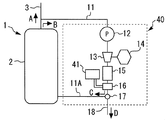
- FIG. 8 is a main part enlarged view showing a third modified example in which an ultrasonic shaking device is mounted on the water treatment device in the first embodiment of the present invention.
- the water treatment device 40 shown in this figure includes an ultrasonic shaking device 41 as a cleaning means.
- the ultrasonic shaking device 41 is controlled by a control device and has a function of causing the scale separation unit 16 to vibrate (ultrasonic shaking). Note that the strength of vibration generated by the ultrasonic shaking device 41 is determined by the constituent material, structure, strength, and the like of the scale separation unit 16.
- the control device activates the ultrasonic shaking device 41 to generate fine vibrations in the scale separation unit 16.
- the scale accumulated in the scale separation unit 16 is lifted from the wall surface of the scale separation unit 16 by being subjected to fine vibration, and is suspended in water. Since the floated scale is discharged to the return return pipe 6 through the flow path switching valve 17 and the drain pipe 18, the scale separator 16 can be washed.
- the water intake pump 12 is exemplified as means for introducing the water in the hot water storage tank 2 into the water treatment device 10.
- the present invention is not limited to this, and water may be introduced from the hot water storage tank 2 to the water treatment apparatus 10 by equipment other than the pump, or the water in the hot water storage tank 2 may be removed without using equipment such as a pump. It is good also as a structure which flows in into the water treatment apparatus 10 by natural fall.
- the intake pump 12 was arrange
- the drain pipe 18 is connected to the return pipe 6 and the waste water after the cleaning generated in the scale cleaning process is discharged to the return pipe 6.
- the waste water after washing can be caused to flow into the bathtub 9 from the return pipe 6, and the user or the like can easily treat the waste water simply by removing the waste water accumulated in the bathtub 9. it can. Therefore, the scale cleaning process can be efficiently performed using the existing piping mounted on the hot water supply apparatus 1, and the maintainability of the hot water supply apparatus 1 can be improved.
- the connection destination of the drain pipe 18 is not limited to the tracking return pipe 6.
- the drain pipe 18 may be connected to a pipe other than the return pipe 6 or may be configured to be connected to a dedicated waste water container, a waste water facility, or the like.
- the drain pipe 18 may be connected to, for example, the follow-up piping 5, and the same effect as when connected to the follow-up return pipe 6 can be obtained.
- the intake circuit 11 is shut off from the drain pipe 18 by the flow path switching valve 17, and the drain pipe 18 is held in a dead end state.
- the drain pipe 18 is held in a dead end state.
- the water treatment device 10 can efficiently remove scale components contained in the water handled by the hot water supply device 1.
- the scale is placed on the parts necessary for maintaining the function of the hot water supply device 1, that is, the hot water storage tank 2, the heat exchanger 4, the additional delivery pipe 5, the additional return pipe 6 and the like that are to be protected from the scale. It is possible to stably suppress adhesion and accumulation.
- the water quality is not acidified and the scale components are not kept in a water-soluble state, even when the water quality or the water temperature fluctuates, it is avoided that the scale is deposited at an unexpected part. Can do.
- the hot water supply apparatus 1 it is possible to suppress the performance and the hot water supply efficiency of the heat exchanger 4 from being deteriorated due to the scale adhering to the heat exchanger 4 or the like, and to stably exhibit the functions of the hot water supply apparatus 1. Can do.
- the configuration of the reaction tank 15A and the reaction channel 15B is illustrated as the scale reaction unit 15, and the configuration of the filter 16A, the heating type separator 16B, and the electrode reaction type separator 16C as the scale separation unit 16.
- the configurations of the bubble destruction device 21, the cleaning liquid supply device 31, and the ultrasonic shaking device 41 are illustrated.
- the present invention also includes a system that combines some of the configurations that can be combined, and a system that combines all the illustrated configurations.
- Embodiment 1 the case where the water treatment apparatus 10, 20, 30, 40 was applied to the hot water supply apparatus 1 was illustrated.
- the present invention is not limited to a hot water supply device, and can be applied to facilities equipped with various devices, piping, water tanks, and the like through which water containing scale components circulates.
- the present invention can be applied to facilities such as a heating apparatus and a washing machine including a floor heating system using hot water.
- 1 hot water supply device 2 hot water storage tank (equipment), 3 hot water supply piping, 4 heat exchanger, 5 additional delivery piping (external piping), 6 additional return piping (external piping), 7 additional pump, 8 hot water tap , 9 Bathtub, 10, 20, 30, 40 Water treatment device, 11 Intake pipe (intake circuit), 11A tank connection part, 12 Intake pump (intake circuit), 13 Gas supply part (cleaning means), 14 Gas container, 15 Scale reaction section, 15A reaction tank, 15B reaction flow path, 16 scale separation section, 16A filter, 16B heating type separator, 16C electrode reaction type separator, 17 flow path switching valve (drainage means), 18 drainage pipe (drainage means) ), 21 Bubble destruction device (bubble destruction means), 31 Cleaning liquid supply device (cleaning means), 41 Ultrasonic shaking device (cleaning means)
Landscapes
- Engineering & Computer Science (AREA)
- Chemical & Material Sciences (AREA)
- General Engineering & Computer Science (AREA)
- Mechanical Engineering (AREA)
- Physics & Mathematics (AREA)
- Thermal Sciences (AREA)
- Combustion & Propulsion (AREA)
- Life Sciences & Earth Sciences (AREA)
- Water Supply & Treatment (AREA)
- Organic Chemistry (AREA)
- Environmental & Geological Engineering (AREA)
- Hydrology & Water Resources (AREA)
- General Chemical & Material Sciences (AREA)
- Electrochemistry (AREA)
- Chemical Kinetics & Catalysis (AREA)
- Inorganic Chemistry (AREA)
- Heat-Pump Type And Storage Water Heaters (AREA)
- Details Of Fluid Heaters (AREA)
- Water Treatment By Electricity Or Magnetism (AREA)
Abstract
Priority Applications (3)
| Application Number | Priority Date | Filing Date | Title |
|---|---|---|---|
| EP13895133.0A EP3056473B1 (fr) | 2013-10-11 | 2013-10-11 | Dispositif de traitement d'eau et dispositif d'alimentation en eau chaude |
| PCT/JP2013/077796 WO2015052840A1 (fr) | 2013-10-11 | 2013-10-11 | Dispositif de traitement d'eau et dispositif d'alimentation en eau chaude |
| JP2015541408A JPWO2015052840A1 (ja) | 2013-10-11 | 2013-10-11 | 水処理装置、給湯装置及び暖房装置 |
Applications Claiming Priority (1)
| Application Number | Priority Date | Filing Date | Title |
|---|---|---|---|
| PCT/JP2013/077796 WO2015052840A1 (fr) | 2013-10-11 | 2013-10-11 | Dispositif de traitement d'eau et dispositif d'alimentation en eau chaude |
Publications (1)
| Publication Number | Publication Date |
|---|---|
| WO2015052840A1 true WO2015052840A1 (fr) | 2015-04-16 |
Family
ID=52812687
Family Applications (1)
| Application Number | Title | Priority Date | Filing Date |
|---|---|---|---|
| PCT/JP2013/077796 WO2015052840A1 (fr) | 2013-10-11 | 2013-10-11 | Dispositif de traitement d'eau et dispositif d'alimentation en eau chaude |
Country Status (3)
| Country | Link |
|---|---|
| EP (1) | EP3056473B1 (fr) |
| JP (1) | JPWO2015052840A1 (fr) |
| WO (1) | WO2015052840A1 (fr) |
Cited By (8)
| Publication number | Priority date | Publication date | Assignee | Title |
|---|---|---|---|---|
| WO2017138226A1 (fr) * | 2016-02-12 | 2017-08-17 | 三菱電機株式会社 | Système de canalisation de circulation et système de distribution d'eau contenant du dioxyde de carbone |
| CN110425923A (zh) * | 2019-08-19 | 2019-11-08 | 四川奥格莱能源科技有限公司 | 一种热交换器用双重连接装置 |
| CN113646267A (zh) * | 2019-03-27 | 2021-11-12 | 松下知识产权经营株式会社 | 离子除去系统 |
| CN113754120A (zh) * | 2021-09-14 | 2021-12-07 | 重庆华捷地热能开发有限公司 | 一种温泉井上负压强化析垢方法 |
| CN114206788A (zh) * | 2019-07-30 | 2022-03-18 | 松下知识产权经营株式会社 | 离子除去系统 |
| CN114857778A (zh) * | 2022-05-17 | 2022-08-05 | 广东固特科技有限公司 | 一种应用于热水器滤芯的超声波清理装置 |
| CN115014098A (zh) * | 2019-12-03 | 2022-09-06 | 山东大学 | 一种间歇协同振动智控的管壳式换热器 |
| JP7365618B2 (ja) | 2019-03-27 | 2023-10-20 | パナソニックIpマネジメント株式会社 | イオン除去システム |
Families Citing this family (6)
| Publication number | Priority date | Publication date | Assignee | Title |
|---|---|---|---|---|
| CN106839436B (zh) * | 2016-12-20 | 2019-08-02 | 石昌远 | 自清洗水箱及其在电热水器和太阳能热水器中的应用 |
| EP3712510B1 (fr) * | 2017-12-06 | 2022-04-27 | Mitsubishi Electric Corporation | Procédé de construction de dispositif de circulation d'eau et dispositif d'élimination de tartre |
| EP3760588B1 (fr) * | 2018-02-28 | 2023-10-18 | Panasonic Intellectual Property Management Co., Ltd. | Système d'élimination d'ions |
| US20220169542A1 (en) * | 2019-03-27 | 2022-06-02 | Panasonic Intellectual Property Management Co., Ltd. | Ion removal system |
| US20220169548A1 (en) * | 2019-03-27 | 2022-06-02 | Panasonic Intellectual Property Management Co., Ltd. | Ion removal system |
| CN111637519B (zh) * | 2019-05-27 | 2021-11-19 | 乌苏市鼎盛热力有限责任公司 | 一种公共场所地暖除垢装置 |
Citations (10)
| Publication number | Priority date | Publication date | Assignee | Title |
|---|---|---|---|---|
| JPS63302910A (ja) * | 1987-05-30 | 1988-12-09 | Nippon Atom Ind Group Co Ltd | 多孔質フィルタの洗浄方法 |
| JPH02187107A (ja) * | 1988-11-07 | 1990-07-23 | Framatome Et Cogema <Fragema> | 超音波清浄装置を備えた濾過装置および超音波清浄方法 |
| JPH09173804A (ja) * | 1995-10-26 | 1997-07-08 | Idec Izumi Corp | 気液溶解混合方法と装置 |
| JPH10174979A (ja) | 1996-12-18 | 1998-06-30 | Hitachi Zosen Corp | 排水処理方法および装置 |
| JP2001120918A (ja) * | 1999-10-29 | 2001-05-08 | Ebara Corp | 濾過面の洗浄方法及び固液分離装置 |
| JP3143158U (ja) * | 2008-04-28 | 2008-07-10 | 閔鍵 ▲登▼ | 気体液体混合装置 |
| JP2010078239A (ja) | 2008-09-26 | 2010-04-08 | Tokyo Electric Power Co Inc:The | 給湯装置およびスケール析出防止方法 |
| JP2010223525A (ja) | 2009-03-25 | 2010-10-07 | Osaka Gas Co Ltd | 熱交換器の配管内に付着したスケールの除去方法および除去装置 |
| JP2012523316A (ja) * | 2009-04-10 | 2012-10-04 | シルバン ソース, インコーポレイテッド | 水溶液の浄化におけるスケーリングを減らす方法およびシステム |
| JP2012251687A (ja) * | 2011-06-01 | 2012-12-20 | T Rad Co Ltd | 熱交換器システム |
Family Cites Families (2)
| Publication number | Priority date | Publication date | Assignee | Title |
|---|---|---|---|---|
| JP3143158B2 (ja) * | 1991-08-19 | 2001-03-07 | 三井化学株式会社 | ポリアミドの製造方法 |
| KR101163285B1 (ko) * | 2009-09-10 | 2012-07-05 | 손덕순 | 수중 칼슘?염소이온 제거장치 및 방법 |
-
2013
- 2013-10-11 JP JP2015541408A patent/JPWO2015052840A1/ja active Pending
- 2013-10-11 EP EP13895133.0A patent/EP3056473B1/fr active Active
- 2013-10-11 WO PCT/JP2013/077796 patent/WO2015052840A1/fr active Application Filing
Patent Citations (10)
| Publication number | Priority date | Publication date | Assignee | Title |
|---|---|---|---|---|
| JPS63302910A (ja) * | 1987-05-30 | 1988-12-09 | Nippon Atom Ind Group Co Ltd | 多孔質フィルタの洗浄方法 |
| JPH02187107A (ja) * | 1988-11-07 | 1990-07-23 | Framatome Et Cogema <Fragema> | 超音波清浄装置を備えた濾過装置および超音波清浄方法 |
| JPH09173804A (ja) * | 1995-10-26 | 1997-07-08 | Idec Izumi Corp | 気液溶解混合方法と装置 |
| JPH10174979A (ja) | 1996-12-18 | 1998-06-30 | Hitachi Zosen Corp | 排水処理方法および装置 |
| JP2001120918A (ja) * | 1999-10-29 | 2001-05-08 | Ebara Corp | 濾過面の洗浄方法及び固液分離装置 |
| JP3143158U (ja) * | 2008-04-28 | 2008-07-10 | 閔鍵 ▲登▼ | 気体液体混合装置 |
| JP2010078239A (ja) | 2008-09-26 | 2010-04-08 | Tokyo Electric Power Co Inc:The | 給湯装置およびスケール析出防止方法 |
| JP2010223525A (ja) | 2009-03-25 | 2010-10-07 | Osaka Gas Co Ltd | 熱交換器の配管内に付着したスケールの除去方法および除去装置 |
| JP2012523316A (ja) * | 2009-04-10 | 2012-10-04 | シルバン ソース, インコーポレイテッド | 水溶液の浄化におけるスケーリングを減らす方法およびシステム |
| JP2012251687A (ja) * | 2011-06-01 | 2012-12-20 | T Rad Co Ltd | 熱交換器システム |
Cited By (15)
| Publication number | Priority date | Publication date | Assignee | Title |
|---|---|---|---|---|
| JP6192881B1 (ja) * | 2016-02-12 | 2017-09-06 | 三菱電機株式会社 | 循環配管システム及び二酸化炭素含有水供給システム |
| EP3415836A4 (fr) * | 2016-02-12 | 2019-02-27 | Mitsubishi Electric Corporation | Système de canalisation de circulation et système de distribution d'eau contenant du dioxyde de carbone |
| WO2017138226A1 (fr) * | 2016-02-12 | 2017-08-17 | 三菱電機株式会社 | Système de canalisation de circulation et système de distribution d'eau contenant du dioxyde de carbone |
| JP7365617B2 (ja) | 2019-03-27 | 2023-10-20 | パナソニックIpマネジメント株式会社 | イオン除去システム |
| CN113646267A (zh) * | 2019-03-27 | 2021-11-12 | 松下知识产权经营株式会社 | 离子除去系统 |
| CN113646267B (zh) * | 2019-03-27 | 2024-03-08 | 松下知识产权经营株式会社 | 离子除去系统 |
| JP7365618B2 (ja) | 2019-03-27 | 2023-10-20 | パナソニックIpマネジメント株式会社 | イオン除去システム |
| CN114206788A (zh) * | 2019-07-30 | 2022-03-18 | 松下知识产权经营株式会社 | 离子除去系统 |
| CN114206788B (zh) * | 2019-07-30 | 2024-01-05 | 松下知识产权经营株式会社 | 离子除去系统 |
| CN110425923A (zh) * | 2019-08-19 | 2019-11-08 | 四川奥格莱能源科技有限公司 | 一种热交换器用双重连接装置 |
| CN115014098B (zh) * | 2019-12-03 | 2023-08-22 | 山东大学 | 一种间歇协同振动智控的管壳式换热器 |
| CN115014098A (zh) * | 2019-12-03 | 2022-09-06 | 山东大学 | 一种间歇协同振动智控的管壳式换热器 |
| CN113754120A (zh) * | 2021-09-14 | 2021-12-07 | 重庆华捷地热能开发有限公司 | 一种温泉井上负压强化析垢方法 |
| CN114857778B (zh) * | 2022-05-17 | 2023-08-15 | 广东固特科技有限公司 | 一种应用于热水器滤芯的超声波清理装置 |
| CN114857778A (zh) * | 2022-05-17 | 2022-08-05 | 广东固特科技有限公司 | 一种应用于热水器滤芯的超声波清理装置 |
Also Published As
| Publication number | Publication date |
|---|---|
| EP3056473A4 (fr) | 2017-03-15 |
| JPWO2015052840A1 (ja) | 2017-03-09 |
| EP3056473A1 (fr) | 2016-08-17 |
| EP3056473B1 (fr) | 2020-03-11 |
Similar Documents
| Publication | Publication Date | Title |
|---|---|---|
| WO2015052840A1 (fr) | Dispositif de traitement d'eau et dispositif d'alimentation en eau chaude | |
| JP2011056482A (ja) | 重金属汚染土壌の処理方法及び重金属汚染土壌の処理システム | |
| JP4508963B2 (ja) | 洗濯水処理装置および当該処理装置付洗濯機 | |
| JP4064969B2 (ja) | 室内載置型現像廃液処理装置並びに室内型現像廃液処理方法 | |
| KR102300297B1 (ko) | 플라즈마와 오존미세기포를 이용한 수처리장치 및 이를 이용한 수처리방법 | |
| JP2009090173A (ja) | 焼却灰の水洗処理方法及びシステム | |
| JP2009213961A (ja) | 空気洗浄器 | |
| WO2019167335A1 (fr) | Système d'élimination d'ions | |
| KR101392243B1 (ko) | 폐수 재활용장치를 구비한 악취처리시스템 | |
| JP2007330894A (ja) | 活性汚泥処理装置 | |
| JP7365618B2 (ja) | イオン除去システム | |
| JP6470939B2 (ja) | 排水の処理装置 | |
| JP2001269670A (ja) | 人工透析由来の廃液の中和処理装置 | |
| JP4577608B2 (ja) | 中和装置 | |
| JP5972155B2 (ja) | 廃水処理装置 | |
| JP2005185874A (ja) | 混濁汚水浄化装置 | |
| JP5393873B2 (ja) | スケール析出方法及び給湯器及びスケール析出装置 | |
| TW201134538A (en) | Coolant purification apparatus | |
| JP2008000725A (ja) | 油水分離装置 | |
| JP2005081237A (ja) | 汚泥減量化方法 | |
| CN209178206U (zh) | 一种新型农村一体化污水处理设备 | |
| JP2006198471A (ja) | 中和装置 | |
| JP2006122875A (ja) | 汚泥可溶化処理装置 | |
| JP5068773B2 (ja) | インジウム及び塩化第二鉄を含有するエッチング廃液からのインジウムの回収方法 | |
| CN208898669U (zh) | 一种污水处理高效电氧化气浮设备 |
Legal Events
| Date | Code | Title | Description |
|---|---|---|---|
| 121 | Ep: the epo has been informed by wipo that ep was designated in this application |
Ref document number: 13895133 Country of ref document: EP Kind code of ref document: A1 |
|
| ENP | Entry into the national phase |
Ref document number: 2015541408 Country of ref document: JP Kind code of ref document: A |
|
| NENP | Non-entry into the national phase |
Ref country code: DE |
|
| REEP | Request for entry into the european phase |
Ref document number: 2013895133 Country of ref document: EP |
|
| WWE | Wipo information: entry into national phase |
Ref document number: 2013895133 Country of ref document: EP |