実施の形態1.
以下、図1から図5を参照して、本発明の実施の形態1について説明する。なお、本明細書で使用する各図においては、共通する要素に同一の符号を付し、重複する説明を省略するものとする。図1は、本発明の実施の形態1による水処理装置を搭載した給湯装置を示す全体構成図である。
Embodiment 1 FIG.
Hereinafter, Embodiment 1 of the present invention will be described with reference to FIGS. In each drawing used in this specification, common elements are denoted by the same reference numerals, and redundant description is omitted. FIG. 1 is an overall configuration diagram showing a hot water supply apparatus equipped with a water treatment apparatus according to Embodiment 1 of the present invention.
図1に示すように、給湯装置1は、貯湯タンク2、給湯配管3等を備えている。貯湯タンク2は温水を貯湯するためのタンクであり、貯湯タンク2の上部側には、図示しない加熱装置により加熱された高温水が補充される。また、貯湯タンク2の下部側には、図示しない給水配管等を介して水源から低温水が補充されるように構成されている。これにより、貯湯タンク2には、上部側に高温水が滞留し、下部側に低温水が滞留するように温度成層が形成される。なお、貯湯タンク2は、水を取扱う設備に対応している。
As shown in FIG. 1, the hot water supply device 1 includes a hot water storage tank 2, a hot water supply pipe 3, and the like. The hot water storage tank 2 is a tank for storing hot water, and the upper side of the hot water storage tank 2 is supplemented with hot water heated by a heating device (not shown). Moreover, the lower side of the hot water storage tank 2 is configured to be supplemented with low-temperature water from a water source via a water supply pipe (not shown). Thereby, in the hot water storage tank 2, temperature stratification is formed so that high temperature water stays on the upper side and low temperature water stays on the lower side. The hot water storage tank 2 corresponds to a facility for handling water.
給湯配管3は、家屋の各所に配置された給湯栓8(1個のみ図示)に温水を供給するものである。給湯配管3の一端側は貯湯タンク2の上部に接続され、給湯配管3の他端側は給湯栓8に接続されている。また、給湯配管3には、貯湯タンク2の上部から取出した高温水に低温水を混合するための混合弁(図示せず)が接続されている。これにより、給湯栓8には、混合弁により適度な温度に調整された温水が給湯配管3を介して供給される。
The hot water supply pipe 3 supplies hot water to hot water taps 8 (only one is shown) arranged at various locations in the house. One end side of the hot water supply pipe 3 is connected to the upper part of the hot water storage tank 2, and the other end side of the hot water supply pipe 3 is connected to the hot water tap 8. The hot water supply pipe 3 is connected to a mixing valve (not shown) for mixing the low temperature water with the high temperature water taken out from the upper part of the hot water storage tank 2. Thus, hot water adjusted to an appropriate temperature by the mixing valve is supplied to the hot water tap 8 through the hot water supply pipe 3.
また、給湯装置1は、浴槽9に貯留された浴槽水を加熱(追焚き)するために、熱交換器4、追焚往き配管5、追焚戻し配管6、追焚ポンプ7等を備えている。熱交換器4は、貯湯タンク2に貯留された高温水または前記加熱装置により加熱された高温水を用いて浴槽水を加熱するもので、熱交換器4の1次側流路には、これらの高温水が供給されるように構成されている。熱交換器4の2次側流路は、追焚往き配管5及び追焚戻し配管6を介して浴槽9と接続されている。これにより、熱交換器4は、1次側流路に供給される高温水と2次側流路を流れる浴槽水との間で熱交換することにより、浴槽水を加熱する。
Further, the hot water supply device 1 includes a heat exchanger 4, a remedy outgoing pipe 5, a remedy return pipe 6, a remedy pump 7, and the like in order to heat (replace) the bathtub water stored in the bathtub 9. Yes. The heat exchanger 4 heats the bath water using the high-temperature water stored in the hot water storage tank 2 or the high-temperature water heated by the heating device. The high temperature water is configured to be supplied. The secondary-side flow path of the heat exchanger 4 is connected to the bathtub 9 via a tracking return pipe 5 and a tracking return pipe 6. Thereby, the heat exchanger 4 heats bathtub water by exchanging heat between the high temperature water supplied to a primary side flow path, and the bathtub water which flows through a secondary side flow path.
追焚往き配管5は、浴槽9から流出した浴槽水を熱交換器4の2次側流路に流入させるもので、追焚戻し配管6は、熱交換器4の2次側流路から流出した浴槽水を浴槽9に戻すものである。これらの追焚往き配管5及び追焚戻し配管6は、熱交換器4の2次側流路と浴槽9との間で浴槽水を循環させる追焚配管を構成している。追焚往き配管5には、上述した浴槽水の循環を行うための追焚ポンプ7が設けられている。なお、追焚ポンプ7は、追焚戻し配管6に設けてもよい。
The follow-up piping 5 allows the bath water flowing out from the bathtub 9 to flow into the secondary flow path of the heat exchanger 4, and the tracking return pipe 6 flows out from the secondary flow path of the heat exchanger 4. The bathtub water thus returned is returned to the bathtub 9. These retrace piping 5 and retreat return piping 6 constitute regenerative piping that circulates bathtub water between the secondary flow path of the heat exchanger 4 and the bathtub 9. The remedy piping 5 is provided with a remedy pump 7 for circulating the bath water described above. The remedy pump 7 may be provided in the remedy return pipe 6.
次に、給湯装置1の基本的な動作について説明する。まず、ユーザが給湯栓8を操作したときには、貯湯タンク2の上部に貯留された高温水が給湯配管3に流出し、この高温水には、混合弁により低温水が混合される。このとき、混合弁による高温水と低温水との混合比率は、給湯装置1に搭載された制御装置(図示せず)等により制御される。これにより、給湯配管3を流れる温水の温度は、例えばユーザが予め設定しておいた給湯温度となるように調整され、この温水は給湯配管3から給湯栓8に供給される。
Next, the basic operation of the water heater 1 will be described. First, when the user operates the hot water tap 8, the high temperature water stored in the upper part of the hot water storage tank 2 flows out into the hot water supply pipe 3, and the high temperature water is mixed with low temperature water by the mixing valve. At this time, the mixing ratio of the high temperature water and the low temperature water by the mixing valve is controlled by a control device (not shown) or the like mounted on the hot water supply device 1. Thereby, the temperature of the hot water flowing through the hot water supply pipe 3 is adjusted to be, for example, a hot water supply temperature preset by the user, and this hot water is supplied from the hot water supply pipe 3 to the hot water tap 8.
また、ユーザにより浴槽水の追焚き操作が行われたときには、制御装置により追焚運転が実行される。この場合、制御装置は、追焚ポンプ7を駆動すると共に、熱交換器4の1次側流路に高温水を供給する。これにより、熱交換器4の2次側流路を循環する浴槽水は、熱交換器4により加熱された後に浴槽9に戻されるようになり、浴槽9内の浴槽水が加熱される。一方、上述した給湯動作や追焚運転により貯湯タンク2の高温水が減少すると、制御装置により沸上げ運転が実行される。沸上げ運転では、貯湯タンク2の下部側から取出した低温水を前記加熱装置により加熱し、これによって生成した高温水を貯湯タンク2の上部に戻すことにより、貯湯タンク2内の水を加熱する。
In addition, when the user performs a bath water purging operation, the control device performs a chasing operation. In this case, the control device drives the remedy pump 7 and supplies hot water to the primary flow path of the heat exchanger 4. Thereby, the bathtub water circulating through the secondary side flow path of the heat exchanger 4 comes back to the bathtub 9 after being heated by the heat exchanger 4, and the bathtub water in the bathtub 9 is heated. On the other hand, when the hot water in the hot water storage tank 2 is reduced by the hot water supply operation and the chasing operation described above, the controller performs a boiling operation. In the boiling operation, the low temperature water taken out from the lower side of the hot water storage tank 2 is heated by the heating device, and the hot water generated thereby is returned to the upper part of the hot water storage tank 2 to heat the water in the hot water storage tank 2. .
次に、図1及び図2を参照して、給湯装置1に備えられた水処理装置10について説明する。図2は、図1中の水処理装置を拡大して示す要部拡大図である。水処理装置10は、貯湯タンク2に貯留された温水中のスケール成分を除去するものである。なお、以下の説明において、スケール成分とは、水中に溶け込んだカルシウムイオン、マグネシウムイオン等の硬度成分を意味し、スケールとは、これらの硬度成分の炭酸化合物である炭酸カルシウム、炭酸マグネシウム等を意味している。
Next, with reference to FIG.1 and FIG.2, the water treatment apparatus 10 with which the hot water supply apparatus 1 was equipped is demonstrated. FIG. 2 is an enlarged view of a main part showing the water treatment apparatus in FIG. 1 in an enlarged manner. The water treatment device 10 removes scale components from the hot water stored in the hot water storage tank 2. In the following description, the scale component means a hardness component such as calcium ion or magnesium ion dissolved in water, and the scale means calcium carbonate, magnesium carbonate or the like which is a carbonate compound of these hardness components. is doing.
給湯装置1においては、特に井水等のスケール成分の含有量が多い水を給湯水として用いる場合に、貯湯タンク2の内壁面等にスケールが析出して付着し易い。また、高温水が流通する給湯配管3、熱交換器4、追焚往き配管5、追焚戻し配管6等の内部にも、スケールが付着し易い。水処理装置10は、このように給湯装置1の機能を維持するために必要な設備、即ち、スケールから保護したい設備に対してスケールが付着するのを抑制するものである。水処理装置10は、図1及び図2に示すように、取水配管11、取水ポンプ12、ガス供給部13、ガス容器14、スケール反応部15、スケール分離部16、流路切換弁17、排水配管18等を備えている。
In the hot water supply device 1, scale is likely to deposit and adhere to the inner wall surface of the hot water storage tank 2, particularly when water having a large content of scale components such as well water is used as hot water. In addition, the scale easily adheres to the inside of the hot water supply pipe 3 through which the high-temperature water circulates, the heat exchanger 4, the follow-up outgoing pipe 5, the extra return pipe 6, and the like. The water treatment apparatus 10 suppresses the scale from adhering to the equipment necessary for maintaining the function of the hot water supply apparatus 1 as described above, that is, the equipment to be protected from the scale. As shown in FIGS. 1 and 2, the water treatment apparatus 10 includes a water intake pipe 11, a water intake pump 12, a gas supply unit 13, a gas container 14, a scale reaction unit 15, a scale separation unit 16, a flow path switching valve 17, a drainage A pipe 18 and the like are provided.
取水配管11は、取水ポンプ12と共に貯湯タンク2から水を取出して当該水を貯湯タンク2に戻す取水回路を構成している。取水ポンプ12は、貯湯タンク2に貯留された温水を取水配管11に循環させるものである。取水配管11の一端側(上流側)は、貯湯タンク2の上部に接続されている。なお、図1及び図2では、取水配管11の上流側を給湯配管3を介して貯湯タンク2の上部に接続した場合を例示したが、取水配管11の上流側を貯湯タンク2の上部に直接接続する構成としてもよい。
The intake pipe 11 constitutes an intake circuit that takes out water from the hot water storage tank 2 together with the intake pump 12 and returns the water to the hot water storage tank 2. The water intake pump 12 circulates the hot water stored in the hot water storage tank 2 through the water pipe 11. One end side (upstream side) of the intake pipe 11 is connected to the upper part of the hot water storage tank 2. 1 and 2 exemplify the case where the upstream side of the intake pipe 11 is connected to the upper part of the hot water storage tank 2 via the hot water supply pipe 3, the upstream side of the intake water pipe 11 is directly connected to the upper part of the hot water storage tank 2. It is good also as a structure to connect.
取水配管11の他端側(下流側)は、貯湯タンク2の下部側に接続されている。以下の説明では、取水配管11のうち流路切換弁17よりも下流側に位置する部位を、タンク接続部11Aと表記する。即ち、タンク接続部11Aは、流路切換弁17と貯湯タンク2の下部側とを接続している。なお、タンク接続部11Aは、給湯装置1に搭載された他の配管を介して貯湯タンク2の下部側に接続してもよい。取水配管11には、水の流れ方向に沿って上流側から順番に、取水ポンプ12、ガス供給部13、スケール反応部15、スケール分離部16、流路切換弁17が設けられている。
The other end side (downstream side) of the intake pipe 11 is connected to the lower side of the hot water storage tank 2. In the following description, a portion of the intake pipe 11 that is located downstream of the flow path switching valve 17 is referred to as a tank connection portion 11A. That is, the tank connecting portion 11 </ b> A connects the flow path switching valve 17 and the lower side of the hot water storage tank 2. Note that the tank connection portion 11 </ b> A may be connected to the lower side of the hot water storage tank 2 via another pipe mounted on the hot water supply device 1. The intake pipe 11 is provided with an intake pump 12, a gas supply unit 13, a scale reaction unit 15, a scale separation unit 16, and a flow path switching valve 17 in order from the upstream side along the water flow direction.
ガス供給部13は、例えば二酸化炭素を含むガスが貯蔵されたガス容器14に接続されており、取水配管11を流れる水に対してガス容器14内のガスを供給するものである。なお、以下の説明において、「ガス」とは、二酸化炭素を含むガスを意味するものとする。ガス供給部13は、ガスを微細気泡化する微細気泡発生装置(図示せず)を備えている。ガス供給部13から供給されるガスは、微細気泡発生装置により、例えば直径10μm以下、好ましくは直径1μm以下の微細な気泡にされた状態で水中に混入される。特に、直径1μm以下の微細気泡を形成した場合には、水中で気泡同士が合体して気泡が大型化する合泡等が発生し難くなり、スケール成分と反応し易い微細気泡を安定的に維持することができる。なお、ガス供給部13により供給するガスは、二酸化炭素が元々含まれている大気でもよいし、二酸化炭素の濃度を大気中よりも高くした高濃度のガスでもよい。
The gas supply unit 13 is connected to, for example, a gas container 14 in which a gas containing carbon dioxide is stored, and supplies the gas in the gas container 14 to the water flowing through the intake pipe 11. In the following description, “gas” means a gas containing carbon dioxide. The gas supply unit 13 includes a fine bubble generator (not shown) that makes gas fine bubbles. The gas supplied from the gas supply unit 13 is mixed into water by the fine bubble generator in the form of fine bubbles having a diameter of 10 μm or less, preferably 1 μm or less, for example. In particular, when microbubbles with a diameter of 1 μm or less are formed, it is difficult for bubbles to coalesce in water and the bubbles become large, and stable maintenance of microbubbles that easily react with scale components. can do. The gas supplied by the gas supply unit 13 may be air that originally contains carbon dioxide, or may be high-concentration gas in which the concentration of carbon dioxide is higher than that in the air.
ガス供給部13により二酸化炭素を微細化するための具体的な手段としては、例えば高圧下でガスを水中に溶解させた後に、減圧により水中のガスを気泡化する加圧減圧法を用いてもよい。また、水の旋回流を形成し、この旋回流中にガスを巻き込ませることにより当該ガスをせん断または粉砕して気泡化する気液せん断法を用いてもよい。気液せん断法では、例えば翼等の構造物により水を400回/分以上の高速で旋回させ、二酸化炭素を含むガスを旋回流の中に吸引しつつ、このガスを切断または粉砕して微細気泡を生成する。
As a specific means for refining carbon dioxide by the gas supply unit 13, for example, a pressure / decompression method in which gas is dissolved in water under high pressure and then the gas in water is bubbled by decompression may be used. Good. Alternatively, a gas-liquid shearing method may be used in which a swirl flow of water is formed and gas is entrained in the swirl flow to shear or pulverize the gas to form bubbles. In the gas-liquid shearing method, for example, water is swirled at a high speed of 400 times / minute or more by a structure such as a wing, and the gas containing carbon dioxide is sucked into the swirling flow, and this gas is cut or pulverized to obtain fine particles. Generate bubbles.
スケール反応部15は、ガス供給部13により水中に供給されたガスの微細気泡と、取水配管11を流れる水中のスケール成分とを反応させる部位であり、水中にスケールの微粒子を効率よく析出させることができる。スケール反応部15は、ガス供給部13とスケール分離部16との間に配置されている。図3は、本発明の実施の形態1によるスケール反応部の具体例(a),(b)を示す斜視図である。まず、図3(a)は、スケール反応部15の一例である反応槽15Aを示している。反応槽15Aは、例えば円筒状の容器により形成され、その軸方向の端面には、取水配管11の上流側、下流側にそれぞれ接続される接続口15a,15bが設けられている。
The scale reaction unit 15 is a part that reacts the fine gas bubbles supplied into the water by the gas supply unit 13 with the scale components in the water flowing through the intake pipe 11, and efficiently deposits the fine particles of the scale in the water. Can do. The scale reaction unit 15 is disposed between the gas supply unit 13 and the scale separation unit 16. FIG. 3 is a perspective view showing specific examples (a) and (b) of the scale reaction unit according to the first embodiment of the present invention. First, FIG. 3A shows a reaction tank 15 </ b> A that is an example of the scale reaction unit 15. The reaction tank 15A is formed of, for example, a cylindrical container, and connection ports 15a and 15b connected to the upstream side and the downstream side of the water intake pipe 11 are provided on the axial end surface thereof.
反応槽15Aは、取水配管11に接続した状態において、取水配管11の途中部位を拡径した状態となるような形状を有している。即ち、反応槽15Aは、取水配管11の径方向において、取水配管11の流路よりも大きな寸法をもって形成されている。これにより、反応槽15Aによれば、取水配管11を流れる水とガスとの混合物をスケール分離部16の上流側で一時的に貯留し、水と二酸化炭素との反応によるスケールの析出を促進することができる。
The reaction tank 15 </ b> A has such a shape that, when connected to the intake pipe 11, the diameter of an intermediate portion of the intake pipe 11 is expanded. That is, the reaction tank 15 </ b> A is formed with a size larger than the flow path of the intake pipe 11 in the radial direction of the intake pipe 11. Thereby, according to the reaction tank 15A, the mixture of water and gas flowing through the intake pipe 11 is temporarily stored on the upstream side of the scale separation unit 16, and the precipitation of scale due to the reaction between water and carbon dioxide is promoted. be able to.
なお、一定量の水とガスとを反応槽15A内に一旦閉じ込めた状態でスケールの析出を進行させる処理(所謂バッチ式の処理)を行う場合には、接続口15a,15bに電磁弁等の遮断弁を設けて水流を一時的に停止させる構成としてもよい。また、反応槽15Aの容積は、貯湯タンク2よりも小さくするのが好ましい。何故なら、反応槽15Aの水処理量を貯湯タンク2以上としても無意味である上に、反応槽15Aの容積が小さいほど、その内部に滞留する二酸化炭素の微細気泡の数が増えてスケールの析出反応が促進されるからである。
In addition, when performing a process (so-called batch-type process) in which a predetermined amount of water and gas is once confined in the reaction tank 15A to advance the precipitation of the scale (so-called batch type process), an electromagnetic valve or the like is connected to the connection ports 15a and 15b. It is good also as a structure which provides a cutoff valve and stops a water flow temporarily. The volume of the reaction tank 15A is preferably smaller than that of the hot water storage tank 2. This is because it is meaningless even if the water treatment amount of the reaction tank 15A is more than the hot water storage tank 2, and the smaller the volume of the reaction tank 15A, the larger the number of fine bubbles of carbon dioxide staying in the reaction tank 15A. This is because the precipitation reaction is promoted.
一方、図3(b)は、スケール反応部15の一例である反応流路15Bを示している。反応流路15Bは、螺旋状に湾曲した流路として形成され、当該流路の端部側には、取水配管11の上流側、下流側にそれぞれ接続される接続口15c,15dが設けられている。反応流路15Bの流路径は、析出したスケールによって流路が閉塞しない太さに設計する必要がある。反応流路15Bによれば、スケール反応部15としての容積がコンパクトであっても、水と二酸化炭素とが混ざり合いながら流れる反応時間を長く確保することができ、スケールの析出を促進することができる。
On the other hand, FIG. 3 (b) shows a reaction channel 15 </ b> B that is an example of the scale reaction unit 15. The reaction channel 15B is formed as a spirally curved channel, and connection ports 15c and 15d connected to the upstream side and the downstream side of the intake pipe 11 are provided on the end side of the channel. Yes. The diameter of the reaction channel 15B needs to be designed so that the channel is not blocked by the deposited scale. According to the reaction flow path 15B, even if the volume as the scale reaction section 15 is compact, it is possible to ensure a long reaction time while water and carbon dioxide are mixed, and promote precipitation of scale. it can.
なお、本発明は、必ずしもスケール反応部15を必要とするものではない。一例を挙げると、取水配管11によりガス供給部13とスケール分離部16との間に十分な長さの流路を確保できるのであれば、この流路自体がスケール反応部となるので、スケール反応部となる専用の部品を用いる必要はない。また、本発明では、スケール反応部15として、反応槽15Aと反応流路15Bとを接続したものを用いてもよい。また、水中で析出したスケールはスケール反応部15に蓄積易いので、スケール反応部15の近傍には、熱源等を配置しないようにして、スケールが析出し過ぎる状況を回避するのが好ましい。但し、設計上の制約等から、スケール反応部15を熱源の近くに配置する場合には、ガス供給部13による二酸化炭素の供給量を調整したり、後述のスケール洗浄処理を頻繁に実行する等の対策を行うのが好ましい。
The present invention does not necessarily require the scale reaction unit 15. For example, if a sufficiently long channel can be secured between the gas supply unit 13 and the scale separation unit 16 by the intake pipe 11, the channel itself becomes a scale reaction unit. There is no need to use a dedicated part. In the present invention, the scale reaction unit 15 may be one in which a reaction tank 15A and a reaction channel 15B are connected. In addition, since the scale deposited in water is likely to accumulate in the scale reaction unit 15, it is preferable not to place a heat source or the like in the vicinity of the scale reaction unit 15 to avoid a situation in which the scale is excessively precipitated. However, when the scale reaction unit 15 is disposed near the heat source due to design restrictions, the amount of carbon dioxide supplied by the gas supply unit 13 is adjusted, scale cleaning processing described later is frequently executed, etc. It is preferable to take the above measures.
スケール分離部16は、ガス供給部13の下流側での反応、特にスケール反応部15での反応により水中に析出したスケールの微粒子を大きな粒子に成長させ、この粒子を水中から分離及び除去するものである。スケール分離部16は、ガス供給部13の下流側で取水配管11に設けられている。図4は、本発明の実施の形態1によるスケール分離部の具体例(a),(b),(c)を示す斜視図である。
The scale separation unit 16 grows scale fine particles precipitated in water by the reaction on the downstream side of the gas supply unit 13, particularly the reaction in the scale reaction unit 15, and separates and removes the particles from the water. It is. The scale separation unit 16 is provided in the intake pipe 11 on the downstream side of the gas supply unit 13. FIG. 4 is a perspective view showing specific examples (a), (b), and (c) of the scale separation unit according to the first embodiment of the present invention.
まず、図4(a)に示すフィルタ16Aは、フィルタ状の構造を有し、水中に含まれるスケールの粒子を濾過して分離する。また、図4(b)に示す加熱型分離器16Bは、取水配管11に接続される流路16aと、この流路16aを取囲むように配置されて流路16a内を流れる水を加熱する環状のヒータ16bとを備えている。そして、加熱型分離器16Bは、水温が高いほどスケール成分の溶解度が減少する特性を利用して、ヒータ16bが水を加熱することによりスケールの析出を促進するものである。
First, the filter 16A shown in FIG. 4 (a) has a filter-like structure, and filters and separates particles of scale contained in water. Moreover, the heating type separator 16B shown in FIG.4 (b) heats the water which flows through the flow path 16a arrange | positioned so that the flow path 16a connected to the intake pipe 11 and this flow path 16a may be surrounded. And an annular heater 16b. The heating separator 16B uses the characteristic that the solubility of the scale component decreases as the water temperature increases, and the heater 16b heats the water to promote the precipitation of the scale.
また、図4(c)に示す電極反応型分離器16Cは、例えば一対の電極16c,16dを備え、これらの電極16c,16d間に電圧を印加することにより、スケールの析出を促進するものである。一般に、炭酸カルシウム等のスケールは、アルカリ性の溶液中で析出が促進される。従って、電極反応型分離器16Cでは、例えば電圧の極性を図示のように設定することにより、陰極となる電極16dの周囲にアルカリ性領域を形成し、この領域でスケールの析出を促進することができる。
Moreover, the electrode reaction type | mold separator 16C shown in FIG.4 (c) is provided with a pair of electrodes 16c and 16d, for example, and accelerates | stimulates precipitation of a scale by applying a voltage between these electrodes 16c and 16d. is there. In general, precipitation of a scale such as calcium carbonate is promoted in an alkaline solution. Therefore, in the electrode reaction type separator 16C, for example, by setting the polarity of the voltage as shown in the figure, an alkaline region can be formed around the electrode 16d serving as the cathode, and scale deposition can be promoted in this region. .
なお、図4では、スケール分離部16として、フィルタ16A、加熱型分離器16B及び電極反応型分離器16Cからなる3種類の機器を例示したが、本発明では、これら3種類の機器のうちの2つまたは3つの機器を組合わせて1つのスケール分離部16を構成してもよい。そして、この場合には、組合わせる機器の最下流側に、スケールの分離能力が高いフィルタ16Aを配置するのが好ましい。また、本発明では、スケール分離部16の外郭を、例えば反応槽15Aと同様の大径な水槽により構成してもよい。
In FIG. 4, three types of devices including the filter 16 </ b> A, the heating type separator 16 </ b> B, and the electrode reaction type separator 16 </ b> C are illustrated as the scale separation unit 16. In the present invention, among these three types of devices, One scale separation unit 16 may be configured by combining two or three devices. In this case, it is preferable to arrange the filter 16A having a high scale separation capability on the most downstream side of the device to be combined. Moreover, in this invention, you may comprise the outline of the scale separation part 16 with the large diameter water tank similar to 15 A of reaction tanks, for example.
また、図4(c)に示す電極反応型分離器16Cでは、水の流路内に2個の電極16c,16dを配置する場合を例示した。しかし、本発明はこれに限らず、例えば円筒状をなす流路の中心に陽極となる電極を配置し、流路の周壁により陰極側の電極を構成してもよい。また、中心と周壁のどちらを陽極とするべきかについては、特に指定しなくてもよいが、陰極の周囲にアルカリ性領域が形成されてスケールが析出するので、面積がより大きい周壁を陰極とするのが好ましい。さらに、スケール分離部16は、バッチ式の処理が可能な構成としてもよい。バッチ式の処理では、スケールを含む一定量の水をスケール分離部16内に一旦閉じ込め、この状態でスケールの分離及び除去を進行させる。
Moreover, in the electrode reaction type separator 16C shown in FIG. 4C, the case where two electrodes 16c and 16d are arranged in the flow path of water is illustrated. However, the present invention is not limited to this. For example, an electrode serving as an anode may be disposed at the center of a cylindrical flow path, and the cathode-side electrode may be configured by the peripheral wall of the flow path. In addition, there is no need to specify whether the center or the peripheral wall should be the anode, but since an alkaline region is formed around the cathode and the scale is deposited, the peripheral wall having a larger area is used as the cathode. Is preferred. Furthermore, the scale separation unit 16 may be configured to be capable of batch processing. In the batch process, a certain amount of water including the scale is once confined in the scale separation unit 16, and separation and removal of the scale are advanced in this state.
次に、図1及び図2を参照して、本実施の形態の排水手段を構成する流路切換弁17及び排水配管18について説明する。排水手段は、後述のスケール洗浄処理を実行したときに、スケール分離部16から流出した水を貯湯タンク2に戻さずに外部に排出するもので、本実施の形態では、水の排出先として追焚戻し配管6を例示している。
Next, with reference to FIGS. 1 and 2, the flow path switching valve 17 and the drainage pipe 18 constituting the drainage means of the present embodiment will be described. The drainage means discharges the water that has flowed out of the scale separation unit 16 to the outside without returning it to the hot water storage tank 2 when the scale cleaning process described later is executed. An example of the return pipe 6 is shown.
流路切換弁17は、スケール分離部16から流出した水の流路をタンク接続部11Aと排水配管18の何れかに切換えるものである。流路切換弁17は、電磁駆動式の三方弁等により構成され、1つの流入ポートと2つの流出ポートとを有している。流路切換弁17の流入ポートは、スケール分離部16の下流側で取水配管11に接続されている。また、2つの流出ポートのうち一方の流出ポートは、取水配管11のタンク接続部11Aを介して貯湯タンク2の下部側に接続され、他方の流出ポートは、排水配管18を介して追焚戻し配管6に接続されている。
The flow path switching valve 17 switches the flow path of the water flowing out from the scale separation section 16 to either the tank connection section 11A or the drain pipe 18. The flow path switching valve 17 is constituted by an electromagnetically driven three-way valve or the like, and has one inflow port and two outflow ports. The inflow port of the flow path switching valve 17 is connected to the intake pipe 11 on the downstream side of the scale separation unit 16. In addition, one outflow port of the two outflow ports is connected to the lower side of the hot water storage tank 2 via the tank connection portion 11A of the intake pipe 11, and the other outflow port is retraced via the drainage pipe 18. It is connected to the pipe 6.
このように構成される水処理装置10は、例えば給湯装置1の制御装置により制御される。即ち、給湯装置1の制御装置は、水処理装置10の取水ポンプ12、ガス供給部13、流路切換弁17等を制御するように構成されている。なお、本発明では、給湯装置1と水処理装置10の制御装置を必ずしも兼用する必要はなく、水処理装置10を制御する専用の制御装置を搭載してもよい。
The water treatment device 10 configured as described above is controlled by, for example, a control device of the hot water supply device 1. That is, the control device of the hot water supply device 1 is configured to control the water intake pump 12, the gas supply unit 13, the flow path switching valve 17 and the like of the water treatment device 10. In the present invention, the hot water supply device 1 and the control device for the water treatment device 10 do not necessarily have to be combined, and a dedicated control device for controlling the water treatment device 10 may be mounted.
(スケール除去処理)
次に、本実施の形態による水処理装置10の作動について説明する。まず、水処理装置10は、貯湯タンク2内の水に含まれるスケール成分を除去するスケール除去処理を実行することができる。スケール除去処理では、図2において、流路切換弁17により取水配管11の下流側を貯湯タンク2と接続し、この状態で取水ポンプ12及びガス供給部13を駆動する。このとき、排水配管18は、流路切換弁17により取水配管11から遮断されている。取水ポンプ12が作動すると、貯湯タンク2の上部から温水が取出され、この温水は、給湯時のように矢示A方向には流れず、矢示B方向に流れて取水配管11を流通する。そして、この温水は、流路切換弁17を介して矢示C方向に流通し、貯湯タンク2に戻されるようになり、取水配管11を循環する。
(Scale removal processing)
Next, the operation of the water treatment apparatus 10 according to this embodiment will be described. First, the water treatment device 10 can execute a scale removal process for removing scale components contained in the water in the hot water storage tank 2. In the scale removal process, the downstream side of the intake pipe 11 is connected to the hot water storage tank 2 by the flow path switching valve 17 in FIG. 2, and the intake pump 12 and the gas supply unit 13 are driven in this state. At this time, the drain pipe 18 is blocked from the intake pipe 11 by the flow path switching valve 17. When the water intake pump 12 is operated, hot water is taken out from the upper part of the hot water storage tank 2, and this hot water flows in the direction indicated by the arrow B and flows through the water intake piping 11 as in the hot water supply. Then, this hot water flows in the direction indicated by the arrow C via the flow path switching valve 17 and is returned to the hot water storage tank 2 and circulates through the water intake pipe 11.
また、取水配管11を循環する水には、まず、ガス供給部13から水中に二酸化炭素を含むガスの微細気泡が混入され、この微細気泡を含む水はスケール反応部15を流通する。これにより、スケール反応部15を含む流路では、下記化1の反応式に示すように、水中のスケール成分と二酸化炭素との反応が進行してスケールの微粒子が析出し、析出した微粒子は成長して大型化する。そして、このスケール粒子は、スケール分離部16に到達し、スケール分離部16により水中から除去される。なお、下記の反応式は、スケール成分としてカルシウムイオンを例示したものである。
Also, in the water circulating through the intake pipe 11, first, fine bubbles of gas containing carbon dioxide are mixed into the water from the gas supply unit 13, and the water containing these fine bubbles flows through the scale reaction unit 15. As a result, in the flow path including the scale reaction section 15, the reaction between the scale component in water and carbon dioxide proceeds as shown in the reaction formula of the following chemical formula 1, and the fine particles of the scale are deposited. And increase in size. The scale particles reach the scale separator 16 and are removed from the water by the scale separator 16. In addition, the following reaction formula illustrates calcium ion as a scale component.
具体例を挙げると、スケール分離部16がフィルタ16Aである場合には、水中のスケール粒子を濾過により除去することができる。また、スケール分離部16が加熱型分離器16Bまたは電極反応型分離器16Cである場合には、スケール分離部16において、水が加熱された領域またはアルカリ性の領域が存在するので、スケール粒子は、これらの領域で更に大きな粒子に成長する。従って、沈殿、濾過等の手段によりスケールを容易に除去することができる。
As a specific example, when the scale separator 16 is the filter 16A, scale particles in water can be removed by filtration. In addition, when the scale separator 16 is the heating separator 16B or the electrode reaction separator 16C, the scale separator 16 has a region where water is heated or an alkaline region. Grows into larger particles in these areas. Accordingly, the scale can be easily removed by means such as precipitation and filtration.
特に、スケール分離部16が加熱型分離器16Bである場合には、水温の上昇に伴って物質(元素、原子、分子)が高エネルギ状態となり、物質同士の衝突確率、つまり反応頻度が高くなる。従って、水中のイオンであるスケール成分から炭酸化合物が生成される反応を効率よく進行させることができる。このような観点から、本発明では、スケール分離部16として加熱型分離器16Bを用いる場合に、スケール反応部15と加熱型分離器16Bとを同一の機器として一体化し、例えば反応槽15A及び反応流路15Bの周壁を加熱する構成としてもよい。また、本発明では、例えばスケール反応部15と電極反応型分離器16Cとを同一の機器として一体化し、例えば反応槽15A及び反応流路15Bの内部に電極16c,16dを配置する構成としてもよい。
In particular, when the scale separator 16 is the heating separator 16B, the substance (element, atom, molecule) becomes in a high energy state as the water temperature rises, and the collision probability between substances, that is, the reaction frequency increases. . Therefore, the reaction in which a carbonate compound is generated from a scale component that is an ion in water can be efficiently advanced. From such a viewpoint, in the present invention, when the heating type separator 16B is used as the scale separation unit 16, the scale reaction unit 15 and the heating type separator 16B are integrated as the same device, for example, the reaction tank 15A and the reaction It is good also as a structure which heats the surrounding wall of the flow path 15B. Further, in the present invention, for example, the scale reaction unit 15 and the electrode reaction type separator 16C may be integrated as the same device, and the electrodes 16c and 16d may be disposed inside the reaction tank 15A and the reaction channel 15B, for example. .
このようにして、スケール分離部16により軟水化された水は、流路切換弁17に到達し、取水配管11のタンク接続部11Aを経由して貯湯タンク2の下部側に戻される。このとき、スケール分離部16には、水から分離されたスケールが蓄積される。従って、スケール除去処理によれば、貯湯タンク2内の水からスケール成分を除去することができる。なお、後述のスケール洗浄処理を行う場合には、スケール分離部16から流出した水が流路切換弁17を介して排水配管18に流入し、貯湯タンク2に水が戻されなくなる。
Thus, the water softened by the scale separation unit 16 reaches the flow path switching valve 17 and is returned to the lower side of the hot water storage tank 2 via the tank connection portion 11A of the intake pipe 11. At this time, the scale separated from the water is accumulated in the scale separation unit 16. Therefore, according to the scale removal process, the scale component can be removed from the water in the hot water storage tank 2. In addition, when performing the scale washing process described later, the water flowing out from the scale separation unit 16 flows into the drain pipe 18 through the flow path switching valve 17 and the water is not returned to the hot water storage tank 2.
上述したスケール除去処理では、例えばガス供給部13から供給する二酸化炭素ガスの温度を上昇させることにより、スケール反応部15でのスケールの反応効率を高める方法が有効である。炭酸カルシウム等のスケールは、温度が高いほど析出し易い傾向があるので、供給するガスの温度を高くすれば、反応効率を向上させることができる。具体例を挙げると、ガス容器14からガス供給部13に至るガスの流路に、ガスを加熱するヒータを設けてもよい。
In the scale removal process described above, for example, a method of increasing the scale reaction efficiency in the scale reaction unit 15 by increasing the temperature of carbon dioxide gas supplied from the gas supply unit 13 is effective. Since scales such as calcium carbonate tend to precipitate as the temperature increases, the reaction efficiency can be improved by increasing the temperature of the supplied gas. As a specific example, a heater for heating the gas may be provided in the gas flow path from the gas container 14 to the gas supply unit 13.
また、水処理装置10を給湯装置1に適用する場合には、貯湯タンク2内の温水から熱が伝導する位置、好ましくは貯湯タンク2の上部近傍にガス供給部13またはガス容器14を配置する構成としてもよい。この構成によれば、専用のヒータ等を用いなくても、貯湯タンク2の熱を利用して二酸化炭素ガスを効率よく加熱し、スケールの反応効率を高めることができる。また、スケール反応部15にヒータを設けたり、スケール反応部15を貯湯タンク2の上部近傍に配置することで、貯湯タンク2の熱を利用して取水配管11内の水温を上昇させる構成としてもよい。これらの方法によれば、ヒータ等からなる専用の加熱手段を用いなくても、取水配管11内の水温または二酸化炭素ガスの温度を効率よく上昇させ、スケールの反応効率を高めることができる。
When the water treatment device 10 is applied to the hot water supply device 1, the gas supply unit 13 or the gas container 14 is disposed at a position where heat is conducted from the hot water in the hot water storage tank 2, preferably in the vicinity of the upper portion of the hot water storage tank 2. It is good also as a structure. According to this configuration, the carbon dioxide gas can be efficiently heated using the heat of the hot water storage tank 2 without using a dedicated heater or the like, and the reaction efficiency of the scale can be increased. In addition, the scale reaction unit 15 may be provided with a heater, or the scale reaction unit 15 may be disposed near the upper portion of the hot water storage tank 2 to increase the water temperature in the intake pipe 11 using the heat of the hot water storage tank 2. Good. According to these methods, it is possible to efficiently increase the temperature of the water in the intake pipe 11 or the temperature of the carbon dioxide gas without using a dedicated heating means such as a heater, thereby increasing the reaction efficiency of the scale.
一方、スケールの反応効率を高めるためには、処理対象となる水の水質をアルカリ化する(水のpHを高くする)方法も有効である。水質をアルカリ化すると、二酸化炭素ガスの微細気泡の帯電量が増加し、気泡同士が合体し難くなるので、微細気泡が安定的に存在するようになる。これにより、スケール反応部15等では、水中のスケール成分と二酸化炭素との反応効率を高め、スケールを安定的に析出させることができる。具体的には、pHを調整する試薬を添加したり、水中に電極を設けて通電することにより、アルカリ雰囲気を形成することができる。但し、加熱、アルカリ化等の方法によりスケールの反応効率を高める場合には、スケール反応部15で析出したスケールが堆積して水の流路を閉塞しないように流路の太さ、形状等を設計する必要がある。
On the other hand, in order to increase the reaction efficiency of the scale, a method of alkalizing the water quality of the water to be treated (increasing the pH of the water) is also effective. If the water quality is alkalinized, the amount of charge of the fine bubbles of carbon dioxide gas increases, and the bubbles become difficult to coalesce, so that the fine bubbles are stably present. Thereby, in the scale reaction part 15 grade | etc., The reaction efficiency of the scale component in water and a carbon dioxide can be improved, and a scale can be deposited stably. Specifically, an alkaline atmosphere can be formed by adding a reagent for adjusting pH or by providing an electrode in water and energizing it. However, in the case where the reaction efficiency of the scale is increased by a method such as heating or alkalinization, the thickness, shape, etc. of the flow path are set so that the scale deposited in the scale reaction section 15 does not accumulate and block the flow path of water. Need to design.
また、スケールの反応効率を高めるためには、二酸化炭素を含むガスの気泡を微細化する方法も有効である。図5は、本発明の実施の形態1において、水中のカルシウムの反応効率と気泡の泡径との関係を模式的に示す特性線図である。この図に示すように、二酸化炭素ガスの気泡が微細であるほど、スケールの反応効率(この場合、カルシウムが生成する反応の効率を例示)は向上する。これは、気泡が微細化すると、気液が接する気泡の表面積、即ち、二酸化炭素とスケール成分との反応場所が広くなることに起因するものである。また、水に対する気泡の圧力により水中への二酸化炭素の移行が促進することにも起因している。
Also, in order to increase the reaction efficiency of the scale, a method of refining gas bubbles containing carbon dioxide is also effective. FIG. 5 is a characteristic diagram schematically showing the relationship between the reaction efficiency of calcium in water and the bubble diameter of bubbles in Embodiment 1 of the present invention. As shown in this figure, the finer the carbon dioxide gas bubbles, the higher the scale reaction efficiency (in this case, the efficiency of the reaction that calcium produces is exemplified). This is due to the fact that when the bubbles are made finer, the surface area of the bubbles in contact with the gas-liquid, that is, the reaction site between carbon dioxide and the scale component becomes wider. Moreover, it originates in the transfer of the carbon dioxide to water being accelerated | stimulated by the pressure of the bubble with respect to water.
しかし、気泡が過度に微細化されると、二酸化炭素が水中に溶解し過ぎて水質が酸性側に偏ることになり、析出した炭酸化合物であるスケールが再溶解する現象が生じる(図5中に示す特性線の左端部を参照)。これらの点を考慮して、ガス供給部13から供給するガスの泡径は、例えば1μm以下であって、かつ、二酸化炭素が過剰に水溶しない程度の大きさに設定するのが好ましい。これにより、気泡同士が合泡するのを抑制して個々の微細気泡を維持しつつ、スケールの反応効率を高めることができる。
However, if the bubbles are excessively refined, the carbon dioxide is excessively dissolved in water and the water quality is biased toward the acidic side, and a phenomenon occurs in which the scale which is the precipitated carbonate compound is redissolved (in FIG. 5). (See the left end of the characteristic line shown). Considering these points, the bubble diameter of the gas supplied from the gas supply unit 13 is preferably set to a size that is, for example, 1 μm or less and that carbon dioxide is not excessively water-soluble. Thereby, it is possible to increase the reaction efficiency of the scale while suppressing the bubbles from forming bubbles and maintaining the individual fine bubbles.
(気泡破壊装置)
上述したように、微細気泡はスケールの析出に有効であるが、この微細気泡が貯湯タンク2に流入すると、貯湯タンク2の内部及び給湯先等でスケールを析出させる可能性がある。このため、水処理装置20には、図6に示す第1の変形例のように、スケール分離部16から流出した水に含まれる微細気泡を破壊する気泡破壊手段としての気泡破壊装置21を搭載してもよい。図6は、本発明の実施の形態1において、水処理装置に気泡破壊装置を搭載した第1の変形例を示す要部拡大図である。
(Bubble breaker)
As described above, the fine bubbles are effective for the precipitation of the scale. However, if the fine bubbles flow into the hot water storage tank 2, the scale may be precipitated in the hot water storage tank 2 or at the hot water supply destination. For this reason, the water treatment apparatus 20 is equipped with a bubble breaker 21 as a bubble breaker that breaks the fine bubbles contained in the water flowing out of the scale separator 16 as in the first modification shown in FIG. May be. FIG. 6 is a main part enlarged view showing a first modification in which a bubble breaker is mounted on a water treatment device in Embodiment 1 of the present invention.
気泡破壊装置21は、制御装置により制御されるもので、例えば取水配管11のうちスケールを除去した水を貯湯タンク2に戻す部位であるタンク接続部11Aに配置されている。また、気泡破壊装置21の具体例としては、例えば超音波を発生して当該超音波の圧力により微細気泡を破壊する超音波発生装置、高温により微細気泡を温度調整装置等が挙げられる。上述した第1の変形例によれば、二酸化炭素ガスの微細気泡を含む水が水処理装置20から貯湯タンク2に戻されることにより、当該タンク内にスケールが析出するのを抑制することができる。また、微細気泡を含む水が貯湯タンク2から外部に給湯されることにより、配管、熱交換器等にスケールが析出するのを抑制することができる。
The bubble breaking device 21 is controlled by a control device, and is disposed, for example, in the tank connecting portion 11A that is a portion of the intake pipe 11 that returns the scale-removed water to the hot water storage tank 2. Specific examples of the bubble breaker 21 include, for example, an ultrasonic generator that generates ultrasonic waves and breaks the fine bubbles with the pressure of the ultrasonic waves, and a temperature adjustment device for the fine bubbles at a high temperature. According to the first modification described above, water containing fine bubbles of carbon dioxide gas is returned from the water treatment device 20 to the hot water storage tank 2, thereby preventing the scale from depositing in the tank. . Further, when water containing fine bubbles is supplied from the hot water storage tank 2 to the outside, it is possible to prevent the scale from being deposited on the piping, the heat exchanger, and the like.
(スケール洗浄処理)
次に、水処理装置10のスケール洗浄処理について説明する。スケール洗浄処理は、スケール分離部16に蓄積されたスケールを洗浄して除去するための洗浄処理である。制御装置は、まず、前述のスケール除去処理を行っていないタイミングで、スケール洗浄処理が必要であるか否かを判定するための判定処理を行う。この判定処理は、例えばスケール分離部16に設けられたスケール検出器(図示せず)から出力される信号に基いて行われるもので、スケール分離部16におけるスケールの蓄積量が予め設定された上限判定値を超えた場合に、スケール洗浄処理が必要であると判定する。
(Scale cleaning process)
Next, the scale cleaning process of the water treatment apparatus 10 will be described. The scale cleaning process is a cleaning process for cleaning and removing the scale accumulated in the scale separation unit 16. The control device first performs a determination process for determining whether or not a scale cleaning process is necessary at a timing when the scale removal process is not performed. This determination processing is performed based on, for example, a signal output from a scale detector (not shown) provided in the scale separation unit 16, and an upper limit in which the scale accumulation amount in the scale separation unit 16 is set in advance. When the determination value is exceeded, it is determined that the scale cleaning process is necessary.
なお、スケール検出器は、スケール分離部16に蓄積したスケールの量を検出し、当該蓄積量に応じた信号を制御装置に出力するものである。また、上記判定処理では、必ずしもスケール検出器を用いる必要はない。即ち、判定処理では、例えば水処理装置10の稼働時間が予め設定された基準時間に達したときに、スケール洗浄処理が必要であると判定する構成としてもよい。これらの判定処理は、判定手段の具体例を示すものである。
The scale detector detects the amount of scale accumulated in the scale separator 16 and outputs a signal corresponding to the accumulated amount to the control device. In the determination process, it is not always necessary to use a scale detector. That is, in the determination process, for example, when the operation time of the water treatment apparatus 10 reaches a preset reference time, it may be determined that the scale cleaning process is necessary. These determination processes show specific examples of determination means.
スケール洗浄処理が必要と判定された場合には、制御装置により同処理を実行する。スケール洗浄処理では、例えばガス供給部13から水中に二酸化炭素ガスを混入し、この二酸化炭素ガスをスケール分離部16に供給する。また、二酸化炭素をガス供給部13からスケール分離部16に円滑に到達させるために、例えば取水ポンプ12を低速で作動させ、取水配管11の上流側から下流側に向けて少量の水を流通させる。なお、この構成例において、ガス供給部13は、スケール分離部16を洗浄する洗浄手段を構成している。また、スケール洗浄処理では、流路切換弁17を切換えることにより、取水配管11のうちタンク接続部11Aよりも上流側の部位を排水配管18と接続し、タンク接続部11Aを排水配管18から遮断する。
When it is determined that the scale cleaning process is necessary, the control apparatus executes the same process. In the scale cleaning process, for example, carbon dioxide gas is mixed into water from the gas supply unit 13, and the carbon dioxide gas is supplied to the scale separation unit 16. Further, in order to allow carbon dioxide to smoothly reach the scale separation unit 16 from the gas supply unit 13, for example, the intake pump 12 is operated at a low speed, and a small amount of water is circulated from the upstream side to the downstream side of the intake pipe 11. . In this configuration example, the gas supply unit 13 constitutes a cleaning unit that cleans the scale separation unit 16. In the scale cleaning process, by switching the flow path switching valve 17, a portion of the intake pipe 11 upstream of the tank connection portion 11 </ b> A is connected to the drainage pipe 18, and the tank connection portion 11 </ b> A is shut off from the drainage pipe 18. To do.
このようにして、スケール分離部16に二酸化炭素が供給されると、スケール分離部16は酸性雰囲気に保持される。この結果、スケール分離部16に蓄積されたスケールは、再溶解してスケール分離部16から除去される。即ち、スケールとして炭酸カルシウムを例に挙げると、スケール分離部16に蓄積されていた炭酸カルシウムは、下記化2の反応式により二酸化炭素の存在下で再溶解し、カルシウムイオンとなって水中に溶け込む。そして、スケール成分が溶け込んだ水は、流路切換弁17及び排水配管18を介して追焚戻し配管6に排出される。このように、本実施の形態によれば、スケール分離部16を洗浄した廃水を流路切換弁17及び排水配管18から容易に排出することができ、メンテナンス性が高い水処理装置10を実現することができる。
In this way, when carbon dioxide is supplied to the scale separation unit 16, the scale separation unit 16 is maintained in an acidic atmosphere. As a result, the scale accumulated in the scale separation unit 16 is redissolved and removed from the scale separation unit 16. That is, taking calcium carbonate as an example of the scale, the calcium carbonate accumulated in the scale separation unit 16 is redissolved in the presence of carbon dioxide according to the following reaction formula 2 and dissolved in water as calcium ions. . Then, the water in which the scale component is dissolved is discharged to the additional return pipe 6 through the flow path switching valve 17 and the drain pipe 18. As described above, according to the present embodiment, the waste water from which the scale separation unit 16 has been washed can be easily discharged from the flow path switching valve 17 and the drain pipe 18, thereby realizing the water treatment device 10 with high maintainability. be able to.
上記構成によれば、判定処理を行うことにより、スケール分離部16に蓄積したスケールの洗浄が必要な場合にのみ、スケール洗浄処理を実行することができる。これにより、スケール洗浄処理の実行頻度を必要最小限に抑えることができ、スケールの過剰な蓄積を回避しつつ、水処理装置10のメンテナンス性を向上させることができる。また、上記構成によれば、専用の二酸化炭素供給源等を用いなくても、スケール除去処理に用いるガス供給部13を利用して、スケール分離部16を洗浄することができる。従って、水処理装置10の構成を複雑化しなくても、スケール洗浄処理の機能を実現することができる。なお、スケールが再溶解するときの反応効率を高めるためには、スケール除去処理の場合と比較して多量の二酸化炭素をガス供給部13から水中に混入するのが好ましい。また、この二酸化炭素は、スケール除去処理の場合と同様の理由により、1μm以下の微細気泡であることが好ましい。
According to the above configuration, by performing the determination process, the scale cleaning process can be executed only when the scale accumulated in the scale separation unit 16 needs to be cleaned. Thereby, the execution frequency of a scale washing process can be suppressed to the necessary minimum, and maintainability of the water treatment apparatus 10 can be improved while avoiding excessive accumulation of scales. Moreover, according to the said structure, even if it does not use a dedicated carbon dioxide supply source etc., the scale separation part 16 can be wash | cleaned using the gas supply part 13 used for a scale removal process. Therefore, the function of the scale cleaning process can be realized without complicating the configuration of the water treatment apparatus 10. In order to increase the reaction efficiency when the scale is re-dissolved, it is preferable to mix a large amount of carbon dioxide into the water from the gas supply unit 13 as compared with the case of the scale removal treatment. The carbon dioxide is preferably fine bubbles of 1 μm or less for the same reason as in the scale removal process.
一方、上記構成例では、ガス供給部13を洗浄手段として用いる場合を例示したが、本発明はこれに限らず、ガス供給部13と別個に専用の二酸化炭素供給源を用意し、スケール除去処理の実行時には、この二酸化炭素供給源からスケール分離部16に二酸化炭素を供給する構成としてもよい。この場合、二酸化炭素の供給時には、貯湯タンク2から水処理装置10に対する水の流入を停止し、スケール反応部15に水が流入しないようにするのが好ましい。水の流入を停止するには、例えば制御装置により開閉される遮断弁等をスケール反応部15の上流側に設け、この遮断弁により水の流れを遮断すればよい。
On the other hand, in the above configuration example, the case where the gas supply unit 13 is used as a cleaning unit is illustrated. However, the present invention is not limited to this, and a dedicated carbon dioxide supply source is prepared separately from the gas supply unit 13 to perform scale removal processing. At the time of execution, the carbon dioxide may be supplied from the carbon dioxide supply source to the scale separator 16. In this case, when supplying carbon dioxide, it is preferable to stop the inflow of water from the hot water storage tank 2 to the water treatment device 10 so that the water does not flow into the scale reaction unit 15. In order to stop the inflow of water, for example, a shutoff valve or the like that is opened and closed by a control device may be provided on the upstream side of the scale reaction unit 15, and the flow of water may be shut off by this shutoff valve.
(洗浄液供給装置)
次に、スケール洗浄処理を実行する他の構成として、スケールを再溶解させるための酸性物質を用いる場合について説明する。図7は、本発明の実施の形態1において、水処理装置に洗浄液供給装置を搭載した第2の変形例を示す要部拡大図である。この図に示す水処理装置30は、炭酸化合物であるスケールが酸性領域で溶解する特性を利用してスケール洗浄処理を行うもので、例えば酸性物質を含む洗浄液をスケール分離部16に供給する洗浄液供給装置31を備えている。洗浄液供給装置31は、制御装置により制御されるもので、スケール分離部16を洗浄する洗浄手段を構成している。
(Cleaning liquid supply device)
Next, the case where an acidic substance for redissolving the scale is used as another configuration for executing the scale cleaning process will be described. FIG. 7 is an enlarged view of a main part showing a second modification in which a cleaning liquid supply device is mounted on a water treatment device in Embodiment 1 of the present invention. The water treatment apparatus 30 shown in this figure performs a scale cleaning process using the property that the scale, which is a carbonate compound, dissolves in an acidic region. For example, a cleaning liquid supply that supplies a cleaning liquid containing an acidic substance to the scale separation unit 16 A device 31 is provided. The cleaning liquid supply device 31 is controlled by the control device and constitutes a cleaning means for cleaning the scale separation unit 16.
そして、スケール洗浄処理では、貯湯タンク2から水処理装置30に対する水の流入を停止した状態で、洗浄液供給装置31からスケール分離部16に洗浄液を供給する。これにより、スケール分離部16が酸性雰囲気に保持され、蓄積したスケールが再溶解する。そして、スケールが再溶解した水は、流路切換弁17及び排水配管18を介して追焚戻し配管6に排出される。このように、洗浄手段として洗浄液供給装置31を用いた場合でも、スケール分離部16を洗浄することができる。
In the scale cleaning process, the cleaning liquid is supplied from the cleaning liquid supply device 31 to the scale separation unit 16 in a state where the inflow of water from the hot water storage tank 2 to the water treatment device 30 is stopped. Thereby, the scale separator 16 is maintained in an acidic atmosphere, and the accumulated scale is re-dissolved. Then, the water in which the scale is re-dissolved is discharged to the additional return pipe 6 through the flow path switching valve 17 and the drain pipe 18. Thus, even when the cleaning liquid supply device 31 is used as the cleaning means, the scale separation unit 16 can be cleaned.
また、水処理装置10がスケール反応部15と電極反応型分離器16Cとを一体化した構成を備えている場合において、スケール洗浄処理を実行するときには、電極16c,16d間における電圧の印加方向をスケール除去処理の場合と逆転させる方法も有効である。これにより、電極16c,16dのうちスケール除去処理時に陰極となる電極、即ち、スケールが蓄積された電極が陽極となるので、蓄積されたスケールを再溶解させて除去することができる。しかも、スケール洗浄処理が終了してスケール除去処理を再開するときには、スケール洗浄処理の場合と逆向きで同じ大きさの電圧を印加することにより、電極16c,16dの劣化を抑制することができ、当該電極の寿命を延ばすことができる。
When the water treatment apparatus 10 has a configuration in which the scale reaction unit 15 and the electrode reaction type separator 16C are integrated, when performing the scale cleaning process, the voltage application direction between the electrodes 16c and 16d is changed. A method of reversing the scale removal processing is also effective. Thereby, since the electrode which becomes a cathode at the time of scale removal processing among the electrodes 16c and 16d, that is, the electrode in which the scale is accumulated becomes the anode, the accumulated scale can be dissolved again and removed. In addition, when the scale cleaning process is completed and the scale removal process is resumed, it is possible to suppress the deterioration of the electrodes 16c and 16d by applying a voltage having the same magnitude as that in the case of the scale cleaning process. The lifetime of the electrode can be extended.
(超音波振とう装置)
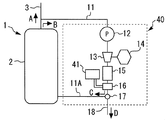
次に、スケール洗浄処理を実行する他の構成として、超音波振とうを用いる場合について説明する。図8は、本発明の実施の形態1において、水処理装置に超音波振とう装置を搭載した第3の変形例を示す要部拡大図である。この図に示す水処理装置40は、洗浄手段としての超音波振とう装置41を備えている。超音波振とう装置41は、制御装置により制御されるもので、スケール分離部16を微細振動(超音波振とう)させる機能を備えている。なお、超音波振とう装置41により発生させる振動の強さは、スケール分離部16の構成材料、構造、強度等により決定される。
(Ultrasonic shaking device)
Next, the case where ultrasonic shaking is used as another configuration for executing the scale cleaning process will be described. FIG. 8 is a main part enlarged view showing a third modified example in which an ultrasonic shaking device is mounted on the water treatment device in the first embodiment of the present invention. The water treatment device 40 shown in this figure includes an ultrasonic shaking device 41 as a cleaning means. The ultrasonic shaking device 41 is controlled by a control device and has a function of causing the scale separation unit 16 to vibrate (ultrasonic shaking). Note that the strength of vibration generated by the ultrasonic shaking device 41 is determined by the constituent material, structure, strength, and the like of the scale separation unit 16.
スケール洗浄処理では、制御装置により超音波振とう装置41を作動させ、スケール分離部16に微細振動を発生させる。この結果、スケール分離部16に蓄積されたスケールは、微細振動を受けてスケール分離部16の壁面から浮き上がり、水中に浮遊した状態となる。浮遊したスケールは、流路切換弁17及び排水配管18を介して追焚戻し配管6に排出されるので、スケール分離部16を洗浄することができる。
In the scale cleaning process, the control device activates the ultrasonic shaking device 41 to generate fine vibrations in the scale separation unit 16. As a result, the scale accumulated in the scale separation unit 16 is lifted from the wall surface of the scale separation unit 16 by being subjected to fine vibration, and is suspended in water. Since the floated scale is discharged to the return return pipe 6 through the flow path switching valve 17 and the drain pipe 18, the scale separator 16 can be washed.
なお、実施の形態1では、貯湯タンク2内の水を水処理装置10に導入する手段として、取水ポンプ12を例示した。しかし、本発明はこれに限らず、ポンプ以外の機器により貯湯タンク2から水処理装置10に水を導入してもよく、または、ポンプ等の機器を用いずに、貯湯タンク2内の水が自然落下により水処理装置10に流入する構成としてもよい。また、実施の形態1では、取水ポンプ12をスケール分離部16の上流側に配置する場合を例示したが、本発明はこれに限らず、取水ポンプ12をスケール分離部16の下流側に配置する構成としてもよい。この構成によれば、取水ポンプ12に対するスケールの付着を抑制することができる。
In the first embodiment, the water intake pump 12 is exemplified as means for introducing the water in the hot water storage tank 2 into the water treatment device 10. However, the present invention is not limited to this, and water may be introduced from the hot water storage tank 2 to the water treatment apparatus 10 by equipment other than the pump, or the water in the hot water storage tank 2 may be removed without using equipment such as a pump. It is good also as a structure which flows in into the water treatment apparatus 10 by natural fall. Moreover, in Embodiment 1, although the case where the intake pump 12 was arrange | positioned in the upstream of the scale separation part 16 was illustrated, this invention is not limited to this, The intake pump 12 is arrange | positioned in the downstream of the scale separation part 16 It is good also as a structure. According to this configuration, adhesion of scale to the water intake pump 12 can be suppressed.
また、実施の形態1では、排水配管18を追焚戻し配管6に接続し、スケール洗浄処理で発生した洗浄後の廃水を追焚戻し配管6に排出する場合を例示した。この構成によれば、洗浄後の廃水を追焚戻し配管6から浴槽9に流入させることができ、ユーザ等は、浴槽9に溜まった廃水を抜くだけで、廃水の処理を容易に行うことができる。従って、給湯装置1に搭載された既存の配管を利用して、スケール洗浄処理を効率よく行うことができ、給湯装置1のメンテナンス性を向上させることができる。
Further, in the first embodiment, the drain pipe 18 is connected to the return pipe 6 and the waste water after the cleaning generated in the scale cleaning process is discharged to the return pipe 6. According to this structure, the waste water after washing can be caused to flow into the bathtub 9 from the return pipe 6, and the user or the like can easily treat the waste water simply by removing the waste water accumulated in the bathtub 9. it can. Therefore, the scale cleaning process can be efficiently performed using the existing piping mounted on the hot water supply apparatus 1, and the maintainability of the hot water supply apparatus 1 can be improved.
一方、本発明において、排水配管18の接続先は、追焚戻し配管6に限定されるものではない。即ち、排水配管18は、追焚戻し配管6以外の配管に接続してもよいし、専用の廃水容器、廃水設備等に接続可能な構成としてもよい。具体例を挙げると、排水配管18は、例えば追焚往き配管5に接続してもよく、これによっても追焚戻し配管6に接続した場合と同様の効果を得ることができる。
On the other hand, in the present invention, the connection destination of the drain pipe 18 is not limited to the tracking return pipe 6. In other words, the drain pipe 18 may be connected to a pipe other than the return pipe 6 or may be configured to be connected to a dedicated waste water container, a waste water facility, or the like. As a specific example, the drain pipe 18 may be connected to, for example, the follow-up piping 5, and the same effect as when connected to the follow-up return pipe 6 can be obtained.
また、実施の形態1では、スケール除去処理及びスケール洗浄処理以外の運転を行う場合に、流路切換弁17により取水回路11を排水配管18から遮断し、排水配管18を行き止まりの状態に保持するのが好ましい。これにより、例えば追焚運転が実行されて追焚往き配管5及び追焚戻し配管6に浴槽水が循環したとしても、この浴槽水がスケール分離部16等に逆流するのを防止することができる。
Further, in the first embodiment, when an operation other than the scale removal process and the scale cleaning process is performed, the intake circuit 11 is shut off from the drain pipe 18 by the flow path switching valve 17, and the drain pipe 18 is held in a dead end state. Is preferred. Thereby, for example, even if the chasing operation is executed and the bath water is circulated through the chasing return pipe 5 and the chasing return pipe 6, it is possible to prevent the bath water from flowing back to the scale separation unit 16 and the like. .
以上詳述した通り、本実施の形態によれば、給湯装置1が取扱う水に含まれるスケール成分を水処理装置10により効率よく除去することができる。これにより、給湯装置1の機能を維持するために必要な部分、即ち、スケールから保護したい部分である貯湯タンク2、熱交換器4、追焚往き配管5、追焚戻し配管6等にスケールが付着して蓄積されるのを安定的に抑制することができる。しかも、本実施の形態では、水質を酸性化してスケール成分を水溶した状態に保持するわけではないので、水質または水温が変動した場合でも、スケールが想定外の部位で析出するのを回避することができる。従って、特に給湯装置1においては、熱交換器4等にスケールが付着することで熱交換器4の性能及び給湯効率が低下するのを抑制し、給湯装置1の機能を安定的に発揮させることができる。
As described in detail above, according to the present embodiment, the water treatment device 10 can efficiently remove scale components contained in the water handled by the hot water supply device 1. As a result, the scale is placed on the parts necessary for maintaining the function of the hot water supply device 1, that is, the hot water storage tank 2, the heat exchanger 4, the additional delivery pipe 5, the additional return pipe 6 and the like that are to be protected from the scale. It is possible to stably suppress adhesion and accumulation. Moreover, in this embodiment, since the water quality is not acidified and the scale components are not kept in a water-soluble state, even when the water quality or the water temperature fluctuates, it is avoided that the scale is deposited at an unexpected part. Can do. Therefore, particularly in the hot water supply apparatus 1, it is possible to suppress the performance and the hot water supply efficiency of the heat exchanger 4 from being deteriorated due to the scale adhering to the heat exchanger 4 or the like, and to stably exhibit the functions of the hot water supply apparatus 1. Can do.
なお、前記実施の形態1では、スケール反応部15として反応槽15A及び反応流路15Bの構成を例示し、スケール分離部16としてフィルタ16A、加熱型分離器16B及び電極反応型分離器16Cの構成を例示し、第1から第3の変形例等として、気泡破壊装置21、洗浄液供給装置31及び超音波振とう装置41の構成を例示した。本発明は、これらの構成のうち組合わせが可能な一部の構成を組合わせたシステム、及び、例示した全ての構成を組合わせたシステムも含むものである。
In the first embodiment, the configuration of the reaction tank 15A and the reaction channel 15B is illustrated as the scale reaction unit 15, and the configuration of the filter 16A, the heating type separator 16B, and the electrode reaction type separator 16C as the scale separation unit 16. As the first to third modifications, the configurations of the bubble destruction device 21, the cleaning liquid supply device 31, and the ultrasonic shaking device 41 are illustrated. The present invention also includes a system that combines some of the configurations that can be combined, and a system that combines all the illustrated configurations.
また、実施の形態1では、水処理装置10,20,30,40を給湯装置1に適用する場合を例示した。しかし、本発明は給湯装置に限らず、スケール成分を含む水が循環する各種の装置、配管、水槽等を備えた設備に適用することができる。具体例を挙げると、本発明は、温水を利用する床暖房システムを含む暖房装置、洗濯機等の設備に適用することができる。
Moreover, in Embodiment 1, the case where the water treatment apparatus 10, 20, 30, 40 was applied to the hot water supply apparatus 1 was illustrated. However, the present invention is not limited to a hot water supply device, and can be applied to facilities equipped with various devices, piping, water tanks, and the like through which water containing scale components circulates. As a specific example, the present invention can be applied to facilities such as a heating apparatus and a washing machine including a floor heating system using hot water.