WO2015049835A1 - リチウムイオン二次電池 - Google Patents
リチウムイオン二次電池 Download PDFInfo
- Publication number
- WO2015049835A1 WO2015049835A1 PCT/JP2014/004644 JP2014004644W WO2015049835A1 WO 2015049835 A1 WO2015049835 A1 WO 2015049835A1 JP 2014004644 W JP2014004644 W JP 2014004644W WO 2015049835 A1 WO2015049835 A1 WO 2015049835A1
- Authority
- WO
- WIPO (PCT)
- Prior art keywords
- layer
- active material
- electrode
- secondary battery
- lithium ion
- Prior art date
- Legal status (The legal status is an assumption and is not a legal conclusion. Google has not performed a legal analysis and makes no representation as to the accuracy of the status listed.)
- Ceased
Links
Images




Classifications
-
- H—ELECTRICITY
- H01—ELECTRIC ELEMENTS
- H01M—PROCESSES OR MEANS, e.g. BATTERIES, FOR THE DIRECT CONVERSION OF CHEMICAL ENERGY INTO ELECTRICAL ENERGY
- H01M4/00—Electrodes
- H01M4/02—Electrodes composed of, or comprising, active material
- H01M4/36—Selection of substances as active materials, active masses, active liquids
- H01M4/362—Composites
- H01M4/366—Composites as layered products
-
- H—ELECTRICITY
- H01—ELECTRIC ELEMENTS
- H01M—PROCESSES OR MEANS, e.g. BATTERIES, FOR THE DIRECT CONVERSION OF CHEMICAL ENERGY INTO ELECTRICAL ENERGY
- H01M10/00—Secondary cells; Manufacture thereof
- H01M10/05—Accumulators with non-aqueous electrolyte
- H01M10/052—Li-accumulators
- H01M10/0525—Rocking-chair batteries, i.e. batteries with lithium insertion or intercalation in both electrodes; Lithium-ion batteries
-
- H—ELECTRICITY
- H01—ELECTRIC ELEMENTS
- H01M—PROCESSES OR MEANS, e.g. BATTERIES, FOR THE DIRECT CONVERSION OF CHEMICAL ENERGY INTO ELECTRICAL ENERGY
- H01M4/00—Electrodes
- H01M4/02—Electrodes composed of, or comprising, active material
- H01M4/04—Processes of manufacture in general
- H01M4/0402—Methods of deposition of the material
- H01M4/0404—Methods of deposition of the material by coating on electrode collectors
-
- H—ELECTRICITY
- H01—ELECTRIC ELEMENTS
- H01M—PROCESSES OR MEANS, e.g. BATTERIES, FOR THE DIRECT CONVERSION OF CHEMICAL ENERGY INTO ELECTRICAL ENERGY
- H01M4/00—Electrodes
- H01M4/02—Electrodes composed of, or comprising, active material
- H01M4/13—Electrodes for accumulators with non-aqueous electrolyte, e.g. for lithium-accumulators; Processes of manufacture thereof
-
- H—ELECTRICITY
- H01—ELECTRIC ELEMENTS
- H01M—PROCESSES OR MEANS, e.g. BATTERIES, FOR THE DIRECT CONVERSION OF CHEMICAL ENERGY INTO ELECTRICAL ENERGY
- H01M4/00—Electrodes
- H01M4/02—Electrodes composed of, or comprising, active material
- H01M4/13—Electrodes for accumulators with non-aqueous electrolyte, e.g. for lithium-accumulators; Processes of manufacture thereof
- H01M4/139—Processes of manufacture
-
- H—ELECTRICITY
- H01—ELECTRIC ELEMENTS
- H01M—PROCESSES OR MEANS, e.g. BATTERIES, FOR THE DIRECT CONVERSION OF CHEMICAL ENERGY INTO ELECTRICAL ENERGY
- H01M2220/00—Batteries for particular applications
- H01M2220/20—Batteries in motive systems, e.g. vehicle, ship, plane
-
- H—ELECTRICITY
- H01—ELECTRIC ELEMENTS
- H01M—PROCESSES OR MEANS, e.g. BATTERIES, FOR THE DIRECT CONVERSION OF CHEMICAL ENERGY INTO ELECTRICAL ENERGY
- H01M4/00—Electrodes
- H01M4/02—Electrodes composed of, or comprising, active material
- H01M4/13—Electrodes for accumulators with non-aqueous electrolyte, e.g. for lithium-accumulators; Processes of manufacture thereof
- H01M4/131—Electrodes based on mixed oxides or hydroxides, or on mixtures of oxides or hydroxides, e.g. LiCoOx
-
- H—ELECTRICITY
- H01—ELECTRIC ELEMENTS
- H01M—PROCESSES OR MEANS, e.g. BATTERIES, FOR THE DIRECT CONVERSION OF CHEMICAL ENERGY INTO ELECTRICAL ENERGY
- H01M4/00—Electrodes
- H01M4/02—Electrodes composed of, or comprising, active material
- H01M4/13—Electrodes for accumulators with non-aqueous electrolyte, e.g. for lithium-accumulators; Processes of manufacture thereof
- H01M4/139—Processes of manufacture
- H01M4/1391—Processes of manufacture of electrodes based on mixed oxides or hydroxides, or on mixtures of oxides or hydroxides, e.g. LiCoOx
-
- H—ELECTRICITY
- H01—ELECTRIC ELEMENTS
- H01M—PROCESSES OR MEANS, e.g. BATTERIES, FOR THE DIRECT CONVERSION OF CHEMICAL ENERGY INTO ELECTRICAL ENERGY
- H01M4/00—Electrodes
- H01M4/02—Electrodes composed of, or comprising, active material
- H01M4/36—Selection of substances as active materials, active masses, active liquids
- H01M4/48—Selection of substances as active materials, active masses, active liquids of inorganic oxides or hydroxides
- H01M4/50—Selection of substances as active materials, active masses, active liquids of inorganic oxides or hydroxides of manganese
- H01M4/505—Selection of substances as active materials, active masses, active liquids of inorganic oxides or hydroxides of manganese of mixed oxides or hydroxides containing manganese for inserting or intercalating light metals, e.g. LiMn2O4 or LiMn2OxFy
-
- H—ELECTRICITY
- H01—ELECTRIC ELEMENTS
- H01M—PROCESSES OR MEANS, e.g. BATTERIES, FOR THE DIRECT CONVERSION OF CHEMICAL ENERGY INTO ELECTRICAL ENERGY
- H01M4/00—Electrodes
- H01M4/02—Electrodes composed of, or comprising, active material
- H01M4/36—Selection of substances as active materials, active masses, active liquids
- H01M4/48—Selection of substances as active materials, active masses, active liquids of inorganic oxides or hydroxides
- H01M4/52—Selection of substances as active materials, active masses, active liquids of inorganic oxides or hydroxides of nickel, cobalt or iron
- H01M4/525—Selection of substances as active materials, active masses, active liquids of inorganic oxides or hydroxides of nickel, cobalt or iron of mixed oxides or hydroxides containing iron, cobalt or nickel for inserting or intercalating light metals, e.g. LiNiO2, LiCoO2 or LiCoOxFy
-
- Y—GENERAL TAGGING OF NEW TECHNOLOGICAL DEVELOPMENTS; GENERAL TAGGING OF CROSS-SECTIONAL TECHNOLOGIES SPANNING OVER SEVERAL SECTIONS OF THE IPC; TECHNICAL SUBJECTS COVERED BY FORMER USPC CROSS-REFERENCE ART COLLECTIONS [XRACs] AND DIGESTS
- Y02—TECHNOLOGIES OR APPLICATIONS FOR MITIGATION OR ADAPTATION AGAINST CLIMATE CHANGE
- Y02E—REDUCTION OF GREENHOUSE GAS [GHG] EMISSIONS, RELATED TO ENERGY GENERATION, TRANSMISSION OR DISTRIBUTION
- Y02E60/00—Enabling technologies; Technologies with a potential or indirect contribution to GHG emissions mitigation
- Y02E60/10—Energy storage using batteries
-
- Y—GENERAL TAGGING OF NEW TECHNOLOGICAL DEVELOPMENTS; GENERAL TAGGING OF CROSS-SECTIONAL TECHNOLOGIES SPANNING OVER SEVERAL SECTIONS OF THE IPC; TECHNICAL SUBJECTS COVERED BY FORMER USPC CROSS-REFERENCE ART COLLECTIONS [XRACs] AND DIGESTS
- Y02—TECHNOLOGIES OR APPLICATIONS FOR MITIGATION OR ADAPTATION AGAINST CLIMATE CHANGE
- Y02P—CLIMATE CHANGE MITIGATION TECHNOLOGIES IN THE PRODUCTION OR PROCESSING OF GOODS
- Y02P70/00—Climate change mitigation technologies in the production process for final industrial or consumer products
- Y02P70/50—Manufacturing or production processes characterised by the final manufactured product
-
- Y—GENERAL TAGGING OF NEW TECHNOLOGICAL DEVELOPMENTS; GENERAL TAGGING OF CROSS-SECTIONAL TECHNOLOGIES SPANNING OVER SEVERAL SECTIONS OF THE IPC; TECHNICAL SUBJECTS COVERED BY FORMER USPC CROSS-REFERENCE ART COLLECTIONS [XRACs] AND DIGESTS
- Y02—TECHNOLOGIES OR APPLICATIONS FOR MITIGATION OR ADAPTATION AGAINST CLIMATE CHANGE
- Y02T—CLIMATE CHANGE MITIGATION TECHNOLOGIES RELATED TO TRANSPORTATION
- Y02T10/00—Road transport of goods or passengers
- Y02T10/60—Other road transportation technologies with climate change mitigation effect
- Y02T10/70—Energy storage systems for electromobility, e.g. batteries
Definitions
- the present invention relates to a lithium ion secondary battery, and more particularly to a lithium ion secondary battery with improved discharge characteristics.
- Patent Document 1 describes an electrode in which the solid content concentration decreases from the current collector side to the upper layer (electrolyte side) in the active material layer of the thick film electrode.
- Patent Document 2 describes an electrode in which, in an active material layer of a secondary battery, an active material having a smaller particle diameter is disposed on an upper layer (electrolyte side) and portions having different pore sizes are provided.
- Patent Document 1 in the lithium ion secondary battery, the reactivity of the upper layer (electrolyte side) of the active material layer of the thick film electrode increases in a short period of time, but the reaction mitigates toward the current collector side. Therefore, when constant power discharge is performed for a predetermined time, there is a problem that the reaction of the lower layer portion (current collector side) is reduced and the speed of the battery voltage drop is increased.
- the present invention has been made in view of the above problems, and provides a lithium ion secondary battery that promotes the reactivity of the current collector side of the electrode and improves the constant output discharge performance.
- a lithium ion secondary battery includes a first active material, a lower layer formed of a conductive second active material different from the first active material, the first active material, An upper layer formed from the second active material, and the lower layer includes a first lower layer forming slurry containing the first active material on a current collector and the second active material.
- the second lower layer forming slurry contained is formed by alternately applying stripes, and the upper layer includes the first active material containing the first active material on the second lower layer forming slurry.
- the present invention it is possible to provide a lithium ion secondary battery that promotes the reactivity of the electrode on the collector side and improves the constant output discharge performance.
- FIG. 9 is a schematic diagram showing the lithium ion secondary battery 100 according to the first embodiment of the present invention.
- the lithium ion secondary battery 100 includes an electrode 1 (positive electrode), an electrode 40 (negative electrode), and an electrolyte 50.
- FIG. 1 is a schematic diagram showing an electrode 1 of a lithium ion secondary battery according to Embodiment 1 of the present invention.
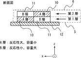
- the electrode 1 includes a current collector 12 made of a metal foil, a first layer 5 (lower layer) having one surface formed on the current collector, and a second layer 6 (upper layer) formed on the other surface side of the first layer. ).
- FIG. 2 is a cross-sectional view of a portion of the electrode 1 surrounded by a circle in FIG.
- the first layer 5 includes an A layer 10 (a layer containing a first active material), and a conductive B layer 11 (containing a second active material) different from the A layer 10. Layer).
- the first layer 5 has a stripe shape in which a plurality of strip-shaped A layers 10 having a certain width and a plurality of strip-shaped B layers 11 having a certain width are alternately arranged.
- the second layer 6 has the same structure as the first layer 5 formed from the A layer 10 and the B layer 11.
- the A layer 10 of the second layer 6 is formed on the other surface side of the B layer 11 of the first layer 5, and the B layer 11 of the second layer 6 is formed on the other surface side of the A layer 10 a of the first layer 5. Is formed. That is, in the electrode 1, the A layer 10 and the B layer 11 are alternately arranged in the z-axis direction and the y-axis direction from the current collector 12 side.
- the A layer 10 is an active material having a high reactivity and a small capacity.
- the A layer 10 is formed, for example, containing an active material having a small particle size (2 to 5 ⁇ m).
- the B layer 10 is an active material having a low reactivity and a large capacity.
- the B layer 11 is formed, for example, containing an active material having a large particle size (7 to 12 ⁇ m).
- LiNi 1/3 Mn 1/3 Co 1/3 O 2 can be used as the active material.
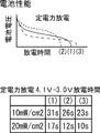
- FIG. 3 is a graph showing reaction characteristics of the lithium ion secondary battery in the cases (1) to (3) of various electrodes described later.
- the graph of FIG. 3 shows changes with time in voltage when the lithium ion secondary battery is discharged at a constant power in the cases (1) to (3) of various electrodes.
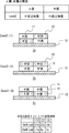
- FIG. 4 is a cross-sectional view of the electrodes 1a, 1b and 1c when various electrodes are formed in the patterns (1) to (3).
- the table in FIG. 4 shows the reaction time in the cases (1) to (3) until the lithium ion secondary battery 100 of various electrodes is discharged at a constant power and the voltage drops from 4.1 to 3.0%. Is shown.
- the unit of the set power value is a value obtained by setting the output power value and dividing the set value by the effective area of various electrodes (mW / cm 2 ).
- Case 1- (2) in FIG. 4 a case where the second layer is formed only by the A layer 10 and the electrode 1b is formed by only the B layer as the first layer will be described.
- the average reaction voltage increases.
- the reaction during discharge takes place near the surface layer (electrolyte 50 side) of the A layer 10 and so-called salt withering occurs.
- the electrode 1b formed in the pattern (2) the reactivity of the entire electrode is lowered and the discharge time is shortened.
- the discharge characteristics when the electrode 1 (electrode 1a) according to the first embodiment of the present invention is used will be described (1).
- the A layer 10 and the B layer 11 are alternately arranged in two layers as in Case 1- (1) of FIG. 4, as shown in the tables of FIGS. 3 and 4, intermediate between the cases of (2) and (3) Reaction exhibiting excellent characteristics can be obtained. That is, the electrode 1a exhibits characteristics that the average voltage is higher than that in the case of (3) and the discharge time to the lower limit voltage (3.0%) is longer than that in the case of (2).
- the electrode 1 according to this embodiment when used, the reactivity on the electrolyte 50 side and the current collector side is promoted, and the lithium ion secondary battery 100 with improved constant output discharge performance is realized.
- FIG. 7 shows the mixing ratio of the slurry (paste) of the active material when the first layer 5 and the second layer 6 are formed on the current collector 12 of the electrode 1 according to the present embodiment using gravure pattern printing. is there.
- LiNi 1/3 Mn 1/3 Co 1/3 O 2 is used as the active material.
- Acetylene black (HS-100) is used as a conductive aid.
- Polyvinylidene fluoride (PVdF) is used as the binder.
- N-methyl-2-pyrrolidone (NMP) is used as the solvent.
- a slurry making apparatus is used for making the slurry.
- a general planetary mixer can be used as the apparatus.
- an active material and a conductive additive are mixed.
- a binder is added to the mixture and kneaded.
- NMP is put into the kneaded product and mixed and kneaded.
- FIG. 8 is a schematic diagram showing a method of applying a slurry containing an active material to the current collector 12 using gravure pattern printing.
- the slurry 23 is rotated clockwise around the x axis while being uniformly applied in the x direction to the lower part of the gravure roll 21 ( ⁇ z direction). Then, the gravure roll 21 is rotated and the slurry 23 is scraped off at regular intervals by a doctor blade 22 having grooves at regular intervals. The slurry 23 scraped off at regular intervals is transferred to the blanket roll 20. The slurry 23 transferred to the blanket roll 20 is transferred and applied to the aluminum foil 24 in a stripe shape.
- the application condition is, for example, 0.8 m / min.
- the drying condition after applying the slurry 23 is, for example, 180 degrees.
- the A layer 10 containing the first active material and the B layer 11 containing the second active material are formed 2
- the first layer 5 (lower layer) is formed by applying the A layer 10 and the B layer 11 alternately in a stripe pattern. That is, in the first layer 5 (lower layer), the first lower layer forming slurry containing the first active material and the second lower layer forming slurry containing the second active material are alternately arranged on the current collector. It is formed by applying in stripes.
- the second layer 6 (upper layer) A is formed twice for forming the A layer 10 and the B layer 11.
- the layer forming slurry is applied in the form of stripes on the B layer 11 forming slurry of the first layer 5 (lower layer), and the B layer 11 forming slurry of the second layer 6 (upper layer) is further applied to the first layer 5 (lower layer).
- the second layer 6 (upper layer) is formed by applying a multilayer coating on the slurry for forming the A layer 10).
- the second layer 6 (upper layer) is formed by applying the first upper layer forming slurry containing the first active material on the second lower layer forming slurry, and the first lower layer forming slurry.
- the second slurry for forming the upper layer containing the second active material is applied in multiple layers.
- the electrode 1 according to the present embodiment is obtained by performing the slurry application step four times in total.
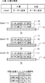
- FIG. 5 is a cross-sectional view of the electrodes 2a, 2b and 2c when various electrodes are formed in the patterns (1) to (3).
- the experimental method and the patterns (1) to (3) of each electrode are the same as those in the first embodiment, and redundant description is omitted.
- Table 5 shows the discharge time to the lower limit voltage (3.0 kg) when performing constant power discharge. As shown in the table of FIG. 5, the electrode 2a having the pattern (1) has the characteristic that the discharge time is the longest.
- the electrode 2 according to this embodiment when used, the reactivity on the electrolyte 50 side and current collector side is promoted, and a lithium ion secondary battery with improved constant output discharge performance is realized.
- the characteristics of the electrode 3 implemented when the active materials of the A layer 10 and the B layer 11 are changed from those in the first embodiment will be described.
- the A layer 10 uses an active material with a high carbon content
- the B layer 11 uses an active material with a low carbon content.
- FIG. 6 is a cross-sectional view of the electrodes 3a, 3b, and 3c when various electrodes are formed in the patterns (1) to (3).
- the experimental method and the patterns (1) to (3) of each electrode are the same as those in the first embodiment, and redundant description is omitted.
- the discharge time up to the lower limit voltage (3.0 kg) when performing constant power discharge is shown in the table of FIG.
- the electrode 3a having the pattern (1) has the characteristic that the discharge time is the longest.
- the electrode 3 according to this embodiment when used, the reactivity on the electrolyte 50 side and the current collector side is promoted, and a lithium ion secondary battery with improved constant output discharge performance is realized.
Landscapes
- Chemical & Material Sciences (AREA)
- Engineering & Computer Science (AREA)
- Chemical Kinetics & Catalysis (AREA)
- Electrochemistry (AREA)
- General Chemical & Material Sciences (AREA)
- Manufacturing & Machinery (AREA)
- Materials Engineering (AREA)
- Composite Materials (AREA)
- Battery Electrode And Active Subsutance (AREA)
- Secondary Cells (AREA)
Abstract
Description
以下、本発明の実施の形態1を図面を用いて説明する。図9は、本発明の実施の形態1にかかるリチウムイオン二次電池100を示した概要図である。リチウムイオン二次電池100は電極1(陽電極)と、電極40(陰電極)と、電解質50とを備える。
電極1は、金属箔からなる集電体12と、一面側が集電体上に形成された第1層5(下層)と、第1層の他面側に形成された第2層6(上層)とを備える。図2は、電極1の断面であり図1の○で囲んだ部分の断面図である。図1及び図2に示すように、第1層5はA層10(第1の活物質を含有する層)と、A層10と異なる導電性のB層11(第2の活物質を含有する層)から形成されている。
第2層6は、A層10とB層11から形成された第1層5と同様の構造を有する。そして、第2層6のA層10は、第1層5のB層11の他面側に形成され、第2層6のB層11は、第1層5のA層10aの他面側に形成されている。即ち、電極1は、集電体12側からz軸方向及びy軸方向に対してA層10とB層11とが交互に配置されている。
B層10は、反応性が小さく、かつ容量が大きい活物質である。B層11は例えば大粒径(7~12μm)の活物質を含有して形成される。活物質は例えばLiNi1/3Mn1/3Co1/3O2を用いることができる。
まず、活物質と導電助剤とを混合する。そして、混合物に結着剤を入れ、混練する。さらに、混練物にNMPを入れ、混合及び混練する。上記の工程により、活物質を含有するスラリーを得る。
上記のように、スラリー塗布工程を合計4回行うことにより、本実施の形態にかかる電極1を得る。
次に、A層10、B層11の活物質を実施の形態1の場合と変更した場合で実施した電極2の特性について説明する。本実施の形態ではA層10は中空活物質、B層11は中実活物質を用いる。図5は、各種の電極を(1)~(3)のパターンで形成した場合の電極2a、2b、2cの断面図である。実験方法、各電極のパターン(1)~(3)は実施の形態1と同様であり、重複する説明は省略する。
次に、A層10、B層11の活物質を実施の形態1の場合と変更した場合で実施した電極3の特性について説明する。本実施の形態ではA層10はカーボン含有量が多く、B層11はカーボン含有量が少ない活物質を用いる。
1a 電極
1b 電極
1c 電極
2a 電極
2b 電極
2c 電極
3a 電極
3b 電極
3c 電極
5 第1層(下層)
6 第2層(上層)
10 A層
11 B層
12 集電体
20 ブランケットロール
21 グラビアロール版
22 ドクターブレード
23 スラリー
24 金属箔
40 電極(陰電極)
50 電解質
100 リチウムイオン二次電池
Claims (1)
- 第1の活物質と前記第1の活物質と異なる導電性を有する第2の活物質とから形成された下層と、
前記第1の活物質と前記第2の活物質とから形成された上層と、を有し、
前記下層は、集電体上に前記第1の活物質を含有する第1の下層形成用スラリーと前記第2の活物質を含有する第2の下層形成用スラリーとが交互にストライプ状に塗布されることにより形成され、
前記上層は、前記第2の下層形成用スラリー上に前記第1の活物質を含有する第1の上層形成用スラリーが重層塗布され、かつ、前記第1の下層形成用スラリー上に前記第2の活物質を含有する第2の上層形成用スラリーが重層塗布されることにより形成された、
電極を備える、リチウムイオン二次電池。
Priority Applications (2)
| Application Number | Priority Date | Filing Date | Title |
|---|---|---|---|
| CN201480053125.9A CN105580166A (zh) | 2013-10-02 | 2014-09-10 | 锂离子二次电池 |
| US15/026,492 US20160226064A1 (en) | 2013-10-02 | 2014-09-10 | Lithium ion rechargeable battery |
Applications Claiming Priority (2)
| Application Number | Priority Date | Filing Date | Title |
|---|---|---|---|
| JP2013-206951 | 2013-10-02 | ||
| JP2013206951A JP2015072753A (ja) | 2013-10-02 | 2013-10-02 | リチウムイオン二次電池 |
Publications (1)
| Publication Number | Publication Date |
|---|---|
| WO2015049835A1 true WO2015049835A1 (ja) | 2015-04-09 |
Family
ID=52778441
Family Applications (1)
| Application Number | Title | Priority Date | Filing Date |
|---|---|---|---|
| PCT/JP2014/004644 Ceased WO2015049835A1 (ja) | 2013-10-02 | 2014-09-10 | リチウムイオン二次電池 |
Country Status (4)
| Country | Link |
|---|---|
| US (1) | US20160226064A1 (ja) |
| JP (1) | JP2015072753A (ja) |
| CN (1) | CN105580166A (ja) |
| WO (1) | WO2015049835A1 (ja) |
Families Citing this family (11)
| Publication number | Priority date | Publication date | Assignee | Title |
|---|---|---|---|---|
| US10115964B2 (en) * | 2014-12-08 | 2018-10-30 | Palo Alto Research Center Incorporated | Advanced Si-C composite anode electrode for high energy density and longer cycle life |
| US10818928B2 (en) | 2014-12-15 | 2020-10-27 | Samsung Sdi Co., Ltd. | Electrode for rechargeable lithium battery, rechargeable lithium battery, and method of fabricating electrode for rechargeable lithium battery |
| JP6588204B2 (ja) * | 2014-12-15 | 2019-10-09 | 三星エスディアイ株式会社Samsung SDI Co., Ltd. | リチウムイオン二次電池用電極、リチウムイオン二次電池及びリチウムイオン二次電池用電極の製造方法 |
| PL3343675T3 (pl) * | 2016-07-04 | 2021-05-17 | Lg Chem, Ltd. | Elektroda ujemna i akumulator zawierający tą elektrodę ujemną |
| CN108352506B (zh) * | 2016-07-04 | 2021-08-24 | 株式会社Lg化学 | 正极和包含该正极的二次电池 |
| JP6859864B2 (ja) * | 2017-03-08 | 2021-04-14 | 株式会社リコー | 正極、電極素子、非水電解液蓄電素子 |
| KR102800327B1 (ko) * | 2018-11-20 | 2025-04-28 | 삼성전자주식회사 | 전극 구조체 및 그 제조방법과, 전극 구조체를 포함하는 이차 전지 |
| US20240387810A1 (en) * | 2021-09-30 | 2024-11-21 | Panasonic Intellectual Property Management Co., Ltd. | Negative electrode for rechargeable battery, and rechargeable battery |
| JPWO2024004837A1 (ja) * | 2022-06-29 | 2024-01-04 | ||
| WO2024095670A1 (ja) * | 2022-10-31 | 2024-05-10 | パナソニックエナジー株式会社 | 二次電池用正極および二次電池 |
| CN119480906B (zh) * | 2024-10-18 | 2025-12-19 | 浙江锂威能源科技有限公司 | 负极极片、电池以及用电设备 |
Citations (7)
| Publication number | Priority date | Publication date | Assignee | Title |
|---|---|---|---|---|
| JP2005050755A (ja) * | 2003-07-31 | 2005-02-24 | Nissan Motor Co Ltd | 非水電解質電池 |
| JP2005135599A (ja) * | 2003-10-28 | 2005-05-26 | Nissan Motor Co Ltd | 超薄膜の高出力電池用電極およびこれを用いた高出力電池 |
| JP2007042385A (ja) * | 2005-08-02 | 2007-02-15 | Nissan Motor Co Ltd | 電池用電極 |
| JP2009004181A (ja) * | 2007-06-20 | 2009-01-08 | Nissan Motor Co Ltd | 電池用電極 |
| JP2010238426A (ja) * | 2009-03-30 | 2010-10-21 | Nissan Motor Co Ltd | リチウムイオン二次電池用負極およびこれを用いたリチウムイオン二次電池 |
| JP2012038539A (ja) * | 2010-08-06 | 2012-02-23 | Toyota Motor Corp | 電池 |
| JP2013058426A (ja) * | 2011-09-09 | 2013-03-28 | Dainippon Screen Mfg Co Ltd | リチウムイオン二次電池及びその製造方法 |
Family Cites Families (5)
| Publication number | Priority date | Publication date | Assignee | Title |
|---|---|---|---|---|
| JP2585707B2 (ja) * | 1988-04-21 | 1997-02-26 | 三井石油化学工業株式会社 | 積層不織布 |
| CN1019910C (zh) * | 1990-01-18 | 1993-02-17 | 北京东方化工厂 | 一种防止丙烯酸生产装置腐蚀的方法 |
| JP2011175739A (ja) * | 2010-02-23 | 2011-09-08 | Hitachi Ltd | リチウム二次電池及びその製造方法 |
| KR101199177B1 (ko) * | 2011-06-15 | 2012-11-07 | 삼성에스디아이 주식회사 | 이차 전지 |
| JP5753042B2 (ja) * | 2011-09-20 | 2015-07-22 | 株式会社Screenホールディングス | 電池用電極の製造方法および電池の製造方法 |
-
2013
- 2013-10-02 JP JP2013206951A patent/JP2015072753A/ja active Pending
-
2014
- 2014-09-10 WO PCT/JP2014/004644 patent/WO2015049835A1/ja not_active Ceased
- 2014-09-10 US US15/026,492 patent/US20160226064A1/en not_active Abandoned
- 2014-09-10 CN CN201480053125.9A patent/CN105580166A/zh active Pending
Patent Citations (7)
| Publication number | Priority date | Publication date | Assignee | Title |
|---|---|---|---|---|
| JP2005050755A (ja) * | 2003-07-31 | 2005-02-24 | Nissan Motor Co Ltd | 非水電解質電池 |
| JP2005135599A (ja) * | 2003-10-28 | 2005-05-26 | Nissan Motor Co Ltd | 超薄膜の高出力電池用電極およびこれを用いた高出力電池 |
| JP2007042385A (ja) * | 2005-08-02 | 2007-02-15 | Nissan Motor Co Ltd | 電池用電極 |
| JP2009004181A (ja) * | 2007-06-20 | 2009-01-08 | Nissan Motor Co Ltd | 電池用電極 |
| JP2010238426A (ja) * | 2009-03-30 | 2010-10-21 | Nissan Motor Co Ltd | リチウムイオン二次電池用負極およびこれを用いたリチウムイオン二次電池 |
| JP2012038539A (ja) * | 2010-08-06 | 2012-02-23 | Toyota Motor Corp | 電池 |
| JP2013058426A (ja) * | 2011-09-09 | 2013-03-28 | Dainippon Screen Mfg Co Ltd | リチウムイオン二次電池及びその製造方法 |
Also Published As
| Publication number | Publication date |
|---|---|
| CN105580166A (zh) | 2016-05-11 |
| JP2015072753A (ja) | 2015-04-16 |
| US20160226064A1 (en) | 2016-08-04 |
Similar Documents
| Publication | Publication Date | Title |
|---|---|---|
| WO2015049835A1 (ja) | リチウムイオン二次電池 | |
| US7759004B2 (en) | Electrode for lithium ion secondary batteries, lithium ion secondary battery using the same, and method for manufacturing the battery | |
| CN101546827B (zh) | 电极制造方法 | |
| JP7297060B2 (ja) | 互いに異なるバインダー含量を有する電極合剤領域を含む二次電池用極板及びそれを用いた二次電池用電極の製造方法 | |
| US20110206985A1 (en) | Lithium secondary battery and method for manufacturing the same | |
| KR102332441B1 (ko) | 비수전해질 이차전지용 음극 및 비수전해질 이차전지 | |
| CN103201882A (zh) | 包含多层电极活性材料层的电极和包含所述电极的二次电池 | |
| JP5288223B2 (ja) | 電池用電極の製造方法 | |
| JP2015146272A (ja) | 非水電解液二次電池用の負極の製造方法 | |
| JP2010062136A (ja) | 非水電解質二次電池 | |
| JP2015037008A (ja) | 非水電解質二次電池用の電極活物質層とその製造方法 | |
| CN104067423A (zh) | 电极的制造方法以及非水电解质电池的制造方法 | |
| JP5284933B2 (ja) | リチウム二次電池及びその製造方法 | |
| CN108155418A (zh) | 二次电池及二次电池的制造方法 | |
| JP5891884B2 (ja) | 非水電解液二次電池用電極の製造方法 | |
| KR20160027364A (ko) | 이차전지용 전극조립체 | |
| CN116868372A (zh) | 锂离子二次电池用负极、锂离子二次电池、CNT-Si糊剂的制造方法、锂离子二次电池用负极的制造方法、锂离子二次电池的制造方法 | |
| JP6588204B2 (ja) | リチウムイオン二次電池用電極、リチウムイオン二次電池及びリチウムイオン二次電池用電極の製造方法 | |
| JP2026500422A (ja) | 乾式電極の製造方法及び乾式電極の製造システム | |
| US20160190533A1 (en) | Electrode body | |
| JP4649862B2 (ja) | リチウムイオン二次電池及びその製造方法 | |
| JP2014175155A (ja) | 非水電解液二次電池用電極、その製造方法、及び非水電解液二次電池 | |
| JP2007095590A (ja) | 電子部品用電極−多孔質シート複合体およびその製造方法 | |
| JP2013073685A (ja) | 非水電解液二次電池用電極、その製造方法、及び非水電解液二次電池 | |
| KR101170172B1 (ko) | 리튬 2차전지용 정극합재도료의 제작방법 및 리튬2차전지용 정극 |
Legal Events
| Date | Code | Title | Description |
|---|---|---|---|
| WWE | Wipo information: entry into national phase |
Ref document number: 201480053125.9 Country of ref document: CN |
|
| 121 | Ep: the epo has been informed by wipo that ep was designated in this application |
Ref document number: 14850258 Country of ref document: EP Kind code of ref document: A1 |
|
| WWE | Wipo information: entry into national phase |
Ref document number: 15026492 Country of ref document: US |
|
| NENP | Non-entry into the national phase |
Ref country code: DE |
|
| 122 | Ep: pct application non-entry in european phase |
Ref document number: 14850258 Country of ref document: EP Kind code of ref document: A1 |