WO2015041180A1 - 印刷装置、印刷制御方法及びプログラム - Google Patents
印刷装置、印刷制御方法及びプログラム Download PDFInfo
- Publication number
- WO2015041180A1 WO2015041180A1 PCT/JP2014/074288 JP2014074288W WO2015041180A1 WO 2015041180 A1 WO2015041180 A1 WO 2015041180A1 JP 2014074288 W JP2014074288 W JP 2014074288W WO 2015041180 A1 WO2015041180 A1 WO 2015041180A1
- Authority
- WO
- WIPO (PCT)
- Prior art keywords
- recording medium
- fixing unit
- unit
- width
- type
- Prior art date
- Legal status (The legal status is an assumption and is not a legal conclusion. Google has not performed a legal analysis and makes no representation as to the accuracy of the status listed.)
- Ceased
Links
Images


Classifications
-
- G—PHYSICS
- G03—PHOTOGRAPHY; CINEMATOGRAPHY; ANALOGOUS TECHNIQUES USING WAVES OTHER THAN OPTICAL WAVES; ELECTROGRAPHY; HOLOGRAPHY
- G03G—ELECTROGRAPHY; ELECTROPHOTOGRAPHY; MAGNETOGRAPHY
- G03G15/00—Apparatus for electrographic processes using a charge pattern
- G03G15/20—Apparatus for electrographic processes using a charge pattern for fixing, e.g. by using heat
- G03G15/2003—Apparatus for electrographic processes using a charge pattern for fixing, e.g. by using heat using heat
- G03G15/2014—Apparatus for electrographic processes using a charge pattern for fixing, e.g. by using heat using heat using contact heat
- G03G15/2039—Apparatus for electrographic processes using a charge pattern for fixing, e.g. by using heat using heat using contact heat with means for controlling the fixing temperature
- G03G15/205—Apparatus for electrographic processes using a charge pattern for fixing, e.g. by using heat using heat using contact heat with means for controlling the fixing temperature specially for the mode of operation, e.g. standby, warming-up, error
-
- G—PHYSICS
- G03—PHOTOGRAPHY; CINEMATOGRAPHY; ANALOGOUS TECHNIQUES USING WAVES OTHER THAN OPTICAL WAVES; ELECTROGRAPHY; HOLOGRAPHY
- G03G—ELECTROGRAPHY; ELECTROPHOTOGRAPHY; MAGNETOGRAPHY
- G03G15/00—Apparatus for electrographic processes using a charge pattern
- G03G15/20—Apparatus for electrographic processes using a charge pattern for fixing, e.g. by using heat
- G03G15/2003—Apparatus for electrographic processes using a charge pattern for fixing, e.g. by using heat using heat
- G03G15/2014—Apparatus for electrographic processes using a charge pattern for fixing, e.g. by using heat using heat using contact heat
- G03G15/2017—Structural details of the fixing unit in general, e.g. cooling means, heat shielding means
-
- G—PHYSICS
- G03—PHOTOGRAPHY; CINEMATOGRAPHY; ANALOGOUS TECHNIQUES USING WAVES OTHER THAN OPTICAL WAVES; ELECTROGRAPHY; HOLOGRAPHY
- G03G—ELECTROGRAPHY; ELECTROPHOTOGRAPHY; MAGNETOGRAPHY
- G03G15/00—Apparatus for electrographic processes using a charge pattern
- G03G15/50—Machine control of apparatus for electrographic processes using a charge pattern, e.g. regulating differents parts of the machine, multimode copiers, microprocessor control
-
- G—PHYSICS
- G03—PHOTOGRAPHY; CINEMATOGRAPHY; ANALOGOUS TECHNIQUES USING WAVES OTHER THAN OPTICAL WAVES; ELECTROGRAPHY; HOLOGRAPHY
- G03G—ELECTROGRAPHY; ELECTROPHOTOGRAPHY; MAGNETOGRAPHY
- G03G15/00—Apparatus for electrographic processes using a charge pattern
- G03G15/65—Apparatus which relate to the handling of copy material
- G03G15/6517—Apparatus for continuous web copy material of plain paper, e.g. supply rolls; Roll holders therefor
-
- G—PHYSICS
- G03—PHOTOGRAPHY; CINEMATOGRAPHY; ANALOGOUS TECHNIQUES USING WAVES OTHER THAN OPTICAL WAVES; ELECTROGRAPHY; HOLOGRAPHY
- G03G—ELECTROGRAPHY; ELECTROPHOTOGRAPHY; MAGNETOGRAPHY
- G03G2215/00—Apparatus for electrophotographic processes
- G03G2215/00362—Apparatus for electrophotographic processes relating to the copy medium handling
- G03G2215/00443—Copy medium
- G03G2215/00447—Plural types handled
-
- G—PHYSICS
- G03—PHOTOGRAPHY; CINEMATOGRAPHY; ANALOGOUS TECHNIQUES USING WAVES OTHER THAN OPTICAL WAVES; ELECTROGRAPHY; HOLOGRAPHY
- G03G—ELECTROGRAPHY; ELECTROPHOTOGRAPHY; MAGNETOGRAPHY
- G03G2215/00—Apparatus for electrophotographic processes
- G03G2215/00362—Apparatus for electrophotographic processes relating to the copy medium handling
- G03G2215/00535—Stable handling of copy medium
- G03G2215/00717—Detection of physical properties
- G03G2215/00751—Detection of physical properties of sheet type, e.g. OHP
Definitions
- the present invention relates to a printing apparatus, a printing control method, and a program.
- a printing apparatus In a printing apparatus, generally, heat and pressure are applied by a roller to heat a transferred toner image and fix it on a recording medium.
- the heating width of the roller is wider than the recording width of the recording medium, the temperature of the portion of the roller where the recording medium does not pass rises.
- the printing operation may be stopped by the safety protection control, and the printing operation may not be resumed until the temperature falls below a predetermined temperature.
- Patent Document 1 when the temperature of the roller at the portion where the recording medium does not pass exceeds the predetermined temperature, the power supply to the heater is stopped, and the temperature difference between the roller where the recording medium passes and the portion where the recording medium does not pass. Discloses a technique for calculating the time until the temperature difference becomes a predetermined temperature difference and displaying the time.
- the present invention has been made in view of such a situation, and an object of the present invention is to provide a printing apparatus, a printing control method, and a program capable of preventing interruption of printing operation. Another object of the present invention is to provide a printing apparatus with high printing efficiency, a printing control method, and a program.
- a recording medium type reading unit that reads the type of the recording medium
- a fixing unit storage unit that selectively stores any one of a plurality of fixing units of different types
- a compatibility determination unit that determines whether the type of the fixing unit stored in the fixing unit storage unit matches the type of the recording medium read by the recording medium type reading unit; Equipped with
- one aspect of the printing control method is A recording medium type reading step of reading the recording medium type;
- one aspect of a program according to the present invention is On the computer A recording medium type reading process of reading the recording medium type; A fixing unit storage process for selectively storing any one of a plurality of fixing units of different types; Compatibility determination processing for determining whether or not the type of the fixing unit stored in the fixing unit storage processing matches the type of the recording medium read in the recording medium type reading processing; Run
- interruption of the printing operation can be prevented in the printing apparatus.
- FIG. 1 is a view schematically showing an overall configuration of a printing apparatus according to Embodiment 1 of the present invention.
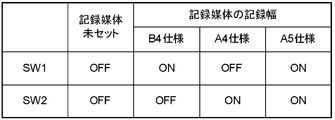
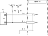
- FIG. 8 is a diagram showing a configuration for detecting the recording width of the recording medium, and is a table showing a correspondence between the on / off state of the switch and the recording width of the recording medium. It is a circuit diagram for detecting the recording width of a recording medium.
- FIG. 2 is a cross-sectional view showing an internal configuration of the image forming apparatus.
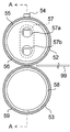
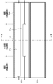
- FIG. 4B is a schematic view showing the internal structure of the fixing unit, and is a cross-sectional view perpendicular to the longitudinal direction of the fixing roller and the pressure roller, and is also a cross-sectional view taken along line BB in FIG. It is AA sectional drawing of FIG.
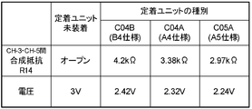
- FIG. 6 is a diagram showing a configuration for detecting the type of fixing unit, and is a table showing a correspondence between the type of fixing unit and a detection voltage.
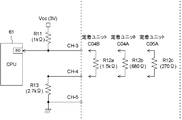
- FIG. 6 is a circuit diagram for detecting the type of fixing unit.
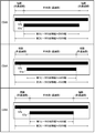
- FIG. 6 is a view showing a combination of heaters incorporated in the fixing roller for each type of fixing unit.
- FIG. 2 is a block diagram showing a configuration related to control of the image forming apparatus.
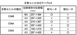
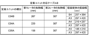
- FIG. 7 is a diagram showing a fixing unit correspondence table in which the type of fixing unit, the recording width of the recording medium, and the selection information of either the first heater or the second heater are associated with each other.
- FIG. 7 is a diagram showing a fixing unit correspondence table in which the types of fixing units, the heating widths of the first heater and the second heater, and the recording widths of the recording medium are associated with each other. 7 is a graph showing transition of the surface temperature of the non-passing portion of the fixing roller.
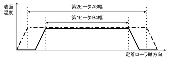
- FIG. 16 is a view showing an image of a surface temperature distribution of a fixing roller when using a first heater having a heating width adapted to the width of B4 or using a second heater having a heating width adapted to the width of A3.
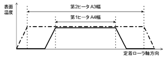
- FIG. 16 is a view showing an image of a surface temperature distribution of a fixing roller when using a first heater having a heating width compatible with the width of A4 or using a second heater having a heating width compatible with the width of A3.
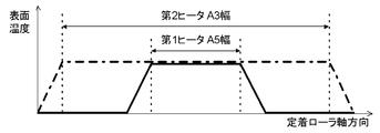
- FIG. 16 is a view showing an image of a surface temperature distribution of a fixing roller when using a first heater having a heating width conforming to the width of A5 or using a second heater having a heating width conforming to the width of A3.
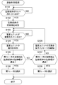
- 6 is a flowchart of a compatibility determination process performed by the printing apparatus according to the first embodiment.
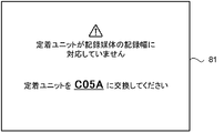
- FIG. 6 is a view showing a message screen notified by the printing apparatus according to the first embodiment.
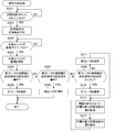
- 15 is a flowchart of a compatibility determination process performed by the printing apparatus according to the second embodiment.
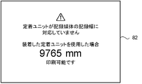
- FIG. 14 is a view showing a message screen notified by the printing apparatus according to the second embodiment. It is a flow chart of conformity distinction processing which a printer concerning a modification of the present invention performs.
- FIG. 1 shows the overall configuration of a printing apparatus according to the first embodiment of the present invention.
- the printing apparatus 100 includes a supply device 10 and an image forming apparatus 20.
- the roll-shaped recording medium 99 is shown as a recording medium for image formation in the first embodiment, the present invention is not limited to this, and a cut-shaped recording medium, a continuous recording medium with pin feed holes, etc. may be used.
- the supply device 10 supplies a roll-shaped recording medium 99 to the image forming apparatus 20.
- the supply device 10 continuously pulls out the recording medium 99 in which the recording medium is wound in a roll around the winding core (tube), and conveys the recording medium 99 to the image forming apparatus 20.
- the supply device 10 internally includes a holding unit (unwinder) 18 and a transport unit 11. Furthermore, the feeding device 10 comprises a rewinder 19 thereon.
- the supply device 10 functions as a supply unit according to the present invention.
- the holding unit 18 holds the recording medium 99.
- the holding unit 18 includes a rotatable rotation shaft (shaft) that holds the recording medium 99 by penetrating the winding core of the recording medium 99, and a support that supports the rotation shaft.
- the holding unit 18 rotatably holds the recording medium 99.
- the holding unit 18 functions as a holding unit according to the present invention.
- the holding unit 18 is mounted with a motor for rotating the rotation shaft.
- the holding unit 18 rotates the rotation shaft at the number of rotations per unit time instructed by the drive of the motor, and unwinds the held recording medium 99 and sends it out to the conveyance unit 11.
- the conveyance unit 11 conveys the recording medium 99 unwound from the holding unit 18 along the conveyance path, and supplies the recording medium 99 to the image forming apparatus 20.
- the transport unit 11 functions as a transport unit according to the present invention.
- the conveyance unit 11 includes a tension roller 12, a driven roller 13, a recording medium setting unit 14, a recording medium conveyance roller pair 15, an auto cutter 16, and a main body entry conveyance roller pair 17.
- the tension roller 12 is installed immediately after the holding portion 18.
- the tension roller 12 controls the recording medium 99 delivered from the holding unit 18 so as not to be slackened.
- the tension roller 12 is installed so as to be movable in the vertical direction, and moves vertically downward by a force such as its own weight or a spring to apply a back tension to the recording medium 99 being conveyed. As a result, the tension (tension) applied to the recording medium 99 is kept constant, and the conveyance of the recording medium 99 is stabilized.
- the driven roller 13 is a roller that follows the conveyance of the recording medium 99 and rotates around a rotation axis whose position is fixed.
- the driven roller 13 is disposed downstream of the tension roller 12 in the conveyance path.
- the driven roller 13 adjusts the conveyance direction of the recording medium 99.
- the recording medium setting unit 14 is a unit prepared for the operator to regulate the supply position of the recording medium 99.
- the recording medium set unit 14 functions as a recording medium setting unit according to the present invention.
- the recording medium setting unit 14 includes a top cover engaged with the unit main body so as to be openable and closable, and a restriction guide for restricting the deviation of the recording medium 99 in the recording width direction.
- the top cover is integrally formed with a member that holds the upper roller of the recording medium conveyance roller pair 15, and is opened and closed by the operator along with the recording medium conveyance roller pair 15.
- the restriction guide is slidably attached to the bottom plate of the main body of the recording medium set unit 14.
- the restriction guide functions as a recording width detection unit of the recording medium 99.
- the recording width means the length of the recording medium 99 in the direction orthogonal to the supply direction (conveying direction).
- the recording medium 99 is unwound from the holding unit 18 by the operator and placed on the bottom plate of the recording medium setting unit 14.
- the operator regulates the transport position of the recording medium 99 by sliding the regulation guide so that the recording medium 99 does not shift in the recording width direction.
- switch elements SW1 and SW2 such as micro switches and reed switches are arranged at the positions of the recording widths of the fixed recording media.
- the on / off of the switch elements SW1 and SW2 is switched according to the slide of the regulation guide.
- FIG. 2A shows on / off of the respective switch elements SW1 and SW2 when the recording medium 99 having the recording width of each fixed recording medium (B4, A4, A5) is regulated by the regulation guide and is not regulated. It is a table which shows a state.
- the image forming apparatus 20 determines which recording width of the fixed recording medium the recording width of the recording medium 99 corresponds to based on the voltage level which changes according to the on / off of the switch elements SW1 and SW2.
- a power supply Vcc1 is connected via a pull-up resistor R1 to a signal line connecting the switch element SW1 and an IN port 1 (IN1) of the CPU 61 of the image forming apparatus 20 described later.
- a power supply Vcc2 is connected to a signal line connecting the switch element SW2 and the IN port 2 (IN2) of the CPU 61 via a pull-up resistor R2.
- the switch element SW1 and the switch element SW2 are connected by an earth wire whose one end is grounded to the ground level.
- the switch elements SW1 and SW2 are both in the OFF state.
- the IN ports IN1 and IN2 of the CPU 61 are pulled up to an H (high) level voltage (3 V).
- the switch element SW1 is off and the switch element SW2 is on. It will be in the state of In this case, the IN port IN1 of the CPU 61 is pulled up, and a high (H) level voltage (3 V) is applied.
- the IN port IN2 of the CPU 61 is directly connected to the ground, and a low (L) level voltage (0 V) is applied.
- the CPU 61 detects the size (recording width) of the recording medium 99 set in the recording medium set unit 14 based on the change of the applied voltage.
- the recording medium conveyance roller pair 15 conveys the recording medium 99 set by the recording medium setting unit 14 to the subsequent conveyance mechanism.
- the recording medium conveyance roller pair 15 is driven by a motor to sandwich the recording medium 99 set in the recording medium setting unit 14 and supplies the recording medium 99 to the auto cutter 16 and the main body entering conveyance roller pair 17.
- the auto cutter 16 finishes conveying the recording medium 99 having a length necessary for the process performed in the image forming apparatus 20, the auto cutter 16 cuts the end thereof.
- the main body entry transport roller pair 17 transports the recording medium 99 cut by the automatic cutter 16 to the image forming apparatus 20.
- the main body entry conveyance roller pair 17 is driven by a motor, and nips and conveys the recording medium 99 supplied from the recording medium conveyance roller pair 15 and supplies the recording medium 99 to the image forming apparatus 20.
- the take-up unit 19 installed on the supply device 10 takes up and holds the recording medium 99 discharged from the image forming apparatus 20. Similar to the holding unit 18, the winding unit 19 penetrates the winding core (tube) of the recording medium 99 to hold the recording medium 99, and a support table that supports the winding axis. And consists of The winding unit 19 rotatably holds the recording medium 99.
- a motor for rotating the winding shaft is mounted on the winding unit 19.
- the winding unit 19 rotates the winding shaft at the instructed number of rotations per unit time.
- the winding unit 19 winds up the recording medium 99 delivered from the image forming apparatus 20 via the driven roller 21.
- the image forming apparatus 20 is disposed on the top surface of the supply device 10.
- the image forming apparatus 20 forms an image on the recording medium 99 supplied from the supply device 10.
- the image forming apparatus 20 is, for example, a label printer.
- the image forming apparatus 20 continuously performs image formation of image data covering a relatively large area on the recording medium 99 continuously supplied from the supply device 10.
- the image forming apparatus 20 includes an image forming unit 30, an intermediate transfer belt unit 40, and a fixing unit 50.
- the image forming unit 30 has a configuration in which four image forming units 31 (31k, 31c, 31m, 31y) are installed in series. Of the four image forming units 31, three image forming units 31c, 31m, and 31y on the upstream side (right side in FIG. 3) are cyan (C), magenta (M), and yellow (subtractive three primary colors), respectively. A color image is formed by the Y) color toner. On the other hand, the image forming unit 31k on the downstream side (left side in FIG. 3) forms a monochrome image with black (K) toner mainly used for characters and dark portions of images.
- K black
- Each image forming unit 31 includes a photosensitive drum 32 at the lower part.
- the circumferential surface of the photosensitive drum 32 is made of, for example, an organic photoconductive material.
- the cleaner 33, the charging roller 34, the optical writing head 35, and the developing roller 37 of the developing device 36 are disposed so as to surround the circumferential surface.
- the developing device 36 has a toner container at the top, which accommodates any one of black (K), cyan (C), magenta (M) and yellow (Y) toner.
- the developing device 36 has a toner replenishment mechanism at an intermediate portion.
- the developing device 36 includes the above-described developing roller 37 at the side opening.
- the developing device 36 further includes a toner stirring member inside.
- the developing roller 37 includes a toner supply roller that supplies toner, a doctor blade that regulates the toner layer on the developing roller 37 to a constant layer thickness, and the like.
- each image forming unit 31 has the same configuration except for the color of the toner stored in the toner container.
- the intermediate transfer belt unit 40 includes an endless transfer belt 41, a drive roller 42, and a driven roller 43.
- the transfer belt 41 extends in the form of a flat loop substantially at the center of the inside of the image forming apparatus 20 and from the almost end to the end shown in FIG.
- the driving roller 42 circulates the transfer belt 41 shown in FIG. 3 in the counterclockwise direction.
- the transfer belt 41 transports the recording medium 99 to the transfer position in order to transfer the toner image directly transferred (primary transfer) to the belt surface to the recording medium 99 (secondary transfer).
- the intermediate transfer belt unit 40 includes four primary transfer rollers 44 in a loop of the transfer belt 41.
- Each primary transfer roller 44 corresponds to the image forming units 31k, 31c, 31m, and 31y.
- the primary transfer roller 44 is formed of a conductive foam sponge for pressing the lower circumferential surface of the photosensitive drum 32 through the transfer belt 41.
- the primary transfer roller 44 rotates at a designated rotation cycle to bring the transfer belt 41 into contact with the photosensitive drum 32 or to separate from the photosensitive drum 32.
- the standby conveyance roller pair 45 receives the recording medium 99 conveyed from the supply device 10.
- the standby conveyance roller pair 45 conveys the received recording medium 99 to the secondary transfer roller 46.
- the secondary transfer roller 46 is disposed in pressure contact with the driven roller 43 via the transfer belt 41.
- the secondary transfer roller 46 secondarily transfers the toner image transferred to the belt surface of the transfer belt 41 to the recording medium 99.
- the secondary transfer roller 46 functions as a transfer unit according to the present invention.
- the fixing unit 50 is disposed downstream of the secondary transfer roller 46 in the conveyance direction of the recording medium 99 (upward in FIG. 3).
- the fixing unit 50 heats and melts the toner transferred to the recording medium 99, and causes the toner to which pressure is applied to penetrate the recording medium 99.
- the toner image is fixed to the recording medium 99.
- the fixing unit 50 stores the fixing unit 51.
- the fixing unit 51 is removable from the image forming apparatus 20.
- the fixing unit 51 functions as a fixing unit storage unit according to the present invention.
- the operator replaces the fixing unit 51 as needed.
- the fixing unit 51 is classified into a plurality of types according to the overheat width of a first heater 57a described later.
- the operator mounts a fixing unit of the corresponding type according to the recording width of the recording medium 99 set in the recording medium set unit 14.
- the fixing unit 51 includes a fixing roller 52, a pressure roller 53, and a thermistor 54.
- the fixing roller 52 heats the toner transferred to the recording medium 99.
- the fixing roller 52 as shown in FIG. 4A, is composed of a core metal portion 55 of a cylindrical body and an elastic layer 56.
- the metal core 55 is made of metal.
- the elastic layer 56 is made of silicone rubber or the like covering the outer surface of the cored bar 55.
- the cored bar portion 55 is formed in a hollow shape, and the heater 57 which is a heating portion is built in the cored bar portion 55.
- the fixing roller 52 is heated by radiant heat from the heater 57 to a temperature necessary for melting the toner.
- the fixing roller 52 incorporates a first heater 57a and a second heater 57b which have different axial lengths.
- the first heater 57a has a heating width capable of heating the recording medium 99 having a length substantially equal to any of the recording widths A4, B4, and A5.
- the second heater 57b has a heating width capable of heating the recording medium 99 having a length substantially equal to the recording width of A3.
- the CPU 61 selects which of the first heater 57a and the second heater 57b is to be used according to the recording width of the recording medium 99 set in the recording medium set unit 14, supplies power to the selected heater 57, and fixes.
- the roller 52 is heated.
- the number of heaters 57 incorporated in the fixing roller 52 is not limited to two, and may be three or more.
- the fixing roller 52 is divided into a central portion (passing portion) through which the recording medium 99 passes and an end portion (non-passing portion) through which the recording medium 99 does not pass.
- the central portion and the end portion change in accordance with the recording width of the recording medium 99.
- FIG. 4B shows a central portion and an end portion divided when printing a recording medium 99 having a recording width compatible with the heating width of the first heater 57a.
- the heating width of the heater 57 and the recording width of the recording medium 99 are compatible, the heating width of the heater 57 is slightly wider than the recording width of the recording medium 99, and the difference between them is about 10 mm. means.
- the pressure roller 53 is a pressure member.
- the pressure roller 53 presses the toner in the molten state to the recording medium 99 by the heating of the fixing roller 52.
- the toner image is fixed to the recording medium 99.
- the pressure roller 53 as shown in FIG. 4A, comprises a cored bar portion 58 of a cylindrical body and an elastic layer 59.
- the cored bar portion 58 is made of metal.
- the elastic layer 59 is made of silicon rubber or the like and covers the outer surface of the cored bar 58.
- the pressure roller 53 is disposed to face the fixing roller 52.
- the pressure roller 53 is elastically supported by an elastic body such as a spring.
- the pressure roller 53 biases the fixing roller 52 to apply a constant pressure.
- a sandwiching portion in which a constant pressure is secured is formed.
- the passing recording medium 99 is heated and pressurized, and the toner image is fixed to the recording medium 99.
- a heater may be disposed on the pressure roller 53 to control the temperature of the pressure roller 53.
- thermistors 54a and 54b are disposed at positions facing and approaching the center portion and one side end portion of the fixing roller 52, respectively.
- the thermistors 54a and 54b function as part of a temperature sensor that detects the temperature of the outer peripheral surface of the fixing roller 52, as shown in FIG. 4B.
- the power supply to the heater 57 incorporated in the fixing roller 52 is controlled in accordance with the temperature detected by the thermistors 54a and 54b.
- the fixing unit 51 is divided into a plurality of types as shown in FIG. 6 by the combination of the heating widths of the first heater 57 a and the second heater 57 b built in the fixing roller 52.
- the first heater 57a has a heating width substantially equal to the recording widths of B4, A4, and A5.
- the second heater 57b has a heating width substantially equal to the recording width of B3, which is the largest printable recording medium.
- the fixing unit 51 is divided into three types for explanation. However, the number of types is not limited to this, and the fixing unit 51 of the fixing unit 51 corresponds to the recording width of a larger number of recording media. The type may be set. Further, the heating widths of the second heaters 57b may be different from each other.
- the fixing unit 51 includes resistance elements R12 of different resistance values according to the type divided by the heating width of the first heater 57a.
- fixing units of types C04B, C04A, and C05A each include resistive elements R12a, R12b, and R12c. Resistance values of the resistance elements R12a, R12b, and R12c are 1.5 k ⁇ , 680 ⁇ , and 270 ⁇ , respectively.
- FIG. 5A is a table showing a combined resistance R14 of the resistance element R12 and the pull-down resistance R13 provided in the supply device 10, and a voltage value applied to the IN port 3 (IN3) of the CPU 61.
- the fixing unit 51 when the fixing unit 51 is attached to the image forming apparatus 20, the voltage division ratio between the pull-up resistor R11 and the combined resistance R14 of the resistor element R12 and the pull-down resistor R13 is the fixing unit 51 (resistor element R12) attached. Change according to the type of Therefore, the voltage level applied to the IN port 3 (IN3) of the image forming apparatus 20 also changes according to the type of the fixing unit 51 attached.
- the image forming apparatus 20 can determine the type of the attached fixing unit 51 by detecting the voltage level applied to the IN port 3.
- the resistance value of the combined resistance R14 of the resistance (270 ⁇ ) of the fixing unit 51 and the pull-down resistance (2.7 k ⁇ ) of the image forming apparatus 20. Is 2.97 k ⁇ .
- the voltage applied to the IN port 3 of the image forming apparatus 20 is 2.24 V because it is a divided voltage of the pull-up resistor R11 (1 k ⁇ ) and the combined resistor R14.
- the image forming apparatus 20 detects the type of the attached fixing unit 51 based on the applied voltage.
- the resistance element provided in the fixing unit 51 is not limited to one connected to CH-3 and CH-4.
- the resistive element included in the fixing unit 51 may be configured to connect CH-3 and CH-4 and connect in parallel with the pull-down resistor R13.
- the type of the fixing unit 51 can be determined by the voltage value applied to the CPU 61.
- a discharge roller pair 22 is disposed further downstream of the fixing unit 50.
- the discharge roller pair 22 carries out from the fixing unit 50 the recording medium 99 on which the toner image is fixed.
- the discharge roller pair 22 discharges the recording medium 99 to a discharge tray formed on the upper surface of the image forming apparatus 20.
- the recording medium 99 discharged through the discharge roller pair 22 is supplied to the winding unit 19 via a driven roller 21 installed on the side of the image forming apparatus 20.
- the image forming apparatus 20 is connected to the host computer 80 and the supply device 10 by a network such as a local area network (LAN) or a universal serial bus (USB).
- a network such as a local area network (LAN) or a universal serial bus (USB).
- the image forming apparatus 20 includes a control unit 60 and a printing unit 70. More specifically, the control unit 60 includes a CPU 61, a LAN communication unit 62, a USB communication unit 63, a panel control unit 64, an operation panel 65, a storage device 66, a storage device control unit 67, and a command analysis unit 68.
- the printing unit 70 further includes a printing control unit 71 and a printing mechanism unit 72.
- the CPU 61 is connected to each unit of the image forming apparatus 20 via a system bus which is a transmission path for transferring an instruction and data, and controls the operation of each unit of the image forming apparatus 20.
- the CPU 61 uses a read only memory (ROM) and a random access memory (RAM) as a work memory, reads various programs such as system software stored in the ROM and the storage device 66, and appropriately executes the programs. Further, a signal (temperature signal) representing the temperature measured by the thermistors 54a and 54b is supplied to the CPU 61.
- ROM read only memory
- RAM random access memory
- the LAN communication unit 62 and the USB communication unit 63 communicate with an external device.
- the LAN communication unit 62 communicates via the LAN.
- the USB communication unit 63 performs communication via USB.
- the CPU 61 communicates with the host computer 80 via the LAN communication unit 62 or the USB communication unit 63.
- the CPU 61 receives the print job transmitted from the host computer 80 via the LAN communication unit 62 or the USB communication unit 63. Further, the CPU 61 transmits various information of the image forming apparatus 20 to the host computer 80 via the LAN communication unit 62 or the USB communication unit 63. Further, the CPU 61 communicates with the supply device 10 via the LAN communication unit 62 or the USB communication unit 63.
- the CPU 61 receives an output signal from a detection element (sensor) disposed in the recording medium set unit 14 and detects the recording width of the recording medium 99 based on the received output signal.
- the panel control unit 64 is connected to the operation panel 65.
- the operation panel 65 includes, for example, a display panel such as an LCD (Liquid Crystal Display) and an input device such as various operation buttons.
- the panel control unit 64 displays various images, characters, symbols, and the like on the operation panel 65 under the control of the CPU 61.
- panel control unit 64 receives various operations from the user input to operation panel 65.
- the panel control unit 64 supplies the CPU 61 with operation signals respectively corresponding to the received various operations.
- Operation panel 65 may be a device in which an input function and a display function are combined, such as a touch panel (touch screen) having a touch switch function.
- the storage device 66 is configured of, for example, a non-volatile memory such as an EEPROM (Electrically Erasable Programmable ROM) or an HDD (Hard Disc Drive).
- EEPROM Electrically Erasable Programmable ROM
- HDD Hard Disc Drive
- the storage device 66 stores a fixing unit correspondence table A as shown in FIG. 8A.
- the type of the fixing unit 51 the recording width of the recording medium, and the selection information of either the first heater 57a or the second heater 57b are associated.
- the type of the fixing unit 51 is classified according to the heating width of the first heater 57 a built in the fixing roller 52.
- the recording width of the recording medium indicates the recording width (width ⁇ length) of the fixed recording medium adapted to the heating width of the first heater 57a.
- the selection information of the heater 57 is information indicating which of the first heater 57a and the second heater 57b can be selected.
- the storage device 66 also stores a fixing unit correspondence table B as shown in FIG. 8B.
- the type of the fixing unit 51, the heating width of the first heater 57a and the heating width of the second heater 57b, and the recording width of the recording medium are associated.
- the type of the fixing unit 51 is classified according to the heating width of the first heater 57a.
- the heating width of the first heater 57a is about 10 mm wider than any one of the recording widths A4, B4 and A5, and covers the entire recording width of each recording medium.
- the recording width of the recording medium indicates the recording width (width ⁇ length) of the fixed recording medium adapted to the heating width of the first heater 57a.
- the storage device control unit 67 controls writing of data to the storage device 66 and reading of data stored in the storage device 66 under the control of the CPU 61.
- the command analysis unit 68 analyzes commands included in the print data transmitted from the host computer 80 under the control of the CPU 61.
- the command analysis unit 68 converts print data into bitmap image data for each of black (K), magenta (M), cyan (C), and yellow (Y).
- the command analysis unit 68 develops the converted bitmap image data in the corresponding storage area of the frame memory for each of black (K), magenta (M), cyan (C), and yellow (Y).
- the image data expanded in the frame memory is output to the print control unit 71.
- the print control unit 71 controls the print mechanism unit 72 including the image forming unit 30, the intermediate transfer belt unit 40, and the fixing unit 50 under the control of the CPU 61.
- the print control unit 71 performs print processing in accordance with the image data generated by the command analysis unit 68. For example, the print control unit 71 vertically moves the intermediate transfer belt unit 40, rotationally drives the transfer belt 41, the drive roller 42, the standby conveyance roller pair 45, the discharge roller pair 22 and the like, and applies voltage to the rotation drive system and the like. Control of voltage application and the like to the heater 57 and the like of the fixing unit 50 is performed.
- the transition of the surface temperature of the end portion (non-passing portion) of the fixing roller 52 through which the recording medium 99 does not pass will be described.
- the CPU 61 When the power of the image forming apparatus 20 is turned on, the CPU 61 outputs the heater 57 at maximum power until the temperature detected by the thermistor 54a reaches a target temperature Tt (for example, 180.degree. C.) which is a temperature necessary for melting the toner. Heat up.
- the CPU 61 performs feedback control of the amount of heat generation of the heater 57 so that the target temperature Tt is maintained.
- PID Proportional Integral Derivative
- the surface temperature of the central portion (passing portion) of the fixing roller 52 through which the recording medium 99 passes is substantially maintained at the target temperature Tt by PID control.
- the surface temperature of the end (non-passing portion) of the fixing roller 52 through which the recording medium 99 does not pass is higher than that of the central portion (passing portion) because heat is stored without taking heat by the recording medium 99.
- the surface temperature of the end portion of the fixing roller 52 is increased until the target temperature Tt is reached after the power of the image forming apparatus 20 is turned on, as in the central portion.
- the CPU 61 starts the printing operation after the temperatures detected by the thermistors 54a and 54b reach the target temperature Tt.
- the surface temperature of the end portion of the fixing roller 52 gradually increases even after the printing operation is started.
- the CPU 61 stops the power supply to the heater 57 in the fixing roller 52 to interrupt the printing operation. .
- the CPU 61 When the surface temperature of the end portion of the fixing roller 52 falls to the lower limit temperature Tm (for example, 175 ° C.) necessary for melting of the toner, the CPU 61 starts power supply to the heater 57 to restart the printing operation. As described above, the CPU 61 instructs the stop and restart of the printing operation according to the change of the surface temperature of the end.
- the values of the target temperature Tt, the lower limit temperature Tm, and the threshold Tth are stored in advance in, for example, an EEPROM or an HDD.
- FIGS. 10A to 10C show the surface temperature distribution of the fixing roller 52 when the first heater 57a having a heating width adapted to the widths B4, A4, and A5 is used, respectively.
- the broken line in FIG. 10A to FIG. 10C shows the surface temperature distribution of the fixing roller 52 in the case of continuous printing using the second heater 57b having a heating width adapted to the width of A3.
- the surface temperature of the fixing roller 52 is high in the heating width of the first heater 57a, but the outside thereof Decline as you head Similarly, when the fixing roller 52 is heated using the second heater 57b, the surface temperature of the fixing roller 52 is high at the heating width of the second heater 57b, but decreases toward the outside thereof.
- the end portion (non-passing portion) of the fixing roller 52 through which the recording medium 99 does not pass As described above, if continuous printing is performed using the fixing unit 51 having the heater 57 having a heating width that matches the recording width of the recording medium 99, the end portion (non-passing portion) of the fixing roller 52 through which the recording medium 99 does not pass. The temperature does not rise above the central portion (passing portion) through which the recording medium 99 passes. Therefore, the surface temperature of the end portion of the fixing roller 52 is less likely to be overheated.
- the CPU 61 of the image processing apparatus 20 starts the process shown in FIG. 11 in response to the print command being input and the print job being generated.
- the CPU 61 functions as a compatibility determination unit according to the present invention.
- the CPU 61 determines whether the recording medium 99 is set in the recording medium set unit 14 (step S101). When the recording medium 99 is set and the top cover of the recording medium setting unit 14 is closed, an output signal of an appropriate sensor is transmitted to the image forming apparatus 20 via the communication unit included in the supply device 10. When the CPU 61 receives an output signal from the supply device 10, the CPU 61 determines that the recording medium 99 is set in the recording medium set unit 14.
- the CPU 61 determines that the recording medium 99 is set in the recording medium set unit 14 (step S101; YES).
- the CPU 61 determines the recording width of the recording medium 99 (step S102).
- the CPU 61 determines the size (recording width) of the recording medium 99 based on the voltage values applied to the IN port 1 and the IN port 2.
- the CPU 61 functions as a recording medium type reading unit according to the present invention.
- step S101 when the CPU 61 receives no output signal from the supply device 10, it determines that the recording medium 99 is not set in the recording medium set unit 14 (step S101; NO). In this case, the CPU 61 returns to step S101. That is, the CPU 61 repeats the process of step S101 until it determines that the recording medium 99 is set in the recording medium set unit 14 (until the output signal is received from the supply device 10).
- the CPU 61 determines whether the fixing unit 51 is attached to the image forming apparatus 20 (step S103). The CPU 61 determines whether the fixing unit 51 is attached based on the voltage value applied to the IN port 3.
- the CPU 61 determines the type of the fixing unit 51 (step S104).
- the CPU 61 determines the heating width of the fixing unit 51 based on the voltage value applied to the IN port 3 as in the process of step S103.
- the CPU 61 functions as a fixing unit type reading unit according to the present invention.
- step S103 when determining that the fixing unit 51 is not attached (step S103; NO), the CPU 61 returns the process to step S103 and stands by until the fixing unit 51 is attached.
- the CPU 61 determines whether the heating width of the first heater 57a specified by the type of the fixing unit 51 matches the recording width of the recording medium 99 (step S105).
- the CPU 61 refers to the fixing unit correspondence table A stored in the storage device 66 and determines the size (recording width) of the recording medium 99 determined in step S102 and the type of the fixing unit 51 determined in step S104. Search for correspondence. Thus, it is determined whether the heating width of the first heater 57a and the recording width of the recording medium 99 are suitable.
- the CPU 61 determines that the heating width of the first heater 57a matches the recording width of the recording medium 99 (step S105; YES)
- the CPU 61 selects the first heater 57a as the heater 57 to be used and ends the processing (step S106).
- the CPU 61 may notify a message that the type of the mounted fixing unit 51 matches the recording width of the recording medium 99 set in the recording medium set unit 14 before the processing is completed.
- the CPU 61 functions as a message notification unit according to the present invention.
- the CPU 61 determines that the heating width of the first heater 57a and the recording width of the recording medium 99 do not match (step S105; NO), the heating width of the second heater 57b and the recording width of the recording medium 99 match. It is determined whether or not (step S107).
- the CPU 61 refers to the fixing unit correspondence table B shown in FIG. 8B, and determines that the difference is 10 mm or less if the difference between the overheat width of the second heater 57b and the width of the recording width of the recording medium 99 is 10 mm or less.
- step S107 When the CPU 61 determines that the heating width of the second heater 57b matches the recording width of the recording medium 99 (step S107; YES), the CPU 61 selects the second heater 57b as the heater 57 to be used and ends the processing (step S108).
- the recording medium 99 is referred to the fixing unit correspondence table B shown in FIG.
- the heater 57 having a heating width that matches the recording width of the image is searched.
- the CPU 61 specifies the type of the fixing unit 51 based on the search result.
- the CPU 61 controls the panel control unit 64 to display a message prompting the user to replace the mounted fixing unit 51 with a fixing unit 51 of a type corresponding to the recording width of the recording medium 99 as shown in FIG.
- the operation panel 65 is displayed (step S109).
- step S109 the CPU 61 returns the process to step S103, and repeats the processes of steps S103 to S105. That is, the CPU 61 causes the operation panel 65 to display the message screen 81 shown in FIG. 12 until either the first heater 57a or the second heater 57b is selected as the heater 57 to be used.
- the print job generated according to the print command received from the host computer 80 is executed.
- the print job is executed under the condition that the fixing unit 51 corresponding to the recording width of the set recording medium 99 is attached to the image forming apparatus 20. Ru.
- printing is performed using the heater 57 having a heating width substantially equal to the recording width of the recording medium 99, so that the temperature of the end portion of the fixing roller 52 is prevented from being overheated by exceeding the threshold Tth. it can.
- the printing apparatus 100 When the recording width of the recording medium 99 does not match the heating widths of the first heater 57a and the second heater 57b, the printing apparatus 100 according to the first embodiment notifies a message prompting replacement of the fixing unit 51. However, it is also assumed that continuous printing can not be avoided under the condition that the fixing unit 51 corresponding to the recording width of the recording medium 99 can not be prepared.
- Steps S201 to S208 in the flowchart of FIG. 13 are the same processes as steps S101 to S108 in the flowchart of FIG.
- step S205 After the CPU 61 determines the recording width of the recording medium 99 and the type of the fixing unit 51 by the processes of steps S201 to S204, the heating width of the first heater 57a specified by the type of the fixing unit 51 and the recording of the recording medium 99 It is determined whether or not the width matches (step S205). If the CPU 61 determines that it does not fit (step S205; NO), it determines whether the heating width of the second heater 57b matches the recording width of the recording medium 99 set in the recording medium set unit 14 (step S205) Step S207).
- step S 207 If the CPU 61 determines that the heating width of the second heater 57 b does not match the recording width of the recording medium 99 (step S 207; NO), whether the heating width of the first heater 57 a is wider than the recording width of the recording medium 99 It is determined whether or not it is (step S209). This is to avoid the problem that a part of the toner image can not be fixed to the recording medium 99 due to the insufficient heating width of the first heater 57a.
- the CPU 61 determines that the heating width of the first heater 57a is wider than the recording width of the recording medium 99 (step S209; YES)
- the CPU 61 selects the first heater 57a as the heater 57 to be used (step S210). Thereafter, the CPU 61 can print the recording medium 99 before the temperature of a predetermined portion of the fixing unit 51, here, the end of the fixing roller 52 (the portion where the temperature is measured by the thermistor 54b) exceeds the threshold Tth.
- Amount (length, number of sheets) is acquired (step S212). That is, the printable amount is determined without thermally damaging the fixing unit 51.
- the amount of printable recording medium 99 takes into consideration the temperature rise characteristics of the fixing roller 52.
- the time at which the temperature of the end portion of the fixing roller 52 exceeds the threshold Tth is calculated, and the amount of printable recording medium 99 is calculated by that time.
- the amount of printable recording medium may be determined in advance by experiment, and may be stored in, for example, an EEPROM or an HDD.
- the CPU 61 functions as a recording medium amount acquisition unit according to the present invention.
- the CPU 61 controls the panel control unit 64 to display a message screen 82 as shown in FIG. 14 on the operation panel 65 (step S213).
- the message screen 82 shows a message indicating that the fixing unit 51 loaded is not compatible with the recording width of the recording medium 99, and the amount of the printable recording medium 99. Thus, the operator can know the amount of recording media 99 that can be printed before the printing operation is interrupted.
- the CPU 61 ends the conformity determination process.
- step S209 when determining that the heating width of the first heater 57a is narrower than the recording width of the recording medium 99 (step S209; NO), the CPU 61 selects the second heater 57b as the heater 57 to be used (step S211). When the process of step S211 is completed, the CPU 61 shifts the process to step S212.
- the heating width of the first heater 57a incorporated in the mounted fixing unit 51 is the recording width of the recording medium 99 set in the recording medium set unit 14.
- the first heater 57a is used when the distance is wider.
- the amount of printable recording medium 99 is acquired and notified before the temperature of the end portion of the fixing roller 52 not passing the recording medium 99 exceeds the threshold.
- the operator can confirm the amount of printable recording medium 99 in advance, and can select the print content in accordance with the amount of recording medium 99. This can prevent a decrease in printing efficiency.
- the fixing unit 51 including the fixing roller 52, the pressure roller 53, and the thermistor 54 has been described as an example.
- the configuration of the fixing unit 51 is not limited to this, and a so-called belt fixing method in which a heating roller incorporating a heater and a fixing belt stretched between the fixing roller and the heating roller is added instead of the fixing roller. It may be In this case, a central portion (passing portion) and an end portion (non-passing portion) are formed on the fixing belt and the fixing roller, but by adjusting the heating width of the heater inside the heating roller which is a heating source, The same effect as that of the embodiment can be obtained.
- the heating width of the first heater 57a Whether or not the recording width of the recording medium 99 is wider is determined, and the first heater 57a or the second heater 57b is selected according to the determination result.
- the first heater 57a or the second heater 57b may be selected if it is determined that there is an instruction to use (step S314) and this instruction is determined (step S314; YES) (step S314).
- the application method of such a program is arbitrary.
- the program can be stored in a computer-readable storage medium such as, for example, a flexible disk, a CD (Compact Disc) -ROM, a DVD (Digital Versatile Disc) -ROM, a memory card, and the like.
- the program can be superimposed on a carrier wave and applied via a communication medium such as the Internet.
- the program may be posted and distributed in a bulletin board (BBS: Bulletin Board System) on a communication network.
- BSS Bulletin Board System
- the program may be activated and executed in the same manner as other application programs under the control of an OS (Operating System) to execute the above process.
- OS Operating System
Landscapes
- Physics & Mathematics (AREA)
- General Physics & Mathematics (AREA)
- Engineering & Computer Science (AREA)
- Microelectronics & Electronic Packaging (AREA)
- Control Or Security For Electrophotography (AREA)
- Color Electrophotography (AREA)
- Fixing For Electrophotography (AREA)
- Electrophotography Configuration And Component (AREA)
Priority Applications (2)
| Application Number | Priority Date | Filing Date | Title |
|---|---|---|---|
| US14/917,266 US20160216653A1 (en) | 2013-09-20 | 2014-09-12 | Printing device and printing control method |
| CN201480032388.1A CN105308512A (zh) | 2013-09-20 | 2014-09-12 | 印刷装置、印刷控制方法及程序 |
Applications Claiming Priority (2)
| Application Number | Priority Date | Filing Date | Title |
|---|---|---|---|
| JP2013-196095 | 2013-09-20 | ||
| JP2013196095A JP2015060208A (ja) | 2013-09-20 | 2013-09-20 | 印刷装置、印刷制御方法及びプログラム |
Publications (1)
| Publication Number | Publication Date |
|---|---|
| WO2015041180A1 true WO2015041180A1 (ja) | 2015-03-26 |
Family
ID=52688830
Family Applications (1)
| Application Number | Title | Priority Date | Filing Date |
|---|---|---|---|
| PCT/JP2014/074288 Ceased WO2015041180A1 (ja) | 2013-09-20 | 2014-09-12 | 印刷装置、印刷制御方法及びプログラム |
Country Status (4)
| Country | Link |
|---|---|
| US (1) | US20160216653A1 (enExample) |
| JP (1) | JP2015060208A (enExample) |
| CN (1) | CN105308512A (enExample) |
| WO (1) | WO2015041180A1 (enExample) |
Cited By (1)
| Publication number | Priority date | Publication date | Assignee | Title |
|---|---|---|---|---|
| CN107850866A (zh) * | 2015-07-20 | 2018-03-27 | 利盟国际有限公司 | 用于电子照相成像设备的定影组件的加热器构件 |
Families Citing this family (13)
| Publication number | Priority date | Publication date | Assignee | Title |
|---|---|---|---|---|
| JP6203305B2 (ja) * | 2015-05-08 | 2017-09-27 | キヤノン株式会社 | 画像形成装置 |
| EP3098665B1 (en) | 2015-05-08 | 2021-03-10 | Canon Kabushiki Kaisha | Image forming apparatus |
| JP6558070B2 (ja) * | 2015-05-19 | 2019-08-14 | コニカミノルタ株式会社 | 画像形成装置 |
| JP6142906B2 (ja) | 2015-09-28 | 2017-06-07 | カシオ計算機株式会社 | 除電装置及び画像形成システム |
| JP6614966B2 (ja) | 2015-12-25 | 2019-12-04 | キヤノン株式会社 | 画像形成装置 |
| JP2019020655A (ja) * | 2017-07-20 | 2019-02-07 | 株式会社東芝 | 画像形成装置、及び制御方法 |
| JP7114243B2 (ja) * | 2017-11-27 | 2022-08-08 | キヤノン株式会社 | 画像形成装置 |
| US10848625B1 (en) * | 2019-05-10 | 2020-11-24 | Kyocera Document Solutions Inc. | Heat detection system for monitoring of over-heating in an apparatus |
| JP7287179B2 (ja) * | 2019-08-19 | 2023-06-06 | ブラザー工業株式会社 | プログラム |
| JP7409862B2 (ja) * | 2019-12-19 | 2024-01-09 | 東芝テック株式会社 | 画像形成装置及び画像定着方法 |
| JP7528497B2 (ja) * | 2020-03-27 | 2024-08-06 | 富士フイルムビジネスイノベーション株式会社 | 媒体搬送装置および画像形成装置 |
| US12242217B2 (en) | 2022-02-28 | 2025-03-04 | Canon Kabushiki Kaisha | Image forming system, image forming apparatus, and fixing device |
| JP2023125553A (ja) * | 2022-02-28 | 2023-09-07 | キヤノン株式会社 | 画像形成システム及び画像形成装置 |
Citations (8)
| Publication number | Priority date | Publication date | Assignee | Title |
|---|---|---|---|---|
| JPH09305061A (ja) * | 1996-05-17 | 1997-11-28 | Ricoh Co Ltd | 画像形成装置の定着装置及び熱定着方法 |
| JPH10143006A (ja) * | 1996-11-14 | 1998-05-29 | Fuji Xerox Co Ltd | 定着装置 |
| JP2004246083A (ja) * | 2003-02-14 | 2004-09-02 | Seiko Epson Corp | 定着装置及び画像形成装置 |
| JP2007188032A (ja) * | 2005-09-12 | 2007-07-26 | Sharp Corp | 画像形成装置および画像形成装置の設定方法 |
| JP2008058365A (ja) * | 2006-08-29 | 2008-03-13 | Konica Minolta Business Technologies Inc | 画像形成装置 |
| JP2012068560A (ja) * | 2010-09-27 | 2012-04-05 | Konica Minolta Business Technologies Inc | 画像形成装置および画像形成システム |
| JP2012234016A (ja) * | 2011-04-28 | 2012-11-29 | Fuji Xerox Co Ltd | 画像処理装置及び画像形成装置 |
| JP2013254035A (ja) * | 2012-06-05 | 2013-12-19 | Fuji Xerox Co Ltd | 画像形成装置 |
Family Cites Families (5)
| Publication number | Priority date | Publication date | Assignee | Title |
|---|---|---|---|---|
| US5568229A (en) * | 1995-06-21 | 1996-10-22 | Xerox Corporation | Fuser temperature control as a function of copy sheet characteristics |
| JPH09166937A (ja) * | 1995-12-15 | 1997-06-24 | Fuji Photo Film Co Ltd | ロール紙用記録装置 |
| CA2262852A1 (en) * | 1998-06-01 | 1999-12-01 | Nitto Kogyo Co., Ltd. | Toner image fixing apparatus capable of keeping constant fixing roller temperature |
| JP4416801B2 (ja) * | 2007-01-29 | 2010-02-17 | キヤノン株式会社 | 情報処理装置及び情報処理方法 |
| JP5671848B2 (ja) * | 2010-06-23 | 2015-02-18 | 富士ゼロックス株式会社 | 画像形成装置 |
-
2013
- 2013-09-20 JP JP2013196095A patent/JP2015060208A/ja active Pending
-
2014
- 2014-09-12 CN CN201480032388.1A patent/CN105308512A/zh active Pending
- 2014-09-12 WO PCT/JP2014/074288 patent/WO2015041180A1/ja not_active Ceased
- 2014-09-12 US US14/917,266 patent/US20160216653A1/en not_active Abandoned
Patent Citations (8)
| Publication number | Priority date | Publication date | Assignee | Title |
|---|---|---|---|---|
| JPH09305061A (ja) * | 1996-05-17 | 1997-11-28 | Ricoh Co Ltd | 画像形成装置の定着装置及び熱定着方法 |
| JPH10143006A (ja) * | 1996-11-14 | 1998-05-29 | Fuji Xerox Co Ltd | 定着装置 |
| JP2004246083A (ja) * | 2003-02-14 | 2004-09-02 | Seiko Epson Corp | 定着装置及び画像形成装置 |
| JP2007188032A (ja) * | 2005-09-12 | 2007-07-26 | Sharp Corp | 画像形成装置および画像形成装置の設定方法 |
| JP2008058365A (ja) * | 2006-08-29 | 2008-03-13 | Konica Minolta Business Technologies Inc | 画像形成装置 |
| JP2012068560A (ja) * | 2010-09-27 | 2012-04-05 | Konica Minolta Business Technologies Inc | 画像形成装置および画像形成システム |
| JP2012234016A (ja) * | 2011-04-28 | 2012-11-29 | Fuji Xerox Co Ltd | 画像処理装置及び画像形成装置 |
| JP2013254035A (ja) * | 2012-06-05 | 2013-12-19 | Fuji Xerox Co Ltd | 画像形成装置 |
Cited By (3)
| Publication number | Priority date | Publication date | Assignee | Title |
|---|---|---|---|---|
| CN107850866A (zh) * | 2015-07-20 | 2018-03-27 | 利盟国际有限公司 | 用于电子照相成像设备的定影组件的加热器构件 |
| EP3326034A4 (en) * | 2015-07-20 | 2019-02-27 | Lexmark International, Inc. | HEATING ELEMENT FOR FIXING ARRANGEMENT OF AN ELECTRO-PHOTOGRAPHIC IMAGING APPARATUS |
| US10274876B2 (en) | 2015-07-20 | 2019-04-30 | Lexmark International, Inc. | Heater member for the fuser assembly of an electrophotographic imaging device |
Also Published As
| Publication number | Publication date |
|---|---|
| CN105308512A (zh) | 2016-02-03 |
| US20160216653A1 (en) | 2016-07-28 |
| JP2015060208A (ja) | 2015-03-30 |
Similar Documents
| Publication | Publication Date | Title |
|---|---|---|
| WO2015041180A1 (ja) | 印刷装置、印刷制御方法及びプログラム | |
| US9465336B2 (en) | Control device, image forming apparatus and fixing device | |
| US9547262B2 (en) | Fixing device with receiving portion configured to receive information corresponding to width of recording material from external terminal and image forming apparatus including such fixing device | |
| US9400463B2 (en) | Image forming apparatus | |
| US7242881B2 (en) | Image forming apparatus having advanced fixing system | |
| JP5056165B2 (ja) | 画像形成装置 | |
| EP2031461B1 (en) | Image forming apparatus | |
| US20140227002A1 (en) | Image forming apparatus and image forming method | |
| EP2031463A2 (en) | Image forming apparatus | |
| JP5541206B2 (ja) | 定着装置、画像形成装置、定着装置の制御方法、および定着装置の制御プログラム | |
| JP2005141974A (ja) | 加熱装置及び加熱装置を用いた画像形成装置 | |
| JP2015179215A (ja) | 印刷装置、印刷制御方法及びプログラム | |
| CN107526276B (zh) | 图像形成装置 | |
| US20230125938A1 (en) | Image forming apparatus | |
| US20180307168A1 (en) | Image forming apparatus | |
| JP6203305B2 (ja) | 画像形成装置 | |
| JP7409862B2 (ja) | 画像形成装置及び画像定着方法 | |
| JP6070322B2 (ja) | 画像形成システム | |
| JP5239210B2 (ja) | 画像形成装置 | |
| JPH09329998A (ja) | 画像形成装置、その異常処理方法および記憶媒体 | |
| US20170336756A1 (en) | Image formation apparatus | |
| JP2019023718A (ja) | 画像形成装置 | |
| JP2007003564A (ja) | 印刷装置 | |
| JP2007279454A (ja) | 定着装置及び画像形成装置 | |
| JP2023063008A (ja) | 画像形成装置 |
Legal Events
| Date | Code | Title | Description |
|---|---|---|---|
| WWE | Wipo information: entry into national phase |
Ref document number: 201480032388.1 Country of ref document: CN |
|
| 121 | Ep: the epo has been informed by wipo that ep was designated in this application |
Ref document number: 14845696 Country of ref document: EP Kind code of ref document: A1 |
|
| WWE | Wipo information: entry into national phase |
Ref document number: 14917266 Country of ref document: US |
|
| NENP | Non-entry into the national phase |
Ref country code: DE |
|
| 122 | Ep: pct application non-entry in european phase |
Ref document number: 14845696 Country of ref document: EP Kind code of ref document: A1 |