WO2015040808A1 - 撮像レンズ系および撮像装置 - Google Patents
撮像レンズ系および撮像装置 Download PDFInfo
- Publication number
- WO2015040808A1 WO2015040808A1 PCT/JP2014/004499 JP2014004499W WO2015040808A1 WO 2015040808 A1 WO2015040808 A1 WO 2015040808A1 JP 2014004499 W JP2014004499 W JP 2014004499W WO 2015040808 A1 WO2015040808 A1 WO 2015040808A1
- Authority
- WO
- WIPO (PCT)
- Prior art keywords
- lens
- imaging
- lens system
- focal length
- object side
- Prior art date
- Legal status (The legal status is an assumption and is not a legal conclusion. Google has not performed a legal analysis and makes no representation as to the accuracy of the status listed.)
- Ceased
Links
Images






Classifications
-
- G—PHYSICS
- G02—OPTICS
- G02B—OPTICAL ELEMENTS, SYSTEMS OR APPARATUS
- G02B13/00—Optical objectives specially designed for the purposes specified below
- G02B13/04—Reversed telephoto objectives
-
- G—PHYSICS
- G02—OPTICS
- G02B—OPTICAL ELEMENTS, SYSTEMS OR APPARATUS
- G02B13/00—Optical objectives specially designed for the purposes specified below
- G02B13/001—Miniaturised objectives for electronic devices, e.g. portable telephones, webcams, PDAs, small digital cameras
- G02B13/0015—Miniaturised objectives for electronic devices, e.g. portable telephones, webcams, PDAs, small digital cameras characterised by the lens design
- G02B13/002—Miniaturised objectives for electronic devices, e.g. portable telephones, webcams, PDAs, small digital cameras characterised by the lens design having at least one aspherical surface
- G02B13/0045—Miniaturised objectives for electronic devices, e.g. portable telephones, webcams, PDAs, small digital cameras characterised by the lens design having at least one aspherical surface having five or more lenses
Definitions
- the present invention relates to an imaging lens system and an imaging apparatus.
- An optical system for monitoring is required to have a very wide field of view and high resolution.
- an imaging lens system for a vehicle-mounted camera is also required to be compact.
- Patent Document 1 describes a wide-angle lens system having a wide angle and high resolution.
- a negative first lens, a negative second lens, a positive third lens, a negative fourth lens, a positive fifth lens, and a positive sixth lens are sequentially arranged from the object side. Consists of.
- the image side lens surface of the fourth lens and the object side lens surface of the fifth lens are cemented.
- ⁇ Joining a cemented lens is a time-consuming task in manufacturing a lens system that combines multiple lenses.
- the concave surface and the convex surface are bonded together with an adhesive or the like.
- the present invention has been made to solve these problems, and an object of the present invention is to provide an imaging lens system that is easy to manufacture and has sufficient aberration correction capability.
- the imaging lens system of the present invention is From the object side to the image side, A meniscus first lens having negative power and having a concave surface facing the image side; A second lens having negative power and having a concave surface facing the image side; A third lens having positive power and having a convex surface facing the object side; A fourth lens having negative power; A fifth lens having positive power; An imaging lens system comprising a sixth lens having positive power, The fourth lens and the fifth lens are bonded together by an adhesive layer between the image side lens surface of the fourth lens and the object side lens surface of the fifth lens; The focal length of the entire lens system is f, The radius of curvature of the image-side lens surface of the fourth lens is R 4i The following conditional expression (1) is satisfied. 0.9 ⁇ R 4i /f ⁇ 1.3 (1)
- conditional expression (1) If the lower limit of conditional expression (1) is not reached, the radius of curvature of the image-side lens surface of the fourth lens becomes small, so that it is not easy to join the object-side lens surface of the fifth lens, and workability to manufacture a cemented lens. Decreases and the cost increases. On the other hand, if the upper limit of conditional expression (1) is exceeded, it will be difficult to correct chromatic aberration, and the resolution of the imaging lens system will be reduced.
- the imaging lens system described above is The image side lens surface of the fourth lens and the object side lens surface of the fifth lens are aspherical, The image side lens surface of the fourth lens and the object side lens surface of the fifth lens are not in contact with each other,
- the length of the foot of the perpendicular drawn from the lens surface to the optical axis is the height from the optical axis, and the sag amount at the height corresponding to the effective diameter of the object side lens surface of the fifth lens is Sg2H,
- the sag amount at the same height as the effective diameter of the object side lens surface of the fifth lens on the image side lens surface of the fourth lens is Sg1H,
- Sg1H Sg2H
- the image side lens surface of the fourth lens and the object side lens surface of the fifth lens which are cemented surfaces of the two lenses constituting the cemented lens, have different aspheric shapes. Yes. With this configuration, it becomes easy to correct various aberrations such as spherical aberration and chromatic aberration using the cemented lens, so that the resolving power of the imaging lens system can be increased.
- the thickness of the adhesive layer between the image side lens surface of the fourth lens and the object side lens surface of the fifth lens having different aspherical shapes can be increased. . That is, the interval between the cemented surfaces of the two lenses constituting the cemented lens can be increased. Thereby, it is possible to prevent or suppress an accident such as bringing the joint surfaces into contact with each other during the bonding operation of bonding the two lenses. Therefore, it becomes easy to manufacture the cemented lens.
- the resin adhesive easily enters between the cemented surfaces. Thereby, it is possible to prevent bubbles from remaining between the two lenses. Therefore, it becomes easy to manufacture the cemented lens.
- the imaging lens system described above is The focal length of the entire lens system is f,
- the combined focal length of the fourth lens and the fifth lens is f 45 ,
- the following conditional expression (3) is satisfied. 2.8 ⁇ f 45 /f ⁇ 3.7 (3)
- f 45 is a combined focal length by the fourth lens, the fifth lens, and the adhesive layer.
- conditional expression (3) more preferably, 3.0 ⁇ f 45 /f ⁇ 3.4 It is good to do.
- conditional expression (3) If the upper limit of conditional expression (3) is exceeded, the power of the cemented lens becomes relatively weak, and the correction of chromatic aberration is insufficient. On the other hand, if the lower limit of conditional expression (3) is not reached, the power of the cemented lens becomes relatively strong, and the radius of curvature of each surface of the cemented lens becomes small, making it difficult to perform processing and cementing operations. At the same time, it becomes difficult to maintain the back focus.
- the imaging lens system described above is The focal length of the entire lens system is f, The distance from the object side lens surface of the first lens to the image side lens surface of the sixth lens is OL.
- the following conditional expression (4) is satisfied. 7.0 ⁇ OL / f ⁇ 12 (4)
- conditional expression (4) more preferably, 8.0 ⁇ OL / f ⁇ 11 It is good to do.
- conditional expression (4) If the upper limit of conditional expression (4) is exceeded, it will be difficult to make the total optical length of the lens system compact. On the other hand, if the lower limit of conditional expression (4) is not reached, the focal length of the entire lens system becomes smaller than the distance from the forefront surface to the rearmost surface of the lens. In this case, since the power of each lens is increased, the curvature is increased, which is disadvantageous in terms of manufacturing such as processing, molding, and bonding.
- the imaging lens system described above is The focal length of the third lens is f 3 ,
- the combined focal length of the fourth lens and the fifth lens is f 45.
- the following conditional expression (5) is satisfied. 0.8 ⁇ f 45 / f 3 ⁇ 1.4 (5)
- f 45 is a combined focal length by the fourth lens, the fifth lens, and the adhesive layer.
- conditional expression (5) more preferably, 0.85 ⁇ f 45 / f 3 ⁇ 1.35 It is good to do.
- conditional expression (5) it is possible to satisfactorily correct spherical aberration, coma, axial chromatic aberration, and lateral chromatic aberration in the imaging lens system. If the lower limit of conditional expression (5) is not reached, the positive power of the third lens becomes relatively weak with respect to the combined focal length of the fourth lens and the fifth lens. As a result, the correction of chromatic aberration is insufficient, and the resolving power decreases. On the other hand, if the upper limit of conditional expression (5) is exceeded, the positive power of the third lens becomes relatively strong. For this reason, the correction of chromatic aberration becomes excessive, and the spherical aberration and the coma aberration are deteriorated, so that the resolution is lowered.
- the imaging lens system described above is The combined focal length of the first lens and the second lens is f 12
- the following conditional expression (6) is satisfied. ⁇ 1.4 ⁇ f 12 /f ⁇ 1.0 (6)
- conditional expression (6) more preferably, ⁇ 1.35 ⁇ f 12 /f ⁇ 1.1 It is good to do.
- the imaging lens system described above is The focal length of the entire lens system is f, The combined focal length of the first lens and the second lens is f 12 The focal length of the third lens is f 3 The following conditional expression (7) is satisfied. -2.8 ⁇ f 3 / f 12 ⁇ ⁇ 2.0 (7)
- conditional expression (7) more preferably, ⁇ 2.6 ⁇ f 3 / f 12 ⁇ ⁇ 2.2 It is good to do.
- conditional expression (7) it is possible to correct axial chromatic aberration and lateral chromatic aberration in the imaging lens system, and to obtain good resolution characteristics. If the lower limit of conditional expression (7) is not reached, the positive power of the third lens becomes relatively weak with respect to the combined power of the first lens and the second lens, resulting in insufficient correction of chromatic aberration. On the other hand, if the upper limit of conditional expression (7) is exceeded, the positive power of the third lens L3 becomes relatively strong, the chromatic aberration is excessively corrected, and it is difficult to ensure the back focus.
- the imaging lens system described above is The focal length of the first lens is f 1 , Focal length f 2 of the second lens The following conditional expression (8) is satisfied. 1.9 ⁇ f 1 / f 2 ⁇ 2.4 (8)
- conditional expression (8) more preferably, 2.0 ⁇ f 1 / f 2 ⁇ 2.3 It is good to do.
- Conditional expression (8) defines the ratio of the focal lengths of the first lens and the second lens. If the upper limit of conditional expression (8) is exceeded, the negative power of the first lens becomes weak. Then, it is disadvantageous for widening the angle, and the effective diameter of the first lens is increased and the size is increased. In addition, the back focus is shortened. On the other hand, if the lower limit of conditional expression (8) is not reached, the negative power of the first lens becomes relatively strong. Then, it becomes difficult to correct the curvature of field, and the resolving power decreases.
- the imaging lens system described above is The Abbe number of the first lens is ⁇ 1 , The Abbe number of the second lens is ⁇ 2 , The Abbe number of the third lens is ⁇ 3 , The Abbe number of the fourth lens is ⁇ 4 , The Abbe number of the fifth lens is ⁇ 5 , The Abbe number of the sixth lens is ⁇ 6 In this case, all of the following conditional expressions (9) to (14) are satisfied. ⁇ 1 ⁇ 40 (9) ⁇ 2 ⁇ 50 (10) ⁇ 3 ⁇ 35 (11) ⁇ 4 ⁇ 35 (12) ⁇ 5 ⁇ 50 (13) ⁇ 6 ⁇ 50 (14)
- conditional expressions (9) to (14) By satisfying conditional expressions (9) to (14), the axial chromatic aberration and the lateral chromatic aberration are appropriately corrected, and high resolution can be achieved.
- the imaging lens system described above is The chief ray incident angle at the maximum angle of view is ⁇ H
- the following conditional expression (15) is satisfied. ⁇ h ⁇ 16 ° (15)
- the object side lens surface may be convex toward the object side in the vicinity of the optical axis of the second lens.
- the imaging lens system described above is The fourth lens and the fifth lens may be plastic lenses. By using many plastic lenses, it is possible to provide an imaging lens system that is lightweight and inexpensive.
- the imaging lens system described above is
- the first lens is a glass lens
- the second lens, the third lens, the fourth lens, the fifth lens, and the sixth lens may be plastic lenses.
- the imaging lens system described above is The first lens and the third lens are glass lenses;
- the second lens, the fourth lens, the fifth lens, and the sixth lens may be plastic lenses.
- the focus shift of the imaging lens system with respect to temperature changes is suppressed as compared with the case where all the lenses other than the first lens are plastic lenses.
- it can be expected to further suppress deterioration in imaging performance at high temperatures and low temperatures.
- the imaging apparatus of the present invention The imaging lens system described above; And an imaging device arranged at an imaging position of the imaging lens system.
- an imaging lens system that is easy to manufacture and has sufficient aberration correction capability.
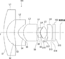
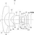
- FIG. 1 is a diagram illustrating a configuration of an imaging apparatus according to a first embodiment.
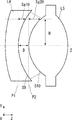
- FIG. 6 is a schematic diagram for explaining conditions of sag amounts of a fourth lens and a fifth lens of the imaging lens system according to the first embodiment.
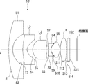
- 1 is a diagram illustrating a configuration of an imaging lens system according to Example 1.
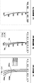
- FIG. FIG. 4 is an aberration diagram of the imaging lens system of Example 1.
- 6 is a diagram illustrating a configuration of an imaging lens system of Example 2.
- FIG. 6 is an aberration diagram of the imaging lens system of Example 2.
- FIG. 6 is a diagram illustrating a configuration of an imaging lens system according to Example 3.
- FIG. 6 is an aberration diagram of the imaging lens system of Example 3.
- FIG. 6 is a diagram illustrating a configuration of an imaging lens system of Example 4.
- FIG. 6 is an aberration diagram of the imaging lens system of Example 4.
- 6 is a diagram illustrating a configuration of an imaging lens system of Example 5.
- FIG. 10 is an aberration diagram of
- FIG. 1 is a diagram illustrating a configuration of an imaging apparatus 100 according to the present embodiment.
- the imaging apparatus 100 includes an imaging lens system 101, a cover glass 102, and an imaging element 103.
- the image sensor 103 is an element that converts received light into an electrical signal.
- a CCD image sensor or a CMOS image sensor is used.
- the image sensor 103 is disposed at the imaging position of the imaging lens system 101.
- the cover glass 102 is provided on the image sensor 103 in order to protect the image sensor 103 from foreign matter.
- the imaging lens system 101 includes, in order from the object side to the image side, a first lens L1 having negative power, a second lens L2 having negative power, a third lens L3 having positive power, and a diaphragm. And a fourth lens L4 having negative power, a fifth lens L5 having positive power, and a sixth lens L6 having positive power.
- the lens surfaces of the imaging lens system 101 are represented as S1 to S13, and the surfaces of the cover glass 102 are represented as S14 and S15.
- the first lens L1 is a meniscus lens having a concave surface facing the image side.
- the second lens L2 has at least one aspherical surface and has a concave surface facing the image side.
- the third lens L3 has a convex surface facing the object side.
- the image side lens surface S9 has an aspherical shape, and a concave surface is directed to the image side.
- the object side lens surface S10 has an aspherical shape, and has a convex surface facing the object side.
- the image side lens surface S9 of the fourth lens L4 and the object side lens surface S10 of the fifth lens L5 are arranged so as not to contact each other and are joined by an adhesive layer.
- the sixth lens L6 has at least one lens surface having an aspheric shape. For example, a resin adhesive is used as the adhesive layer.
- At least one surface is aspherical, and the sixth lens L6 having a positive power is arranged on the most image side of the lens system, so that telecentricity can be improved.
- the imaging lens system 101 includes: The length of the foot of the perpendicular line dropped from the lens surface to the optical axis z is the height from the optical axis, and the sag amount at the height H corresponding to the effective diameter of the object side lens surface S10 of the fifth lens L5 is Sg2H, The sag amount at the same height H as the effective diameter of the object side lens surface S10 of the fifth lens L5 in the image side lens surface S9 of the fourth lens L4 is Sg1H, And when The following conditional expression (1) is satisfied. Sg1H ⁇ Sg2H (1)
- the lens sag amount and the above-described parameters Sg1H and Sg2H will be described with reference to FIG.
- the length of the leg of the perpendicular line dropped from an arbitrary position on the lens surface to the optical axis z is defined as a height h from the optical axis z.
- a perpendicular drawn from the lens surface to the optical axis z is directed in a direction (y-axis direction) orthogonal to the optical axis z.
- the sag amount of the lens surface at the height h from the optical axis z is the light when the plane perpendicular to the optical axis z including the intersection of the lens surface and the optical axis z (z-axis direction) is used as a reference plane. This is the distance in the z-axis direction from the reference surface to the lens surface at the position of the height h from the axis z.
- the reference surface of the image side lens surface S9 of the fourth lens L4 is P1
- the reference surface of the object side lens surface S10 of the fifth lens L5 is P2. If the height from the optical axis z corresponding to the effective diameter of the object side lens surface S10 of the fifth lens L5 is H, Sg2H is the distance from the reference surface P2 to the lens surface S10 at the height H. Sg1H is the distance from the reference surface P1 to the lens surface S9 at the same height H as Sg2H.
- the thickness D of the adhesive layer preferably satisfies the following conditions. 20 ⁇ m ⁇ D ⁇ 100 ⁇ m (16)
- the thickness D of the adhesive layer is set to 20 ⁇ m, and refraction due to the adhesive layer between the joint surfaces is also taken into consideration. If an adhesive is used in the manufacturing stage without considering the presence of the adhesive layer in the design stage in advance, there is a tendency for the shift of the field curvature on the tangential surface to the plus side to increase due to the influence of the adhesive layer between the joint surfaces. is there. By considering the shift of the tangential surface to the plus side of the curvature of field in advance at the time of design, it is possible to perform a design that suppresses the shift of the curvature of field to the plus side.
- the thickness D of the adhesive layer is 100 ⁇ m or less, the shift of the curvature of field on the tangential surface to the plus side due to the increase in the distance between the fourth lens L4 and the fifth lens L5, It is possible to keep within the correction range.
- the imaging lens system 101 that is easy to manufacture and has sufficient aberration correction capability can be provided by the configuration of the present embodiment.
- the cemented surface of the cemented lens is usually a spherical surface, and in this case, the curvature radii of the two surfaces to be cemented are often equal. Accordingly, when spherical cemented lenses are used, an aspherical surface can be used only for two surfaces that are not cemented, and the degree of freedom in lens design is reduced from four surfaces to three surfaces. In the imaging lens system 101 of the present embodiment, since a cemented lens obtained by cementing two lenses having different cemented surfaces is used, there is a degree of freedom for four surfaces in the lens design, and the resolving power can be increased. Furthermore, since aspheric surfaces can be used for all four surfaces, the resolving power can be further increased. However, an imaging lens system including a cemented lens in which spherical surfaces are bonded to each other is not excluded from the present invention.
- the first lens L1 is a glass lens
- the second lens L2 is a glass lens
- the third lens L3, the fourth lens L4, the fifth lens L5, and the sixth lens L6 are It is a plastic lens.
- the first lens L1 and the third lens L3 are glass lenses
- the second lens L2, the fourth lens L4, the fifth lens L5, and the sixth lens L6 are plastic lenses. is there.
- FIG. 3 is a diagram illustrating a configuration of the imaging lens system 101 according to the first embodiment.
- the imaging lens system 101 according to the first exemplary embodiment includes, in order from the object side to the image side, a first lens L1 having a negative power, a second lens L2 having a negative power, and a third lens having a positive power. L3, a stop, a fourth lens L4 having negative power, a fifth lens L5 having positive power, and a sixth lens L6 having positive power.
- the first lens L1 is a spherical meniscus lens having negative power.
- the object side lens surface S1 and the image side lens surface S2 of the first lens L1 are spherical surfaces each having a positive curvature.
- the object side lens surface S1 has a convex surface facing the object side, and the image side lens surface S2 has a concave surface facing the image side.
- the second lens L2 is an aspheric lens having negative power.
- the object side lens surface S3 and the image side lens surface S4 are aspherical surfaces having a positive curvature.
- the object side lens surface S3 has a convex surface facing the object side, and the image side lens surface S4 has a concave surface facing the image side.
- the third lens L3 is an aspheric lens having a positive power.
- the object side lens surface S5 is an aspherical surface having a positive curvature
- the image side lens surface S6 is an aspherical surface having a negative curvature.
- the object side lens surface S5 includes a convex curved surface portion protruding toward the object side
- the image side lens surface S6 includes a convex curved surface portion protruding toward the image side.
- the fourth lens L4 is an aspheric lens having negative power.
- the object side lens surface S8 and the image side lens surface S9 are aspherical surfaces each having a positive curvature.
- the object side lens surface S8 includes a convex curved surface portion protruding toward the object side
- the image side lens surface S9 includes a convex curved surface portion protruding toward the object side.
- the fifth lens L5 is an aspheric lens having a positive power.
- the object side lens surface S10 is an aspherical surface having a positive curvature
- the image side lens surface S11 is an aspherical surface having a negative curvature.
- the object side lens surface S10 includes a convex curved surface portion protruding toward the object side
- the image side lens surface S11 includes a convex curved surface portion protruding toward the image side.
- the sixth lens L6 is an aspheric lens having positive power.
- the object side lens surface S12 is an aspherical surface having a positive curvature
- the image side lens surface S13 is an aspherical surface having a negative curvature.
- the object side lens surface S12 includes a convex curved surface portion protruding toward the object side
- the image side lens surface S13 includes a convex curved surface portion protruding toward the image side.
- Table 1 shows lens data of each lens surface of the imaging lens system 101.
- the lens data includes the radius of curvature, surface spacing, refractive index, and Abbe number of each surface.
- a surface marked with “*” indicates an aspherical surface.
- the aspherical shape adopted for the lens surface is 4th, 6th, 8th, 10th, where Y is the sag amount, c is the reciprocal of the radius of curvature, K is the conic coefficient, and h is the height of the light beam from the optical axis.
- the twelfth, fourteenth, and sixteenth aspherical coefficients are represented by the following equations when A4, A6, A8, A10, A12, A14, and A16 are used.
- Table 2 shows the aspheric coefficients for defining the aspherical shape of the aspherical lens surface in the imaging lens system 101 of Example 1.
- “ ⁇ 2.1058E-03” means “ ⁇ 2.1058 ⁇ 10 ⁇ 3 ”.
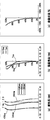
- FIG. 4A to 4C are a longitudinal aberration diagram, a field curvature diagram, and a distortion diagram of the imaging lens system 101 of Example 1.
- FIG. 4A In the longitudinal aberration diagram of FIG. 4A, the horizontal axis indicates the position where the light beam intersects the optical axis z, and the vertical axis indicates the height at the pupil diameter.
- FIG. 4A shows a simulation result using a plurality of light beams having different wavelengths (436 nm, 546 nm, and 656 nm).
- the horizontal axis indicates the distance in the optical axis z direction, and the vertical axis indicates the image height (field angle).
- FIG. 4B In the field curvature diagram of FIG. 4B, the horizontal axis indicates the distance in the optical axis z direction, and the vertical axis indicates the image height (field angle).
- FIG. 4B shows simulation results using light rays having a wavelength of 546 nm.
- FIG. 5 is a diagram illustrating a configuration of the imaging lens system 101 according to the second embodiment.
- the first lens L1, the second lens L2, the third lens L3, the fourth lens L4, and the fifth lens L5 have the same shape as the imaging lens system 101 of the first embodiment. I am doing.
- the sixth lens L6 is an aspheric lens having positive power.
- the object side lens surface S12 is an aspherical surface having a positive curvature
- the image side lens surface S13 is also an aspherical surface having a positive curvature.
- the object side lens surface S12 and the image side lens surface S13 include a convex curved surface portion protruding toward the object side.
- Table 3 shows lens data of each lens surface of the imaging lens system 101.
- a surface marked with “*” indicates an aspherical surface.
- Table 4 shows the aspherical coefficients for defining the aspherical shape of the aspherical lens surface in the imaging lens system 101 of the present example.
- 6A to 6C are a longitudinal aberration diagram, a field curvature diagram, and a distortion diagram of the imaging lens system 101 of the second embodiment.
- FIG. 7 is a diagram illustrating a configuration of the imaging lens system 101 according to the third embodiment.
- the first lens L1, the second lens L2, the fourth lens L4, and the fifth lens L5 have the same shape as the imaging lens system 101 according to the first embodiment.
- the third lens L3 is an aspheric lens having a positive power.
- the object side lens surface S5 and the image side lens surface S6 are aspherical surfaces having a positive curvature.
- the object side lens surface S5 and the image side lens surface S6 include a convex curved surface portion protruding toward the object side.
- the sixth lens L6 is an aspheric lens having positive power.
- the object side lens surface S12 and the image side lens surface S13 are aspherical surfaces having a positive curvature.
- the object side lens surface S12 and the image side lens surface S13 include a convex curved surface portion protruding toward the object side.
- Table 5 shows lens data of each lens surface of the imaging lens system 101.
- a surface marked with “*” indicates an aspherical surface.
- Table 6 shows the aspherical coefficients for defining the aspherical shape of the aspherical lens surface in the imaging lens system 101 of the present embodiment.
- FIG. 8A to 8C are a longitudinal aberration diagram, a field curvature diagram, and a distortion diagram of the imaging lens system 101 of Example 3.
- FIG. 8A to 8C are a longitudinal aberration diagram, a field curvature diagram, and a distortion diagram of the imaging lens system 101 of Example 3.
- FIG. 9 is a diagram illustrating a configuration of the imaging lens system 101 according to the fourth embodiment.
- the first lens L1, the second lens L2, the fourth lens L4, the fifth lens L5, and the sixth lens L6 have the same shape as the imaging lens system 101 of Example 1. I am doing.
- the third lens L3 is an aspheric lens having a positive power.
- the object side lens surface S5 and the image side lens surface S6 are aspherical surfaces having a positive curvature.
- the object side lens surface S5 and the image side lens surface S6 include a convex curved surface portion protruding toward the object side.
- Table 7 shows lens data of each lens surface of the imaging lens system 101.
- a surface marked with “*” indicates an aspherical surface.
- Table 8 shows the aspheric coefficients for defining the aspherical shape of the aspherical lens surface in the imaging lens system 101 of the present embodiment.
- 10A to 10C are a longitudinal aberration diagram, a field curvature diagram, and a distortion diagram of the imaging lens system 101 of Example 4.
- FIG. 10A to 10C are a longitudinal aberration diagram, a field curvature diagram, and a distortion diagram of the imaging lens system 101 of Example 4.
- FIG. 11 is a diagram illustrating a configuration of the imaging lens system 101 according to the fifth embodiment.
- the imaging lens system 101 of Example 5 has the same shape as the imaging lens system 101 of Example 1.
- Table 9 shows lens data of each lens surface of the imaging lens system 101.
- a surface marked with “*” indicates an aspherical surface.
- Table 10 shows the aspheric coefficients for defining the aspherical shape of the aspherical lens surface in the imaging lens system 101 of the present embodiment.
- FIG. 12A to 12C are a longitudinal aberration diagram, a field curvature diagram, and a distortion diagram of the imaging lens system 101 of Example 5.
- FIG. 12A to 12C are a longitudinal aberration diagram, a field curvature diagram, and a distortion diagram of the imaging lens system 101 of Example 5.
- Table 11 shows the results of calculating the characteristic values of the imaging lens systems 101 of Examples 1 to 5.
- the F number is FNo.
- the total field angle (maximum field angle) is 2 ⁇
- the distance from the object side lens surface S1 of the first lens L1 to the imaging surface of the imaging lens system 101 is TL
- the object side lens surface S1 of the first lens L1 is The distance to the image side lens surface S13 of the lens L6
- the focal length of the entire lens system is f
- the focal length of the first lens L1 is f 1
- the focal length of the second lens L2 is f 2
- the third lens L3 The focal length is f 3
- the focal length of the fourth lens L4 is f 4
- the focal length of the fifth lens L5 is f 5
- the focal length of the sixth lens L6 is f 6
- the first lens L1 and the second lens L2 The combined focal length f 12 , the combined focal length of the third lens L 3, the fourth lens L 4,
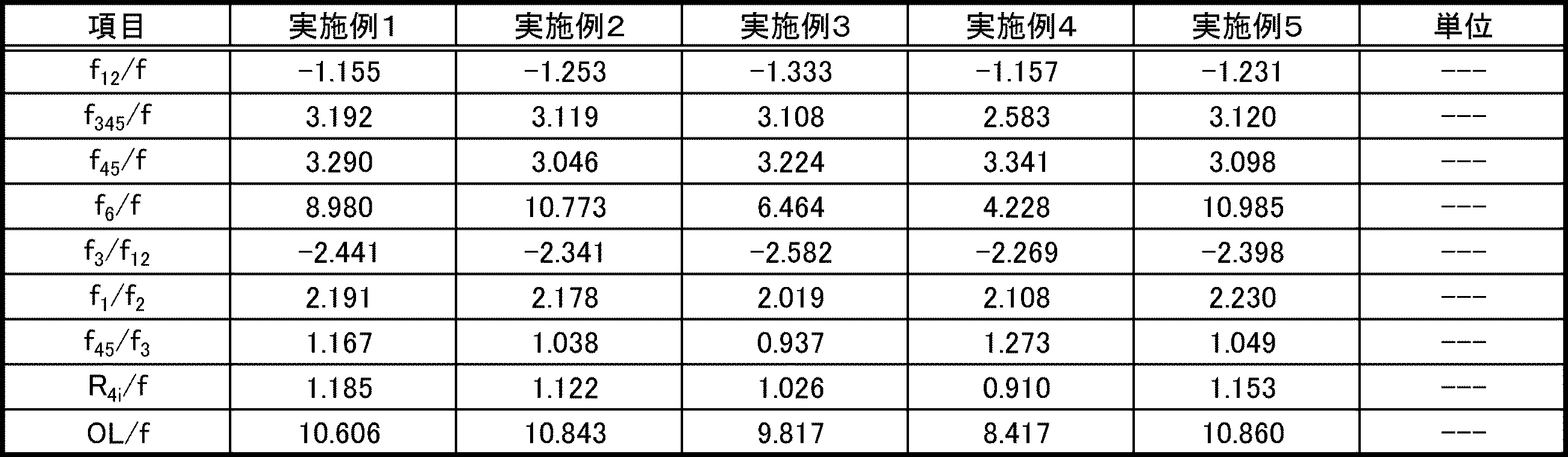
- Table 12 shows the calculation results of the characteristic values that are the parameters of the conditional expressions (1) to (16) in the imaging lens systems 101 of Examples 1 to 5.
- the present invention is not limited to the above-described embodiment, and can be appropriately changed without departing from the spirit of the present invention.
- the application of the imaging lens system 101 of the present invention is not limited to an in-vehicle camera or a surveillance camera, and can be used for other applications such as mounting in a small electronic device such as a mobile phone.
- Imaging device 101 Imaging lens 102 Cover glass 103 Image pick-up element L1-L6 1st lens-6th lens S1-S13 Lens surface S14, S15 Surface of cover glass
Landscapes
- Physics & Mathematics (AREA)
- General Physics & Mathematics (AREA)
- Optics & Photonics (AREA)
- Lenses (AREA)
Abstract
本発明の撮像レンズ系(101)は、物体側から像側に向かって順に、負のパワーを有し、像側に凹面を向けたメニスカス形状の第1レンズ(L1)と、負のパワーを有し、像側に凹面を向けた第2レンズ(L2)と、正のパワーを有し、物体側に凸面を向けた第3レンズ(L3)と、負のパワーを有する第4レンズ(L4)と、正のパワーを有する第5レンズ(L5)と、正のパワーを有する第6レンズ(L6)と、から構成される。撮像レンズ系(101)は、第4レンズ(L4)と第5レンズ(L5)とが、第4レンズ(L4)の像側レンズ面(S9)と第5レンズ(L5)の物体側レンズ面(S10)との間にある接着層により接合されており、レンズ系全体の焦点距離をf、第4レンズ(L4)の像側レンズ面(S9)の曲率半径をR4iとしたときに、条件式「0.9≦R4i/f≦1.3」を満たす。
Description
本発明は、撮像レンズ系および撮像装置に関する。
監視用途の光学系として、屋内外の安全性を確保する監視カメラ用レンズ系、車外および車内監視用の車載カメラ用レンズ系などがある。監視用途の光学系には、視界が極めて広く、かつ、高い解像力を有することが求められる。また、特に、車載カメラ用の撮像レンズ系では、コンパクトさも求められる。
特許文献1には、広角かつ高解像力を有する広角レンズ系が記載されている。この広角レンズ系は、物体側から順に、負の第1レンズ、負の第2レンズ、正の第3レンズ、負の第4レンズ、正の第5レンズ、正の第6レンズの6枚レンズからなる。この広角レンズ系は、第4レンズの像側レンズ面と第5レンズの物体側レンズ面とが接合されている。接合レンズを用いることにより、レンズ系の組み立て時の部品点数の削減ができ、低コスト化に寄与する。
複数のレンズを組み合わせたレンズ系の製造において手間がかかる作業として、接合レンズの貼り合わせがある。接合レンズの接合面においては、凹面と凸面とが接着剤等により貼り合わせられる。
接合レンズの接合面の曲率がきつい場合には、凸面を凹面に嵌め込むのに手間取る上、レンズの嵌め合わせの際に接合面に傷がつきやすいという問題がある。
一方、簡単に嵌めこめるように接合面の曲率を緩くすると、レンズ面に傷がつきにくくなる。しかし、接合面の曲率を緩くすると、十分な収差補正を行うことが難しくなる。
一方、簡単に嵌めこめるように接合面の曲率を緩くすると、レンズ面に傷がつきにくくなる。しかし、接合面の曲率を緩くすると、十分な収差補正を行うことが難しくなる。
本発明は、これらの問題を解決するためなされたものであり、製造しやすく、かつ、十分な収差補正能力を有する撮像レンズ系を提供することを目的とする。
本発明の撮像レンズ系は、
物体側から像側に向かって順に、
負のパワーを有し、像側に凹面を向けたメニスカス形状の第1レンズと、
負のパワーを有し、像側に凹面を向けた第2レンズと、
正のパワーを有し、物体側に凸面を向けた第3レンズと、
負のパワーを有する第4レンズと、
正のパワーを有する第5レンズと、
正のパワーを有する第6レンズと、から構成される撮像レンズ系であって、
前記第4レンズと前記第5レンズとが、前記第4レンズの像側レンズ面と前記第5レンズの物体側レンズ面との間にある接着層により接合されており、
レンズ系全体の焦点距離をf、
前記第4レンズの像側レンズ面の曲率半径をR4i
としたときに、以下の条件式(1)を満たすことを特徴とする。
0.9≦R4i/f≦1.3 (1)
物体側から像側に向かって順に、
負のパワーを有し、像側に凹面を向けたメニスカス形状の第1レンズと、
負のパワーを有し、像側に凹面を向けた第2レンズと、
正のパワーを有し、物体側に凸面を向けた第3レンズと、
負のパワーを有する第4レンズと、
正のパワーを有する第5レンズと、
正のパワーを有する第6レンズと、から構成される撮像レンズ系であって、
前記第4レンズと前記第5レンズとが、前記第4レンズの像側レンズ面と前記第5レンズの物体側レンズ面との間にある接着層により接合されており、
レンズ系全体の焦点距離をf、
前記第4レンズの像側レンズ面の曲率半径をR4i
としたときに、以下の条件式(1)を満たすことを特徴とする。
0.9≦R4i/f≦1.3 (1)
条件式(1)の下限を下回ると、第4レンズの像側レンズ面の曲率半径が小さくなるので、第5レンズの物体側レンズ面との接合が容易ではなくなり、接合レンズを製造する作業性が低下し、コスト高となる。一方、条件式(1)の上限を上回ると、色収差の補正が困難となり、撮像レンズ系の解像力が低下する。
上述の撮像レンズ系は、
前記第4レンズの像側レンズ面および前記第5レンズの物体側レンズ面が非球面形状であり、
前記第4レンズの像側レンズ面と前記第5レンズの物体側レンズ面とが接することがなく、
レンズ面から光軸まで下ろした垂線の足の長さを光軸からの高さとして、前記第5レンズの物体側レンズ面の有効径に相当する高さでのサグ量をSg2H、
前記第4レンズの像側レンズ面における、前記第5レンズの物体側レンズ面の有効径と同じ高さでのサグ量をSg1H、
としたときに、
以下の条件式(2)を満たすことを特徴とする。
Sg1H≦Sg2H (2)
前記第4レンズの像側レンズ面および前記第5レンズの物体側レンズ面が非球面形状であり、
前記第4レンズの像側レンズ面と前記第5レンズの物体側レンズ面とが接することがなく、
レンズ面から光軸まで下ろした垂線の足の長さを光軸からの高さとして、前記第5レンズの物体側レンズ面の有効径に相当する高さでのサグ量をSg2H、
前記第4レンズの像側レンズ面における、前記第5レンズの物体側レンズ面の有効径と同じ高さでのサグ量をSg1H、
としたときに、
以下の条件式(2)を満たすことを特徴とする。
Sg1H≦Sg2H (2)
本発明の撮像レンズ系において、接合レンズを構成する2枚のレンズの接合面である、第4レンズの像側レンズ面と第5レンズの物体側レンズ面とが互いに異なる非球面形状となっている。この構成により、接合レンズを用いて球面収差や色収差などの諸収差を補正することが容易となるので、撮像レンズ系の解像力を高めることができる。
また、条件式(2)を満たすので、互いに異なる非球面形状である第4レンズの像側レンズ面と第5レンズの物体側レンズ面との間の接着層の厚さを大きくすることができる。すなわち、接合レンズを構成する2枚のレンズの接合面の間隔を広くすることができる。これにより、2枚のレンズを接着する接着作業中に接合面を互いに接触させるなどの事故を防止或いは抑制できる。したがって、接合レンズの製造が容易となる。
また、第4レンズと第5レンズとの接合面の間隔が広いので、接合面の間に樹脂接着剤が回り込み易くなる。これにより、2枚のレンズの間に気泡が残留することを防止できる。したがって、接合レンズの製造が容易となる。
上述の撮像レンズ系は、
レンズ系全体の焦点距離をf、
前記第4レンズと前記第5レンズとの合成焦点距離をf45、
としたとき、以下の条件式(3)を満たすことを特徴とする。
2.8≦f45/f≦3.7 (3)
ただし、f45は、前記第4レンズと、前記第5レンズと、前記接着層と、による合成焦点距離である。
レンズ系全体の焦点距離をf、
前記第4レンズと前記第5レンズとの合成焦点距離をf45、
としたとき、以下の条件式(3)を満たすことを特徴とする。
2.8≦f45/f≦3.7 (3)
ただし、f45は、前記第4レンズと、前記第5レンズと、前記接着層と、による合成焦点距離である。
条件式(3)について、さらに好ましくは、
3.0≦f45/f≦3.4
とするのがよい。
3.0≦f45/f≦3.4
とするのがよい。
条件式(3)の上限を上回ると接合レンズのパワーが相対的に弱くなり、色収差の補正不足となる。一方、条件式(3)の下限を下回ると、接合レンズのパワーが相対的に強くなり、接合レンズの各面の曲率半径が小さくなるため、加工・接合の作業が困難になる。それとともに、バックフォーカスの維持が困難となる。
上述の撮像レンズ系は、
レンズ系全体の焦点距離をf、
前記第1レンズの物体側レンズ面から前記第6レンズの像側レンズ面までの距離をOL
としたとき、以下の条件式(4)を満たすことを特徴とする。
7.0≦OL/f≦12 (4)
レンズ系全体の焦点距離をf、
前記第1レンズの物体側レンズ面から前記第6レンズの像側レンズ面までの距離をOL
としたとき、以下の条件式(4)を満たすことを特徴とする。
7.0≦OL/f≦12 (4)
条件式(4)について、さらに好ましくは、
8.0≦OL/f≦11
とするのがよい。
8.0≦OL/f≦11
とするのがよい。
条件式(4)の上限を上回ると、レンズ系の光学全長をコンパクトにすることが困難になる。一方、条件式(4)の下限を下回ると、レンズの最前面から最後面までの距離に対してレンズ系全体の焦点距離が小さくなる。この場合、各レンズのパワーが強くなるため曲率が大きくなり、加工・成形・接合等の製造面で不利になる。
上述の撮像レンズ系は、
前記第3レンズの焦点距離をf3、
前記第4レンズと前記第5レンズとの合成焦点距離をf45
としたとき、以下の条件式(5)を満たすことを特徴とする。
0.8≦f45/f3≦1.4 (5)
ただし、f45は、前記第4レンズと、前記第5レンズと、前記接着層と、による合成焦点距離である。
前記第3レンズの焦点距離をf3、
前記第4レンズと前記第5レンズとの合成焦点距離をf45
としたとき、以下の条件式(5)を満たすことを特徴とする。
0.8≦f45/f3≦1.4 (5)
ただし、f45は、前記第4レンズと、前記第5レンズと、前記接着層と、による合成焦点距離である。
条件式(5)について、さらに好ましくは、
0.85≦f45/f3≦1.35
とするのがよい。
0.85≦f45/f3≦1.35
とするのがよい。
条件式(5)を満足することにより、撮像レンズ系において、良好に球面収差、コマ収差、軸上色収差、及び倍率色収差を補正することができる。条件式(5)の下限を下回ると、第4レンズと第5レンズとの合成焦点距離に対して、第3レンズの正のパワーが相対的に弱くなる。すると、色収差の補正不足となるので、解像力が低下する。一方、条件式(5)の上限を上回ると、第3レンズの正のパワーが相対的に強くなる。このため、色収差の補正が過剰になるとともに、球面収差及びコマ収差の悪化を招くため、解像力が低下する。
上述の撮像レンズ系は、
前記第1レンズと前記第2レンズとの合成焦点距離をf12
としたとき、以下の条件式(6)を満たすことを特徴とする。
-1.4≦f12/f≦-1.0 (6)
前記第1レンズと前記第2レンズとの合成焦点距離をf12
としたとき、以下の条件式(6)を満たすことを特徴とする。
-1.4≦f12/f≦-1.0 (6)
条件式(6)について、さらに好ましくは、
-1.35≦f12/f≦-1.1
とするのがよい。
-1.35≦f12/f≦-1.1
とするのがよい。
条件式(6)の下限を下回ると、第1レンズ及び第2レンズの負のパワーが弱くなる。このため、画角の大きい光線を大きく曲げにくくなるので、超広角を達成することが困難になる。また、バックフォーカスが不足し、像面湾曲が補正不足になる。逆に、条件式(6)の上限を上回ると、第1レンズ及び第2レンズの負のパワーが強くなる。このため、第1レンズの像側レンズ面、第2レンズの像側レンズ面の曲率が強くなり、製造が困難になる。また、像面湾曲の補正が過剰となり、球面収差が正方向に補正過剰になるため、解像力が低下する。
上述の撮像レンズ系は、
レンズ系全体の焦点距離をf、
前記第1レンズと前記第2レンズとの合成焦点距離をf12
前記第3レンズの焦点距離をf3
としたときに、以下の条件式(7)を満たすことを特徴とする。
-2.8≦f3/f12≦-2.0 (7)
レンズ系全体の焦点距離をf、
前記第1レンズと前記第2レンズとの合成焦点距離をf12
前記第3レンズの焦点距離をf3
としたときに、以下の条件式(7)を満たすことを特徴とする。
-2.8≦f3/f12≦-2.0 (7)
条件式(7)について、さらに好ましくは、
-2.6≦f3/f12≦-2.2
とするのがよい。
-2.6≦f3/f12≦-2.2
とするのがよい。
条件式(7)を満足することにより、撮像レンズ系において、軸上色収差及び倍率色収差を補正し、良好な解像特性を得ることができる。条件式(7)の下限を下回ると、第1レンズと第2レンズとの合成パワーに対して、第3レンズの正のパワーが相対的に弱くなり、色収差の補正不足となる。逆に、条件式(7)の上限を上回ると、第3レンズL3の正のパワーが相対的に強くなり、色収差が過剰に補正されるとともに、バックフォーカスの確保するのが難しくなる。
上述の撮像レンズ系は、
前記第1レンズの焦点距離をf1、
前記第2レンズの焦点距離f2
としたとき、以下の条件式(8)を満たすことを特徴とする。
1.9≦f1/f2≦2.4 (8)
前記第1レンズの焦点距離をf1、
前記第2レンズの焦点距離f2
としたとき、以下の条件式(8)を満たすことを特徴とする。
1.9≦f1/f2≦2.4 (8)
条件式(8)について、さらに好ましくは、
2.0≦f1/f2≦2.3
とするのがよい。
2.0≦f1/f2≦2.3
とするのがよい。
条件式(8)は、第1レンズと第2レンズの焦点距離の比を規定したものである。この条件式(8)の上限を上回ると、第1レンズの負のパワーが弱くなる。すると、広角化に不利になるとともに、第1レンズの有効径が大きくなり大型化してしまう。また、バックフォーカスが短くなる要因ともなる。一方、条件式(8)の下限を下回ると第1レンズの負のパワーが相対的に強くなる。すると、像面湾曲の補正が難しくなり、解像力が低下する。
上述の撮像レンズ系は、
前記第1レンズのアッベ数をν1、
前記第2レンズのアッベ数をν2、
前記第3レンズのアッベ数をν3、
前記第4レンズのアッベ数をν4、
前記第5レンズのアッベ数をν5、
前記第6レンズのアッベ数をν6
としたとき、以下の条件式(9)~(14)の全てを満たすことを特徴とする。
ν1≧40 (9)
ν2≧50 (10)
ν3≦35 (11)
ν4≦35 (12)
ν5≧50 (13)
ν6≧50 (14)
前記第1レンズのアッベ数をν1、
前記第2レンズのアッベ数をν2、
前記第3レンズのアッベ数をν3、
前記第4レンズのアッベ数をν4、
前記第5レンズのアッベ数をν5、
前記第6レンズのアッベ数をν6
としたとき、以下の条件式(9)~(14)の全てを満たすことを特徴とする。
ν1≧40 (9)
ν2≧50 (10)
ν3≦35 (11)
ν4≦35 (12)
ν5≧50 (13)
ν6≧50 (14)
条件式(9)~(14)を満たすことにより、軸上色収差、倍率色収差が適正に補正され、高解像力を達成できる。
上述の撮像レンズ系は、
最大画角における主光線入射角度をφH
としたときに、以下の条件式(15)を満たすことを特徴とする。
φh≦16° (15)
最大画角における主光線入射角度をφH
としたときに、以下の条件式(15)を満たすことを特徴とする。
φh≦16° (15)
条件式(15)を満たすことにより、特に広画角側からの入射光束を効率的に撮像素子の各画素に導くことができ、撮像素子で発生するシェーディングを小さく抑えることができる。
さらに、上述の撮像レンズ系は、
前記第2レンズの光軸近傍において、物体側レンズ面が物体側へ凸であることを特徴とするものでもよい。
この構成をとることにより歪曲収差を補正しやすくなる。
前記第2レンズの光軸近傍において、物体側レンズ面が物体側へ凸であることを特徴とするものでもよい。
この構成をとることにより歪曲収差を補正しやすくなる。
また、上述の撮像レンズ系は、
前記第4レンズおよび前記第5レンズはプラスチックレンズである
ことを特徴とするものでもよい。
プラスチックレンズを多用することにより、軽量で安価な撮像レンズ系を提供できる。
前記第4レンズおよび前記第5レンズはプラスチックレンズである
ことを特徴とするものでもよい。
プラスチックレンズを多用することにより、軽量で安価な撮像レンズ系を提供できる。
さらに、上述の撮像レンズ系は、
前記第1レンズがガラスレンズであり、
前記第2レンズ、前記第3レンズ、前記第4レンズ、前記第5レンズ、および前記第6レンズはプラスチックレンズである
ことを特徴とするものでもよい。
第1レンズ以外をすべてプラスチックレンズとすることにより、さらなる軽量化及び製造コストの低減が可能となる。
前記第1レンズがガラスレンズであり、
前記第2レンズ、前記第3レンズ、前記第4レンズ、前記第5レンズ、および前記第6レンズはプラスチックレンズである
ことを特徴とするものでもよい。
第1レンズ以外をすべてプラスチックレンズとすることにより、さらなる軽量化及び製造コストの低減が可能となる。
また、上述の撮像レンズ系は、
前記第1レンズおよび前記第3レンズはガラスレンズであり、
前記第2レンズ、前記第4レンズ、前記第5レンズ、および前記第6レンズはプラスチックレンズである
ことを特徴とするものでもよい。
前記第1レンズおよび前記第3レンズはガラスレンズであり、
前記第2レンズ、前記第4レンズ、前記第5レンズ、および前記第6レンズはプラスチックレンズである
ことを特徴とするものでもよい。
第1レンズ以外をすべてプラスチックレンズとする場合と比べて、第3レンズに高屈折率のガラス材料を用いると、温度変化に対する撮像レンズ系のピントシフトが抑制される。これにより、オートフォーカス機構を持たない撮像装置において、高温時および低温時での結像性能の劣化をより抑制することが期待できる。
本発明の撮像装置は、
上述の撮像レンズ系と、
前記撮像レンズ系の結像位置に配置された撮像素子と、を有する
ことを特徴とするものでもよい。
上述の撮像レンズ系と、
前記撮像レンズ系の結像位置に配置された撮像素子と、を有する
ことを特徴とするものでもよい。
本発明によれば、製造しやすく、かつ、十分な収差補正能力を有する撮像レンズ系を提供できる。
[実施の形態1]
以下、図面を参照して本発明の実施の形態について説明する。
図1は、本実施形態にかかる撮像装置100の構成を示す図である。撮像装置100は、撮像レンズ系101と、カバーガラス102と、撮像素子103と、を備える。
以下、図面を参照して本発明の実施の形態について説明する。
図1は、本実施形態にかかる撮像装置100の構成を示す図である。撮像装置100は、撮像レンズ系101と、カバーガラス102と、撮像素子103と、を備える。
撮像素子103は、受光した光を電気信号に変換する素子であり、例えば、CCDイメージセンサやCMOSイメージセンサが用いられる。撮像素子103は、撮像レンズ系101の結像位置に配置されている。
カバーガラス102は、撮像素子103を異物から保護するために、撮像素子103上に設けられている。
カバーガラス102は、撮像素子103を異物から保護するために、撮像素子103上に設けられている。
撮像レンズ系101は、物体側から像側に向かって順に、負のパワーを有する第1レンズL1と、負のパワーを有する第2レンズL2と、正のパワーを有する第3レンズL3と、絞りと、負のパワーを有する第4レンズL4と、正のパワーを有する第5レンズL5と、正のパワーを有する第6レンズL6と、から構成される。図1に示すように、撮像レンズ系101の各レンズ面はS1~S13、カバーガラス102の各面はS14、S15と表される。
第1レンズL1は、像側に凹面を向けたメニスカス形状のレンズである。第2レンズL2は、少なくとも1面が非球面形状であり、像側に凹面を向けている。第3レンズL3は、物体側に凸面を向けている。
第4レンズL4は、像側レンズ面S9が非球面形状であり、像側に凹面を向けている。第5レンズL5は、物体側レンズ面S10が非球面形状であり、物体側に凸面を向けている。第4レンズL4の像側レンズ面S9と第5レンズL5の物体側レンズ面S10とが、接触しないように配置され、接着層により接合されている。第6レンズL6は、少なくとも一つのレンズ面が非球面形状である。接着層としては、例えば、樹脂接着剤が用いられる。
撮像レンズ系101は、少なくとも1面が非球面形状であり、正のパワーを有する第6レンズL6を、レンズ系の最も像側に配置することにより、テレセントリック性を向上させることができる。
本実施形態にかかる撮像レンズ系101は、
レンズ面から光軸zまで下ろした垂線の足の長さを光軸からの高さとして、第5レンズL5の物体側レンズ面S10の有効径に相当する高さHでのサグ量をSg2H、
第4レンズL4の像側レンズ面S9における、第5レンズL5の物体側レンズ面S10の有効径と同じ高さHでのサグ量をSg1H、
としたときに、
以下の条件式(1)を満たす。
Sg1H≦Sg2H (1)
レンズ面から光軸zまで下ろした垂線の足の長さを光軸からの高さとして、第5レンズL5の物体側レンズ面S10の有効径に相当する高さHでのサグ量をSg2H、
第4レンズL4の像側レンズ面S9における、第5レンズL5の物体側レンズ面S10の有効径と同じ高さHでのサグ量をSg1H、
としたときに、
以下の条件式(1)を満たす。
Sg1H≦Sg2H (1)
図2を用いて、レンズのサグ量と上述のパラメータSg1HおよびSg2Hについて説明する。レンズ面上の任意の位置から光軸zまで下ろした垂線の足の長さを、光軸zからの高さhとする。レンズ面から光軸zに下ろされた垂線は、光軸zと直交する方向(y軸方向)を向く。光軸zからの高さhにおけるレンズ面のサグ量とは、レンズ面と光軸z(z軸方向)との交点を含んだ光軸zと直交する平面を基準面としたときに、光軸zからの高さhの位置における、基準面からレンズ面までのz軸方向の距離である。
図2において、第4レンズL4の像側レンズ面S9の基準面をP1,第5レンズL5の物体側レンズ面S10の基準面をP2とする。第5レンズL5の物体側レンズ面S10の有効径に相当する光軸zからの高さをHとすると、Sg2Hは、高さHにおける基準面P2からレンズ面S10までの距離である。Sg1Hは、Sg2Hと同じ高さHにおける基準面P1からレンズ面S9までの距離である。
接合レンズを構成する第4レンズL4の像側レンズ面S9と第5レンズL5の物体側レンズ面S10との間にある接着層の厚さについて考える。撮像レンズ系101の光軸zに沿った方向の接着層の厚さをDとすると、
接着層の厚さDは以下の条件を満たすことが望ましい。
20μm≦D≦100μm (16)
接着層の厚さDは以下の条件を満たすことが望ましい。
20μm≦D≦100μm (16)
撮像レンズ系101の設計時においては、接着層の厚さDを20μmとして、接合面間の接着層による屈折も考慮されている。設計段階で接着層の存在を予め考慮せずに製造段階で接着剤を使用すると、接合面間の接着層の影響により、タンジェンシャル面における像面湾曲のプラス側へのシフトが大きくなる傾向がある。タンジェンシャル面における像面湾曲のプラス側へのシフトを、設計時に予め考慮しておくことにより、像面湾曲のプラス側へのシフトを抑制した設計が可能となる。
また、接着層の厚さDが100μm以下であれば、第4レンズL4と第5レンズL5との間隔が広くなることに起因するタンジェンシャル面での像面湾曲のプラス側へのシフトを、補正が可能な範囲に収めることができる。
以上、説明したように、本実施形態の構成により、製造しやすく、かつ、十分な収差補正能力を有する撮像レンズ系101を提供するができる。
接合レンズの接合面は通常は球面であり、その場合、接合する2面の曲率半径は等しくなっていることが多い。よって、球面同士の接合レンズを用いると、接合しない2つの面にのみしか非球面を用いることができず、さらに、レンズ設計における自由度が4面から3面に減少する。
本実施形態の撮像レンズ系101では、接合面の形状が異なる2枚のレンズを接合した接合レンズを用いているので、レンズ設計において4面分の自由度があり、解像力を高めることができる。さらに、4面すべてに非球面を用いることもできるので、解像力をより高めることが可能である。ただし、本発明から球面同士を貼り合わせた接合レンズを含む撮像レンズ系を除外するものではない。
本実施形態の撮像レンズ系101では、接合面の形状が異なる2枚のレンズを接合した接合レンズを用いているので、レンズ設計において4面分の自由度があり、解像力を高めることができる。さらに、4面すべてに非球面を用いることもできるので、解像力をより高めることが可能である。ただし、本発明から球面同士を貼り合わせた接合レンズを含む撮像レンズ系を除外するものではない。
以下、本発明の撮像レンズ系101の実施例について説明する。
実施例1、3、および5の撮像レンズ101は、第1レンズL1がガラスレンズであり、第2レンズL2、第3レンズL3、第4レンズL4、第5レンズL5、および第6レンズL6はプラスチックレンズである。
実施例1、3、および5の撮像レンズ101は、第1レンズL1がガラスレンズであり、第2レンズL2、第3レンズL3、第4レンズL4、第5レンズL5、および第6レンズL6はプラスチックレンズである。
実施例2および4の撮像レンズ101は、第1レンズL1および第3レンズL3がガラスレンズであり、第2レンズL2、第4レンズL4、第5レンズL5、および第6レンズL6はプラスチックレンズである。
(実施例1)
図3は、実施例1の撮像レンズ系101の構成を示す図である。
実施例1の撮像レンズ系101は、物体側から像側に向かって順に、負のパワーを有する第1レンズL1と、負のパワーを有する第2レンズL2と、正のパワーを有する第3レンズL3と、絞りと、負のパワーを有する第4レンズL4と、正のパワーを有する第5レンズL5と、正のパワーを有する第6レンズL6と、から構成される。
図3は、実施例1の撮像レンズ系101の構成を示す図である。
実施例1の撮像レンズ系101は、物体側から像側に向かって順に、負のパワーを有する第1レンズL1と、負のパワーを有する第2レンズL2と、正のパワーを有する第3レンズL3と、絞りと、負のパワーを有する第4レンズL4と、正のパワーを有する第5レンズL5と、正のパワーを有する第6レンズL6と、から構成される。
第1レンズL1は、負のパワーを有する球面メニスカスレンズである。第1レンズL1の物体側レンズ面S1および像側レンズ面S2は、それぞれが正の曲率を備えた球面である。物体側レンズ面S1は物体側に凸面を向けており、像側レンズ面S2は像側に凹面を向けている。
第2レンズL2は、負のパワーを有する非球面レンズである。物体側レンズ面S3および像側レンズ面S4は、正の曲率を備えた非球面である。物体側レンズ面S3は物体側に凸面を向けており、像側レンズ面S4は像側に凹面を向けている。
第3レンズL3は、正のパワーを有する非球面レンズである。物体側レンズ面S5は正の曲率を備えた非球面であり、像側レンズ面S6は負の曲率を備えた非球面である。物体側レンズ面S5は物体側に突出する凸形状の曲面部分を備えており、像側レンズ面S6は像側に突出する凸形状の曲面部分を備えている。
第4レンズL4は、負のパワーを有する非球面レンズである。物体側レンズ面S8および像側レンズ面S9は、それぞれが正の曲率を備えた非球面である。物体側レンズ面S8は物体側に突出する凸形状の曲面部分を備えており、像側レンズ面S9は物体側に突出する凸形状の曲面部分を備えている。
第5レンズL5は、正のパワーを有する非球面レンズである。物体側レンズ面S10は正の曲率を備えた非球面であり、像側レンズ面S11は負の曲率を備えた非球面である。物体側レンズ面S10は物体側に突出する凸形状の曲面部分を備えており、像側レンズ面S11は像側に突出する凸形状の曲面部分を備えている。
第6レンズL6は、正のパワーを有する非球面レンズである。物体側レンズ面S12は正の曲率を備えた非球面であり、像側レンズ面S13は負の曲率を備えた非球面である。物体側レンズ面S12は物体側に突出する凸形状の曲面部分を備えており、像側レンズ面S13は像側に突出する凸形状の曲面部分を備えている。
表1に、撮像レンズ系101の各レンズ面のレンズデータを示す。レンズデータとしては、各面の曲率半径、面間隔、屈折率、およびアッベ数を載せている。「*印」がついた面は、非球面であることを示している。

レンズ面に採用する非球面形状は、Yをサグ量、cを曲率半径の逆数、Kを円錐係数、hを光軸からの光線高さとして、4次、6次、8次、10次、12次、14次、16次の非球面係数をそれぞれA4、A6、A8、A10、A12、A14、A16としたときに、次式により表わされる。

表2に、実施例1の撮像レンズ系101において、非球面とされたレンズ面の非球面形状を規定するための非球面係数を示す。表2において、例えば「-2.1058E-03」は、「-2.1058×10⁻³」を意味する。

図4(a)~(c)は、実施例1の撮像レンズ系101の縦収差図、像面湾曲図、歪曲収差図である。図4(a)の縦収差図では、横軸は光線が光軸zと交わる位置を示し、縦軸は瞳径での高さを示す。図4(a)では、波長の異なる複数の光線(436nm、546nm、656nm)によるシミュレーション結果を示してある。図4(b)の像面湾曲図では、横軸は光軸z方向の距離を示し、縦軸は像高(画角)を示す。図4(b)において、Sagはサジタル面における像面湾曲を示し、Tanはタンジェンシャル面における像面湾曲を示す。図4(c)の歪曲収差図では、横軸は像の歪み量(%)を示し、縦軸は像高(画角)を示す。図4(b)および図4(c)では、波長546nmの光線によるシミュレーション結果を示してある。
(実施例2)
図5は、実施例2の撮像レンズ系101の構成を示す図である。
実施例2の撮像レンズ系101においては、第1レンズL1、第2レンズL2、第3レンズL3、第4レンズL4、および第5レンズL5は、実施例1の撮像レンズ系101と同様の形状をしている。
図5は、実施例2の撮像レンズ系101の構成を示す図である。
実施例2の撮像レンズ系101においては、第1レンズL1、第2レンズL2、第3レンズL3、第4レンズL4、および第5レンズL5は、実施例1の撮像レンズ系101と同様の形状をしている。
第6レンズL6は、正のパワーを有する非球面レンズである。物体側レンズ面S12は正の曲率を備えた非球面であり、像側レンズ面S13も正の曲率を備えた非球面である。物体側レンズ面S12および像側レンズ面S13は、物体側に突出する凸形状の曲面部分を備えている。
表3に、撮像レンズ系101の各レンズ面のレンズデータを示す。「*印」がついた面は、非球面であることを示している。
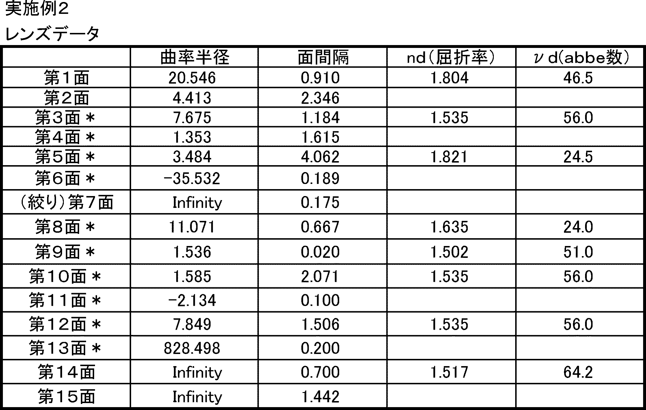
表4に、本実施例の撮像レンズ系101において、非球面とされたレンズ面の非球面形状を規定するための非球面係数を示す。
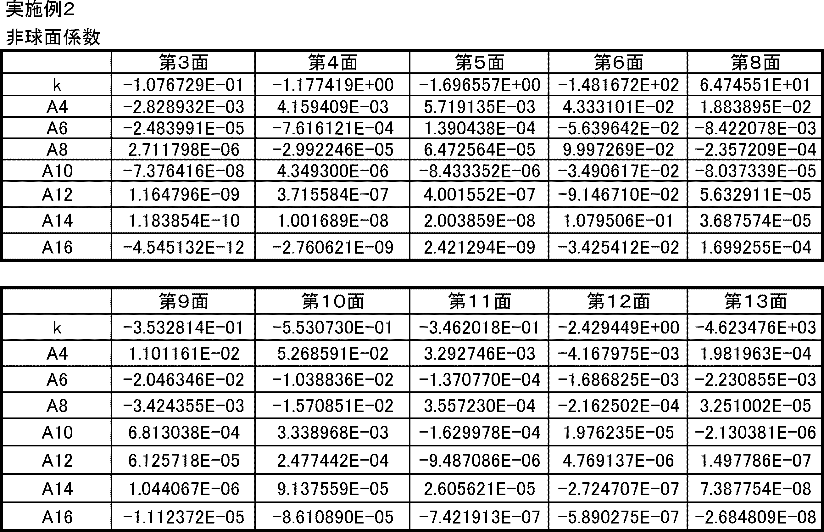
図6(a)~(c)は、実施例2の撮像レンズ系101の縦収差図、像面湾曲図、歪曲収差図である。
(実施例3)
図7は、実施例3の撮像レンズ系101の構成を示す図である。
実施例3の撮像レンズ系101においては、第1レンズL1、第2レンズL2、第4レンズL4、および第5レンズL5は、実施例1の撮像レンズ系101と同様の形状をしている。
図7は、実施例3の撮像レンズ系101の構成を示す図である。
実施例3の撮像レンズ系101においては、第1レンズL1、第2レンズL2、第4レンズL4、および第5レンズL5は、実施例1の撮像レンズ系101と同様の形状をしている。
第3レンズL3は、正のパワーを有する非球面レンズである。物体側レンズ面S5および像側レンズ面S6は正の曲率を備えた非球面である。物体側レンズ面S5および像側レンズ面S6は、物体側に突出する凸形状の曲面部分を備えている。
第6レンズL6は、正のパワーを有する非球面レンズである。物体側レンズ面S12および像側レンズ面S13は正の曲率を備えた非球面である。物体側レンズ面S12および像側レンズ面S13は、物体側に突出する凸形状の曲面部分を備えている。
表5に、撮像レンズ系101の各レンズ面のレンズデータを示す。「*印」がついた面は、非球面であることを示している。
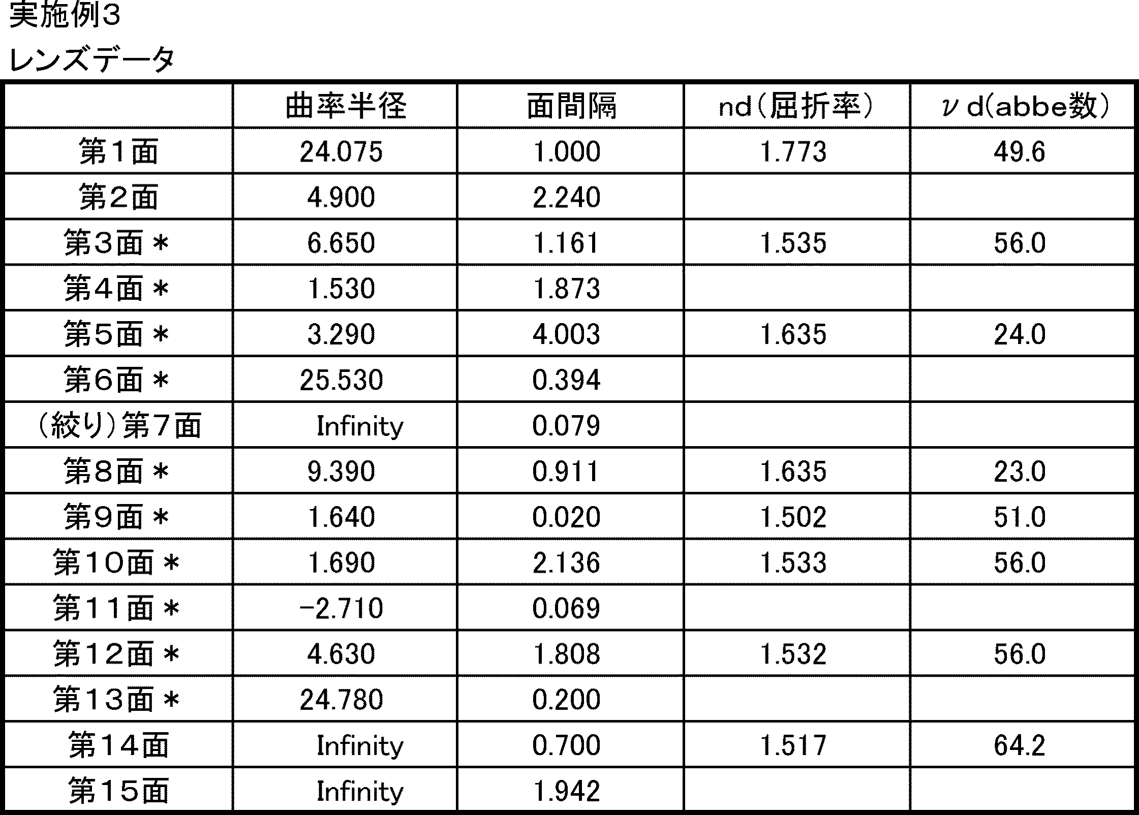
表6に、本実施例の撮像レンズ系101において、非球面とされたレンズ面の非球面形状を規定するための非球面係数を示す。

図8(a)~(c)は、実施例3の撮像レンズ系101の縦収差図、像面湾曲図、歪曲収差図である。
(実施例4)
図9は、実施例4の撮像レンズ系101の構成を示す図である。
実施例4の撮像レンズ系101においては、第1レンズL1、第2レンズL2、第4レンズL4、第5レンズL5、および第6レンズL6は、実施例1の撮像レンズ系101と同様の形状をしている。
図9は、実施例4の撮像レンズ系101の構成を示す図である。
実施例4の撮像レンズ系101においては、第1レンズL1、第2レンズL2、第4レンズL4、第5レンズL5、および第6レンズL6は、実施例1の撮像レンズ系101と同様の形状をしている。
第3レンズL3は、正のパワーを有する非球面レンズである。物体側レンズ面S5および像側レンズ面S6は正の曲率を備えた非球面である。物体側レンズ面S5および像側レンズ面S6は、物体側に突出する凸形状の曲面部分を備えている。
表7に、撮像レンズ系101の各レンズ面のレンズデータを示す。「*印」がついた面は、非球面であることを示している。
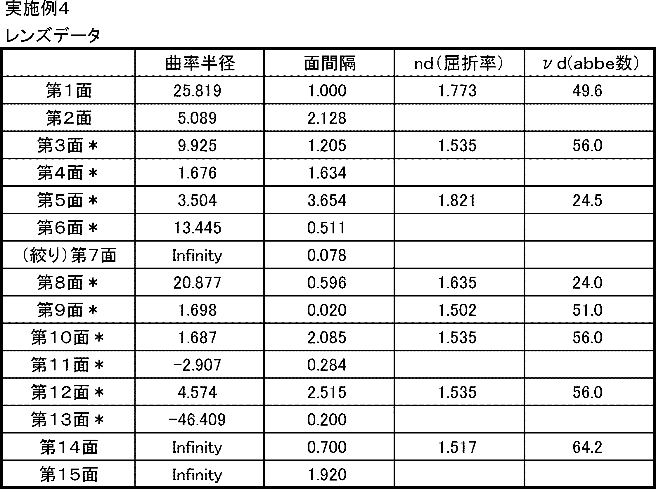
表8に、本実施例の撮像レンズ系101において、非球面とされたレンズ面の非球面形状を規定するための非球面係数を示す。

図10(a)~(c)は、実施例4の撮像レンズ系101の縦収差図、像面湾曲図、歪曲収差図である。
(実施例5)
図11は、実施例5の撮像レンズ系101の構成を示す図である。
実施例5の撮像レンズ系101は、実施例1の撮像レンズ系101と同様の形状をしている。
図11は、実施例5の撮像レンズ系101の構成を示す図である。
実施例5の撮像レンズ系101は、実施例1の撮像レンズ系101と同様の形状をしている。
表9に、撮像レンズ系101の各レンズ面のレンズデータを示す。「*印」がついた面は、非球面であることを示している。

表10に、本実施例の撮像レンズ系101において、非球面とされたレンズ面の非球面形状を規定するための非球面係数を示す。
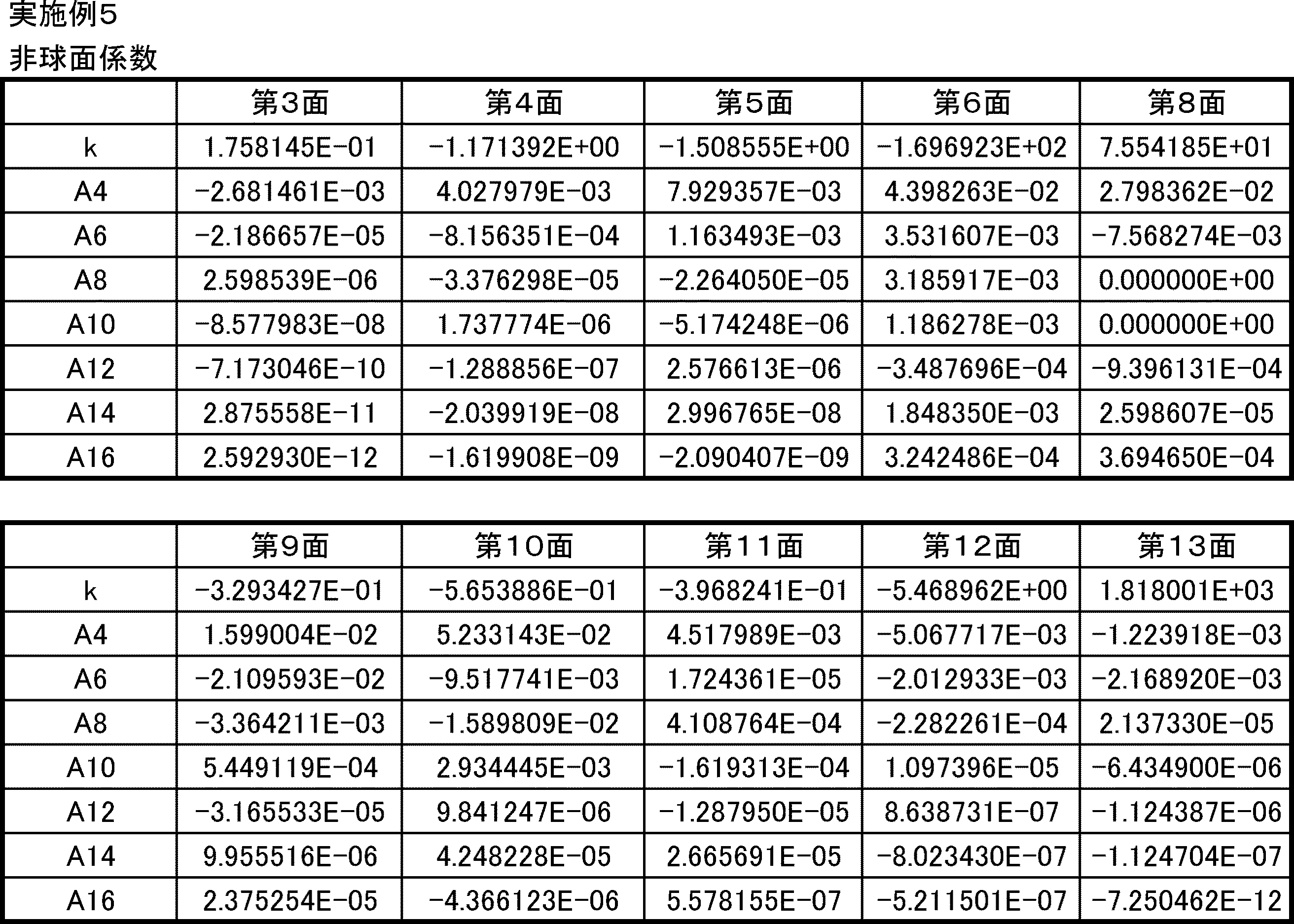
図12(a)~(c)は、実施例5の撮像レンズ系101の縦収差図、像面湾曲図、歪曲収差図である。
表11に、実施例1~5の撮像レンズ系101の特性値を計算した結果を示す。撮像レンズ系101において、FナンバーをFNo.、全画角(最大画角)を2ω、第1レンズL1の物体側レンズ面S1から撮像レンズ系101の結像面までの距離をTL、第1レンズL1の物体側レンズ面S1から第6レンズL6の像側レンズ面S13までの距離をOL、レンズ系全体の焦点距離をf、第1レンズL1の焦点距離をf1、第2レンズL2の焦点距離をf2、第3レンズL3の焦点距離をf3、第4レンズL4の焦点距離をf4、第5レンズL5の焦点距離をf5、第6レンズL6の焦点距離をf6、第1レンズL1と第2レンズL2との合成焦点距離f12、第3レンズL3と第4レンズL4と第5レンズL5との合成焦点距離(接着層を含む)をf345、第4レンズL4と第5レンズL5との合成焦点距離(接着層を含む)をf45、第4レンズL4の像側レンズ面S9の曲率半径R4i、水平画角における主光線入射角度をφh、としたときのこれらの特性値は、表11に示す通りである。全画角2ω、主光線入射角度φh、および各種の焦点距離は、546nmの波長の光線を用いて計算した。

表12に、実施例1~5の撮像レンズ系101において、条件式(1)~(16)のパラメータとなる特性値を計算した結果を示す。
なお、本発明は上記実施の形態に限られたものではなく、趣旨を逸脱しない範囲で適宜変更することが可能である。例えば、本発明の撮像レンズ系101の用途は、車載カメラや監視カメラに限定されるものではなく、携帯電話等の小型電子機器に搭載する等の他の用途にも用いることができる。
この出願は、2013年9月20日に出願された日本出願特願2013-195936を基礎とする優先権を主張し、その開示の全てをここに取り込む。
100 撮像装置
101 撮像レンズ
102 カバーガラス
103 撮像素子
L1~L6 第1レンズ~第6レンズ
S1~S13 レンズ面
S14、S15 カバーガラスの面
101 撮像レンズ
102 カバーガラス
103 撮像素子
L1~L6 第1レンズ~第6レンズ
S1~S13 レンズ面
S14、S15 カバーガラスの面
Claims (15)
- 物体側から像側に向かって順に、
負のパワーを有し、像側に凹面を向けたメニスカス形状の第1レンズと、
負のパワーを有し、像側に凹面を向けた第2レンズと、
正のパワーを有し、物体側に凸面を向けた第3レンズと、
負のパワーを有する第4レンズと、
正のパワーを有する第5レンズと、
正のパワーを有する第6レンズと、から構成される撮像レンズ系であって、
前記第4レンズと前記第5レンズとが、前記第4レンズの像側レンズ面と前記第5レンズの物体側レンズ面との間にある接着層により接合されており、
レンズ系全体の焦点距離をf、
前記第4レンズの像側レンズ面の曲率半径をR4i
としたときに、以下の条件式(1)を満たすことを特徴とする撮像レンズ系。
0.9≦R4i/f≦1.3 (1) - 請求項1に記載の撮像レンズ系であって、
前記第4レンズの像側レンズ面および前記第5レンズの物体側レンズ面が非球面形状であり、
前記第4レンズの像側レンズ面と前記第5レンズの物体側レンズ面とが接することがなく、
レンズ面から光軸まで下ろした垂線の足の長さを光軸からの高さとして、前記第5レンズの物体側レンズ面の有効径に相当する高さでのサグ量をSg2H、
前記第4レンズの像側レンズ面における、前記第5レンズの物体側レンズ面の有効径と同じ高さでのサグ量をSg1H、
としたときに、
以下の条件式(2)を満たすことを特徴とする撮像レンズ系。
Sg1H≦Sg2H (2) - 請求項1又は2に記載の撮像レンズ系であって、
レンズ系全体の焦点距離をf、
前記第4レンズと前記第5レンズとの合成焦点距離をf45、
としたとき、以下の条件式(3)を満たすことを特徴とする撮像レンズ系。
2.8≦f45/f≦3.7 (3)
ただし、f45は、前記第4レンズと、前記第5レンズと、前記接着層と、による合成焦点距離である。 - 請求項1~3のいずれか1項に記載の撮像レンズ系であって、
レンズ系全体の焦点距離をf、
前記第1レンズの物体側レンズ面から前記第6レンズの像側レンズ面までの距離をOL
としたとき、以下の条件式(4)を満たすことを特徴とする撮像レンズ系。
7.0≦OL/f≦12 (4) - 請求項1~4のいずれか1項に記載の撮像レンズ系であって、
前記第3レンズの焦点距離をf3、
前記第4レンズと前記第5レンズとの合成焦点距離をf45
としたとき、以下の条件式(5)を満たすことを特徴とする撮像レンズ系。
0.8≦f45/f3≦1.4 (5)
ただし、f45は、前記第4レンズと、前記第5レンズと、前記接着層と、による合成焦点距離である。 - 請求項1~5のいずれか1項に記載の撮像レンズ系であって、
レンズ系全体の焦点距離をf、
前記第1レンズと前記第2レンズとの合成焦点距離をf12
としたとき、以下の条件式(6)を満たすことを特徴とする撮像レンズ系。
-1.4≦f12/f≦-1.0 (6) - 請求項1~6のいずれか1項に記載の撮像レンズ系であって、
前記第1レンズと前記第2レンズとの合成焦点距離をf12
前記第3レンズの焦点距離をf3
としたときに、以下の条件式(7)を満たすことを特徴とする撮像レンズ系。
-2.8≦f3/f12≦-2.0 (7) - 請求項1~7のいずれか1項に記載の撮像レンズ系であって、
前記第1レンズの焦点距離をf1、
前記第2レンズの焦点距離f2
としたとき、以下の条件式(8)を満たすことを特徴とする撮像レンズ系。
1.9≦f1/f2≦2.4 (8) - 請求項1~8のいずれか1項に記載の撮像レンズ系であって、
前記第1レンズのアッベ数をν1、
前記第2レンズのアッベ数をν2、
前記第3レンズのアッベ数をν3、
前記第4レンズのアッベ数をν4、
前記第5レンズのアッベ数をν5、
前記第6レンズのアッベ数をν6
としたとき、以下の条件式(9)~(14)の全てを満たすことを特徴とする撮像レンズ系。
ν1≧40 (9)
ν2≧50 (10)
ν3≦35 (11)
ν4≦35 (12)
ν5≧50 (13)
ν6≧50 (14) - 請求項1~9のいずれか1項に記載の撮像レンズ系において、
最大画角における主光線入射角度をφH
としたときに、以下の条件式(15)を満たすことを特徴とする撮像レンズ系。
φh≦16° (15) - 請求項1~10のいずれか1項に記載の撮像レンズ系であって、
前記第2レンズの光軸近傍において、物体側レンズ面が物体側へ凸であることを特徴とする撮像レンズ系。 - 請求項1~11のいずれか1項に記載の撮像レンズ系であって、
前記第4レンズおよび前記第5レンズはプラスチックレンズである
ことを特徴とする撮像レンズ系。 - 請求項1~12のいずれか1項に記載の撮像レンズ系であって、
前記第1レンズがガラスレンズであり、
前記第2レンズ、前記第3レンズ、前記第4レンズ、前記第5レンズ、および前記第6レンズはプラスチックレンズである
ことを特徴とする撮像レンズ系。 - 請求項1~12のいずれか1項に記載の撮像レンズ系であって、
前記第1レンズおよび前記第3レンズはガラスレンズであり、
前記第2レンズ、前記第4レンズ、前記第5レンズ、および前記第6レンズはプラスチックレンズである
ことを特徴とする撮像レンズ系。 - 請求項1~14のいずれか1項に記載の撮像レンズ系と、
前記撮像レンズ系の結像位置に配置された撮像素子と、を有する
ことを特徴とする撮像装置。
Applications Claiming Priority (2)
| Application Number | Priority Date | Filing Date | Title |
|---|---|---|---|
| JP2013195936A JP2015060201A (ja) | 2013-09-20 | 2013-09-20 | 撮像レンズ系および撮像装置 |
| JP2013-195936 | 2013-09-20 |
Publications (1)
| Publication Number | Publication Date |
|---|---|
| WO2015040808A1 true WO2015040808A1 (ja) | 2015-03-26 |
Family
ID=52688479
Family Applications (1)
| Application Number | Title | Priority Date | Filing Date |
|---|---|---|---|
| PCT/JP2014/004499 Ceased WO2015040808A1 (ja) | 2013-09-20 | 2014-09-02 | 撮像レンズ系および撮像装置 |
Country Status (2)
| Country | Link |
|---|---|
| JP (1) | JP2015060201A (ja) |
| WO (1) | WO2015040808A1 (ja) |
Cited By (9)
| Publication number | Priority date | Publication date | Assignee | Title |
|---|---|---|---|---|
| CN108646388A (zh) * | 2018-07-26 | 2018-10-12 | 协益电子(苏州)有限公司 | 车载镜头 |
| CN108663785A (zh) * | 2017-04-01 | 2018-10-16 | 宁波舜宇车载光学技术有限公司 | 光学镜头和成像设备 |
| CN108873270A (zh) * | 2018-07-13 | 2018-11-23 | 舜宇光学(中山)有限公司 | 玻塑混合定焦镜头 |
| CN109425957A (zh) * | 2017-08-25 | 2019-03-05 | 宁波舜宇车载光学技术有限公司 | 光学镜头 |
| CN109613686A (zh) * | 2018-12-21 | 2019-04-12 | 江西特莱斯光学有限公司 | 一种无热化超薄广角镜头 |
| CN110174744A (zh) * | 2018-02-19 | 2019-08-27 | 日本电产三协株式会社 | 广角镜头 |
| JP2019168491A (ja) * | 2018-03-22 | 2019-10-03 | コニカミノルタ株式会社 | 広角レンズ、レンズユニット、及び撮像装置 |
| US10901185B2 (en) | 2017-06-28 | 2021-01-26 | Zhejiang Sunny Optical Co., Ltd. | Optical imaging system |
| CN117389008A (zh) * | 2023-12-11 | 2024-01-12 | 江西联创电子有限公司 | 光学镜头 |
Families Citing this family (13)
| Publication number | Priority date | Publication date | Assignee | Title |
|---|---|---|---|---|
| US9104009B2 (en) * | 2013-12-20 | 2015-08-11 | Genius Electronic Optical Co., Ltd. | Optical imaging system and electronic apparatus including the same |
| KR102508341B1 (ko) * | 2015-09-04 | 2023-03-10 | 삼성전자주식회사 | 초광곽 광학계 |
| KR101883151B1 (ko) * | 2015-11-26 | 2018-07-30 | 삼성전기주식회사 | 촬상 광학계 |
| WO2018029748A1 (ja) * | 2016-08-08 | 2018-02-15 | 株式会社トヨテック | 広角レンズ |
| JP6695995B2 (ja) * | 2016-10-05 | 2020-05-20 | マクセル株式会社 | 撮像レンズ系及び撮像装置 |
| CN108663773B (zh) * | 2017-03-31 | 2020-10-23 | 宁波舜宇车载光学技术有限公司 | 光学镜头和成像设备 |
| JP6587293B2 (ja) * | 2017-06-15 | 2019-10-09 | カンタツ株式会社 | 撮像レンズ |
| TWI632411B (zh) | 2018-01-19 | 2018-08-11 | 大立光電股份有限公司 | 光學攝像鏡組、取像裝置及電子裝置 |
| CN108287403B (zh) | 2018-05-02 | 2023-06-16 | 浙江舜宇光学有限公司 | 光学成像镜头 |
| JP2021006858A (ja) * | 2019-06-28 | 2021-01-21 | セイコーエプソン株式会社 | 投射光学系およびプロジェクター |
| JP2021006859A (ja) * | 2019-06-28 | 2021-01-21 | セイコーエプソン株式会社 | 投射光学系およびプロジェクター |
| CN113640973B (zh) * | 2021-10-15 | 2022-02-11 | 江西联创电子有限公司 | 光学成像镜头及成像设备 |
| CN116149019B (zh) * | 2023-02-20 | 2025-11-25 | 福建福光天瞳光学有限公司 | 一种低照度高清光学镜头 |
Citations (7)
| Publication number | Priority date | Publication date | Assignee | Title |
|---|---|---|---|---|
| JPH11249009A (ja) * | 1998-03-06 | 1999-09-17 | Asahi Optical Co Ltd | 撮影レンズ系 |
| JP2004245893A (ja) * | 2003-02-10 | 2004-09-02 | Tamron Co Ltd | レトロフォーカス型広角レンズ |
| JP2006284620A (ja) * | 2005-03-31 | 2006-10-19 | Nidec Nissin Corp | 広角レンズおよび接合レンズ |
| JP2008040033A (ja) * | 2006-08-04 | 2008-02-21 | Sigma Corp | 広角レンズ |
| JP2008275666A (ja) * | 2007-04-25 | 2008-11-13 | Kyocera Corp | 撮像光学装置および監視カメラ |
| JP2009063877A (ja) * | 2007-09-07 | 2009-03-26 | Nidec Nissin Corp | 超広角レンズ |
| JP2013040992A (ja) * | 2011-08-11 | 2013-02-28 | Pentax Ricoh Imaging Co Ltd | 超広角レンズ系 |
-
2013
- 2013-09-20 JP JP2013195936A patent/JP2015060201A/ja active Pending
-
2014
- 2014-09-02 WO PCT/JP2014/004499 patent/WO2015040808A1/ja not_active Ceased
Patent Citations (7)
| Publication number | Priority date | Publication date | Assignee | Title |
|---|---|---|---|---|
| JPH11249009A (ja) * | 1998-03-06 | 1999-09-17 | Asahi Optical Co Ltd | 撮影レンズ系 |
| JP2004245893A (ja) * | 2003-02-10 | 2004-09-02 | Tamron Co Ltd | レトロフォーカス型広角レンズ |
| JP2006284620A (ja) * | 2005-03-31 | 2006-10-19 | Nidec Nissin Corp | 広角レンズおよび接合レンズ |
| JP2008040033A (ja) * | 2006-08-04 | 2008-02-21 | Sigma Corp | 広角レンズ |
| JP2008275666A (ja) * | 2007-04-25 | 2008-11-13 | Kyocera Corp | 撮像光学装置および監視カメラ |
| JP2009063877A (ja) * | 2007-09-07 | 2009-03-26 | Nidec Nissin Corp | 超広角レンズ |
| JP2013040992A (ja) * | 2011-08-11 | 2013-02-28 | Pentax Ricoh Imaging Co Ltd | 超広角レンズ系 |
Cited By (14)
| Publication number | Priority date | Publication date | Assignee | Title |
|---|---|---|---|---|
| CN108663785A (zh) * | 2017-04-01 | 2018-10-16 | 宁波舜宇车载光学技术有限公司 | 光学镜头和成像设备 |
| CN108663785B (zh) * | 2017-04-01 | 2022-03-04 | 宁波舜宇车载光学技术有限公司 | 光学镜头和成像设备 |
| US10901185B2 (en) | 2017-06-28 | 2021-01-26 | Zhejiang Sunny Optical Co., Ltd. | Optical imaging system |
| CN109425957A (zh) * | 2017-08-25 | 2019-03-05 | 宁波舜宇车载光学技术有限公司 | 光学镜头 |
| CN110174744B (zh) * | 2018-02-19 | 2021-11-05 | 日本电产三协株式会社 | 广角镜头 |
| CN110174744A (zh) * | 2018-02-19 | 2019-08-27 | 日本电产三协株式会社 | 广角镜头 |
| US11016275B2 (en) | 2018-02-19 | 2021-05-25 | Nidec Sankyo Corporation | Wide-angle lens |
| JP2019168491A (ja) * | 2018-03-22 | 2019-10-03 | コニカミノルタ株式会社 | 広角レンズ、レンズユニット、及び撮像装置 |
| CN108873270A (zh) * | 2018-07-13 | 2018-11-23 | 舜宇光学(中山)有限公司 | 玻塑混合定焦镜头 |
| CN108873270B (zh) * | 2018-07-13 | 2024-04-12 | 舜宇光学(中山)有限公司 | 玻塑混合定焦镜头 |
| CN108646388A (zh) * | 2018-07-26 | 2018-10-12 | 协益电子(苏州)有限公司 | 车载镜头 |
| CN109613686A (zh) * | 2018-12-21 | 2019-04-12 | 江西特莱斯光学有限公司 | 一种无热化超薄广角镜头 |
| CN117389008A (zh) * | 2023-12-11 | 2024-01-12 | 江西联创电子有限公司 | 光学镜头 |
| CN117389008B (zh) * | 2023-12-11 | 2024-04-26 | 江西联创电子有限公司 | 光学镜头 |
Also Published As
| Publication number | Publication date |
|---|---|
| JP2015060201A (ja) | 2015-03-30 |
Similar Documents
| Publication | Publication Date | Title |
|---|---|---|
| WO2015040808A1 (ja) | 撮像レンズ系および撮像装置 | |
| CN108008519B (zh) | 摄像镜头 | |
| JP5363354B2 (ja) | 撮像レンズ、撮像光学系、撮像装置 | |
| JP6449083B2 (ja) | 撮像レンズ系及び撮像装置 | |
| JP6385214B2 (ja) | 広角レンズ | |
| JP6591826B2 (ja) | 広角撮像レンズ系及び撮像装置 | |
| JP5042767B2 (ja) | 撮像レンズおよび撮像装置 | |
| JP5893468B2 (ja) | 撮像レンズおよび撮像装置 | |
| JP6225040B2 (ja) | 広角レンズ | |
| JP6353756B2 (ja) | 撮像レンズ系及び撮像装置 | |
| JP5252842B2 (ja) | 撮像レンズ | |
| JP5496809B2 (ja) | 撮像レンズおよび撮像装置 | |
| JP7748200B2 (ja) | 撮像レンズ系及び撮像装置 | |
| JP6952830B2 (ja) | 撮像レンズ系 | |
| CN109387928B (zh) | 摄像镜头 | |
| JP2009092798A (ja) | 撮像レンズおよび撮像装置 | |
| JP6571840B2 (ja) | 撮像レンズ系及び撮像装置 | |
| JP2019045665A (ja) | 撮像レンズ | |
| JP7029974B2 (ja) | 広角レンズ | |
| WO2017204364A1 (ja) | 撮像レンズ系及び撮像装置 | |
| JP2009265338A (ja) | 広角撮像レンズ | |
| JP2019035989A (ja) | 撮像レンズ系及び撮像装置 | |
| JP2016188893A (ja) | 撮像レンズ系及び撮像装置 | |
| JP2021144151A (ja) | 撮像レンズ系及び撮像装置 | |
| JP2015161760A (ja) | 撮像レンズ |
Legal Events
| Date | Code | Title | Description |
|---|---|---|---|
| 121 | Ep: the epo has been informed by wipo that ep was designated in this application |
Ref document number: 14845680 Country of ref document: EP Kind code of ref document: A1 |
|
| NENP | Non-entry into the national phase |
Ref country code: DE |
|
| 122 | Ep: pct application non-entry in european phase |
Ref document number: 14845680 Country of ref document: EP Kind code of ref document: A1 |