WO2015037295A1 - マルチ燃料対応のガスタービン燃焼器 - Google Patents
マルチ燃料対応のガスタービン燃焼器 Download PDFInfo
- Publication number
- WO2015037295A1 WO2015037295A1 PCT/JP2014/065657 JP2014065657W WO2015037295A1 WO 2015037295 A1 WO2015037295 A1 WO 2015037295A1 JP 2014065657 W JP2014065657 W JP 2014065657W WO 2015037295 A1 WO2015037295 A1 WO 2015037295A1
- Authority
- WO
- WIPO (PCT)
- Prior art keywords
- fuel
- burner
- combustion
- gas
- turbine combustor
- Prior art date
Links
Images


Classifications
-
- F—MECHANICAL ENGINEERING; LIGHTING; HEATING; WEAPONS; BLASTING
- F23—COMBUSTION APPARATUS; COMBUSTION PROCESSES
- F23R—GENERATING COMBUSTION PRODUCTS OF HIGH PRESSURE OR HIGH VELOCITY, e.g. GAS-TURBINE COMBUSTION CHAMBERS
- F23R3/00—Continuous combustion chambers using liquid or gaseous fuel
- F23R3/28—Continuous combustion chambers using liquid or gaseous fuel characterised by the fuel supply
- F23R3/286—Continuous combustion chambers using liquid or gaseous fuel characterised by the fuel supply having fuel-air premixing devices
-
- F—MECHANICAL ENGINEERING; LIGHTING; HEATING; WEAPONS; BLASTING
- F02—COMBUSTION ENGINES; HOT-GAS OR COMBUSTION-PRODUCT ENGINE PLANTS
- F02C—GAS-TURBINE PLANTS; AIR INTAKES FOR JET-PROPULSION PLANTS; CONTROLLING FUEL SUPPLY IN AIR-BREATHING JET-PROPULSION PLANTS
- F02C3/00—Gas-turbine plants characterised by the use of combustion products as the working fluid
- F02C3/20—Gas-turbine plants characterised by the use of combustion products as the working fluid using a special fuel, oxidant, or dilution fluid to generate the combustion products
- F02C3/22—Gas-turbine plants characterised by the use of combustion products as the working fluid using a special fuel, oxidant, or dilution fluid to generate the combustion products the fuel or oxidant being gaseous at standard temperature and pressure
-
- F—MECHANICAL ENGINEERING; LIGHTING; HEATING; WEAPONS; BLASTING
- F02—COMBUSTION ENGINES; HOT-GAS OR COMBUSTION-PRODUCT ENGINE PLANTS
- F02C—GAS-TURBINE PLANTS; AIR INTAKES FOR JET-PROPULSION PLANTS; CONTROLLING FUEL SUPPLY IN AIR-BREATHING JET-PROPULSION PLANTS
- F02C7/00—Features, components parts, details or accessories, not provided for in, or of interest apart form groups F02C1/00 - F02C6/00; Air intakes for jet-propulsion plants
- F02C7/22—Fuel supply systems
- F02C7/222—Fuel flow conduits, e.g. manifolds
-
- F—MECHANICAL ENGINEERING; LIGHTING; HEATING; WEAPONS; BLASTING
- F02—COMBUSTION ENGINES; HOT-GAS OR COMBUSTION-PRODUCT ENGINE PLANTS
- F02C—GAS-TURBINE PLANTS; AIR INTAKES FOR JET-PROPULSION PLANTS; CONTROLLING FUEL SUPPLY IN AIR-BREATHING JET-PROPULSION PLANTS
- F02C7/00—Features, components parts, details or accessories, not provided for in, or of interest apart form groups F02C1/00 - F02C6/00; Air intakes for jet-propulsion plants
- F02C7/22—Fuel supply systems
- F02C7/232—Fuel valves; Draining valves or systems
-
- F—MECHANICAL ENGINEERING; LIGHTING; HEATING; WEAPONS; BLASTING
- F02—COMBUSTION ENGINES; HOT-GAS OR COMBUSTION-PRODUCT ENGINE PLANTS
- F02C—GAS-TURBINE PLANTS; AIR INTAKES FOR JET-PROPULSION PLANTS; CONTROLLING FUEL SUPPLY IN AIR-BREATHING JET-PROPULSION PLANTS
- F02C9/00—Controlling gas-turbine plants; Controlling fuel supply in air- breathing jet-propulsion plants
- F02C9/26—Control of fuel supply
- F02C9/40—Control of fuel supply specially adapted to the use of a special fuel or a plurality of fuels
-
- F—MECHANICAL ENGINEERING; LIGHTING; HEATING; WEAPONS; BLASTING
- F23—COMBUSTION APPARATUS; COMBUSTION PROCESSES
- F23R—GENERATING COMBUSTION PRODUCTS OF HIGH PRESSURE OR HIGH VELOCITY, e.g. GAS-TURBINE COMBUSTION CHAMBERS
- F23R3/00—Continuous combustion chambers using liquid or gaseous fuel
- F23R3/28—Continuous combustion chambers using liquid or gaseous fuel characterised by the fuel supply
- F23R3/34—Feeding into different combustion zones
- F23R3/343—Pilot flames, i.e. fuel nozzles or injectors using only a very small proportion of the total fuel to insure continuous combustion
-
- F—MECHANICAL ENGINEERING; LIGHTING; HEATING; WEAPONS; BLASTING
- F23—COMBUSTION APPARATUS; COMBUSTION PROCESSES
- F23R—GENERATING COMBUSTION PRODUCTS OF HIGH PRESSURE OR HIGH VELOCITY, e.g. GAS-TURBINE COMBUSTION CHAMBERS
- F23R3/00—Continuous combustion chambers using liquid or gaseous fuel
- F23R3/28—Continuous combustion chambers using liquid or gaseous fuel characterised by the fuel supply
- F23R3/34—Feeding into different combustion zones
- F23R3/346—Feeding into different combustion zones for staged combustion
-
- F—MECHANICAL ENGINEERING; LIGHTING; HEATING; WEAPONS; BLASTING
- F23—COMBUSTION APPARATUS; COMBUSTION PROCESSES
- F23R—GENERATING COMBUSTION PRODUCTS OF HIGH PRESSURE OR HIGH VELOCITY, e.g. GAS-TURBINE COMBUSTION CHAMBERS
- F23R3/00—Continuous combustion chambers using liquid or gaseous fuel
- F23R3/28—Continuous combustion chambers using liquid or gaseous fuel characterised by the fuel supply
- F23R3/36—Supply of different fuels
-
- F—MECHANICAL ENGINEERING; LIGHTING; HEATING; WEAPONS; BLASTING
- F23—COMBUSTION APPARATUS; COMBUSTION PROCESSES
- F23R—GENERATING COMBUSTION PRODUCTS OF HIGH PRESSURE OR HIGH VELOCITY, e.g. GAS-TURBINE COMBUSTION CHAMBERS
- F23R3/00—Continuous combustion chambers using liquid or gaseous fuel
- F23R3/42—Continuous combustion chambers using liquid or gaseous fuel characterised by the arrangement or form of the flame tubes or combustion chambers
- F23R3/46—Combustion chambers comprising an annular arrangement of several essentially tubular flame tubes within a common annular casing or within individual casings
-
- F—MECHANICAL ENGINEERING; LIGHTING; HEATING; WEAPONS; BLASTING
- F23—COMBUSTION APPARATUS; COMBUSTION PROCESSES
- F23C—METHODS OR APPARATUS FOR COMBUSTION USING FLUID FUEL OR SOLID FUEL SUSPENDED IN A CARRIER GAS OR AIR
- F23C2900/00—Special features of, or arrangements for combustion apparatus using fluid fuels or solid fuels suspended in air; Combustion processes therefor
- F23C2900/9901—Combustion process using hydrogen, hydrogen peroxide water or brown gas as fuel
-
- F—MECHANICAL ENGINEERING; LIGHTING; HEATING; WEAPONS; BLASTING
- F23—COMBUSTION APPARATUS; COMBUSTION PROCESSES
- F23D—BURNERS
- F23D2900/00—Special features of, or arrangements for burners using fluid fuels or solid fuels suspended in a carrier gas
- F23D2900/00015—Pilot burners specially adapted for low load or transient conditions, e.g. for increasing stability
-
- F—MECHANICAL ENGINEERING; LIGHTING; HEATING; WEAPONS; BLASTING
- F23—COMBUSTION APPARATUS; COMBUSTION PROCESSES
- F23R—GENERATING COMBUSTION PRODUCTS OF HIGH PRESSURE OR HIGH VELOCITY, e.g. GAS-TURBINE COMBUSTION CHAMBERS
- F23R2900/00—Special features of, or arrangements for continuous combustion chambers; Combustion processes therefor
- F23R2900/00002—Gas turbine combustors adapted for fuels having low heating value [LHV]
Definitions
- the present invention relates to a multi-fuel compatible gas turbine combustor that can effectively use a hydrogen-containing fuel while ensuring low emission performance.
- Gas turbine engine combustors are produced by mixing fuel and compressed air in addition to wet-type combustors that inject water or steam into the combustor as a technology for obtaining low emission performance including low NOx enrichment.
- a DLE (Dry Low Emissions) combustor that is a dry type in which a premixed gas is injected into a combustion chamber to cause lean premix combustion.
- hydrocarbon fuels such as natural gas, kerosene and light oil are used.
- Patent Document 1 a combustor as disclosed in Patent Document 1 is known.
- Patent Document 1 uses hydrogen gas as fuel while adopting diffusion combustion to reduce the risk of flashback. That is, Patent Document 1 is not a technique related to lean premixed combustion.
- An object of the present invention is to provide a multi-fuel compatible gas turbine combustor that burns a gas containing hydrogen at a high concentration with low NOx while maintaining good low emission performance by premixed combustion.
- a multi-fuel compatible gas turbine combustor supplies a premixed gas containing a first fuel to a first combustion region in a combustion chamber for combustion, and the combustion A reheating burner for supplying a premixed gas containing a second refueling fuel having a composition different from that of the first fuel to burn in a second combustion region downstream of the first combustion region in the room;
- the first fuel is a hydrocarbon-based gas
- the second fuel is a gas containing hydrogen at a concentration exceeding the stable combustion limit concentration of hydrogen.
- hydrocarbon-based includes 60% by volume or more of hydrocarbons
- hydrogen gas refers to a gas having a concentration equal to or lower than the stable combustion limit concentration or a liquid containing 60% by volume or more of hydrocarbons.
- the stable combustion limit concentration of hydrogen means that when a premixed gas containing hydrogen is generated in a main burner having a flame holding mechanism and a swirler, backfire occurs and stable combustion is impaired or maintained.
- the upper limit hydrogen concentration (volume%) that becomes the boundary of.
- the stable combustion limit concentration of hydrogen is usually 8 to 15% by volume, and is about 10% by volume in this embodiment.
- a hydrocarbon-based first fuel having a relatively low combustion speed is supplied to the main burner for supplying the premixed gas to the first combustion region for combustion, and thus backfire occurs. Therefore, good low emission performance can be maintained.
- the premixed gas in which air is mixed with the second fuel is burned and supplied from the burner to the second combustion region for combustion.
- the “different composition” mentioned here means that the main component or element content is different.
- the combustion burner since the combustion burner is operated in a state where combustion by the main burner is almost completed and high-temperature combustion gas is generated, the premixed gas injected from the combustion burner can be used without a flame holding mechanism. The combustion reaction is stably promoted by the high-temperature combustion gas. For this reason, there is no risk of flashback even when a gas containing hydrogen exceeding the stable combustion limit concentration is used as the second fuel.
- the additional burner is a premix burner that premixes the first fuel and the second fuel with air and supplies them to the second combustion region.
- the additional burner is a premix burner that premixes the first fuel and the second fuel with air and supplies them to the second combustion region.
- the reheating burner when both the first and second fuels are supplied to the reheating burner, the reheating burner includes a premixing chamber for introducing air and a first fuel for injecting the first fuel into the premixing chamber. It is preferable to have one nozzle and a second nozzle that injects the second fuel into the premixing chamber. Thereby, in the premixing chamber, the first fuel injected from the first nozzle and the second fuel injected from the second nozzle are sufficiently mixed with the air introduced into the premixing chamber, so that a good mixture is obtained. And this premixed gas is supplied to the second combustion region.
- the reheating burner supplies a mixing chamber into which the first fuel and the second fuel are introduced, and a mixed fuel from the mixing chamber. It is preferable to have a premixing chamber for premixing with air.
- the mixed fuel is guided to the premixing chamber and premixed with the air, so that the first fuel, the second fuel, and the air are mixed. It is possible to generate a premixed gas whose distribution is uniform throughout.
- the reheating burner preliminarily mixes the first fuel with air and injects the first fuel, and the second fuel as air and prefuel. It can also be set as the structure which has the 2nd burner which mixes and injects. Thereby, the structure of a 1st burner and a 2nd burner can be simplified.
- a first fuel control valve is provided in a main fuel supply passage for supplying the first fuel to the main burner, and the additional fuel is supplied to the additional burner.
- the first additional fuel supply passage for supplying one fuel is preferably branched from the upstream side of the first fuel control valve in the main fuel supply passage.
- a pilot burner for injecting the first fuel into the first combustion region in the previous period and diffusing combustion
- a pilot fuel supply passage for supplying the first fuel to the pilot burner is provided when the main burner is operated. It is preferable to have a pilot sub-passage for introducing the second fuel.
- the second fuel containing hydrogen gas is also supplied to the diffusion combustion type pilot burner, so that the combustion in the pilot burner is stabilized by the hydrogen gas having a high combustion temperature.
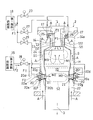
- FIG. 1 is a schematic longitudinal sectional view showing a gas turbine combustor according to a first embodiment of the present invention including a fuel supply system thereof.
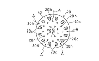
- FIG. 3 is an enlarged view of a part of FIG. 2. It is the III-III sectional view taken on the line of FIG. 3A.
- the gas turbine engine GT to which the gas turbine combustor is applied is a single can type as shown in FIG. 1, but may be a multi can type.
- the gas turbine engine GT includes a centrifugal compressor 1 that compresses air A taken in from an air inlet 1a, a combustor 2 that supplies fuel to the compressed air A and burns it, and combustion gas from the combustor 2 And a turbine 3 driven by The combustor 2 is disposed so as to protrude substantially in the radial direction with respect to the engine rotation axis C.
- Combustion gas generated in the combustor 2 is guided to the turbine 3 to rotate the turbine 3, and drives the centrifugal compressor 1 connected to the turbine 3 by the rotating shaft 4 and a load 7 that is a generator, for example. To do.
- the exhaust gas EG that has passed through the turbine 3 is discharged from the exhaust duct 8 to the outside.
- the combustor 2 includes a reverse flow in which the compressed air A and the combustion gas G introduced into the air passage 22 from the centrifugal compressor 1 (FIG. 1) flow in opposite directions in the combustor 2.
- It is a can type, and a substantially cylindrical combustion cylinder 9 is accommodated in a cylindrical housing H in a concentric arrangement.
- An air passage 22 for introducing the air A from the centrifugal compressor 1 is formed between the housing H and the combustion cylinder 9, and a combustion chamber 10 is formed inside the combustion cylinder 9.
- a burner unit (nozzle unit) 11 is attached to the top of the combustion cylinder 9.
- the burner unit 11 uses a hydrocarbon-based fuel containing 60% by volume or more of hydrocarbons as the first fuel F1.
- This hydrocarbon fuel is natural gas here.
- the hydrocarbon fuel includes, in addition to natural gas, gas fuel such as natural gas mixed with about 5% hydrogen, or liquid fuel such as kerosene and light oil.
- the burner unit 11 includes a main burner 12 that injects and burns a premixed gas M including a first fuel F1 for premixing supplied from a first fuel supply source 18 into a first combustion region S1 in the combustion chamber 10. And a pilot burner 13 for directly injecting the first fuel F1 into the first combustion region S1 and diffusing and burning it.
- the second fuel F2 and the first fuel for replenishment supplied from the second fuel supply source 19 to the second combustion region S2 downstream of the first combustion region S1 in the combustion chamber 10 are provided.
- a reheating burner 20 is provided that combusts both the first fuel F1 from the supply source 18 by premixing with the air A and injecting it.
- Each reheating burner 20 traverses the air passage 22 between the housing H and the combustion cylinder 9, and a plurality, for example, 2 to 12 of them are provided at equal intervals in the circumferential direction of the combustion cylinder 9.
- the second fuel F2 a gas having a composition different from that of the first fuel F1 and containing hydrogen at a concentration exceeding the stable combustion limit concentration, for example, a concentration exceeding 10% by volume is used.
- the hydrogen concentration of the second fuel F2 is preferably 20% by volume or more, and more preferably 30% by volume or more.
- This hydrogen-containing gas is, for example, hydrogen gas alone (100% by volume) or a gas obtained by mixing hydrogen gas with an inert gas such as methane gas, propane gas, or nitrogen.
- the main burner 12 is disposed so as to surround the outer periphery of the cylindrical pilot burner 13.
- the main burner 12 has an annular outer wall 121 having an L-shaped cross section and an annular inner wall 122, and a premixing passage 14 is formed between the outer wall 121 and the inner wall 122.
- the upstream end of the premixing passage 14 opens outward in the radial direction, and a plurality of main fuel nozzles 17 are equidistantly spaced in the circumferential direction of the main burner 12 outward of the opened annular air inlet 14a. Is arranged in.
- a plurality of fuel injection holes (not shown) for injecting the first fuel F1 toward the air intake port 14a are formed in a portion of the main fuel nozzle 17 facing the air intake port 14a, and the air intake port 14a. Is provided with a swirler 25 that swirls the inflowing air to promote premixing with the first fuel F1.
- the diffusion combustion type pilot burner 13 is disposed in the inner space of the inner wall 122.
- the follow-up burner 20 is formed by connecting a fuel introduction block 20a and an air-fuel mixture injection cylinder 20b with a plurality of guide pieces 20c to each other, and is not shown in the housing H.
- the tip of the air-fuel mixture injection cylinder part 20 b is inserted through an insertion hole 41 provided in the combustion cylinder 9 and protrudes into the combustion chamber 10.
- An air inlet 43 provided with a guide piece 20c is formed between the collar 20ba of the air-fuel mixture injection cylinder 20b and the bottom wall 20n of the fuel introduction block 20a.
- the air inlet 43 communicates with the premixing chamber 21 formed by the inner peripheral surface of the air-fuel mixture injection cylinder portion 20b and the outer surface of the bottom wall 20n.
- the fuel introduction block 20 a includes a first fuel introduction passage 20 d for introducing the first fuel F 1 from the first fuel supply source 18 from the radially outer side of the burner 2, and a second fuel from the second fuel supply source 19.
- a second fuel introduction passage 20e for introducing F2 from the radially outer side of the combustor 2, an annular first fuel chamber 20f for storing the first fuel F1 from the first fuel introduction passage 20d, and a second fuel introduction passage.
- a cylindrical second fuel chamber 20g for storing the second fuel F2 from 20e is provided.
- the fuel introduction block 20a further includes a first nozzle 20h comprising a plurality of small holes for injecting the first fuel F1 in the first fuel chamber 20f into the premixing chamber 21 on the bottom wall 20n, and a second fuel chamber 20g.
- a second nozzle 20i having a plurality of small holes for injecting the second fuel F2 into the premixing chamber 21;
- the guide piece 20c is arranged concentrically with the cylindrical air-fuel mixture injection cylinder portion 20b opposite to the fuel introduction block 20a, and in the vicinity of the outer peripheral edge of the fuel introduction block 20a in the circumferential direction as shown in FIG. 3B.
- a plurality (for example, 12) are provided at equal intervals.
- the first nozzle 20h of the fuel introduction block 20a is located slightly between the adjacent two guide pieces 20c and slightly closer to the axis C1 of the fuel introduction block 20a than the guide pieces 20c. Accordingly, the first fuel F1 shown in FIG. 3A is injected from the first nozzle 20h toward the air flow of the compressed air A flowing in from the air inlet 43.
- the second fuel F2 is injected toward the central portion of the premixing chamber 21 in the direction of the axis C1. Thereby, the smooth mixing of the first fuel F1 and the second fuel F2 and the compressed air A is promoted. Since the compressed air A flowing in from the air inlet 43 is deflected by 90 ° after passing through the guide piece 20c, turbulent flow is generated, thereby promoting mixing with the first fuel F1 and the second fuel F2.
- the flow rate of the first fuel F1 supplied from the first fuel supply source 18 shown in FIG. 2 is adjusted by the first fuel control valve 23, and then from the main fuel nozzle 17 to the air intake port 14a of the premixing passage 14. It is injected towards.
- the injected first fuel F1 is introduced into the premixing passage 14 while being swirled by the swirler 25 together with the compressed air A flowing from the air passage 22 into the air intake port 14a.
- the gas is premixed while flowing, and is ejected from the annular premixed gas outlet 24 into the combustion chamber 10 as the premixed gas M1.
- the first fuel control valve 23 When the gas turbine engine GT is started, the first fuel control valve 23 is closed, only the second fuel control valve 27 is opened, and the first fuel F1 of the first fuel supply source 18 turns the second fuel control valve 27 on. Then, the fuel is injected from the pilot burner 13 into the combustion chamber 10 and diffused and burned by ignition by a spark plug (not shown). During normal operation, while continuing the supply of the first fuel F1 from the pilot burner 13, the premixed gas M1 injected from the main burner 12 into the combustion chamber 10 is premixed and burned using the flame as a seed flame. In the upstream portion of the combustion chamber 10, a first combustion region S1 is formed. The main burner 12 and the pilot burner 13 are controlled so that the air-fuel ratio (air flow rate / fuel flow rate) becomes a preferable predetermined value.
- This first combustion region S1 is capable of reducing NOx soot, CO and the like by performing lean premixed combustion of the first fuel F1, and a hydrocarbon having a relatively low combustion speed in the main burner 12 for premixed combustion. Since the first fuel F1 of the system is supplied, good low emission performance can be maintained because no backfire occurs.
- a second combustion region S ⁇ b> 2 for premixing and burning the premixed gas M ⁇ b> 2 injected from the additional burner 20 is formed on the downstream side of the first combustion region S ⁇ b> 1.
- the reheating burner 20 is supplied from the second fuel supply source 19 through the third fuel control valve 28, and from the first fuel supply source 18 through the fourth fuel control valve 29. Both of the one fuel F1 is premixed with the compressed air A to generate a premixed gas M2, which is supplied to the second combustion region S2.
- the second combustion region S2 is formed in order to expand the operating range to the high output side according to the fluctuation of the operating load of the gas turbine engine GT, and the increase in the operating load of the gas turbine engine GT is a constant value.
- both the third fuel control valve 28 and the fourth fuel control valve 29 in FIG. 2 are adjusted so as to open by an opening corresponding to the fluctuation of the operating load, and the second fuel supply source 19 or the second fuel control valve 29 is adjusted.
- a required amount of the second fuel F ⁇ b> 2 and the first fuel F ⁇ b> 1 are supplied from the one fuel supply source 18 to the reheating burner 20. As is apparent from FIG.
- the usage amount of the second fuel F2 also increases as the operating load of the engine GT increases, so that the hydrogen gas that is not sufficiently utilized at that time at the high load is removed from the combustor 2. It can be used in large quantities as the second fuel F2. In this case, the flame holding performance of the first combustion region S1 is ensured by the main burner 12 and the pilot burner 13 regardless of the amount of the second fuel F2 supplied in the second combustion region S2.
- the first fuel F1 and the second fuel F2 respectively stored in the first fuel chamber 20f and the second fuel chamber 20i are injected into the premixing chamber 21 from the first nozzle 20h and the second nozzle 20i. After being mixed, it is premixed with the compressed air A flowing into the premixing chamber 21 from the air passage 22 through the air inlet 43. Thereby, in the premixing chamber 21, the 1st fuel F1 and the 2nd fuel F2 are fully mixed with the compressed air A introduced from the air passage 22, and the favorable premixed gas M2 is produced
- the premixed gas M2 is supplied from the mixed gas injection cylinder portion 20b to the second combustion region S2 in the combustion cylinder 9 and premixed and combusted.
- the second fuel F2 containing hydrogen gas having a high combustion speed can be burned at a low combustion temperature by introducing the compressed air A. Hydrogen gas with a large amount of NOx generated can be burned with low NOx.
- the reheating burner 20 is operated in a state where combustion by the main burner 12 and the pilot burner 13 is almost completed and high-temperature combustion gas G is generated, and therefore, the premixed gas injected from the reheating burner 20 is used.
- M2 the combustion reaction is stably promoted by the high-temperature combustion gas G without a flame holding mechanism. For this reason, there is no risk of backfire even when a fuel such as hydrogen is used as the second fuel F2.
- the second fuel F2 when the second fuel F2 is insufficient, it can be coped with by adding the first fuel F1.
- the fourth fuel control valve 29 is opened to open the first fuel when the second fuel F2 is insufficient due to the operation stop of the chemical plant.
- the first fuel F1 of the supply source 18 can be supplied from the reheating burner 20 to the second combustion region S2, and the required high output operation can be maintained.
- the backfire is generated from a relatively low speed place such as a boundary layer of the burner wall or a backflow area.
- the reheating burner 20 does not require a flame holding mechanism and does not include a swirler or a flame holder that generates a reverse flow region, and therefore has extremely high resistance to back fire from the reverse flow region. .
- the fuel concentration in the vicinity of the boundary layer that is, in the vicinity of the inner peripheral surface of the air-fuel mixture injection cylinder portion 20 by disposing the fuel injection holes of the additional burner 20, the reverse from the boundary layer generated in the vicinity of the inner peripheral surface Resistance to fire can be increased.
- the reheating burner 20 of this embodiment it is possible to use a relatively high concentration of hydrogen gas as fuel without backfire, while adopting a lean premixed combustion method. .
- FIG. 5 shows a second embodiment of the present invention.
- the gas turbine combustor 2A of the second embodiment is different from the gas turbine combustor 2 of FIG. 2 only in the configuration of the reheating burner 20A. That is, the reheating burner 20A directly introduces the mixed fuel into the mixing chamber 20j without storing the first fuel F1 from the first fuel introduction passage 20d and the second fuel F2 from the second fuel introduction passage 20f. Generate.
- the mixed fuel is injected from the mixing chamber 20j through the third nozzle 20k to the premixing chamber 21, and is premixed with the compressed air A flowing in from the air passage 22 to generate the premixed gas M2.
- the premixing chamber 21 is formed between the inner surface of the air-fuel mixture injection cylinder portion 20b and the bottom wall 20n of the fuel introduction block 20a that are coupled to each other via a plurality of guide pieces 20c. ing.
- the first fuel F1 and the second fuel F2 are temporarily stored in the individual first fuel chamber 20f and the second fuel chamber 20g, respectively, and then premixed to introduce the compressed air A While the first fuel F1 and the second fuel F2 are injected into the chamber 21 to generate the premixed gas M, in the second embodiment, the first fuel F1 and the second fuel F2 are fed into the mixing chamber 20j. After the introduction and generation of the mixed fuel in advance, the mixed fuel is injected into the premixing chamber 21 to generate the premixed gas M2. Therefore, as a result of promoting the mixing of the two fuels F1, F2, a more uniform premixed gas M2 is obtained.
- FIG. 6 shows a third embodiment of the present invention.
- the gas turbine combustor 2B of the third embodiment is different from the gas turbine combustor 2 of FIG. 2 in that the reheating burner 20B of FIG. 6 is provided separately for the first fuel F1 and the second fuel F2.
- the first burner 201 and the second burner 202 are arranged in two stages.
- the first burner 201 introduces the fuel chamber 20m for introducing the first fuel F1 from the single first introduction passage 20i, and introduces the first fuel F1 in the fuel chamber 20m from the third nozzle 20k to generate the compressed air A and the preliminary fuel A1.
- a premixing chamber 21 for mixing.
- the second burner 202 has the same structure, and the second fuel F2 is introduced into the fuel chamber 20m from the second fuel introduction passage 20p.
- the first fuel F1 is supplied to the first burner 201 via the fourth fuel control valve 29, and the second fuel F2 is supplied to the second burner 202 via the third fuel control valve 28.
- the first additional fuel supply passage 31 for supplying the first fuel F1 is branched from the upstream side of the first fuel control valve 23 in the main fuel supply passage 30 provided with the first fuel control valve 23.
- the fifth fuel control valve 32 is opened, and the first fuel F1 of the first fuel supply source 18 is supplied to the second fuel through the check valve 33.
- the first fuel F 1 and the second fuel F 2 from the second fuel supply source 19 are mixed by the mixer 34 and supplied to the second burner 202.
- the first additional fuel supply passage 31 is connected to the main fuel supply passage 30 on the upstream side of the first fuel control valve 23, the adjustment of the first fuel control valve 23 is performed. Regardless of the fluctuation in the pressure of the main fuel supply passage 30 accompanying the above, the required amount of the first fuel F1 can always be stably supplied to the additional burner 20B.
- FIG. 7 shows a fourth embodiment of the present invention.
- the gas turbine combustor 2C according to the fourth embodiment includes a plurality of reheating burners 20C in FIG. 7 having the same structure as the first burner 201 and the second burner 202 provided in the third embodiment in FIG.
- a pilot burner 13A that is provided and capable of supplying the second fuel F2 is provided.
- the second fuel F2 is introduced into the pilot fuel supply passage 37 for supplying the first fuel F1 to the pilot burner 13A through the second fuel control valve 27 and the check valve 38 through the sixth fuel control valve 39 when the main burner 12 is operated.
- the pilot sub passage 40 is connected.
- the check valve 38 allows only the flow of the first fuel F1 to the pilot burner 13A and the additional burner 20B.
- the gas turbine combustor 2C is provided with a fifth fuel control valve 32, a check valve 33, and a mixer 34 equivalent to those provided in the third embodiment (FIG. 6).
- the second fuel F2 containing hydrogen gas is the sixth fuel control. Since the fuel is supplied to the pilot burner 13A through the valve 39, the combustion in the pilot burner 13A is stabilized by the hydrogen gas having a high combustion temperature.
- Combustor 10 Combustor 12 Main burner 13, 13A Pilot burner 14 Premix passage 20, 20A, 20B Reheating burner 23 First fuel control valve 30 Main fuel supply passage 31 First additional fuel supply Passage 37 Pilot fuel supply passage 40 Pilot sub-passage S1 First combustion region S2 Second combustion region 201 First burner 202 Second burner M1, M2 Premixed gas
Landscapes
- Engineering & Computer Science (AREA)
- Chemical & Material Sciences (AREA)
- Combustion & Propulsion (AREA)
- Mechanical Engineering (AREA)
- General Engineering & Computer Science (AREA)
Abstract
Description
10 燃焼器
12 メインバーナ
13、13A パイロットバーナ
14 予混合通路
20、20A、20B 追焚きバーナ
23 第1燃料制御弁
30 メイン燃料供給通路
31 第1追焚き燃料供給通路
37 パイロット燃料供給通路
40 パイロットサブ通路
S1 第1燃焼領域
S2 第2燃焼領域
201 第1バーナ
202 第2バーナ
M1、M2 予混合気
Claims (7)
- 燃焼室内の第1燃焼領域に第1燃料を含む予混合気を供給して燃焼させるメインバーナと、
前記燃焼室内の前記第1燃焼領域よりも下流の第2燃焼領域に、前記第1燃料とは異なる組成の第2燃料を含む予混合気を供給して燃焼させる追焚きバーナとを備え、
前記第1燃料は炭化水素系であり、前記第2燃料は水素の安定燃焼限界濃度を超える濃度で水素を含有するガスであるガスタービン燃焼器。 - 請求項1に記載のガスタービン燃焼器において、前記追焚きバーナは、前記第1燃料および前記第2燃料を空気と予混合して前記第2燃焼領域に供給する予混合バーナであるガスタービン燃焼器。
- 請求項2に記載のガスタービン燃焼器において、前記追焚きバーナは、空気を導入する予混合室と、前記予混合室に前記第1燃料を噴射する第1ノズルと、前記予混合室に前記第2燃料を噴射する第2ノズルとを有するガスタービン燃焼器。
- 請求項2に記載のガスタービン燃焼器において、前記追焚きバーナは、前記第1燃料と前記第2燃料とが導入される混合室と、前記混合室からの混合燃料を空気と予混合する前記予混合室とを有するガスタービン燃焼器。
- 請求項2に記載のガスタービン燃焼器において、前記追焚きバーナは、前記第1燃料を空気と予混合して噴射する第1バーナと、前記第2燃料を空気と予混合して噴射する第2バーナとを有するガスタービン燃焼器。
- 請求項2から4のいずれか一項に記載のガスタービン燃焼器において、前記第1燃料を前記メインバーナに供給するメイン燃料供給通路に第1燃料制御弁が設けられ、前記追焚きバーナに前記第1燃料を供給する第1追焚き燃料供給通路が、前記メイン燃料供給通路における前記第1燃料制御弁の上流側から分岐しているガスタービン燃焼器。
- 請求項1から6のいずれか一項に記載のガスタービン燃焼器において、前記第1燃料を第1燃焼領域に噴射して拡散燃焼させるパイロットバーナを備え、前記第1燃料を前記パイロットバーナに供給するパイロット燃料供給通路に、前記メインバーナの作動時に前記第2燃料を導入するパイロットサブ通路を有するガスタービン燃焼器。
Priority Applications (8)
| Application Number | Priority Date | Filing Date | Title |
|---|---|---|---|
| PCT/JP2014/065657 WO2015037295A1 (ja) | 2014-06-12 | 2014-06-12 | マルチ燃料対応のガスタービン燃焼器 |
| CN201480002116.7A CN105452775B (zh) | 2014-06-12 | 2014-06-12 | 适合多种燃料的燃气轮机燃烧器 |
| CA2885287A CA2885287C (en) | 2014-06-12 | 2014-06-12 | Multifuel gas turbine combustor |
| JP2015508912A JP5759651B1 (ja) | 2014-06-12 | 2014-06-12 | マルチ燃料対応のガスタービン燃焼器 |
| EP14844741.0A EP2902708B1 (en) | 2014-06-12 | 2014-06-12 | Multi-fuel-supporting gas-turbine combustor |
| EP15168221.8A EP2955445B1 (en) | 2014-06-12 | 2014-06-12 | Multifuel gas turbine combustor |
| US14/421,065 US9400113B2 (en) | 2014-06-12 | 2014-06-12 | Multifuel gas turbine combustor |
| US14/620,874 US9638423B2 (en) | 2014-06-12 | 2015-02-12 | Multifuel gas turbine combustor with fuel mixing chamber and supplemental burner |
Applications Claiming Priority (1)
| Application Number | Priority Date | Filing Date | Title |
|---|---|---|---|
| PCT/JP2014/065657 WO2015037295A1 (ja) | 2014-06-12 | 2014-06-12 | マルチ燃料対応のガスタービン燃焼器 |
Related Child Applications (2)
| Application Number | Title | Priority Date | Filing Date |
|---|---|---|---|
| US14/421,065 A-371-Of-International US9400113B2 (en) | 2014-06-12 | 2014-06-12 | Multifuel gas turbine combustor |
| US14/620,874 Continuation US9638423B2 (en) | 2014-06-12 | 2015-02-12 | Multifuel gas turbine combustor with fuel mixing chamber and supplemental burner |
Publications (1)
| Publication Number | Publication Date |
|---|---|
| WO2015037295A1 true WO2015037295A1 (ja) | 2015-03-19 |
Family
ID=52665420
Family Applications (1)
| Application Number | Title | Priority Date | Filing Date |
|---|---|---|---|
| PCT/JP2014/065657 WO2015037295A1 (ja) | 2014-06-12 | 2014-06-12 | マルチ燃料対応のガスタービン燃焼器 |
Country Status (6)
| Country | Link |
|---|---|
| US (2) | US9400113B2 (ja) |
| EP (2) | EP2955445B1 (ja) |
| JP (1) | JP5759651B1 (ja) |
| CN (1) | CN105452775B (ja) |
| CA (1) | CA2885287C (ja) |
| WO (1) | WO2015037295A1 (ja) |
Cited By (4)
| Publication number | Priority date | Publication date | Assignee | Title |
|---|---|---|---|---|
| WO2017005694A1 (en) * | 2015-07-06 | 2017-01-12 | Siemens Aktiengesellschaft | Burner for a gas turbine and method for operating the burner |
| JP2020165399A (ja) * | 2019-03-29 | 2020-10-08 | 三菱重工業株式会社 | 燃焼器、燃焼器システム、及びガスタービンシステム |
| US10837641B2 (en) | 2014-12-25 | 2020-11-17 | Kawasaki Jukogyo Kabushiki Kaisha | Burner, combustor, and gas turbine |
| US11132616B2 (en) | 2016-09-20 | 2021-09-28 | Kabushiki Kaisha Toshiba | Characteristic value estimation device and characteristic value estimation method |
Families Citing this family (39)
| Publication number | Priority date | Publication date | Assignee | Title |
|---|---|---|---|---|
| WO2015037295A1 (ja) | 2014-06-12 | 2015-03-19 | 川崎重工業株式会社 | マルチ燃料対応のガスタービン燃焼器 |
| US20160047317A1 (en) * | 2014-08-14 | 2016-02-18 | General Electric Company | Fuel injector assemblies in combustion turbine engines |
| JP6516996B2 (ja) * | 2014-10-10 | 2019-05-22 | 川崎重工業株式会社 | 燃焼器及びガスタービンエンジン |
| US10060629B2 (en) * | 2015-02-20 | 2018-08-28 | United Technologies Corporation | Angled radial fuel/air delivery system for combustor |
| EP3220050A1 (en) * | 2016-03-16 | 2017-09-20 | Siemens Aktiengesellschaft | Burner for a gas turbine |
| EP3301374A1 (en) * | 2016-09-29 | 2018-04-04 | Siemens Aktiengesellschaft | A pilot burner assembly with pilot-air supply |
| US10508811B2 (en) * | 2016-10-03 | 2019-12-17 | United Technologies Corporation | Circumferential fuel shifting and biasing in an axial staged combustor for a gas turbine engine |
| CN107023854B (zh) * | 2016-12-26 | 2019-08-23 | 南方科技大学 | 一种径向进气旋流式细管预混燃油喷嘴 |
| US10415833B2 (en) | 2017-02-16 | 2019-09-17 | General Electric Company | Premixer for gas turbine combustor |
| US11137144B2 (en) * | 2017-12-11 | 2021-10-05 | General Electric Company | Axial fuel staging system for gas turbine combustors |
| DE102018125848A1 (de) * | 2018-10-18 | 2020-04-23 | Man Energy Solutions Se | Brennkammer einer Gasturbine, Gasturbine und Verfahren zum Betreiben derselben |
| US11156164B2 (en) | 2019-05-21 | 2021-10-26 | General Electric Company | System and method for high frequency accoustic dampers with caps |
| US11174792B2 (en) | 2019-05-21 | 2021-11-16 | General Electric Company | System and method for high frequency acoustic dampers with baffles |
| KR102152420B1 (ko) * | 2019-08-23 | 2020-09-07 | 두산중공업 주식회사 | 연소기, 이를 포함하는 가스 터빈, 및 연소기의 구동 방법 |
| US11506390B2 (en) * | 2019-12-06 | 2022-11-22 | Raytheon Technologies Corporation | Multi-fuel bluff-body piloted high-shear injector and method of using same |
| US12098678B2 (en) | 2020-01-08 | 2024-09-24 | Rtx Corporation | Method of using a primary fuel to pilot liquid fueled combustors |
| CN115135931B (zh) * | 2020-02-19 | 2024-06-28 | 三菱重工发动机和增压器株式会社 | 燃烧器以及燃气轮机 |
| US12044174B2 (en) * | 2020-10-14 | 2024-07-23 | King Abdullah University Of Science And Technology | Adjustable fuel injector for flame dynamics control |
| GB2602037A (en) * | 2020-12-16 | 2022-06-22 | Siemens Energy Global Gmbh & Co Kg | Method of operating a combustor for a gas turbine |
| CN112815356B (zh) * | 2020-12-31 | 2022-07-15 | 哈尔滨工程大学 | 一种可自适应调节的富氢燃料低排放微焰燃烧室 |
| KR20230128100A (ko) * | 2021-02-25 | 2023-09-01 | 에어 프로덕츠 앤드 케미칼스, 인코오포레이티드 | 가스 터빈 시스템의 향상된 연소 안정성을 위한 수소주입 |
| CN116917667A (zh) | 2021-02-25 | 2023-10-20 | 气体产品与化学公司 | 用于增强燃气轮机系统中的燃烧稳定性的氢气喷射 |
| US11808457B2 (en) | 2021-02-25 | 2023-11-07 | Air Products And Chemicals, Inc. | Hydrogen injection for enhanced combustion stability in gas turbine systems |
| US12066188B2 (en) | 2021-03-26 | 2024-08-20 | Rtx Corporation | Modular injector bolt for an engine |
| US11815025B2 (en) * | 2021-05-07 | 2023-11-14 | General Electric Company | Fuel nozzle |
| EP4116554B1 (en) * | 2021-07-05 | 2024-08-28 | Ansaldo Energia Switzerland AG | Method for operating a gas turbine and method for retrofitting a gas turbine |
| EP4116555A1 (en) * | 2021-07-05 | 2023-01-11 | Ansaldo Energia Switzerland AG | Operating method and retrofitting method for a gas turbine |
| US11940151B2 (en) | 2022-01-12 | 2024-03-26 | General Electric Company | Combustor with baffle |
| US11885498B2 (en) * | 2022-01-31 | 2024-01-30 | General Electric Company | Turbine engine with fuel system including a catalytic reformer |
| US12072101B2 (en) | 2022-02-18 | 2024-08-27 | Rtx Corporation | Fuel injector with splash plate for an engine |
| GB2602936B (en) * | 2022-04-20 | 2023-02-15 | Derwent Tech Ltd | Propulsion system |
| US12148312B2 (en) * | 2022-06-27 | 2024-11-19 | Rockwell Collins, Inc. | System and method for display of aircraft carbon savings |
| DE102022207492A1 (de) * | 2022-07-21 | 2024-02-01 | Rolls-Royce Deutschland Ltd & Co Kg | Düsenvorrichtung zur Zugabe zumindest eines gasförmigen Kraftstoffes und eines flüssigen Kraftstoffes, Set, Zuleitungssystem und Gasturbinenanordnung |
| US12018839B2 (en) | 2022-10-20 | 2024-06-25 | General Electric Company | Gas turbine engine combustor with dilution passages |
| KR102756078B1 (ko) * | 2022-12-06 | 2025-01-21 | 두산에너빌리티 주식회사 | 연소기 및 이를 포함하는 가스터빈 |
| US12158270B2 (en) | 2022-12-20 | 2024-12-03 | General Electric Company | Gas turbine engine combustor with a set of dilution passages |
| CN116428612A (zh) * | 2023-04-12 | 2023-07-14 | 南京航空航天大学 | 一种能够阻止回火现象发生的旋流器 |
| DE102023204572A1 (de) * | 2023-05-16 | 2024-11-21 | Rolls-Royce Deutschland Ltd & Co Kg | Brennkammermodul mit einer ringförmigen brennkammer |
| US12173898B1 (en) * | 2023-09-01 | 2024-12-24 | General Electric Company | Combustion section with a primary combustor and a set of secondary combustors |
Citations (6)
| Publication number | Priority date | Publication date | Assignee | Title |
|---|---|---|---|---|
| JPH07119491A (ja) * | 1993-10-27 | 1995-05-09 | Chugoku Electric Power Co Inc:The | Lng改質ガス燃焼ガスタービン複合発電プラント |
| JPH1172009A (ja) * | 1996-09-20 | 1999-03-16 | Toshiba Corp | 発電システム |
| US6237343B1 (en) * | 1998-05-02 | 2001-05-29 | Rolls-Royce Plc | Combustion chamber and a method of operation thereof |
| JP2010096488A (ja) * | 2008-10-20 | 2010-04-30 | General Electric Co <Ge> | 多段燃焼システム及び方法 |
| JP2010174767A (ja) * | 2009-01-30 | 2010-08-12 | Hitachi Ltd | ガスタービン,ガスタービンの制御装置及びガスタービンの点火制御方法 |
| WO2013043076A1 (en) * | 2011-09-22 | 2013-03-28 | General Electric Company | Combustor and method for supplying fuel to a combustor |
Family Cites Families (30)
| Publication number | Priority date | Publication date | Assignee | Title |
|---|---|---|---|---|
| JPH0359143A (ja) | 1989-07-27 | 1991-03-14 | Asahi Chem Ind Co Ltd | カットパイル織編物 |
| JPH04340020A (ja) | 1991-05-15 | 1992-11-26 | Mitsubishi Heavy Ind Ltd | ガスタービン燃焼器 |
| JP3012166B2 (ja) | 1995-02-01 | 2000-02-21 | 川崎重工業株式会社 | ガスタービン燃焼システム |
| JP3578852B2 (ja) | 1995-12-05 | 2004-10-20 | 東京瓦斯株式会社 | マルチバーナ式燃焼器の燃料供給システム及び該燃料供給システムを持つガスタービン |
| EP0831205B1 (en) | 1996-09-20 | 2004-05-12 | Kabushiki Kaisha Toshiba | Power generation system capable of separating and recovering carbon dioxide |
| JP3775718B2 (ja) | 2000-08-18 | 2006-05-17 | 財団法人電力中央研究所 | 発電プラントおよびその運転方法 |
| US6868676B1 (en) | 2002-12-20 | 2005-03-22 | General Electric Company | Turbine containing system and an injector therefor |
| JP4400314B2 (ja) | 2004-06-02 | 2010-01-20 | 株式会社日立製作所 | ガスタービン燃焼器及びガスタービン燃焼器の燃料供給方法 |
| JP4670035B2 (ja) * | 2004-06-25 | 2011-04-13 | 独立行政法人 宇宙航空研究開発機構 | ガスタービン燃焼器 |
| JP2007113888A (ja) | 2005-10-24 | 2007-05-10 | Kawasaki Heavy Ind Ltd | ガスタービンエンジンの燃焼器構造 |
| JP5086001B2 (ja) | 2007-08-23 | 2012-11-28 | 川崎重工業株式会社 | ガスタービン燃焼装置 |
| US8387398B2 (en) | 2007-09-14 | 2013-03-05 | Siemens Energy, Inc. | Apparatus and method for controlling the secondary injection of fuel |
| EP2257736B1 (de) * | 2008-03-07 | 2015-11-25 | Alstom Technology Ltd | Verfahren zum erzeugen von heissgas |
| EP2107300A1 (en) | 2008-04-01 | 2009-10-07 | Siemens Aktiengesellschaft | Swirler with gas injectors |
| US8701382B2 (en) | 2009-01-07 | 2014-04-22 | General Electric Company | Late lean injection with expanded fuel flexibility |
| JP2010196488A (ja) * | 2009-02-23 | 2010-09-09 | Mitsubishi Motors Corp | 可変動弁装置付エンジン |
| JP4797079B2 (ja) | 2009-03-13 | 2011-10-19 | 川崎重工業株式会社 | ガスタービン燃焼器 |
| JP5075900B2 (ja) * | 2009-09-30 | 2012-11-21 | 株式会社日立製作所 | 水素含有燃料対応燃焼器および、その低NOx運転方法 |
| US20110091829A1 (en) * | 2009-10-20 | 2011-04-21 | Vinayak Barve | Multi-fuel combustion system |
| JP5537895B2 (ja) | 2009-10-21 | 2014-07-02 | 川崎重工業株式会社 | ガスタービン燃焼器 |
| US8650851B2 (en) * | 2010-01-05 | 2014-02-18 | General Electric Company | Systems and methods for controlling fuel flow within a machine |
| JP5084847B2 (ja) | 2010-01-13 | 2012-11-28 | 株式会社日立製作所 | ガスタービン燃焼器 |
| JP5649949B2 (ja) * | 2010-12-28 | 2015-01-07 | 川崎重工業株式会社 | 燃焼装置 |
| JP5393745B2 (ja) | 2011-09-05 | 2014-01-22 | 川崎重工業株式会社 | ガスタービン燃焼器 |
| US9200808B2 (en) * | 2012-04-27 | 2015-12-01 | General Electric Company | System for supplying fuel to a late-lean fuel injector of a combustor |
| US9366432B2 (en) * | 2012-05-17 | 2016-06-14 | Capstone Turbine Corporation | Multistaged lean prevaporizing premixing fuel injector |
| US9291098B2 (en) * | 2012-11-14 | 2016-03-22 | General Electric Company | Turbomachine and staged combustion system of a turbomachine |
| EP2933561A4 (en) | 2012-12-13 | 2016-08-24 | Kawasaki Heavy Ind Ltd | MULTI-FACTORY GAS TURBINE CHAMBER |
| US9377202B2 (en) | 2013-03-15 | 2016-06-28 | General Electric Company | System and method for fuel blending and control in gas turbines |
| WO2015037295A1 (ja) | 2014-06-12 | 2015-03-19 | 川崎重工業株式会社 | マルチ燃料対応のガスタービン燃焼器 |
-
2014
- 2014-06-12 WO PCT/JP2014/065657 patent/WO2015037295A1/ja active Application Filing
- 2014-06-12 JP JP2015508912A patent/JP5759651B1/ja active Active
- 2014-06-12 US US14/421,065 patent/US9400113B2/en active Active
- 2014-06-12 CA CA2885287A patent/CA2885287C/en active Active
- 2014-06-12 CN CN201480002116.7A patent/CN105452775B/zh active Active
- 2014-06-12 EP EP15168221.8A patent/EP2955445B1/en active Active
- 2014-06-12 EP EP14844741.0A patent/EP2902708B1/en active Active
-
2015
- 2015-02-12 US US14/620,874 patent/US9638423B2/en active Active
Patent Citations (6)
| Publication number | Priority date | Publication date | Assignee | Title |
|---|---|---|---|---|
| JPH07119491A (ja) * | 1993-10-27 | 1995-05-09 | Chugoku Electric Power Co Inc:The | Lng改質ガス燃焼ガスタービン複合発電プラント |
| JPH1172009A (ja) * | 1996-09-20 | 1999-03-16 | Toshiba Corp | 発電システム |
| US6237343B1 (en) * | 1998-05-02 | 2001-05-29 | Rolls-Royce Plc | Combustion chamber and a method of operation thereof |
| JP2010096488A (ja) * | 2008-10-20 | 2010-04-30 | General Electric Co <Ge> | 多段燃焼システム及び方法 |
| JP2010174767A (ja) * | 2009-01-30 | 2010-08-12 | Hitachi Ltd | ガスタービン,ガスタービンの制御装置及びガスタービンの点火制御方法 |
| WO2013043076A1 (en) * | 2011-09-22 | 2013-03-28 | General Electric Company | Combustor and method for supplying fuel to a combustor |
Non-Patent Citations (1)
| Title |
|---|
| See also references of EP2902708A4 * |
Cited By (8)
| Publication number | Priority date | Publication date | Assignee | Title |
|---|---|---|---|---|
| US10837641B2 (en) | 2014-12-25 | 2020-11-17 | Kawasaki Jukogyo Kabushiki Kaisha | Burner, combustor, and gas turbine |
| DE112015005803B4 (de) | 2014-12-25 | 2022-08-25 | Kawasaki Jukogyo Kabushiki Kaisha | Brenner, Brennkammer und Gasturbine |
| WO2017005694A1 (en) * | 2015-07-06 | 2017-01-12 | Siemens Aktiengesellschaft | Burner for a gas turbine and method for operating the burner |
| CN107735618A (zh) * | 2015-07-06 | 2018-02-23 | 西门子股份公司 | 用于燃气涡轮的燃烧器和操作燃烧器的方法 |
| US10941940B2 (en) | 2015-07-06 | 2021-03-09 | Siemens Energy Global GmbH & Co. KG | Burner for a gas turbine and method for operating the burner |
| US11132616B2 (en) | 2016-09-20 | 2021-09-28 | Kabushiki Kaisha Toshiba | Characteristic value estimation device and characteristic value estimation method |
| JP2020165399A (ja) * | 2019-03-29 | 2020-10-08 | 三菱重工業株式会社 | 燃焼器、燃焼器システム、及びガスタービンシステム |
| JP7234009B2 (ja) | 2019-03-29 | 2023-03-07 | 三菱重工業株式会社 | 燃焼器システム、及びガスタービンシステム |
Also Published As
| Publication number | Publication date |
|---|---|
| CA2885287C (en) | 2016-08-30 |
| EP2902708B1 (en) | 2017-02-01 |
| CN105452775A (zh) | 2016-03-30 |
| US9638423B2 (en) | 2017-05-02 |
| EP2902708A4 (en) | 2015-10-07 |
| US20160033131A1 (en) | 2016-02-04 |
| CN105452775B (zh) | 2017-09-29 |
| US9400113B2 (en) | 2016-07-26 |
| EP2955445B1 (en) | 2019-11-27 |
| JP5759651B1 (ja) | 2015-08-05 |
| JPWO2015037295A1 (ja) | 2017-03-02 |
| CA2885287A1 (en) | 2015-03-19 |
| EP2955445A1 (en) | 2015-12-16 |
| US20150362194A1 (en) | 2015-12-17 |
| EP2902708A1 (en) | 2015-08-05 |
Similar Documents
| Publication | Publication Date | Title |
|---|---|---|
| JP5759651B1 (ja) | マルチ燃料対応のガスタービン燃焼器 | |
| JP6033887B2 (ja) | マルチ燃料対応のガスタービン燃焼器 | |
| CN107110506B (zh) | 烧嘴、燃烧器以及燃气轮机 | |
| US8539773B2 (en) | Premixed direct injection nozzle for highly reactive fuels | |
| JP2009108858A (ja) | 燃焼器内でシンガスを燃焼させるための方法及び装置 | |
| JP2010159758A (ja) | 燃料柔軟性を拡大した遅延希薄噴射 | |
| WO2016072423A1 (ja) | バーナ、燃焼器、及びガスタービン | |
| US8459985B2 (en) | Method and burner arrangement for the production of hot gas, and use of said method | |
| JP2010159956A (ja) | 気流分割の調節による希薄遅延噴射 | |
| JP2010159955A (ja) | 燃料の融通性を得るための遅延希薄噴射 | |
| JP2010085087A5 (ja) | ||
| CN112594734B (zh) | 燃气轮机燃烧器 | |
| CN105276619B (zh) | 适合多种燃料的燃气轮机燃烧器 | |
| JP5993046B2 (ja) | マルチ燃料対応のガスタービン燃焼器 | |
| JP2010054087A (ja) | ガスタービン燃焼器およびガスタービン燃焼器の運転方法 | |
| US20120047907A1 (en) | Method for operating a combustion chamber and combustion chamber | |
| JP7210119B2 (ja) | 工業炉 | |
| JP7585288B2 (ja) | バーナ及び当該バーナを有する燃焼器 | |
| JP2016109307A (ja) | ガスタービン用燃焼器、及びガスタービン |
Legal Events
| Date | Code | Title | Description |
|---|---|---|---|
| WWE | Wipo information: entry into national phase |
Ref document number: 201480002116.7 Country of ref document: CN |
|
| WWE | Wipo information: entry into national phase |
Ref document number: 14421065 Country of ref document: US |
|
| ENP | Entry into the national phase |
Ref document number: 2015508912 Country of ref document: JP Kind code of ref document: A |
|
| WWE | Wipo information: entry into national phase |
Ref document number: 2885287 Country of ref document: CA |
|
| REEP | Request for entry into the european phase |
Ref document number: 2014844741 Country of ref document: EP |
|
| WWE | Wipo information: entry into national phase |
Ref document number: 2014844741 Country of ref document: EP |
|
| 121 | Ep: the epo has been informed by wipo that ep was designated in this application |
Ref document number: 14844741 Country of ref document: EP Kind code of ref document: A1 |
|
| NENP | Non-entry into the national phase |
Ref country code: DE |