EP3220050A1 - Burner for a gas turbine - Google Patents
Burner for a gas turbine Download PDFInfo
- Publication number
- EP3220050A1 EP3220050A1 EP16160740.3A EP16160740A EP3220050A1 EP 3220050 A1 EP3220050 A1 EP 3220050A1 EP 16160740 A EP16160740 A EP 16160740A EP 3220050 A1 EP3220050 A1 EP 3220050A1
- Authority
- EP
- European Patent Office
- Prior art keywords
- fuel
- swirler
- burner
- air
- chamber
- Prior art date
- Legal status (The legal status is an assumption and is not a legal conclusion. Google has not performed a legal analysis and makes no representation as to the accuracy of the status listed.)
- Withdrawn
Links
Images

Classifications
-
- F—MECHANICAL ENGINEERING; LIGHTING; HEATING; WEAPONS; BLASTING
- F23—COMBUSTION APPARATUS; COMBUSTION PROCESSES
- F23R—GENERATING COMBUSTION PRODUCTS OF HIGH PRESSURE OR HIGH VELOCITY, e.g. GAS-TURBINE COMBUSTION CHAMBERS
- F23R3/00—Continuous combustion chambers using liquid or gaseous fuel
- F23R3/02—Continuous combustion chambers using liquid or gaseous fuel characterised by the air-flow or gas-flow configuration
- F23R3/04—Air inlet arrangements
- F23R3/10—Air inlet arrangements for primary air
- F23R3/12—Air inlet arrangements for primary air inducing a vortex
- F23R3/14—Air inlet arrangements for primary air inducing a vortex by using swirl vanes
-
- F—MECHANICAL ENGINEERING; LIGHTING; HEATING; WEAPONS; BLASTING
- F23—COMBUSTION APPARATUS; COMBUSTION PROCESSES
- F23R—GENERATING COMBUSTION PRODUCTS OF HIGH PRESSURE OR HIGH VELOCITY, e.g. GAS-TURBINE COMBUSTION CHAMBERS
- F23R3/00—Continuous combustion chambers using liquid or gaseous fuel
- F23R3/28—Continuous combustion chambers using liquid or gaseous fuel characterised by the fuel supply
- F23R3/34—Feeding into different combustion zones
- F23R3/346—Feeding into different combustion zones for staged combustion
-
- F—MECHANICAL ENGINEERING; LIGHTING; HEATING; WEAPONS; BLASTING
- F23—COMBUSTION APPARATUS; COMBUSTION PROCESSES
- F23R—GENERATING COMBUSTION PRODUCTS OF HIGH PRESSURE OR HIGH VELOCITY, e.g. GAS-TURBINE COMBUSTION CHAMBERS
- F23R3/00—Continuous combustion chambers using liquid or gaseous fuel
- F23R3/28—Continuous combustion chambers using liquid or gaseous fuel characterised by the fuel supply
- F23R3/36—Supply of different fuels
-
- F—MECHANICAL ENGINEERING; LIGHTING; HEATING; WEAPONS; BLASTING
- F23—COMBUSTION APPARATUS; COMBUSTION PROCESSES
- F23R—GENERATING COMBUSTION PRODUCTS OF HIGH PRESSURE OR HIGH VELOCITY, e.g. GAS-TURBINE COMBUSTION CHAMBERS
- F23R2900/00—Special features of, or arrangements for continuous combustion chambers; Combustion processes therefor
- F23R2900/00002—Gas turbine combustors adapted for fuels having low heating value [LHV]
Definitions
- the present invention relates to a burner for a gas turbine, to a gas turbine and to a method for operating a burner of a gas turbine.
- Gas turbines are commonly used in industrial applications.
- the gas turbine may be operated in a DLE (dry low emission) combustion mode, wherein the gas turbine produces low emissions, especially low NOx emissions.
- DLE dry low emission
- combustion hardware for gas turbine (GT) engines is designed for a specific fuel (i.e. natural gas, diesel, syngas, landfill gas and other hydrocarbon fuels with varying Wobbe Index).
- a specific fuel i.e. natural gas, diesel, syngas, landfill gas and other hydrocarbon fuels with varying Wobbe Index.
- flashback flame burning on the combustor surface
- flameout engine shutdown
- combustion dynamics hardware integrity
- high pressure drop performance loss
- Low NOx-emission combustors utilize reduced peak flame temperatures within the combustor to limit the formation of thermal NOx through staging strategies such as lean premixed combustion. As combustion temperatures are decreased in low NOx applications, several other undesirable combustion phenomena become more prevalent and must be addressed. The low-NOx limit is often bounded by the onset of combustion instability in the form of Lean Blow Out (LBO) also known as flameout. Lean Blow Out occurs when the thermal energy generated by the burning fuel/air mixture is no longer sufficient to heat the incoming fuel-air mixture to the ignition point.
- LBO Lean Blow Out
- a burner for a gas turbine comprising a chamber for combusting a fuel mixture, a first injector for injecting a first fuel (in particular H 2 ) into the chamber, an downstream swirler for introducing a mixture of a second fuel (in particular CH 4 ) and air into the chamber, and a upstream swirler for introducing a mixture of a third fuel (in particular NH 3 ) different from the second fuel and further air into the chamber.
- the burner may be adapted to simultaneously burn the first fuel, the second fuel and the third fuel.
- the downstream swirler and the upstream swirler may be of a similar configuration/geometry but may have different dimensions.
- the upstream swirler may have a larger size than the downstream swirler.
- the upstream swirler may introduce a larger amount (e.g. per time) of the third fuel into the chamber than the downstream swirler introduces an amount (e.g. per time) of the second fuel into the chamber.
- the second fuel and the third fuel are different and may have different combustion properties and also different thermo-chemical properties, such as diffusivity, calorific value, ignition temperature, flame speed.
- the configurations (in particular relative configuration or dimensions) of the downstream and the upstream swirler may be selected. Further, the relative positioning of the downstream swirler and the upstream swirler in the burner may depend on the different combustion properties of the different fuels and may also depend on the relative amounts of the second fuel and the third fuel being introduced into the chamber during the operation of the burner.
- the burner may achieve a reliable combustion of the three different fuels and may also achieve relatively low NOx emissions.
- a controller may control the operation of the burner, wherein the controller in particular may adjust the mass flows of the first fuel, the second fuel and the third fuel and may also control the amount of air introduced via the downstream swirler and/or via the upstream swirler.
- a volume flow rate of the upstream swirler and/or a position of the upstream swirler relative to the downstream swirler is selected based on a combustion property of the third fuel, in particular relative to a combustion property of the second fuel, and/or based on a mass flow of the third fuel into the combustion chamber, in particular relative to a mass flow of the second fuel into the combustion chamber, wherein the volume flow rate of the upstream swirler is in particular between 2 and 5 times the volume flow rate of the downstream swirler.
- the combustion property of the fuel may include for example diffusivity, calorific value, ignition temperature, flame speed among others.
- the combustion properties of the second fuel and the third fuel may allow to optimally design the geometry and/or size of the downstream and upstream swirler.
- the downstream swirler and/or the upstream swirler may have a design of a so-called radial swirler which introduces air and the respective fuel using swirler vanes which guide the air into an inside of the respective swirler, wherein one or more injectors for the respective fuel are provided at the swirler vanes, in order to achieve a mixing of the air with the respective fuel.
- the downstream swirler and/or the upstream swirler may have substantially a cylindrical geometry and may at least partially surround the chamber of the burner, in particular a pre-chamber of the burner.
- the burner is adapted to simultaneously burn a second fuel together with a third fuel, the third fuel mass flow rate being between 70% and 97% of a total mass flow rate burned, wherein a calorific value of the second fuel is in particular between 1.2 and 5 times a calorific value of the third fuel, which may in particular comprises ammonia (NH 3
- a position of the downstream swirler is, in an axial direction away from the first injector (pilot burner), spaced apart from a position of the upstream swirler, in particular between 0.5 and 2 times a diameter of a prechamber of the combustion chamber.
- the upstream swirler may thus be closer (in the axial direction) located at the first injector from pilot burner than the downstream swirler.
- the third fuel introduced via the upstream swirler into the chamber of the burner may stream along a longer mixing path to reach a combustion region of the burner than the second fuel which is introduced via the downstream swirler.
- a larger amount of the third fuel is efficiently supported and also a lower calorific value relative to the calorific value of the second fuel may be accounted for.
- the first, the second and the third fuels flow rates, at least partially mixed with air, along flow paths having a first, second and third premixing length (L1, L2, L3), respectively from an injection location in the burner to a combustion region within the burner, wherein the burner is adapted such that the first premixing length is smaller than the second premixing length and the second premixing length is smaller than the third premixing length, wherein the first premixing length is in particular between 20 mm and 100 mm, wherein the second premixing length is in particular between 40 mm and 300 mm, wherein the third premixing length is in particular between 60 mm and 400 mm.
- L1, L2, L3 first, second and third premixing length
- the first fuel may have a highest calorific value
- the second fuel may have a medium calorific value
- the third fuel may have the lowest calorific value of all fuels used during operation of the burner.
- the downstream swirler comprises second injectors and the upstream swirler comprises third injectors for supplying the second and third fuels respectively, into the swirlers, wherein a diameter (e.g. inner pitch circle diameter) of the upstream swirler is in particular between 150 mm and 450 mm, wherein inner pitch circle diameter of the downstream swirler is in particular between 50 mm and 250 mm.
- a diameter e.g. inner pitch circle diameter
- the diameters of the upstream swirler and the downstream swirler may be selected based on an amount of the respective fuel introduced via the respective swirler into the chamber of the burner and may also be selected based on the respective calorific value (and/or other combustion properties) of the fuel. The more the mass flow per time is introduced via the respective swirler into the chamber, the larger the diameter of the respective swirler may be selected. Thereby, an efficient premixing within the respective swirler of the respective fuel with the air may be achieved before introducing the premixed fuel/air into the chamber of the burner.
- the swirler comprises plural swirler vanes, circumferentially spaced apart, for guiding air entering from radially outwards into the swirler radially inwards and partially in a circumferential direction
- the upstream swirler comprises plural further swirler vanes, circumferentially spaced apart, for guiding upstream air entering from radially outwards into the upstream swirler radially inwards and partially in a circumferential direction.
- the swirler vanes may comprise each a substantially flat or plane surface along which air introduced radially is guided towards inwards section of the swirler.
- the injectors may be formed as one, two or more holes within the surface of the swirler vane.
- the second injectors are arranged on the swirler vanes such as to partially mix the second fuel with the guided air
- the third injectors are arranged on the upstream swirler vanes such as to partially mix the third fuel with the guided further air, wherein in particular two or more injectors in the swirlers are formed at each of the swirler vanes.
- the swirlers may in particular be configured as radial swirlers.
- the chamber comprises a prechamber and a combustion chamber, having a larger radial extent than the prechamber, wherein the swirler and the further swirler enclose the prechamber such that the second fuel partially mixed with air enters the prechamber radially inwards and such that the third fuel partially mixed with air enters the prechamber radially inwards.
- the first injectors may be arranged on a front face (of a wall) of the combustor. Thereby, the first fuel is enabled to be injected closer to a central axis (running in the axial direction) of the burner than the second fuel and the third fuel.
- the combustion chamber may have a cylindrical shape and the central axis may represent a cylinder axis of the combustion chamber.
- the first fuel may have a highest reactivity compared of the reactivities of the second fuel and the third fuel. Thus, the first fuel may be ignited fastest and may provide a flame close to the central axis and also close to the first injector.
- This initial flame may act to ignite the mixture of the second fuel and air and also to ignite the mixture of the third fuel and air further axially downstream away from the first injector, such that an extended flame region is formed.
- a pilot zone may be formed close to the first injector and close to the central axis of the burner.
- a central recirculation zone may be formed close to the central axis of the burner and axially spaced apart or extending from the region where the first injector or first injectors are arranged.
- a forward flow (away from the front plate and streaming substantially in an axial direction) may be formed primarily by a mixture of the second fuel and air and a mixture of the third fuel and air in a region radially close to the downstream and upstream swirler but spaced apart from the central axis of the burner.
- a backflow may be formed in a region close to the central axis of the burner.
- the flame may form/establish in a region where the burning velocity of a fuel and air mixture is relatively close to the incoming flow speed so that equilibrium is formed or the difference (between burning velocity against the flow speed) is small or substantially zero.
- the flame may extend in the axial direction and may be spaced apart from the central axis the more, the more the flame is axially spaced apart from the front plate or the first injectors.
- the three different fuels or fuel air mixtures may contribute in different regions of the flame to a different amount.
- the first fuel mixed with air may contribute to the flame to a highest degree axially close to the front plate or close to the first injectors and also close to the central axis of the burner.
- the mixture of the second fuel with air may contribute most to the flame in a region farther spaced apart from the central axis (to a medium degree) and also spaced apart in the axial direction from the front plate in a medium degree.
- the third fuel mixed with air may contribute to the flame in a region of the flame which is spaced by an even larger amount in the axial direction from the front plate and which is spaced also in the radial direction from the central axis more than the mixtures of the other fuels with the air.
- Other configurations are possible.
- the burner further comprises at least one temperature sensor arranged to measure a temperature in at least one region of the inside of the burner and a controller adapted to adjust a mass flow of fuel and/or a mass flow of air into the downstream swirler and/or the upstream swirler and/or the first injector based on the measured temperature.
- the controller may allow to optimally adjust the mass flow of the fuels and the air to efficiently burn the fuels, while limiting the emissions.
- a gas turbine which comprises the burner as described in the embodiments above and which further comprises a compressor stage and a turbine stage of a rotor having plural blade vanes connected to it.
- a gas turbine comprising a shaft having blade vanes connected to it and at least one burner according to one of the embodiments described above, arranged such that combustion gas expelled by the burner impacts on the blade vanes and thereby drives the shaft.
- the air or at least a portion of the air required to burn the first fuel is provided via the upstream swirler and/or via the downstream swirler.
- the upstream swirler may provide the majority of air required to burn the first fuel.
- a compromise may be found in order to optimize a premixing path length of a mixing path of the third fuel mixed or mixing with air and the requirement that sufficient air is supplied close to the first injector outlets, in order to ignite and burn the first fuel.
- a synthetic fuel such as ammonia (NH3) or hydrogen (H2) is used according to embodiments of the present invention to generate the required energy. Due to different thermo-chemical properties (such as diffusivity, calorific value, ignition temperatures, flame speed) of these synthetic fuels the combustion process becomes complex. For example, in conventional gas turbines the hydrogen-air combustion occurs at higher flame speeds and may result in flashback.
- the invention provides a solution for these disadvantages.
- ammonia-air combustion may be initiated efficiently in embodiments of the present invention.
- Reliable combustion in gas turbine engines may be achieved in embodiments of the present invention wherein a mixture of these synthetic fuels is used within the system.
- Embodiments of the present invention present an injection system capable to achieve reliable combustion of differing synthetic fuels (such as NH 3 and H 2 ) as well as acceptable NOx emissions. This is achieved if the combustion dynamics is reduced and/or ensuring a better mixing of the pilot fuel stream.
- differing synthetic fuels such as NH 3 and H 2
- this invention disclosure proposes the DLE combustion system for efficient burning of ammonia (on its own) and also the combination of ammonia and Hydrogen enriched with hydrocarbon fuels such as methane and propane.
- Embodiments of the invention improve the capability of the combustion system of a gas turbine to burn primarily synthetic fuels such as NH 3 or H 2 .
- FIG. 1 shows an example of a gas turbine engine 10 in a sectional view.
- the gas turbine engine 10 comprises, in flow series, an inlet 12, a compressor section 14, a combustor section 16 and a turbine section 18 which are generally arranged in flow series and generally about and in the direction of a longitudinal or rotational axis 20.
- the gas turbine engine 10 further comprises a shaft 22 which is rotatable about the rotational axis 20 and which extends longitudinally through the gas turbine engine 10.
- the shaft 22 drivingly connects the turbine section 18 to the compressor section 14.
- air 24 which is taken in through the air inlet 12 is compressed by the compressor section 14 and delivered to the combustion section or burner section 16.
- the burner section 16 comprises a burner plenum 26, one or more combustion chambers 28 and at least one burner 30 fixed to each combustion chamber 28.
- the combustion chambers 28 and the burner injection portions 30 are located inside the burner plenum 26.
- the compressed air passing through the compressor 14 enters a diffuser 32 and is discharged from the diffuser 32 into the burner plenum 26 from where a portion of the air enters the burner injection portion 30 and is mixed with a gaseous or liquid fuel.
- the air/fuel mixture is then burned and the combustion gas 34 or working gas from the combustion is channelled through the combustion chamber 28 to the turbine section 18 via a transition duct 17.
- This exemplary gas turbine engine 10 has a cannular combustor section arrangement 16, which is constituted by an annular array of combustor cans 19 each having the burner injection portion 30 and the combustion chamber 28, the transition duct 17 has a generally circular inlet that interfaces with the combustor chamber 28 and an outlet in the form of an annular segment.
- An annular array of transition duct outlets form an annulus for channelling the combustion gases to the turbine 18.
- the turbine section 18 comprises a number of blade carrying discs 36 attached to the shaft 22.
- two discs 36 each carry an annular array of turbine blades 38.
- the number of blade carrying discs could be different, i.e. only one disc or more than two discs.
- guiding vanes 40 which are fixed to a stator 42 of the gas turbine engine 10, are disposed between the stages of annular arrays of turbine blades 38. Between the exit of the combustion chamber 28 and the leading turbine blades 38 inlet guiding vanes 44 are provided and turn the flow of working gas onto the turbine blades 38.
- the combustion gas from the combustion chamber 28 enters the turbine section 18 and drives the turbine blades 38 which in turn rotate the shaft 22.
- the guiding vanes 40, 44 serve to optimise the angle of the combustion or working gas on the turbine blades 38.
- the turbine section 18 drives the compressor section 14.
- the compressor section 14 comprises an axial series of vane stages 46 and rotor blade stages 48.
- the rotor blade stages 48 comprise a rotor disc supporting an annular array of blades.
- the compressor section 14 also comprises a casing 50 that surrounds the rotor stages and supports the vane stages 48.
- the guide vane stages include an annular array of radially extending vanes that are mounted to the casing 50. The vanes are provided to present gas flow at an optimal angle for the blades at a given engine operational point.
- Some of the guide vane stages have variable vanes, where the angle of the vanes, about their own longitudinal axis, can be adjusted for angle according to air flow characteristics that can occur at different engine operations conditions.
- the casing 50 defines a radially outer surface 52 of the passage 56 of the compressor 14.
- a radially inner surface 54 of the passage 56 is at least partly defined by a rotor drum 53 of the rotor which is partly defined by the annular array of blades 48.
- the present invention is described with reference to the above exemplary turbine engine having a single shaft or spool connecting a single, multi-stage compressor and a single, one or more stage turbine.
- the present invention is equally applicable to two or three shaft engines and which can be used for industrial, aero or marine applications.
- upstream and downstream refer to the flow direction of the airflow and/or working gas flow through the engine unless otherwise stated.
- forward and rearward refer to the general flow of gas through the engine.
- axial, radial and circumferential are made with reference to the rotational axis 20 of the engine.
- the gas turbine 10 illustrated in Fig. 1 comprises a burner 100 according to an embodiment of the present invention.
- the burner 100 may be configured in a similar manner as the burners illustrated in Figs. 2 , 3 or 4 .
- the burner injection portion 30 may comprise fuel injectors, swirlers and a prechamber, as detailed below.
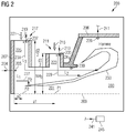
- Fig. 2 illustrates only an upper half of the sectional view of the entire burner 200.
- the burner 200 according to an embodiment of the present invention illustrated in Fig. 2 in a schematic sectional view comprises a chamber for combusting a fuel mixture, wherein the chamber is formed by a prechamber 201 and a combustion chamber 203.
- the burner 200 further comprises a first injector 205 for injecting a first fuel 204 into the prechamber 201 and main combustion chamber 203.
- the first fuel 204 may for example comprise hydrogen.
- the injector 205 is arranged at a front face 207 of the prechamber 201.
- Reference sign 209 indicates a central axis of the burner 200.
- the injector 205 injects the first fuel 204 into the prechamber 201 and from there into the combustion chamber 203.
- the burner 200 further comprises a swirler 211 for introducing a mixture of a second fuel 213 and air 215 into the prechamber 201, main combustion chamber 203.
- the burner further comprises a upstream swirler 217 for introducing a mixture of a third fuel 219 and further air 221 into the prechamber 201, main combustion chamber 203.
- the swirler 211 has an inner space 223 in which the second fuel 213 is at least partially mixed with the air 215.
- the swirler 211 comprises swirler vanes which are not illustrated in detail but partially illustrated in Fig. 4 .
- the upstream swirler 217 comprises also an inner space 225 in which the third fuel 219 is at least partially mixed with the further air 221.
- the inner space 225 of the upstream swirler is larger than the inner space 223 of the downstream swirler, in particular in the case, where a larger mass flow of the third fuel 219 is introduced into the upstream swirler than the mass flow of the second fuel 213 which is introduced in the downstream swirler 211.
- the sizes of the inner spaces 225, 223 of the upstream swirler and the downstream swirler, respectively, may be selected based on the combustion properties of the third fuel 219 and the second fuel 213.
- the position P1 (for example central position) of the downstream swirler 211 is spaced apart in the axial direction (parallel to the central axis 209) from the front face 207 by an amount a1.
- the position P2 of the upstream swirler 217 is spaced apart from the front face or front wall 207 of the burner 200 by an amount a2 which is smaller than the amount a1.
- the position P1 is thus spaced apart from the position P2 by a1-a2.
- a first flow path 227 of the first fuel 204 is indicated having a first premixing length L1.
- a second flow path 229 of the second fuel 213 is indicated which has a second premixing length L2.
- a third flow path 231 of the third fuel 219 mixed or partially mixed with the air 221 is indicated having a third premixing length L3.
- a flame is generated during the operation of the burner 200.
- the different fuel air mixtures generated by the first fuel 204 injected via the injector 205, by the second fuel 213 introduced via the downstream swirler 211 and the third fuel 219 introduced partially mixed with air using the upstream swirler 217 contribute at different regions of the flame 233.
- the downstream swirler 211 For injecting the second fuel 213, the downstream swirler 211 comprises second injectors 235 which are arranged at not illustrated swirler vanes.
- the upstream swirler 217 For injecting the third fuel 219, the upstream swirler 217 comprises third injectors 237 which may be arranged at not illustrated swirler vanes.
- the third fuel 219 by introducing the third fuel 219 via the upstream swirler 217 and mixing the third fuel 219 at least partially with the upstream portion of air 221, the third fuel 219 partially mixed with the air 221 enters the prechamber 201 radially inwards.
- the burner 200 (optionally) further comprises at least one temperature sensor 239 to measure a temperature in at least one region of the inside of the burner 200.
- the temperature sensor 239 generates a measurement signal 241 which is supplied to a controller 245 which is also comprised in the burner 200.
- the controller 245 receives the measurement signal 241, in particular from different regions within the burner 200 and adjusts the mass flows of the first fuel 204, the second fuel 213 and/or the third fuel 219.
- the mass flow of the air is controlled with the engine shaft speed 22 across the load range and by selecting the area of the swirlers in particular the air 215 and the further air 221.
- the controller 245 receives the measurement signal 241, and adjust the fuel in order to control the combustion process based on the measured temperature or measured temperatures in different regions of the combustion chamber and/or the prechamber 201, main combustion chamber 203.
- the combustion chamber 203 is limited by a combustion chamber wall 206.
- Fig. 3 schematically illustrates a burner 300 according to an embodiment of the present invention which may for example be incorporated into the gas turbine illustrated in Fig. 1 as the burner 100.
- Fig. 3 shows a burner 300 which has a number of similarities to the burner 200 illustrated in Fig. 2 .
- fuel galleries 351 are indicated which allow supply of the first fuel 304 via the first injectors 305 into the prechamber 301 and from there into the combustion chamber 303. Further, the fuel galleries 351 allow the introduction of the second fuel 313 via the downstream swirler 311 into the prechamber 301 and from there into the combustion chamber 303. Further, the fuel galleries 351 allow the introduction of the third fuel 319 via the upstream swirler 317 into the prechamber 301 and from there into the combustion chamber 303.
- the flow field of the introduced fuels partially mixed with air is also indicated as a forward flow field 353, a backward flow field 355 and a further backward flow field 357.
- the flame may stabilize between the forward flow field 353 and the backward flow field 355.
- the flow field 355 may also be referred to as central recirculation zone and the flow field 357 may also referred to as outer recirculation zone.
- the region close to the first injectors 305 may also be called pilot zone.
- the burner 300 further comprises an outer casing 359 which is not explicitly illustrated in the burner 200 illustrated in Fig. 2 .
- the first injectors are installed in a pilot body 361.
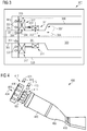
- Fig. 4 illustrates in a perspective view a burner 400 according to an embodiment of the present invention which may be used in the gas turbine illustrated in Fig. 1 .
- the burner 400 comprises a first injector 405 for injecting a first fuel 404. Further, the burner 400 comprises a downstream swirler 411 for introducing a mixture of a second fuel 413 and air into a prechamber 401. Further, the burner 400 comprises a upstream swirler 417 for introducing a third fuel 419 into the prechamber, mixed with air.
- the combustion chamber is limited by a combustion chamber wall 406.
- a transition duct 408 Downstream the combustion chamber, a transition duct 408 is arranged which guides the hot combustion gas via nozzle guide vanes 410 towards a turbine section of a gas turbine, such as turbine section 18 of the gas turbine illustrated in Fig. 1 .
- the swirlers comprise swirler vanes 416
- the proposed invention provides a design of a combustion system capable of burning synthetic fuels where the synthetic fuel is a mix of at least two or more components that have differing combustion properties.
- the fuels are injected at differing positions (principally defined by the flow-stream length to the reaction zone (e.g. flame)), where those positions are selected based on the combustion properties of the fuel component (diffusivity, flame speed, calorific value, ignition, etc).
- Dedicated swirlers are provided so that improved mixing and its control is achieved if simultaneous operation of fuels is required.
- the fuel injection system is designed to ensure that fuel is introduced as a function of its combustion property.
- the most reactive fuel (higher calorific value, i.e. the first fuel) is injected at a nominal distance from the flame location, L1, principally defined by the flow-stream length to the reaction zone, see figure 2 .
- L1 the flame location
- the distance is designed to ensure that the fuel is delivered quickly to the flame 233, however is not injected immediately onto the flame front, thus premixing with air prior to burning.
- the main purpose of this fuel stream is to promote flame stability. It is estimated that for normal full load operation up to 20 % of fuel is introduced in this manner. However up to 100% of fuel can be injected during startup or part load operation. Injection holes are designed for base load.
- a typical L1 may be estimated to be in the range of 20 mm to 150 mm with most devices operating in the region of 50 mm.
- a typical L2 may be in the range of 40 mm to 300 mm with most devices operating in the region of 100 mm.
- a typical L3 may be in the range of 60 mm to 400 mm with most devises operating in the region of 150 mm.
- the external diameter of the NH 3 swirler i.e. the upstream swirler 217, 317, 417) could be between 150 mm and 450 mm (typically around 250 mm), whilst the external diameter of the CH 4 swirler (i.e. the downstream swirler 211, 311, 411) could be between 50 and 250 mm (typically 100 mm).
- the effective area of both swirlers may be balanced to achieve an air mass flow for a required flame temperature. Different heights of the injection holes may be used to ensure better mixing within the swirler vanes.
- the main advantage of the described system may be the best premixing of each fuel stream with air and thus resulting in a single desirable flame location when burning synthetic fuels, i.e. stable, correct flame location, tolerant to load or fuel changeovers.
- An intelligent control method of fuel injection such as described in WO2007/082608 may be used to ensure the most optimal fuel ratio between the fuel streams.
- the control method would rely on inputs such as metal temperatures and differing frequency bands of combustion dynamics.
- the invention step provides a novel burner configuration with a fuel injection system capable of burning synthetic fuels.
- the proposed method is based on physical properties of these fuels such as diffusivity and flame speed to ensure an optimal flame location.
- the advantage lays in the improved and more rapid response in the fuel delivery to the flame to avoid flameout during part load, thus increasing the engine reliability.
- Low NOx due to premixing of fuel streams and a more uniform flame temperature across the combustion system may be achieved.
- Increased reliability of the combustion system when operated on synthetic fuels due to proximity of the most reactive fuel stream closer to the flame and the use of the intelligent control of the fuel streams may be achieved.
Landscapes
- Engineering & Computer Science (AREA)
- Chemical & Material Sciences (AREA)
- Combustion & Propulsion (AREA)
- Mechanical Engineering (AREA)
- General Engineering & Computer Science (AREA)
Abstract
It is described a burner (100, 200, 300, 400) for a gas turbine (10), comprising: a chamber (201, 203) for combusting a fuel mixture; a first injector (205) for injecting a first fuel (204) into the chamber; a downstream swirler (211) for introducing a mixture of a second fuel (213, CH4) and air into the chamber; and a upstream swirler (217) for introducing a mixture of a third fuel (219, NH3) different from the second fuel and further air into the chamber.
Description
- The present invention relates to a burner for a gas turbine, to a gas turbine and to a method for operating a burner of a gas turbine.
- Gas turbines are commonly used in industrial applications. To achieve the goal of an environmental friendly operation of the gas turbine, the gas turbine may be operated in a DLE (dry low emission) combustion mode, wherein the gas turbine produces low emissions, especially low NOx emissions. To achieve this goal, a good and uniform mixing of air and fuel in a burner of the gas turbine has to be achieved.
- Generally, combustion hardware for gas turbine (GT) engines is designed for a specific fuel (i.e. natural gas, diesel, syngas, landfill gas and other hydrocarbon fuels with varying Wobbe Index). However, for a hardware that was originally designed for one fuel and later when operated on a different fuel, the optimal operation will often be missed resulting in flashback (flame burning on the combustor surface), flameout (engine shutdown), combustion dynamics (hardware integrity), high pressure drop (performance loss) or high emissions.
- Low NOx-emission combustors utilize reduced peak flame temperatures within the combustor to limit the formation of thermal NOx through staging strategies such as lean premixed combustion. As combustion temperatures are decreased in low NOx applications, several other undesirable combustion phenomena become more prevalent and must be addressed. The low-NOx limit is often bounded by the onset of combustion instability in the form of Lean Blow Out (LBO) also known as flameout. Lean Blow Out occurs when the thermal energy generated by the burning fuel/air mixture is no longer sufficient to heat the incoming fuel-air mixture to the ignition point.
- Several conventional approaches run the engine close to the Lean Blow Off limit. Generally, the fuel will be introduced in multiple fuel injection holes and with differing staging across the load range. A pilot/primary fuel injection is used to control and stabilize locally the flame, thus avoiding the LBO. Fuel schedule map or intelligent control of the fuel splits such as in
WO2007/082608 are generally used to determine the running path of the engine across the load range. However, these methods do not allow in all situations to reliably operate the gas turbine, in order to achieve high efficiency and low emissions. - Thus, there may be a need for a burner for a gas turbine and for a method for operating a burner of a gas turbine, that allow an efficient combustion and at the same time having low emissions.
- This need may be met by the subject matter according to the independent claims. Advantageous embodiments of the present invention are described by the dependent claims.
- According to an embodiment of the present invention, it is provided a burner for a gas turbine, comprising a chamber for combusting a fuel mixture, a first injector for injecting a first fuel (in particular H2) into the chamber, an downstream swirler for introducing a mixture of a second fuel (in particular CH4) and air into the chamber, and a upstream swirler for introducing a mixture of a third fuel (in particular NH3) different from the second fuel and further air into the chamber.
- The burner may be adapted to simultaneously burn the first fuel, the second fuel and the third fuel. The downstream swirler and the upstream swirler may be of a similar configuration/geometry but may have different dimensions. In particular, the upstream swirler may have a larger size than the downstream swirler. In particular, the upstream swirler may introduce a larger amount (e.g. per time) of the third fuel into the chamber than the downstream swirler introduces an amount (e.g. per time) of the second fuel into the chamber. The second fuel and the third fuel are different and may have different combustion properties and also different thermo-chemical properties, such as diffusivity, calorific value, ignition temperature, flame speed. Depending on the combustion property of the second fuel and/or the third fuel, the configurations (in particular relative configuration or dimensions) of the downstream and the upstream swirler may be selected. Further, the relative positioning of the downstream swirler and the upstream swirler in the burner may depend on the different combustion properties of the different fuels and may also depend on the relative amounts of the second fuel and the third fuel being introduced into the chamber during the operation of the burner.
- The burner may achieve a reliable combustion of the three different fuels and may also achieve relatively low NOx emissions. A controller may control the operation of the burner, wherein the controller in particular may adjust the mass flows of the first fuel, the second fuel and the third fuel and may also control the amount of air introduced via the downstream swirler and/or via the upstream swirler.
- According to an embodiment of the present invention, a volume flow rate of the upstream swirler and/or a position of the upstream swirler relative to the downstream swirler is selected based on a combustion property of the third fuel, in particular relative to a combustion property of the second fuel, and/or based on a mass flow of the third fuel into the combustion chamber, in particular relative to a mass flow of the second fuel into the combustion chamber, wherein the volume flow rate of the upstream swirler is in particular between 2 and 5 times the volume flow rate of the downstream swirler.
- Thereby, an efficient combustion of the different fuels may be achieved. The combustion property of the fuel may include for example diffusivity, calorific value, ignition temperature, flame speed among others. Taking into account the combustion properties of the second fuel and the third fuel may allow to optimally design the geometry and/or size of the downstream and upstream swirler.
- In general, the downstream swirler and/or the upstream swirler may have a design of a so-called radial swirler which introduces air and the respective fuel using swirler vanes which guide the air into an inside of the respective swirler, wherein one or more injectors for the respective fuel are provided at the swirler vanes, in order to achieve a mixing of the air with the respective fuel. The downstream swirler and/or the upstream swirler may have substantially a cylindrical geometry and may at least partially surround the chamber of the burner, in particular a pre-chamber of the burner.
- According to an embodiment of the present invention, the burner is adapted to simultaneously burn a second fuel together with a third fuel, the third fuel mass flow rate being between 70% and 97% of a total mass flow rate burned, wherein a calorific value of the second fuel is in particular between 1.2 and 5 times a calorific value of the third fuel, which may in particular comprises ammonia (NH3According to an embodiment of the present invention, a position of the downstream swirler is, in an axial direction away from the first injector (pilot burner), spaced apart from a position of the upstream swirler, in particular between 0.5 and 2 times a diameter of a prechamber of the combustion chamber.
- The upstream swirler may thus be closer (in the axial direction) located at the first injector from pilot burner than the downstream swirler. Thereby, the third fuel introduced via the upstream swirler into the chamber of the burner may stream along a longer mixing path to reach a combustion region of the burner than the second fuel which is introduced via the downstream swirler. Thereby, a larger amount of the third fuel is efficiently supported and also a lower calorific value relative to the calorific value of the second fuel may be accounted for.
- According to an embodiment of the present invention, the first, the second and the third fuels flow rates, at least partially mixed with air, along flow paths having a first, second and third premixing length (L1, L2, L3), respectively from an injection location in the burner to a combustion region within the burner, wherein the burner is adapted such that the first premixing length is smaller than the second premixing length and the second premixing length is smaller than the third premixing length, wherein the first premixing length is in particular between 20 mm and 100 mm, wherein the second premixing length is in particular between 40 mm and 300 mm, wherein the third premixing length is in particular between 60 mm and 400 mm.
- The first fuel may have a highest calorific value, the second fuel may have a medium calorific value and the third fuel may have the lowest calorific value of all fuels used during operation of the burner.
- According to an embodiment of the present invention, the downstream swirler comprises second injectors and the upstream swirler comprises third injectors for supplying the second and third fuels respectively, into the swirlers, wherein a diameter (e.g. inner pitch circle diameter) of the upstream swirler is in particular between 150 mm and 450 mm, wherein inner pitch circle diameter of the downstream swirler is in particular between 50 mm and 250 mm.
- The diameters of the upstream swirler and the downstream swirler may be selected based on an amount of the respective fuel introduced via the respective swirler into the chamber of the burner and may also be selected based on the respective calorific value (and/or other combustion properties) of the fuel. The more the mass flow per time is introduced via the respective swirler into the chamber, the larger the diameter of the respective swirler may be selected. Thereby, an efficient premixing within the respective swirler of the respective fuel with the air may be achieved before introducing the premixed fuel/air into the chamber of the burner.
- The higher the calorific value of the fuel that is introduced by the respective swirler into the chamber of the burner the farther away (in the axial direction) from the first injectors the respective swirler may be located.
- According to an embodiment of the present invention, the swirler comprises plural swirler vanes, circumferentially spaced apart, for guiding air entering from radially outwards into the swirler radially inwards and partially in a circumferential direction, wherein the upstream swirler comprises plural further swirler vanes, circumferentially spaced apart, for guiding upstream air entering from radially outwards into the upstream swirler radially inwards and partially in a circumferential direction.
- The swirler vanes may comprise each a substantially flat or plane surface along which air introduced radially is guided towards inwards section of the swirler. The injectors may be formed as one, two or more holes within the surface of the swirler vane. Thereby, an efficient premixing of the fuel with the air may be achieved and the premixed air and fuel may be efficiently guided radially (and partially circumferentially) inwards into the swirler and from there into the chamber of the burner.
- According to an embodiment of the present invention, the second injectors are arranged on the swirler vanes such as to partially mix the second fuel with the guided air, wherein the third injectors are arranged on the upstream swirler vanes such as to partially mix the third fuel with the guided further air, wherein in particular two or more injectors in the swirlers are formed at each of the swirler vanes. The swirlers may in particular be configured as radial swirlers.
- According to an embodiment of the present invention, the chamber comprises a prechamber and a combustion chamber, having a larger radial extent than the prechamber, wherein the swirler and the further swirler enclose the prechamber such that the second fuel partially mixed with air enters the prechamber radially inwards and such that the third fuel partially mixed with air enters the prechamber radially inwards. Thereby, a simple efficient design is achieved.
- The first injectors may be arranged on a front face (of a wall) of the combustor. Thereby, the first fuel is enabled to be injected closer to a central axis (running in the axial direction) of the burner than the second fuel and the third fuel. The combustion chamber may have a cylindrical shape and the central axis may represent a cylinder axis of the combustion chamber. The first fuel may have a highest reactivity compared of the reactivities of the second fuel and the third fuel. Thus, the first fuel may be ignited fastest and may provide a flame close to the central axis and also close to the first injector. This initial flame may act to ignite the mixture of the second fuel and air and also to ignite the mixture of the third fuel and air further axially downstream away from the first injector, such that an extended flame region is formed. During operation of the burner, a pilot zone may be formed close to the first injector and close to the central axis of the burner. A central recirculation zone may be formed close to the central axis of the burner and axially spaced apart or extending from the region where the first injector or first injectors are arranged. Within the burner or in particular within the chamber of the burner, a forward flow (away from the front plate and streaming substantially in an axial direction) may be formed primarily by a mixture of the second fuel and air and a mixture of the third fuel and air in a region radially close to the downstream and upstream swirler but spaced apart from the central axis of the burner. A backflow may be formed in a region close to the central axis of the burner. The flame may form/establish in a region where the burning velocity of a fuel and air mixture is relatively close to the incoming flow speed so that equilibrium is formed or the difference (between burning velocity against the flow speed) is small or substantially zero. During a stable operation, the flame may extend in the axial direction and may be spaced apart from the central axis the more, the more the flame is axially spaced apart from the front plate or the first injectors.
- The three different fuels or fuel air mixtures may contribute in different regions of the flame to a different amount. For example, the first fuel mixed with air may contribute to the flame to a highest degree axially close to the front plate or close to the first injectors and also close to the central axis of the burner. The mixture of the second fuel with air may contribute most to the flame in a region farther spaced apart from the central axis (to a medium degree) and also spaced apart in the axial direction from the front plate in a medium degree. Further, the third fuel mixed with air may contribute to the flame in a region of the flame which is spaced by an even larger amount in the axial direction from the front plate and which is spaced also in the radial direction from the central axis more than the mixtures of the other fuels with the air. Other configurations are possible.
- According to an embodiment of the present invention, the burner further comprises at least one temperature sensor arranged to measure a temperature in at least one region of the inside of the burner and a controller adapted to adjust a mass flow of fuel and/or a mass flow of air into the downstream swirler and/or the upstream swirler and/or the first injector based on the measured temperature. The controller may allow to optimally adjust the mass flow of the fuels and the air to efficiently burn the fuels, while limiting the emissions.
- According to a further embodiment of the present invention it is provided a gas turbine which comprises the burner as described in the embodiments above and which further comprises a compressor stage and a turbine stage of a rotor having plural blade vanes connected to it. According to an embodiment it is provided a gas turbine, comprising a shaft having blade vanes connected to it and at least one burner according to one of the embodiments described above, arranged such that combustion gas expelled by the burner impacts on the blade vanes and thereby drives the shaft.
- It should be understood that features which have been disclosed, individually or in any combination, with respect to a burner for a gas turbine may also be applied to a method for operating a burner of a gas turbine according to an embodiment of the present invention and vice versa.
- According to an embodiment of the present invention, the air or at least a portion of the air required to burn the first fuel is provided via the upstream swirler and/or via the downstream swirler. In particular, the upstream swirler may provide the majority of air required to burn the first fuel. Advantageously for this is, when the upstream swirler is located axially close to the first injector or first injectors. A compromise may be found in order to optimize a premixing path length of a mixing path of the third fuel mixed or mixing with air and the requirement that sufficient air is supplied close to the first injector outlets, in order to ignite and burn the first fuel.
- In addition to conventional hydrocarbon fuels for gas turbines, a synthetic fuel such as ammonia (NH3) or hydrogen (H2) is used according to embodiments of the present invention to generate the required energy. Due to different thermo-chemical properties (such as diffusivity, calorific value, ignition temperatures, flame speed) of these synthetic fuels the combustion process becomes complex. For example, in conventional gas turbines the hydrogen-air combustion occurs at higher flame speeds and may result in flashback. The invention provides a solution for these disadvantages.
- In spite of the lower calorific value of ammonia (around 22.5 MJ/kg), ammonia-air combustion may be initiated efficiently in embodiments of the present invention. Reliable combustion in gas turbine engines may be achieved in embodiments of the present invention wherein a mixture of these synthetic fuels is used within the system.
- Embodiments of the present invention present an injection system capable to achieve reliable combustion of differing synthetic fuels (such as NH3 and H2) as well as acceptable NOx emissions. This is achieved if the combustion dynamics is reduced and/or ensuring a better mixing of the pilot fuel stream.
- A further improvement on the control and functionality of the method is described with the emphasis on the fuel split controller.
- Hence this invention disclosure proposes the DLE combustion system for efficient burning of ammonia (on its own) and also the combination of ammonia and Hydrogen enriched with hydrocarbon fuels such as methane and propane.
- Embodiments of the invention improve the capability of the combustion system of a gas turbine to burn primarily synthetic fuels such as NH3 or H2.
- It has to be noted that embodiments of the invention have been described with reference to different subject matters. In particular, some embodiments have been described with reference to method type claims whereas other embodiments have been described with reference to apparatus type claims. However, a person skilled in the art will gather from the above and the following description that, unless other notified, in addition to any combination of features belonging to one type of subject matter also any combination between features relating to different subject matters, in particular between features of the method type claims and features of the apparatus type claims is considered as to be disclosed with this document.
- The aspects defined above and further aspects of the present invention are apparent from the examples of embodiment to be described hereinafter and are explained with reference to the examples of embodiment. The invention will be described in more detail hereinafter with reference to examples of embodiment but to which the invention is not limited.
- Embodiments of the present invention are now described with reference to the accompanying drawings. The invention is not restricted to the described or illustrated embodiments.
-
Fig. 1 schematically illustrates in a sectional view a gas turbine according to an embodiment of the present invention including a burner according to an embodiment of the present invention; -
Fig. 2 illustrates in a schematic sectional view a burner according to an embodiment of the present invention which may for example be used within the gas turbine illustrated inFig. 1 ; -
Fig. 3 schematically illustrates in a sectional view a burner according to an embodiment of the present invention which may for example be used in the gas turbine illustrated inFig. 1 ; and -
Fig. 4 illustrates in a perspective view a burner according to an embodiment of the present invention which may for example be used in the gas turbine illustrated inFig. 1 . - The illustration in the drawings is in schematic form.
-
FIG. 1 shows an example of agas turbine engine 10 in a sectional view. Thegas turbine engine 10 comprises, in flow series, aninlet 12, acompressor section 14, acombustor section 16 and aturbine section 18 which are generally arranged in flow series and generally about and in the direction of a longitudinal orrotational axis 20. Thegas turbine engine 10 further comprises ashaft 22 which is rotatable about therotational axis 20 and which extends longitudinally through thegas turbine engine 10. Theshaft 22 drivingly connects theturbine section 18 to thecompressor section 14. - In operation of the
gas turbine engine 10,air 24, which is taken in through theair inlet 12 is compressed by thecompressor section 14 and delivered to the combustion section orburner section 16. Theburner section 16 comprises aburner plenum 26, one ormore combustion chambers 28 and at least oneburner 30 fixed to eachcombustion chamber 28. Thecombustion chambers 28 and theburner injection portions 30 are located inside theburner plenum 26. The compressed air passing through thecompressor 14 enters adiffuser 32 and is discharged from thediffuser 32 into theburner plenum 26 from where a portion of the air enters theburner injection portion 30 and is mixed with a gaseous or liquid fuel. The air/fuel mixture is then burned and thecombustion gas 34 or working gas from the combustion is channelled through thecombustion chamber 28 to theturbine section 18 via atransition duct 17.
This exemplarygas turbine engine 10 has a cannularcombustor section arrangement 16, which is constituted by an annular array ofcombustor cans 19 each having theburner injection portion 30 and thecombustion chamber 28, thetransition duct 17 has a generally circular inlet that interfaces with thecombustor chamber 28 and an outlet in the form of an annular segment. An annular array of transition duct outlets form an annulus for channelling the combustion gases to theturbine 18. - The
turbine section 18 comprises a number ofblade carrying discs 36 attached to theshaft 22. In the present example, twodiscs 36 each carry an annular array ofturbine blades 38. However, the number of blade carrying discs could be different, i.e. only one disc or more than two discs. In addition, guidingvanes 40, which are fixed to astator 42 of thegas turbine engine 10, are disposed between the stages of annular arrays ofturbine blades 38. Between the exit of thecombustion chamber 28 and the leadingturbine blades 38inlet guiding vanes 44 are provided and turn the flow of working gas onto theturbine blades 38. - The combustion gas from the
combustion chamber 28 enters theturbine section 18 and drives theturbine blades 38 which in turn rotate theshaft 22. The guidingvanes turbine blades 38. - The
turbine section 18 drives thecompressor section 14. Thecompressor section 14 comprises an axial series of vane stages 46 and rotor blade stages 48. The rotor blade stages 48 comprise a rotor disc supporting an annular array of blades. Thecompressor section 14 also comprises acasing 50 that surrounds the rotor stages and supports the vane stages 48. The guide vane stages include an annular array of radially extending vanes that are mounted to thecasing 50. The vanes are provided to present gas flow at an optimal angle for the blades at a given engine operational point. Some of the guide vane stages have variable vanes, where the angle of the vanes, about their own longitudinal axis, can be adjusted for angle according to air flow characteristics that can occur at different engine operations conditions. - The
casing 50 defines a radiallyouter surface 52 of thepassage 56 of thecompressor 14. A radiallyinner surface 54 of thepassage 56 is at least partly defined by arotor drum 53 of the rotor which is partly defined by the annular array ofblades 48. - The present invention is described with reference to the above exemplary turbine engine having a single shaft or spool connecting a single, multi-stage compressor and a single, one or more stage turbine. However, it should be appreciated that the present invention is equally applicable to two or three shaft engines and which can be used for industrial, aero or marine applications.
- The terms upstream and downstream refer to the flow direction of the airflow and/or working gas flow through the engine unless otherwise stated. The terms forward and rearward refer to the general flow of gas through the engine. The terms axial, radial and circumferential are made with reference to the
rotational axis 20 of the engine. - The
gas turbine 10 illustrated inFig. 1 comprises aburner 100 according to an embodiment of the present invention. Theburner 100 may be configured in a similar manner as the burners illustrated inFigs. 2 ,3 or 4 . Theburner injection portion 30 may comprise fuel injectors, swirlers and a prechamber, as detailed below. -
Fig. 2 illustrates only an upper half of the sectional view of theentire burner 200. Theburner 200 according to an embodiment of the present invention illustrated inFig. 2 in a schematic sectional view comprises a chamber for combusting a fuel mixture, wherein the chamber is formed by aprechamber 201 and acombustion chamber 203. Theburner 200 further comprises afirst injector 205 for injecting afirst fuel 204 into theprechamber 201 andmain combustion chamber 203. Thefirst fuel 204 may for example comprise hydrogen. Theinjector 205 is arranged at afront face 207 of theprechamber 201.Reference sign 209 indicates a central axis of theburner 200. Theinjector 205 injects thefirst fuel 204 into theprechamber 201 and from there into thecombustion chamber 203. - The
burner 200 further comprises aswirler 211 for introducing a mixture of asecond fuel 213 andair 215 into theprechamber 201,main combustion chamber 203. The burner further comprises aupstream swirler 217 for introducing a mixture of athird fuel 219 andfurther air 221 into theprechamber 201,main combustion chamber 203. Theswirler 211 has aninner space 223 in which thesecond fuel 213 is at least partially mixed with theair 215. To achieve this, theswirler 211 comprises swirler vanes which are not illustrated in detail but partially illustrated inFig. 4 . - The
upstream swirler 217 comprises also aninner space 225 in which thethird fuel 219 is at least partially mixed with thefurther air 221. Theinner space 225 of the upstream swirler is larger than theinner space 223 of the downstream swirler, in particular in the case, where a larger mass flow of thethird fuel 219 is introduced into the upstream swirler than the mass flow of thesecond fuel 213 which is introduced in thedownstream swirler 211. The sizes of theinner spaces third fuel 219 and thesecond fuel 213. - The position P1 (for example central position) of the
downstream swirler 211 is spaced apart in the axial direction (parallel to the central axis 209) from thefront face 207 by an amount a1. The position P2 of theupstream swirler 217 is spaced apart from the front face orfront wall 207 of theburner 200 by an amount a2 which is smaller than the amount a1. The position P1 is thus spaced apart from the position P2 by a1-a2. - In
Fig. 2 , afirst flow path 227 of thefirst fuel 204 is indicated having a first premixing length L1. Further, asecond flow path 229 of thesecond fuel 213 is indicated which has a second premixing length L2. Further, athird flow path 231 of thethird fuel 219 mixed or partially mixed with theair 221 is indicated having a third premixing length L3. As is evident fromFig. 2 , L1 < L2 < L3. - In the
region 233, a flame is generated during the operation of theburner 200. As can be taken fromFig. 2 , the different fuel air mixtures generated by thefirst fuel 204 injected via theinjector 205, by thesecond fuel 213 introduced via thedownstream swirler 211 and thethird fuel 219 introduced partially mixed with air using theupstream swirler 217 contribute at different regions of theflame 233. - For injecting the
second fuel 213, thedownstream swirler 211 comprisessecond injectors 235 which are arranged at not illustrated swirler vanes. For injecting thethird fuel 219, theupstream swirler 217 comprisesthird injectors 237 which may be arranged at not illustrated swirler vanes. By introducing thesecond fuel 213 via thedownstream swirler 211 and partially mixing thesecond fuel 213 with theair 215, thesecond fuel 213 partially mixed with theair 215 enters theprechamber 201 radially inwards. - Similarly, by introducing the
third fuel 219 via theupstream swirler 217 and mixing thethird fuel 219 at least partially with the upstream portion ofair 221, thethird fuel 219 partially mixed with theair 221 enters theprechamber 201 radially inwards. - The burner 200 (optionally) further comprises at least one
temperature sensor 239 to measure a temperature in at least one region of the inside of theburner 200. Thetemperature sensor 239 generates ameasurement signal 241 which is supplied to acontroller 245 which is also comprised in theburner 200. Thecontroller 245 receives themeasurement signal 241, in particular from different regions within theburner 200 and adjusts the mass flows of thefirst fuel 204, thesecond fuel 213 and/or thethird fuel 219. The mass flow of the air is controlled with theengine shaft speed 22 across the load range and by selecting the area of the swirlers in particular theair 215 and thefurther air 221. Thecontroller 245 receives themeasurement signal 241, and adjust the fuel in order to control the combustion process based on the measured temperature or measured temperatures in different regions of the combustion chamber and/or theprechamber 201,main combustion chamber 203. Thecombustion chamber 203 is limited by acombustion chamber wall 206. -
Fig. 3 schematically illustrates aburner 300 according to an embodiment of the present invention which may for example be incorporated into the gas turbine illustrated inFig. 1 as theburner 100. - Elements and structures similar in structure and/or function are labelled in
Figs. 2 ,3 and 4 by reference signs that differ only in the first digit. -
Fig. 3 shows aburner 300 which has a number of similarities to theburner 200 illustrated inFig. 2 . InFig. 3 ,fuel galleries 351 are indicated which allow supply of thefirst fuel 304 via thefirst injectors 305 into theprechamber 301 and from there into thecombustion chamber 303. Further, thefuel galleries 351 allow the introduction of thesecond fuel 313 via thedownstream swirler 311 into theprechamber 301 and from there into thecombustion chamber 303. Further, thefuel galleries 351 allow the introduction of thethird fuel 319 via theupstream swirler 317 into theprechamber 301 and from there into thecombustion chamber 303. - In
Fig. 3 , the flow field of the introduced fuels partially mixed with air is also indicated as aforward flow field 353, abackward flow field 355 and a furtherbackward flow field 357. The flame may stabilize between theforward flow field 353 and thebackward flow field 355. Theflow field 355 may also be referred to as central recirculation zone and theflow field 357 may also referred to as outer recirculation zone. The region close to thefirst injectors 305 may also be called pilot zone. - The
burner 300 further comprises anouter casing 359 which is not explicitly illustrated in theburner 200 illustrated inFig. 2 . The first injectors are installed in apilot body 361. -
Fig. 4 illustrates in a perspective view aburner 400 according to an embodiment of the present invention which may be used in the gas turbine illustrated inFig. 1 . Theburner 400 comprises afirst injector 405 for injecting afirst fuel 404. Further, theburner 400 comprises adownstream swirler 411 for introducing a mixture of asecond fuel 413 and air into aprechamber 401. Further, theburner 400 comprises aupstream swirler 417 for introducing athird fuel 419 into the prechamber, mixed with air. The combustion chamber is limited by acombustion chamber wall 406. Downstream the combustion chamber, atransition duct 408 is arranged which guides the hot combustion gas vianozzle guide vanes 410 towards a turbine section of a gas turbine, such asturbine section 18 of the gas turbine illustrated inFig. 1 . The swirlers compriseswirler vanes 416 - The proposed invention provides a design of a combustion system capable of burning synthetic fuels where the synthetic fuel is a mix of at least two or more components that have differing combustion properties. The fuels are injected at differing positions (principally defined by the flow-stream length to the reaction zone (e.g. flame)), where those positions are selected based on the combustion properties of the fuel component (diffusivity, flame speed, calorific value, ignition, etc). Dedicated swirlers are provided so that improved mixing and its control is achieved if simultaneous operation of fuels is required.
- The fuel injection system is designed to ensure that fuel is introduced as a function of its combustion property. The most reactive fuel (higher calorific value, i.e. the first fuel) is injected at a nominal distance from the flame location, L1, principally defined by the flow-stream length to the reaction zone, see
figure 2 . The distance is designed to ensure that the fuel is delivered quickly to theflame 233, however is not injected immediately onto the flame front, thus premixing with air prior to burning. The main purpose of this fuel stream is to promote flame stability. It is estimated that for normal full load operation up to 20 % of fuel is introduced in this manner. However up to 100% of fuel can be injected during startup or part load operation. Injection holes are designed for base load. A typical L1 may be estimated to be in the range of 20 mm to 150 mm with most devices operating in the region of 50 mm. - At a distance L2, it is proposed to inject fuel with medium reactivity/calorific value (i.e. the second fuel), such as natural gas, whilst at L3, the (third fuel) NH3 is being injected as it requires much longer mixing length due to low diffusivity into air. The main purpose of the natural gas stream is to provide back-up functionality as well as aiding the ignition process or part load operation in case that the H2 stream is not available. The NH3 stream however is injected furthest upstream the flame front to ensure that the fuel and air is well premixed prior to reaching the
flame 233. Most of the power output will be produced as result of the NH3 burning and majority of operation would be at base load. It is expected that up to 95% of NH3 could be used at base load. A typical L2 may be in the range of 40 mm to 300 mm with most devices operating in the region of 100 mm. A typical L3 may be in the range of 60 mm to 400 mm with most devises operating in the region of 150 mm. - It should be noted that the external diameter of the NH3 swirler (i.e. the
upstream swirler downstream swirler - The main advantage of the described system may be the best premixing of each fuel stream with air and thus resulting in a single desirable flame location when burning synthetic fuels, i.e. stable, correct flame location, tolerant to load or fuel changeovers.
- An intelligent control method of fuel injection such as described in
WO2007/082608 may be used to ensure the most optimal fuel ratio between the fuel streams. The control method would rely on inputs such as metal temperatures and differing frequency bands of combustion dynamics. - The invention step provides a novel burner configuration with a fuel injection system capable of burning synthetic fuels. The proposed method is based on physical properties of these fuels such as diffusivity and flame speed to ensure an optimal flame location. The advantage lays in the improved and more rapid response in the fuel delivery to the flame to avoid flameout during part load, thus increasing the engine reliability. Low NOx due to premixing of fuel streams and a more uniform flame temperature across the combustion system may be achieved. Increased reliability of the combustion system when operated on synthetic fuels due to proximity of the most reactive fuel stream closer to the flame and the use of the intelligent control of the fuel streams may be achieved.
- It should be noted that the term "comprising" does not exclude other elements or steps and "a" or "an" does not exclude a plurality. Also elements described in association with different embodiments may be combined. It should also be noted that reference signs in the claims should not be construed as limiting the scope of the claims.
-
- 10
- gas turbine
- 12
- inlet
- 14
- compressor section
- 16
- combustor section
- 17
- transition duct
- 18
- turbine section
- 19
- combustor can
- 20
- rotational axis
- 22
- shaft
- 24
- air
- 26
- burner plenum
- 28
- combustion chamber
- 30
- burner injection portion
- 32
- diffuser
- 34
- combustion gas
- 36
- blade disk
- 38
- turbine blades
- 40
- guide vanes
- 42
- stator
- 44
- guide vanes
- 46
- vane stage
- 48
- rotor blade stage
- 50
- casing
- 52
- radially outer surface
- 54
- radially inner surface
- 56
- passage
- 100
- burner
- 200
- burner
- 201
- prechamber
- 203
- main combustion chamber
- 204
- first fuel
- 205
- first injector
- 206
- combustion chamber wall
- 207
- front face or front wall or pilot face
- 209
- central axis
- 211
- downstream swirler
- 213
- second fuel
- 215
- air
- 217
- upstream swirler
- 219
- third fuel
- 221
- upstream portion of air
- 223
- inner space of the swirler
- 225
- inner space of the further swirler
- 227
- first flow path
- 229
- second flow path
- 231
- third flow path
- 233
- flame region
- 235
- second injectors
- 237
- third injectors
- 239
- temperature sensors
- 241
- measurement signal
- 245
- controller
- P1
- position of the swirler
- P2
- position of the further swirler
- a1, a2
- coordinates of the positions in the axial direction
- 351
- fuel galleries
- 353
- forward flow
- 355
- backward flow
- 357
- other backward flow
- 359
- outer casing
- 408
- transition duct
- 410
- nozzle guide vanes
- 416
- swirler vanes
Claims (15)
- Burner (100, 200, 300, 400) for a gas turbine (10), comprising:a chamber (201, 203) for combusting a fuel mixture;a first injector (205) for injecting a first fuel (204) into the chamber;a downstream swirler (211) for introducing a mixture of a second fuel (213, CH4) and air into the chamber; andan upstream swirler (217) for introducing a mixture of a third fuel (219, NH3) different from the second fuel and further air into the chamber.
- Burner according to claim 1, wherein a volume of an inner space (225) of the upstream swirler (217) and/or a position (P1) of the further swirler relative to the swirler (213) is selected based on a combustion property of the third fuel (219), in particular relative to a combustion property of the second fuel (213), and/or based on a mass flow of the third fuel into the chamber (201, 203), in particular relative to a mass flow of the second fuel into the chamber,
wherein the volume of an inner space (225) of the further swirler (217) is in particular between 2 and 5 times the volume of an inner space (223) of the downstream swirler (211). - Burner according to one of claims 1 or 2, wherein the burner is adapted to simultaneously burn a second mass per time of the second fuel (CH4) together with a third mass per time of the third fuel (NH3), the third mass per time being between 70% and 97% of a total mass per time burned, wherein a calorific value of the second fuel is in particular between 1.2 and 5 times a calorific value of the third fuel.
- Burner according to one of the preceding claims, wherein a position (P1) of the downstream swirler (211) is, in an axial direction (209) away from the first injector (205), spaced apart from a position (P2) of the further swirler (217), in particular between 0.5 and 2 times a diameter of a prechamber comprised in the combustion chamber.
- Burner according to one of the preceding claims, wherein the first, the second and the third fuels flow, as a mixture with air, along flow paths (227, 229, 231) having a first, second and third premixing length (L1, L2, L3), respectively from a respective injection location into the burner to a combustion region (233) within the burner,
wherein the burner is adapted such that
the first premixing length (L1) is smaller than the second premixing length (L2) and
the second premixing length (L2) is smaller than the third premixing length (L3),
wherein the first premixing length is in particular between 20 mm and 150 mm,
wherein the second premixing length is in particular between 40 mm and 300 mm,
wherein the third premixing length is in particular between 60 mm and 400 mm. - Burner according to one of the preceding claims, wherein the downstream swirler (211) comprises second injectors (235) and the upstream swirler (217) comprises third injectors (237) for supplying the second and third fuels, respectively, into the swirlers,
wherein a diameter (d2) of the upstream swirler (217) is in particular between 150 mm and 450 mm,
wherein a diameter (d1) of the swirler (211) is in particular between 50 mm and 250 mm. - Burner according to one of the preceding claims, wherein the downstream swirler (211) comprises plural swirler vanes (416), circumferentially spaced apart, for guiding air (415) entered from radially outwards into the swirler radially inwards and partially in a circumferential direction, wherein the further swirler (417) comprises plural further swirler vanes (416), circumferentially spaced apart, for guiding further air (421) entered from radially outwards into the further swirler radially inwards and partially in a circumferential direction.
- Burner according to the preceding claim, wherein the second injectors (235) are arranged on the swirler vanes (416) such as to partially mix the second fuel (215) with the guided air, wherein the third injectors (237) are arranged on the upstream swirler vanes (417) such as to partially mix the third fuel (219) with the guided further air,
wherein in particular two or more injectors in the swirlers are formed at each of the swirler vanes. - Burner according to one of the preceding claims, wherein the chamber comprises a prechamber (201) and a combustion chamber (203), having a larger radial extent than the prechamber,
wherein the downstream swirler (211) and the upstream swirler (217) enclose the prechamber (201)such that the second fuel (213) partially mixed with air enters the prechamber (201) radially inwards andsuch that the third fuel (219) partially mixed with air enters the prechamber (201) radially inwards. - Burner according to the preceding claim, wherein the first injectors (205) are arranged on a front face (207) of the prechamber (201).
- Burner according to one of the preceding claims, further comprising:at least one temperature sensor (239) arranged to measure a temperature in at least one region of the inside of the burner; anda controller (245) adapted to adjust a mass flow of a respective fuel and/or a mass flow of air into the downstream swirler (211) and/or the upstream swirler (217) and/or the first injector (205) based on the measured temperature.
- Gas turbine (10), comprising:a shaft (22) having blade vanes (38) connected to it; andat least one burner (100, 200, 300, 400) according to one of the preceding claims, arranged such that combustion gas expelled by the burner impacts on the blade vanes (38) and thereby drives the shaft (22).
- Method for operating a burner (100, 200, 300, 400) of a gas turbine (10), the method comprising:injecting a first fuel (204) into a chamber (201, 203) using a first injector (205);mixing a second fuel (213, CH4) and air (215) using a swirler (211) and introducing the mixture into the chamber; andmixing a third fuel (219, NH3) different from the second fuel and further air (221) using a further swirler and introducing the further mixture into the chamber.
- Method according to the preceding claim, wherein air required to burn the first fuel (204) is provided via the upstream swirler (217) and/or the downstream swirler (211).
- Method according to one of the two preceding claims, wherein the first fuel (204) comprises or is hydrogen, the second fuel (213) comprises or is a hydrocarbon or a mixture of hydrocarbons, the third fuel (219) comprises or is ammonia.
Priority Applications (1)
| Application Number | Priority Date | Filing Date | Title |
|---|---|---|---|
| EP16160740.3A EP3220050A1 (en) | 2016-03-16 | 2016-03-16 | Burner for a gas turbine |
Applications Claiming Priority (1)
| Application Number | Priority Date | Filing Date | Title |
|---|---|---|---|
| EP16160740.3A EP3220050A1 (en) | 2016-03-16 | 2016-03-16 | Burner for a gas turbine |
Publications (1)
| Publication Number | Publication Date |
|---|---|
| EP3220050A1 true EP3220050A1 (en) | 2017-09-20 |
Family
ID=55542534
Family Applications (1)
| Application Number | Title | Priority Date | Filing Date |
|---|---|---|---|
| EP16160740.3A Withdrawn EP3220050A1 (en) | 2016-03-16 | 2016-03-16 | Burner for a gas turbine |
Country Status (1)
| Country | Link |
|---|---|
| EP (1) | EP3220050A1 (en) |
Cited By (5)
| Publication number | Priority date | Publication date | Assignee | Title |
|---|---|---|---|---|
| JP2020139699A (en) * | 2019-02-28 | 2020-09-03 | 株式会社Ihi | Combustor |
| WO2022079523A1 (en) * | 2020-10-14 | 2022-04-21 | King Abdullah University Of Science And Technology | Adjustable fuel injector for flame dynamics control |
| WO2022101608A1 (en) * | 2020-11-12 | 2022-05-19 | University College Cardiff Consultants Limited | Combustor systems and methods |
| US11920525B2 (en) | 2022-08-05 | 2024-03-05 | Rtx Corporation | Liquid and hydrogen/methane fuel injector |
| US11976820B2 (en) | 2022-08-05 | 2024-05-07 | Rtx Corporation | Multi-fueled, water injected hydrogen fuel injector |
Citations (7)
| Publication number | Priority date | Publication date | Assignee | Title |
|---|---|---|---|---|
| US5983642A (en) * | 1997-10-13 | 1999-11-16 | Siemens Westinghouse Power Corporation | Combustor with two stage primary fuel tube with concentric members and flow regulating |
| US6151899A (en) * | 1998-05-09 | 2000-11-28 | Alstom Gas Turbines Limited | Gas-turbine engine combustor |
| US20040238654A1 (en) * | 2003-01-22 | 2004-12-02 | Hagen David L. | Thermodynamic cycles using thermal diluent |
| WO2007082608A1 (en) | 2006-01-19 | 2007-07-26 | Siemens Aktiengesellschaft | Fuel ratio control in a combustion apparatus with multiple fuel supply lines |
| US20080083224A1 (en) * | 2006-10-05 | 2008-04-10 | Balachandar Varatharajan | Method and apparatus for reducing gas turbine engine emissions |
| US20100126176A1 (en) * | 2008-11-26 | 2010-05-27 | Ik Soo Kim | Dual swirler |
| EP2902708A1 (en) * | 2014-06-12 | 2015-08-05 | Kawasaki Jukogyo Kabushiki Kaisha | Multi-fuel-supporting gas-turbine combustor |
-
2016
- 2016-03-16 EP EP16160740.3A patent/EP3220050A1/en not_active Withdrawn
Patent Citations (7)
| Publication number | Priority date | Publication date | Assignee | Title |
|---|---|---|---|---|
| US5983642A (en) * | 1997-10-13 | 1999-11-16 | Siemens Westinghouse Power Corporation | Combustor with two stage primary fuel tube with concentric members and flow regulating |
| US6151899A (en) * | 1998-05-09 | 2000-11-28 | Alstom Gas Turbines Limited | Gas-turbine engine combustor |
| US20040238654A1 (en) * | 2003-01-22 | 2004-12-02 | Hagen David L. | Thermodynamic cycles using thermal diluent |
| WO2007082608A1 (en) | 2006-01-19 | 2007-07-26 | Siemens Aktiengesellschaft | Fuel ratio control in a combustion apparatus with multiple fuel supply lines |
| US20080083224A1 (en) * | 2006-10-05 | 2008-04-10 | Balachandar Varatharajan | Method and apparatus for reducing gas turbine engine emissions |
| US20100126176A1 (en) * | 2008-11-26 | 2010-05-27 | Ik Soo Kim | Dual swirler |
| EP2902708A1 (en) * | 2014-06-12 | 2015-08-05 | Kawasaki Jukogyo Kabushiki Kaisha | Multi-fuel-supporting gas-turbine combustor |
Cited By (8)
| Publication number | Priority date | Publication date | Assignee | Title |
|---|---|---|---|---|
| JP2020139699A (en) * | 2019-02-28 | 2020-09-03 | 株式会社Ihi | Combustor |
| JP7205299B2 (en) | 2019-02-28 | 2023-01-17 | 株式会社Ihi | combustor |
| WO2022079523A1 (en) * | 2020-10-14 | 2022-04-21 | King Abdullah University Of Science And Technology | Adjustable fuel injector for flame dynamics control |
| US20230332544A1 (en) * | 2020-10-14 | 2023-10-19 | King Abdullah University Of Science And Technology | Adjustable fuel injector for flame dynamics control |
| US12044174B2 (en) * | 2020-10-14 | 2024-07-23 | King Abdullah University Of Science And Technology | Adjustable fuel injector for flame dynamics control |
| WO2022101608A1 (en) * | 2020-11-12 | 2022-05-19 | University College Cardiff Consultants Limited | Combustor systems and methods |
| US11920525B2 (en) | 2022-08-05 | 2024-03-05 | Rtx Corporation | Liquid and hydrogen/methane fuel injector |
| US11976820B2 (en) | 2022-08-05 | 2024-05-07 | Rtx Corporation | Multi-fueled, water injected hydrogen fuel injector |
Similar Documents
| Publication | Publication Date | Title |
|---|---|---|
| CN107735618B (en) | Combustor for a gas turbine and method of operating a combustor | |
| EP3679300B1 (en) | Gas turbine combustor assembly with a trapped vortex feature and method of operating a gas turbine combustor | |
| US7966820B2 (en) | Method and apparatus for combusting fuel within a gas turbine engine | |
| EP2738355B1 (en) | A gas turbine engine system and an associated method thereof | |
| US20090056336A1 (en) | Gas turbine premixer with radially staged flow passages and method for mixing air and gas in a gas turbine | |
| US20140090396A1 (en) | Combustor with radially staged premixed pilot for improved | |
| EP2244014B1 (en) | Radial lean direct injection burner | |
| EP3303929B1 (en) | Combustor arrangement | |
| EP3220050A1 (en) | Burner for a gas turbine | |
| EP2889542B1 (en) | Method for operating a combustor for a gas turbine and combustor for a gas turbine | |
| US8707704B2 (en) | Method and apparatus for assembling turbine engines | |
| KR101774630B1 (en) | Tangential annular combustor with premixed fuel and air for use on gas turbine engines | |
| JP7165211B2 (en) | Systems and methods for improving combustion stability in gas turbines | |
| US11060729B2 (en) | Fuel nozzle assembly and gas turbine combustor including the same | |
| EP4278133A1 (en) | Combustor for a gas turbine | |
| KR101832026B1 (en) | Tangential and flameless annular combustor for use on gas turbine engines |
Legal Events
| Date | Code | Title | Description |
|---|---|---|---|
| PUAI | Public reference made under article 153(3) epc to a published international application that has entered the european phase |
Free format text: ORIGINAL CODE: 0009012 |
|
| STAA | Information on the status of an ep patent application or granted ep patent |
Free format text: STATUS: THE APPLICATION HAS BEEN PUBLISHED |
|
| AK | Designated contracting states |
Kind code of ref document: A1 Designated state(s): AL AT BE BG CH CY CZ DE DK EE ES FI FR GB GR HR HU IE IS IT LI LT LU LV MC MK MT NL NO PL PT RO RS SE SI SK SM TR |
|
| AX | Request for extension of the european patent |
Extension state: BA ME |
|
| STAA | Information on the status of an ep patent application or granted ep patent |
Free format text: STATUS: THE APPLICATION IS DEEMED TO BE WITHDRAWN |
|
| 18D | Application deemed to be withdrawn |
Effective date: 20180321 |