EP2955445A1 - Multifuel gas turbine combustor - Google Patents
Multifuel gas turbine combustor Download PDFInfo
- Publication number
- EP2955445A1 EP2955445A1 EP15168221.8A EP15168221A EP2955445A1 EP 2955445 A1 EP2955445 A1 EP 2955445A1 EP 15168221 A EP15168221 A EP 15168221A EP 2955445 A1 EP2955445 A1 EP 2955445A1
- Authority
- EP
- European Patent Office
- Prior art keywords
- fuel
- burner
- combustion
- gas
- gas turbine
- Prior art date
- Legal status (The legal status is an assumption and is not a legal conclusion. Google has not performed a legal analysis and makes no representation as to the accuracy of the status listed.)
- Granted
Links
Images


Classifications
-
- F—MECHANICAL ENGINEERING; LIGHTING; HEATING; WEAPONS; BLASTING
- F23—COMBUSTION APPARATUS; COMBUSTION PROCESSES
- F23R—GENERATING COMBUSTION PRODUCTS OF HIGH PRESSURE OR HIGH VELOCITY, e.g. GAS-TURBINE COMBUSTION CHAMBERS
- F23R3/00—Continuous combustion chambers using liquid or gaseous fuel
- F23R3/28—Continuous combustion chambers using liquid or gaseous fuel characterised by the fuel supply
- F23R3/286—Continuous combustion chambers using liquid or gaseous fuel characterised by the fuel supply having fuel-air premixing devices
-
- F—MECHANICAL ENGINEERING; LIGHTING; HEATING; WEAPONS; BLASTING
- F02—COMBUSTION ENGINES; HOT-GAS OR COMBUSTION-PRODUCT ENGINE PLANTS
- F02C—GAS-TURBINE PLANTS; AIR INTAKES FOR JET-PROPULSION PLANTS; CONTROLLING FUEL SUPPLY IN AIR-BREATHING JET-PROPULSION PLANTS
- F02C3/00—Gas-turbine plants characterised by the use of combustion products as the working fluid
- F02C3/20—Gas-turbine plants characterised by the use of combustion products as the working fluid using a special fuel, oxidant, or dilution fluid to generate the combustion products
- F02C3/22—Gas-turbine plants characterised by the use of combustion products as the working fluid using a special fuel, oxidant, or dilution fluid to generate the combustion products the fuel or oxidant being gaseous at standard temperature and pressure
-
- F—MECHANICAL ENGINEERING; LIGHTING; HEATING; WEAPONS; BLASTING
- F02—COMBUSTION ENGINES; HOT-GAS OR COMBUSTION-PRODUCT ENGINE PLANTS
- F02C—GAS-TURBINE PLANTS; AIR INTAKES FOR JET-PROPULSION PLANTS; CONTROLLING FUEL SUPPLY IN AIR-BREATHING JET-PROPULSION PLANTS
- F02C7/00—Features, components parts, details or accessories, not provided for in, or of interest apart form groups F02C1/00 - F02C6/00; Air intakes for jet-propulsion plants
- F02C7/22—Fuel supply systems
- F02C7/222—Fuel flow conduits, e.g. manifolds
-
- F—MECHANICAL ENGINEERING; LIGHTING; HEATING; WEAPONS; BLASTING
- F02—COMBUSTION ENGINES; HOT-GAS OR COMBUSTION-PRODUCT ENGINE PLANTS
- F02C—GAS-TURBINE PLANTS; AIR INTAKES FOR JET-PROPULSION PLANTS; CONTROLLING FUEL SUPPLY IN AIR-BREATHING JET-PROPULSION PLANTS
- F02C7/00—Features, components parts, details or accessories, not provided for in, or of interest apart form groups F02C1/00 - F02C6/00; Air intakes for jet-propulsion plants
- F02C7/22—Fuel supply systems
- F02C7/232—Fuel valves; Draining valves or systems
-
- F—MECHANICAL ENGINEERING; LIGHTING; HEATING; WEAPONS; BLASTING
- F02—COMBUSTION ENGINES; HOT-GAS OR COMBUSTION-PRODUCT ENGINE PLANTS
- F02C—GAS-TURBINE PLANTS; AIR INTAKES FOR JET-PROPULSION PLANTS; CONTROLLING FUEL SUPPLY IN AIR-BREATHING JET-PROPULSION PLANTS
- F02C9/00—Controlling gas-turbine plants; Controlling fuel supply in air- breathing jet-propulsion plants
- F02C9/26—Control of fuel supply
- F02C9/40—Control of fuel supply specially adapted to the use of a special fuel or a plurality of fuels
-
- F—MECHANICAL ENGINEERING; LIGHTING; HEATING; WEAPONS; BLASTING
- F23—COMBUSTION APPARATUS; COMBUSTION PROCESSES
- F23R—GENERATING COMBUSTION PRODUCTS OF HIGH PRESSURE OR HIGH VELOCITY, e.g. GAS-TURBINE COMBUSTION CHAMBERS
- F23R3/00—Continuous combustion chambers using liquid or gaseous fuel
- F23R3/28—Continuous combustion chambers using liquid or gaseous fuel characterised by the fuel supply
- F23R3/34—Feeding into different combustion zones
- F23R3/343—Pilot flames, i.e. fuel nozzles or injectors using only a very small proportion of the total fuel to insure continuous combustion
-
- F—MECHANICAL ENGINEERING; LIGHTING; HEATING; WEAPONS; BLASTING
- F23—COMBUSTION APPARATUS; COMBUSTION PROCESSES
- F23R—GENERATING COMBUSTION PRODUCTS OF HIGH PRESSURE OR HIGH VELOCITY, e.g. GAS-TURBINE COMBUSTION CHAMBERS
- F23R3/00—Continuous combustion chambers using liquid or gaseous fuel
- F23R3/28—Continuous combustion chambers using liquid or gaseous fuel characterised by the fuel supply
- F23R3/34—Feeding into different combustion zones
- F23R3/346—Feeding into different combustion zones for staged combustion
-
- F—MECHANICAL ENGINEERING; LIGHTING; HEATING; WEAPONS; BLASTING
- F23—COMBUSTION APPARATUS; COMBUSTION PROCESSES
- F23R—GENERATING COMBUSTION PRODUCTS OF HIGH PRESSURE OR HIGH VELOCITY, e.g. GAS-TURBINE COMBUSTION CHAMBERS
- F23R3/00—Continuous combustion chambers using liquid or gaseous fuel
- F23R3/28—Continuous combustion chambers using liquid or gaseous fuel characterised by the fuel supply
- F23R3/36—Supply of different fuels
-
- F—MECHANICAL ENGINEERING; LIGHTING; HEATING; WEAPONS; BLASTING
- F23—COMBUSTION APPARATUS; COMBUSTION PROCESSES
- F23R—GENERATING COMBUSTION PRODUCTS OF HIGH PRESSURE OR HIGH VELOCITY, e.g. GAS-TURBINE COMBUSTION CHAMBERS
- F23R3/00—Continuous combustion chambers using liquid or gaseous fuel
- F23R3/42—Continuous combustion chambers using liquid or gaseous fuel characterised by the arrangement or form of the flame tubes or combustion chambers
- F23R3/46—Combustion chambers comprising an annular arrangement of several essentially tubular flame tubes within a common annular casing or within individual casings
-
- F—MECHANICAL ENGINEERING; LIGHTING; HEATING; WEAPONS; BLASTING
- F23—COMBUSTION APPARATUS; COMBUSTION PROCESSES
- F23C—METHODS OR APPARATUS FOR COMBUSTION USING FLUID FUEL OR SOLID FUEL SUSPENDED IN A CARRIER GAS OR AIR
- F23C2900/00—Special features of, or arrangements for combustion apparatus using fluid fuels or solid fuels suspended in air; Combustion processes therefor
- F23C2900/9901—Combustion process using hydrogen, hydrogen peroxide water or brown gas as fuel
-
- F—MECHANICAL ENGINEERING; LIGHTING; HEATING; WEAPONS; BLASTING
- F23—COMBUSTION APPARATUS; COMBUSTION PROCESSES
- F23D—BURNERS
- F23D2900/00—Special features of, or arrangements for burners using fluid fuels or solid fuels suspended in a carrier gas
- F23D2900/00015—Pilot burners specially adapted for low load or transient conditions, e.g. for increasing stability
-
- F—MECHANICAL ENGINEERING; LIGHTING; HEATING; WEAPONS; BLASTING
- F23—COMBUSTION APPARATUS; COMBUSTION PROCESSES
- F23R—GENERATING COMBUSTION PRODUCTS OF HIGH PRESSURE OR HIGH VELOCITY, e.g. GAS-TURBINE COMBUSTION CHAMBERS
- F23R2900/00—Special features of, or arrangements for continuous combustion chambers; Combustion processes therefor
- F23R2900/00002—Gas turbine combustors adapted for fuels having low heating value [LHV]
Definitions
- the present invention relates to a multifuel gas turbine combustor operable with the efficient utilization of hydrogen containing fuel while securing a low emission performance.
- a technology for securing a low emission performance including a low NOx emission includes, besides a wet type combustor, in which water or steam is injected into the combustor, a dry low emission (DLE) combustor in which a pre-mixture formed by mixing fuel with compressed air is injected into a combustion chamber to accomplish a leaned pre-mixture combustion, that is, a lean burn of the pre-mixture.
- This dry low emission combustor makes use of hydrocarbon system fuel such as, for example, natural gas, kerosene or diesel oil as a fuel for use in the dry low emission combustor.
- Patent Document 1 JP Laid-open Patent Publication No. 2011-075174
- Gas such as, for example, hydrogen gas is generally high in combustion velocity as compared with that of the previously mentioned hydrocarbon system fuel. Accordingly, if a substantial amount of the hydrogen gas is mixed in the fuel for the dry low emission combustor, there is a possibility that the back firing phenomenon may occur in which flames propagate through a relatively long premixing passage to such an extent as to result in heating and/or impairment.
- the patent document 1 referred to above discloses the utilization of the diffusive combustion to minimize the risk of back firing phenomenon while the hydrogen gas is used as a fuel therefor. In other words, the patent document 1 referred to above discloses a technique that is remotely far from the leaned pre-mixture combustion.
- the present invention has for its primary object to provide a multifuel gas turbine combustor, that is, a gas turbine combustor capable of operating with multifuel pre-mixture, which can combust gases containing hydrogen in a high concentration with a low NOx while maintaining a low emission performance brought about by the pre-mixture combustion.
- the present invention provides a multifuel gas turbine combustor which includes a main burner to supply a premixed gas, containing a first fuel, to a first combustion region within a combustion chamber and then to combust the premixed gas, and a supplemental burner to supply a premixed gas, containing a second fuel of a composition different from that of the first fuel, to a second combustion region at a location downstream of the first combustion region within the combustion chamber and then to combust the premixed gas.
- the first fuel is of a hydrocarbon system and the second fuel is a gas containing hydrogen in concentration exceeding a stable combustion limiting concentration of the hydrogen.
- hydrocarbon system means a gas containing hydrocarbons in a quantity equal to or higher than 60 percents by volume with the hydrogen gas not higher than the stable combustion limiting concentration, or a liquid containing hydrocarbons in a quantity equal to or higher than 60 percents by volume.
- stable combustion limiting concentration of hydrogen stands for the hydrogen concentration (volume %) at the upper limit of the boundary of whether the stable combustion is impaired as a result of the occurrence of a backfiring or is maintained when a premix containing hydrogen is formed within a main burner including a flame holding mechanism and a swirler.
- This stable combustion limiting concentration of the hydrogen is generally within the range of 8 to 15 percents by volume, but about 10 percents by weight in the embodiments of the present invention.
- the premixed gas in which the air is mixed into the second fuel, is supplied from the supplemental burner and combusted in the second combustion region and, therefore, the second furl containing the hydrogen gas, which is high in combustion velocity, can be combusted at a low combustion temperature by the introduction of the air.
- the hydrogen gas generally tending to emit a large emission of NOx can be combusted at a low NOx, that is, at a low emission.
- composition different means that the difference exists in content of the principal component or element.
- the supplemental burner may be a premixing burner operable to premix both of the first fuel and the second fuel with an air and supplying it to the second combustion region.
- the use of the premixing burner for the supplemental burner makes it possible that in the event of shortage of one of the first fuel and the second fuel, mixing an air into one of the first and second fuels, which is sufficient in quantity, and then supplying it into the second combustion region is satisfactory.
- the second fuel is employed in the form of a by-product hydrogen gas, which is generated in a chemical plant
- a required high output operation can be maintained by supplying the first fuel from the supplemental burner into the second combustion region.
- the supplemental burner may include a premixing chamber to which the air is introduced, a first nozzle to inject the first fuel into the premixing chamber, and a second nozzle to inject the second fuel into the premixing chamber.
- the supplemental burner may include a mixing chamber to which the first fuel and the second fuel are introduced, and the premixing chamber to premix the mixed fuel with the air.
- the supplemental burner may include a first burner to premix the first fuel with the air and then to inject it, and a second burner to premix the second fuel with the air and then to inject it.
- the gas turbine combustor of the present invention may further include a main fuel supply passage to supply the first fuel to the main burner, a first fuel control valve provided in the main fuel supply passage, and a first reheating fuel supply passage to supply the first fuel to the supplemental burner, the first reheating fuel supply passage being branched off from an upstream side of the first fuel control valve in the main fuel supply passage.
- the gas turbine combustor may further include a pilot burner to inject the first fuel into the first combustion region and then to accomplish a diffusion combustion thereof, and a pilot sub passage disposed in a pilot fuel supply passage to supply the first fuel to the pilot burner to introduce the second fuel during activation of the main burner.
- a pilot burner to inject the first fuel into the first combustion region and then to accomplish a diffusion combustion thereof
- a pilot sub passage disposed in a pilot fuel supply passage to supply the first fuel to the pilot burner to introduce the second fuel during activation of the main burner.
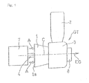
- a gas turbine engine GT to which a gas turbine combustor is applied is of a single can type as shown in Fig. 1 , but it may be of a multi-can type.
- This gas turbine engine GT includes a centrifugal compressor 1 for compressing an air A which has been sucked from an air inflow port 1a, a combustor 2 for supplying a fuel into a compressed air A to burn them, and a turbine 3 driven by a combustion gas from the combustor 2.
- the combustor 2 is disposed so as to protrude in a substantially radial direction with respect to an engine rotary shaft axis C.
- the combustion gas generated by the combustor 2 is guided into the turbine 3 to rotate the turbine 3 to thereby drive the centrifugal compressor 1, drivingly connected with the turbine 3 through a rotary shaft 4, and a load 7 such as an electric power generator.
- Exhaust gases EG having passed through the turbine 3 are discharged to the outside through an exhaust discharge duct 8.
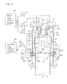
- the combustor 2 is of a reverse flow can type in which the compressed air A, guided from the centrifugal compressor 1 (best shown in Fig. 1 ) into an air passage 22, and the combustion gas G flow within the combustor 2 in respective directions reverse to each other.
- the combustor 2 includes a cylindrical housing H and a substantially cylindrical combustion barrel 9 accommodated within the housing H in coaxial relation therewith.
- the air passage 22 into which the air A is introduced from the centrifugal compressor 1 is formed between the housing H and the combustion barrel 9, and a combustion chamber 10 is formed within the combustion barrel 9.
- a burner unit (nozzle unit) 11 is fitted to the top of the combustion barrel 9.
- the burner unit 11 makes use of, as a first fuel F1, a hydrocarbon system fuel containing 60 or higher percents by volume of hydrocarbon.
- this hydrocarbon system fuel is in the form of natural gas.
- the hydrocarbon system fuel includes, besides the natural gas, a gaseous fuel in which the natural gas is mixed with about 5 % of hydrogen, and a liquid fuel such as, for example, kerosene or diesel oil.
- the burner unit 11 includes a main burner 12 and a pilot burner 13.
- the main burner 12 combusts a premixed gas or premixed air-fuel mixture M which contains the first fuel F1 for premixing purpose, supplied from a first fuel supply source 18, after the premixed gas M1 has been injected into a first combustion region S1, within the combustion chamber 10.
- the pilot burner 13 diffusively combusts the first fuel F1 after the latter has been injected directly into the first combustion region S1.
- the combustion barrel 9 includes a supplemental burner 20 for accomplishing combustion by premixing with an air A both of a second fuel F2 for reheating purpose, supplied from a second fuel supply source 19, and the first fuel F1 from the first fuel supply source 18, and then injecting such a premixed gas into a second combustion region S2 downstream of the first combustion region S1 within the combustion chamber 10.
- the supplemental burner 20 is provided in a plural number and, while those of supplemental burners 20 are disposed spaced an equal distance from each other in a direction circumferentially of the combustion barrel 9, each of them traverses the air passage 22 delimited between the housing H and the combustion barrel 9.
- a gas of a composition different from that of the first fuel F1, but containing hydrogen in a concentration exceeding the stable combustion limiting concentration, for example, in a concentration exceeding 10 vol. % is employed.
- the hydrogen concentration in the second fuel F2 is preferably 20 vol. % or higher and, more preferably, 30 vol. % or higher.
- This hydrogen containing gas is in the form of, for example, a gas containing solely a hydrogen gas (100 vol. %), or a gas in which hydrogen gas is mixed with a methane gas or propane gas or an inactive gas such as nitrogen.
- the main burner 12 referred to above is disposed so as to enclose the outer periphery of the pilot burner 13 of a cylindrical shape.
- This main burner 12 includes an L-sectioned annular outer wall 121 and an annular inner wall 122, with a premixing passage 14 delimited between the outer wall 121 and the inner wall 122.
- the premixing passage 14 has an upstream end open radially outwardly and, at allocation radially outwardly of an annular air intake opening 14a so opened, a plurality of main fuel nozzles 17 are disposed spaced an equal distance from each other in a direction circumferentially of the main burner 12.
- Respective portions of the main fuel nozzles 17, which confront the air intake opening 14a, are formed with a plurality of fuel injection holes (not shown) through which the first fuel F1 is injected towards the air intake opening 14a.
- a swirler 25 is disposed in the air intake opening 14a for promoting the premixing of the first fuel F1 by swirling an inflowing air.
- the pilot burner 13 of a diffusive combustion type is disposed within an inner space of the inner wall 122.
- the supplemental burner 20 referred to previously is of a structure in which, a fuel introducing block 20a and a collared mixture injecting barrel 20b are connected with each other through a plurality of guide pieces 20c, and is supported by the housing H by means of screwing (not shown) with a tip end of the mixture injecting barrel 20b inserted into an insertion hole 41, defined in the combustion barrel 9, so as to protrude into the combustion chamber 10.
- An air inflow opening 43 provided with the guide pieces 20c is formed between a collar 20ba of the mixture injecting barrel 20b and a bottom wall 20n of the fuel introducing block 20a.
- the air inflow opening 43 is communicated with a premixing chamber 21 defined by an inner peripheral surface of the mixture injecting barrel 20b and an outer surface of the bottom wall 20n.
- the fuel introducing block 20a is provided with a first fuel introducing passage 20d for introducing the first fuel F1 from the first fuel supply source 18 from radially outwardly of the combustor 2, a second fuel introducing passage 20e for introducing the second fuel F2 from the second fuel supply source 19 from radially outwardly of the combustor 2, a first fuel chamber 20f of a cylindrical shape for reserving the first fuel F1 from the first fuel introducing passage 20d, and a second fuel chamber 20g of a cylindrical shape for reserving the second fuel F2 from the second introducing passage 20e.
- the fuel introducing block 20a also includes a first nozzle 20h in the form of a plurality of small perforations, through which the first fuel F1 within the first fuel chamber 20f is injected into the premixing chamber 21, and a second nozzle 20i in the form of a plurality of small perforations through which the second fuel F2 within the second fuel chamber 20g is injected into the premixing chamber 21.
- the guide pieces 20c which is 12 in number, for example, in the illustrated embodiment, are provided in the vicinity of an outer peripheral edge of the fuel introducing block 20a in a fashion spaced an equal distance from each other in the circumferential direction, while having been disposed coaxially with the cylindrical mixture injecting barrel 20b that is opposed relative to the fuel introducing block 20a.
- the first nozzle 20h formed in the fuel introducing block 20a is positioned at a location between the neighboring two guide pieces 20c and somewhat closer to the longitudinal axis C1 of the fuel introducing block 20a than to the guide piece 20c. Accordingly, from the first nozzle 20h, the first fuel F1 shown in Fig.
- the first fuel F1 supplied from the first fuel supply source 18 shown in Fig. 2 is, after the flow rate thereof has been adjusted by a first fuel control valve 23, injected from the main fuel nozzle 17 into the air intake opening 14a of the premixing passage 14.
- the first fuel F1 so injected is introduced into the premixing passage 14 together with the compressed air A then flowing from the air passage 22 into the air intake opening 14a while having been swirled by the swirler 25.
- the first fuel F1 is premixed with the compressed air A while flowing within the premixing passage 14, and is finally injected into the combustion chamber 10 as a premixed gas M1 from an annular premix jetting port 24.
- the first fuel control valve 23 is closed, but only a second fuel control valve 27 is opened.
- the first fuel F1 in the first fuel supply source 18 is injected from the pilot burner 13 into the combustion chamber 10 by way of the second fuel control valve 27 and the diffusive combustion takes place upon ignition of an ignition plug (not shown).
- the premixed gas M1 injected from the main burner 12 into the combustion chamber 10 is premix-combusted and, at an upstream portion of the combustion chamber 10, the first combustion region S1 is formed.
- the main burner 12 and the pilot burner 13 are so controlled that the air to fuel ratio (air flow rate/ fuel flow rate) may attain a predetermined value that is favorable to each of them.
- This first combustion region S1 can reduce, for example, NOx and CO when the first fuel F1 is subjected to a leaned premix combustion (lean burn of the premix). Also, the first combustion region S1 does not accompany any backfiring because the first fuel F1 of the hydrocarbon system that is relatively low in combustion velocity is supplied to the main burner 12 for accomplishing the premix combustion. Therefore, in the first combustion region S1, a favorable low emission performance can be maintained.
- the second combustion region S2 for premix-combusting the premixed gas M2 injected from the supplemental burner 20 is formed on a downstream side of the first combustion region S1 in the combustion chamber 10.
- the supplemental burner 20 premixes both of the second fuel F2, which is supplied from the second fuel supply source 19 through a third fuel control valve 28, and the first fuel F1, which is supplied from the first fuel supply source 18 through a fourth control valve 29, with the compressed air A to form the premixed gas M2 which is in turn supplied to the second combustion region S2.
- This second combustion region S2 is formed so that the operating range is expanded towards a high output side in dependence on variation of the operating load of the gas turbine engine GT.
- both of the third fuel control valve 28 and the fourth fuel control valve 29 are so adjusted as to open to the opening in dependence on the variation of the operating load so that a predetermined amount of the second fuel F2 and the first fuel F1 from the respective second and first fuel supply sources 19 and 18 can be supplied to the supplemental burner 20.
- the first fuel F1 and the second fuel F2 reserved respectively within the first combustion chamber 20f and the second combustion chamber 20g are, after having been injected from the first nozzle 20h and the second nozzle 20i into the premixing chamber 21 and mixed together, premixed with the compressed air A introduced into the premixing chamber 21 from the air passage 22 by way of the air inflow opening 43. Accordingly, within the premixing chamber 21, the first fuel F1 and the second fuel F2 are sufficiently mixed with the compressed air A, then introduced from the air passage 22, to thereby form a good premixed gas M2. This premixed gas M2 is supplied from the mixture injecting barrel 20b to the second combustion region S2 within the combustion barrel 9 and is then premix-combusted.
- the hydrogen gas which is generally responsible to the generation of a large quantity of NOx, can be combusted at a low NOx.
- the supplemental burner 20 is activated under a condition in which a high temperature combustion gas G is generated as a result of general completion of combustion by the main burner 12 and the pilot burner 13, and therefore, the premixed gas M2 injected from the supplemental burner 20 has its combustion reaction accelerated stably by the high temperature combustion gas G with no flame holding mechanism.
- the first fuel F1 is added.
- a by-product hydrogen gas which is generated in a chemical plant
- the fourth fuel control valve 29 it is possible to maintain the required high output operation by opening the fourth fuel control valve 29 to supply the first fuel F 1 of the first fuel supply source 18 from the supplemental burner 20 to the second combustion region S2.
- the backfiring is generated starting at a relatively low speed site such as, for example, the boundary layer of a burner wall surface or a reverse flow area.
- the supplemental burner 20 does not require any flame holding mechanism and do not make use of a flame holder or a swirler for generating the reverse flow area. Therefore, the resistance to the backfiring from the reverse flow area is extremely high.
- the resistance to the backfiring from the reverse flow area is extremely high.
- the second preferred embodiment of the present invention is shown in Fig. 5 .
- components similar to those shown in Fig. 2 and described in connection with the previously described embodiment are designated by similar or identical reference numerals that are employed in Fig. 2 and, therefore, the details thereof are not reiterated for the sake of brevity.
- the gas turbine combustor 2A employed in the practice of this second embodiment, differs from the gas turbine combustor 2, which is shown in Fig. 2 and has been described in connection with the first embodiment, in respect of the structure of the supplemental burner 20A.
- the first and second fuels F1 and F2 are directly introduced into a mixing chamber 20j to form a mixture fuel.
- the mixture fuel so formed is injected into the premixing chamber 21 through a third nozzle 20k, and is then premixed with the compressed air A introduced from the air passage 22 to form the premixed gas M2.
- the premixing chamber 21 is formed, in a manner similar to that employed in the practice of the first embodiment, between an inner surface of the mixture injecting barrel 20b and the bottom wall 20n of the fuel introducing block 20a, which are connected with each other with the plurality of the guide pieces 20c intervening therebetween.
- the first fuel F1 and the second fuel F2 are injected into the premixing chamber 21, to which the compressed air A is introduced, to thereby form the premixed gas M.
- the first fuel F1 and the second fuel F2 are introduced into the mixing chamber 20j to form a mixture fuel beforehand and, subsequently, such mixture fuel is injected into the premixing chamber 21 to form the premixed gas M2. Accordingly, as a result of the mixture of the first and second fuels F1 and F2 having been accelerated, the premixed gas M2 that is further homogenous can be obtained.
- Fig. 6 illustrates a third preferred embodiment of the present invention. It is to be noted that in Fig. 6 , components similar to those shown in Fig. 2 and described in connection with the previously described embodiment are designated by similar or identical reference numerals that are employed in Fig. 2 and, therefore, the details thereof are not reiterated for the sake of brevity.
- the gas turbine combustor 2B employed in the practice of this third embodiment, differs from the gas turbine combustor 2, which is shown in Fig. 2 and has been described in connection with the first embodiment, in respect of the structure in which the supplemental burner 20B shown in Fig. 6 is of a two staged arrangement using a first burner 201 and a second burner 202 that are separately provided for the first fuel F1 and the second fuel F2.
- the first burner 201 includes a fuel chamber 20m, into which the first fuel F1 is introduced from a single first fuel introducing passage 20i, and a premixing chamber 21 for premixing the first fuel F1 with the compressed air A, which first fuel F1 is introduced from the fuel chamber 20m through a third nozzle 20k.
- the second burner 202 is also of an identical construction with the first burner 201 and the second fuel F2 is introduced into the fuel chamber 20m from a second fuel introducing passage 20i.
- the first fuel F1 is supplied to the first burner 201 through the fourth fuel control valve 29 and, also, the second fuel F2 is supplied to the second burner 202 through the third fuel control valve 28.
- a first reheating fuel supply passage 31 for the supply of the first fuel F1 is branched from an upstream side of the first fuel control valve 23 provided in a main fuel supply passage 30.
- a fifth fuel control valve 32 is opened to supply the first fuel F1 of the first fuel supply source 18 towards a second fuel supply side through a check valve 33 so that the first fuel F1 is mixed by a mixer 34 with the second fuel F2 fed from the second fuel supply source 19 before the resultant mixture fuel is supplied to the second burner 202.
- the gas turbine combustor 2B according to this third embodiment is such that the first reheating fuel supply passage 31 is fluid connected with the main fuel supply passage 30 at a location upstream of the first fuel control valve 23, it is possible to stably supply at all times a predetermined amount of the first fuel F1 to the supplemental burner 20B, regardless of pressure fluctuation within the main fuel supply passage 30 accompanied by an adjustment of the first fuel control valve 23.
- FIG. 7 A fourth preferred embodiment of the present invention is shown in Fig. 7 . It is to be noted that in Fig. 7 , components similar to those shown in Fig. 2 and described in connection with the previously described embodiment are designated by similar or identical reference numerals that are employed in Fig. 2 and, therefore, the details thereof are not reiterated for the sake of brevity.
- the gas turbine combustor 2C employed in the practice of this fourth embodiment, includes a plurality of supplemental burners 20C of a single stage arrangement, which is of the structure identical with each of the first burner 201 and the second burner 202 that are employed in the practice of the third embodiment shown in Fig. 6 , and also a pilot burner 13A capable of supplying the second fuel F2.
- the first fuel F1 is supplied to the pilot burner 13A through a pilot fuel supply passage 37 via the second fuel control valve 27 and a check valve 38.
- a pilot sub passage 40 for introducing the second fuel F2 through a sixth fuel control valve 39 during the activation of the main burner 12 is fluid connected with the pilot fuel supply passage 37.
- the check valve 38 is operable to permit only the flow of the first fuel F1 towards the pilot burner 13A and the supplemental burner 20B.
- this gas turbine combustor 2C includes a fifth fuel control valve 32, a check valve and a mixer, which are equivalent to the fifth fuel control valve 32, the check valve 33 and the mixer 34, respectively, employed in the practice of the third embodiment shown in Fig. 6 .
- the second fuel F2 containing the hydrogen gas is supplied to the pilot burner 13A through the sixth fuel control valve 39. Therefore, combustion occurring in the pilot burner 13A is stabilized by the hydrogen gas having a high combustion temperature.
Abstract
Description
- The present invention relates to a multifuel gas turbine combustor operable with the efficient utilization of hydrogen containing fuel while securing a low emission performance.
- In the field of combustors in gas turbine engines, a technology for securing a low emission performance including a low NOx emission has hitherto been known, which includes, besides a wet type combustor, in which water or steam is injected into the combustor, a dry low emission (DLE) combustor in which a pre-mixture formed by mixing fuel with compressed air is injected into a combustion chamber to accomplish a leaned pre-mixture combustion, that is, a lean burn of the pre-mixture. This dry low emission combustor makes use of hydrocarbon system fuel such as, for example, natural gas, kerosene or diesel oil as a fuel for use in the dry low emission combustor.
- In the meantime, in recent years, the efficient utilization of the hydrogen gas emitted in chemical plants as a fuel for use in the gas turbine combustor is desired for. As a gas turbine combustor utilizing the hydrogen gas as a fuel therefor, such a combustor as disclosed in the
patent document 1 listed below has been known in the art. - Gas such as, for example, hydrogen gas is generally high in combustion velocity as compared with that of the previously mentioned hydrocarbon system fuel. Accordingly, if a substantial amount of the hydrogen gas is mixed in the fuel for the dry low emission combustor, there is a possibility that the back firing phenomenon may occur in which flames propagate through a relatively long premixing passage to such an extent as to result in heating and/or impairment. In contrast thereto, the
patent document 1 referred to above discloses the utilization of the diffusive combustion to minimize the risk of back firing phenomenon while the hydrogen gas is used as a fuel therefor. In other words, thepatent document 1 referred to above discloses a technique that is remotely far from the leaned pre-mixture combustion. - In view of the foregoing, the present invention has for its primary object to provide a multifuel gas turbine combustor, that is, a gas turbine combustor capable of operating with multifuel pre-mixture, which can combust gases containing hydrogen in a high concentration with a low NOx while maintaining a low emission performance brought about by the pre-mixture combustion.
- In order to accomplish the foregoing object of the present invention, the present invention provides a multifuel gas turbine combustor which includes a main burner to supply a premixed gas, containing a first fuel, to a first combustion region within a combustion chamber and then to combust the premixed gas, and a supplemental burner to supply a premixed gas, containing a second fuel of a composition different from that of the first fuel, to a second combustion region at a location downstream of the first combustion region within the combustion chamber and then to combust the premixed gas. In this gas turbine compressor, the first fuel is of a hydrocarbon system and the second fuel is a gas containing hydrogen in concentration exceeding a stable combustion limiting concentration of the hydrogen. It is to be noted that the term "hydrocarbon system" referred to above and hereinafter means a gas containing hydrocarbons in a quantity equal to or higher than 60 percents by volume with the hydrogen gas not higher than the stable combustion limiting concentration, or a liquid containing hydrocarbons in a quantity equal to or higher than 60 percents by volume. It is also to be noted that the stable combustion limiting concentration of hydrogen referred to above and hereinafter stands for the hydrogen concentration (volume %) at the upper limit of the boundary of whether the stable combustion is impaired as a result of the occurrence of a backfiring or is maintained when a premix containing hydrogen is formed within a main burner including a flame holding mechanism and a swirler. This stable combustion limiting concentration of the hydrogen is generally within the range of 8 to 15 percents by volume, but about 10 percents by weight in the embodiments of the present invention.
- In this gas turbine combustor, since the first fuel of the hydrocarbon system, which is relatively low in combustion velocity, is supplied to the main burner for supplying and combusting the premixed gas in the first combustion region, there is no risk of backfiring occurring and, therefore, a good low emission performance can be maintained. On the other hand, where the operating range is expanded towards a high output side in dependence the increase of an engine load, the premixed gas, in which the air is mixed into the second fuel, is supplied from the supplemental burner and combusted in the second combustion region and, therefore, the second furl containing the hydrogen gas, which is high in combustion velocity, can be combusted at a low combustion temperature by the introduction of the air. As a result, the hydrogen gas generally tending to emit a large emission of NOx can be combusted at a low NOx, that is, at a low emission. It is further to be noted that the term "composition different" means that the difference exists in content of the principal component or element. In addition, since the supplemental burner is activated while a high temperature combustion gas is generated upon substantial completion of combustion in the main burner, the combustion reaction of the premixed gas injected from the supplemental burner is stably accelerated in the presence of the high temperature combustion gas without the flame holding mechanism employed. By this reason, even when as the second fuel the gas containing the hydrogen exceeding the stable combustion limiting concentration is used, there is no risk of the backfiring occurring.
- In a preferred embodiment of the present invention, the supplemental burner may be a premixing burner operable to premix both of the first fuel and the second fuel with an air and supplying it to the second combustion region. The use of the premixing burner for the supplemental burner makes it possible that in the event of shortage of one of the first fuel and the second fuel, mixing an air into one of the first and second fuels, which is sufficient in quantity, and then supplying it into the second combustion region is satisfactory. For example, where the second fuel is employed in the form of a by-product hydrogen gas, which is generated in a chemical plant, in the event of the shortage of the second fuel by reason of the operation of the chemical plant being halted, a required high output operation can be maintained by supplying the first fuel from the supplemental burner into the second combustion region.
- In another preferred embodiment of the present invention, where both of the first and second fuels are supplied to the supplemental burner, the supplemental burner may include a premixing chamber to which the air is introduced, a first nozzle to inject the first fuel into the premixing chamber, and a second nozzle to inject the second fuel into the premixing chamber. By so doing, in the premixing chamber, the first fuel, injected from the first nozzle, and the second fuel, injected from the second nozzle, are sufficiently mixed with the air then introduced into the premixing chamber to provide a good premixed gas, which premixed gas is supplied to the second combustion region.
- Similarly where both of the first and second fuels are supplied to the supplemental burner, the supplemental burner may include a mixing chamber to which the first fuel and the second fuel are introduced, and the premixing chamber to premix the mixed fuel with the air. By so doing, after the first fuel and the second fuel have been introduced into and premixed together within the mixing chamber, the mixed fuel is introduced into the premixing chamber and is then premixed with the air. Therefore, the premixed gas containing the first fuel, the second fuel and the air uniformly distributed over the entirety can be generated.
- Furthermore where both of the first and second fuels are supplied to the supplemental burner, the supplemental burner may include a first burner to premix the first fuel with the air and then to inject it, and a second burner to premix the second fuel with the air and then to inject it. By so doing, the structure of each of the first burner and the second burner can be simplified.
- In a further preferred embodiment of the present invention, particularly where both of the first and second fuels are supplied to the supplemental burner, the gas turbine combustor of the present invention may further include a main fuel supply passage to supply the first fuel to the main burner, a first fuel control valve provided in the main fuel supply passage, and a first reheating fuel supply passage to supply the first fuel to the supplemental burner, the first reheating fuel supply passage being branched off from an upstream side of the first fuel control valve in the main fuel supply passage. According to this structural feature, regardless of the variation in pressure inside the main fuel supply passage resulting from the adjustment of the first fuel control valve, the required quantity of the first fuel can be supplied stably at all times to the supplemental burner.
- In a still further preferred embodiment of the present invention, the gas turbine combustor may further include a pilot burner to inject the first fuel into the first combustion region and then to accomplish a diffusion combustion thereof, and a pilot sub passage disposed in a pilot fuel supply passage to supply the first fuel to the pilot burner to introduce the second fuel during activation of the main burner. According to this structural feature, since the second fuel containing the hydrogen gas is supplied to the pilot burner of a diffusion combustion system, the combustion within the pilot burner can be stabilized by the hydrogen gas that is high in combustion temperature.
- Any combination of at least two constructions, disclosed in the appended claims and/or the specification and/or the accompanying drawings should be construed as included within the scope of the present invention. In particular, any combination of two or more of the appended claims should be equally construed as included within the scope of the present invention.
- In any event, the present invention will become more clearly understood from the following description of preferred embodiments thereof, when taken in conjunction with the accompanying drawings. However, the embodiments and the drawings are given only for the purpose of illustration and explanation, and are not to be taken as limiting the scope of the present invention in any way whatsoever, which scope is to be determined by the appended claims. In the accompanying drawings, like reference numerals are used to denote like parts throughout the several views, and:
-
Fig. 1 is a schematic structural diagram showing a gas turbine engine to which a gas turbine combustor of the present invention is applied; -
Fig. 2 is a schematic longitudinal sectional view showing the gas turbine combustor, designed in accordance with a first preferred embodiment of the present invention, shown together with a fuel supply system therefor; -
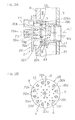
Fig. 3A is a fragmentary enlarged diagram showing a portion ofFig. 2 ; -
Fig. 3B is a cross sectional view taken along the line III-III inFig. 3A ; -
Fig. 4 is a characteristic chart showing the relationship between a load variation in the gas turbine engine and the fuel consumption of a second fuel corresponding therewith; -
Fig. 5 is a schematic longitudinal sectional view showing the gas turbine combustor, designed in accordance with a second preferred embodiment of the present invention, shown together with a fuel supply system therefor; -
Fig. 6 is a schematic longitudinal sectional view showing the gas turbine combustor, designed in accordance with a third preferred embodiment of the present invention, shown together with a fuel supply system therefor; and -
Fig. 7 is a schematic longitudinal sectional view showing the gas turbine combustor, designed in accordance with a fourth preferred embodiment of the present invention, shown together with a fuel supply system therefor. - Hereinafter, some preferred embodiments of the present invention will be described in detail with particular reference to the accompanying drawings. It is, however, to be noted that in the practice of the embodiments of the present invention, a gas turbine engine GT to which a gas turbine combustor is applied is of a single can type as shown in
Fig. 1 , but it may be of a multi-can type. This gas turbine engine GT includes acentrifugal compressor 1 for compressing an air A which has been sucked from an air inflow port 1a, acombustor 2 for supplying a fuel into a compressed air A to burn them, and aturbine 3 driven by a combustion gas from thecombustor 2. Thecombustor 2 is disposed so as to protrude in a substantially radial direction with respect to an engine rotary shaft axis C. The combustion gas generated by thecombustor 2 is guided into theturbine 3 to rotate theturbine 3 to thereby drive thecentrifugal compressor 1, drivingly connected with theturbine 3 through a rotary shaft 4, and aload 7 such as an electric power generator. Exhaust gases EG having passed through theturbine 3 are discharged to the outside through anexhaust discharge duct 8. - As shown in
Fig. 2 , thecombustor 2 is of a reverse flow can type in which the compressed air A, guided from the centrifugal compressor 1 (best shown inFig. 1 ) into anair passage 22, and the combustion gas G flow within thecombustor 2 in respective directions reverse to each other. Thecombustor 2 includes a cylindrical housing H and a substantiallycylindrical combustion barrel 9 accommodated within the housing H in coaxial relation therewith. Theair passage 22 into which the air A is introduced from thecentrifugal compressor 1 is formed between the housing H and thecombustion barrel 9, and acombustion chamber 10 is formed within thecombustion barrel 9. A burner unit (nozzle unit) 11 is fitted to the top of thecombustion barrel 9. - The
burner unit 11 makes use of, as a first fuel F1, a hydrocarbon system fuel containing 60 or higher percents by volume of hydrocarbon. In the practice of the embodiment, this hydrocarbon system fuel is in the form of natural gas. The hydrocarbon system fuel includes, besides the natural gas, a gaseous fuel in which the natural gas is mixed with about 5 % of hydrogen, and a liquid fuel such as, for example, kerosene or diesel oil. Theburner unit 11 includes amain burner 12 and apilot burner 13. Themain burner 12 combusts a premixed gas or premixed air-fuel mixture M which contains the first fuel F1 for premixing purpose, supplied from a firstfuel supply source 18, after the premixed gas M1 has been injected into a first combustion region S1, within thecombustion chamber 10. Thepilot burner 13 diffusively combusts the first fuel F1 after the latter has been injected directly into the first combustion region S1. - Also, the
combustion barrel 9 includes asupplemental burner 20 for accomplishing combustion by premixing with an air A both of a second fuel F2 for reheating purpose, supplied from a secondfuel supply source 19, and the first fuel F1 from the firstfuel supply source 18, and then injecting such a premixed gas into a second combustion region S2 downstream of the first combustion region S1 within thecombustion chamber 10. Thesupplemental burner 20 is provided in a plural number and, while those ofsupplemental burners 20 are disposed spaced an equal distance from each other in a direction circumferentially of thecombustion barrel 9, each of them traverses theair passage 22 delimited between the housing H and thecombustion barrel 9. For the second fuel F2, a gas of a composition different from that of the first fuel F1, but containing hydrogen in a concentration exceeding the stable combustion limiting concentration, for example, in a concentration exceeding 10 vol. % is employed. The hydrogen concentration in the second fuel F2 is preferably 20 vol. % or higher and, more preferably, 30 vol. % or higher. This hydrogen containing gas is in the form of, for example, a gas containing solely a hydrogen gas (100 vol. %), or a gas in which hydrogen gas is mixed with a methane gas or propane gas or an inactive gas such as nitrogen. - The
main burner 12 referred to above is disposed so as to enclose the outer periphery of thepilot burner 13 of a cylindrical shape. Thismain burner 12 includes an L-sectioned annularouter wall 121 and an annularinner wall 122, with apremixing passage 14 delimited between theouter wall 121 and theinner wall 122. Thepremixing passage 14 has an upstream end open radially outwardly and, at allocation radially outwardly of an annularair intake opening 14a so opened, a plurality ofmain fuel nozzles 17 are disposed spaced an equal distance from each other in a direction circumferentially of themain burner 12. Respective portions of themain fuel nozzles 17, which confront theair intake opening 14a, are formed with a plurality of fuel injection holes (not shown) through which the first fuel F1 is injected towards theair intake opening 14a. In theair intake opening 14a, aswirler 25 is disposed for promoting the premixing of the first fuel F1 by swirling an inflowing air. Thepilot burner 13 of a diffusive combustion type is disposed within an inner space of theinner wall 122. - As shown in
Fig. 3A , thesupplemental burner 20 referred to previously is of a structure in which, afuel introducing block 20a and a collaredmixture injecting barrel 20b are connected with each other through a plurality ofguide pieces 20c, and is supported by the housing H by means of screwing (not shown) with a tip end of themixture injecting barrel 20b inserted into an insertion hole 41, defined in thecombustion barrel 9, so as to protrude into thecombustion chamber 10. Anair inflow opening 43 provided with theguide pieces 20c is formed between a collar 20ba of themixture injecting barrel 20b and abottom wall 20n of thefuel introducing block 20a. Theair inflow opening 43 is communicated with a premixingchamber 21 defined by an inner peripheral surface of themixture injecting barrel 20b and an outer surface of thebottom wall 20n. - The
fuel introducing block 20a is provided with a firstfuel introducing passage 20d for introducing the first fuel F1 from the firstfuel supply source 18 from radially outwardly of thecombustor 2, a secondfuel introducing passage 20e for introducing the second fuel F2 from the secondfuel supply source 19 from radially outwardly of thecombustor 2, afirst fuel chamber 20f of a cylindrical shape for reserving the first fuel F1 from the firstfuel introducing passage 20d, and asecond fuel chamber 20g of a cylindrical shape for reserving the second fuel F2 from the second introducingpassage 20e. Thefuel introducing block 20a also includes afirst nozzle 20h in the form of a plurality of small perforations, through which the first fuel F1 within thefirst fuel chamber 20f is injected into the premixingchamber 21, and a second nozzle 20i in the form of a plurality of small perforations through which the second fuel F2 within thesecond fuel chamber 20g is injected into the premixingchamber 21. - As shown in
Fig. 3B , theguide pieces 20c, which is 12 in number, for example, in the illustrated embodiment, are provided in the vicinity of an outer peripheral edge of thefuel introducing block 20a in a fashion spaced an equal distance from each other in the circumferential direction, while having been disposed coaxially with the cylindricalmixture injecting barrel 20b that is opposed relative to thefuel introducing block 20a. Thefirst nozzle 20h formed in thefuel introducing block 20a is positioned at a location between the neighboring twoguide pieces 20c and somewhat closer to the longitudinal axis C1 of thefuel introducing block 20a than to theguide piece 20c. Accordingly, from thefirst nozzle 20h, the first fuel F1 shown inFig. 3A is injected towards the stream of the compressed air A introduced through anair inflow opening 43. From the second nozzle 20i, the second fuel F2 is sprayed towards a center portion of the premixingchamber 21 in a direction parallel to the longitudinal axis C1. Accordingly, a smooth mixing of the first fuel F1 and the second fuel F2 with the compressed air A is accelerated. Since the compressed air A introduced through theair inflow opening 43 is deflected 90° after having passed through theguide piece 20c, a turbulent flow occurs so that the mixing of the first fuel F1 and the second fuel F2 is accelerated. - Hereinafter, the operation will be described. The first fuel F1 supplied from the first
fuel supply source 18 shown inFig. 2 is, after the flow rate thereof has been adjusted by a firstfuel control valve 23, injected from themain fuel nozzle 17 into theair intake opening 14a of thepremixing passage 14. The first fuel F1 so injected is introduced into thepremixing passage 14 together with the compressed air A then flowing from theair passage 22 into theair intake opening 14a while having been swirled by theswirler 25. The first fuel F1 is premixed with the compressed air A while flowing within thepremixing passage 14, and is finally injected into thecombustion chamber 10 as a premixed gas M1 from an annularpremix jetting port 24. - At the time the gas turbine engine GT is started, the first
fuel control valve 23 is closed, but only a secondfuel control valve 27 is opened. Under this condition, the first fuel F1 in the firstfuel supply source 18 is injected from thepilot burner 13 into thecombustion chamber 10 by way of the secondfuel control valve 27 and the diffusive combustion takes place upon ignition of an ignition plug (not shown). During a normal operation, while the supply of the first fuel F1 from thepilot burner 13 is continued, with flames thereof used as a pilot fire, the premixed gas M1 injected from themain burner 12 into thecombustion chamber 10 is premix-combusted and, at an upstream portion of thecombustion chamber 10, the first combustion region S1 is formed. Themain burner 12 and thepilot burner 13 are so controlled that the air to fuel ratio (air flow rate/ fuel flow rate) may attain a predetermined value that is favorable to each of them. - This first combustion region S1 can reduce, for example, NOx and CO when the first fuel F1 is subjected to a leaned premix combustion (lean burn of the premix). Also, the first combustion region S1 does not accompany any backfiring because the first fuel F1 of the hydrocarbon system that is relatively low in combustion velocity is supplied to the
main burner 12 for accomplishing the premix combustion. Therefore, in the first combustion region S1, a favorable low emission performance can be maintained. - On a downstream side of the first combustion region S1 in the
combustion chamber 10, the second combustion region S2 for premix-combusting the premixed gas M2 injected from thesupplemental burner 20 is formed. Thesupplemental burner 20 premixes both of the second fuel F2, which is supplied from the secondfuel supply source 19 through a thirdfuel control valve 28, and the first fuel F1, which is supplied from the firstfuel supply source 18 through afourth control valve 29, with the compressed air A to form the premixed gas M2 which is in turn supplied to the second combustion region S2. - This second combustion region S2 is formed so that the operating range is expanded towards a high output side in dependence on variation of the operating load of the gas turbine engine GT. In the event that the increase of an operating load of the gas turbine engine GT exceeds a predetermined value, both of the third
fuel control valve 28 and the fourthfuel control valve 29 are so adjusted as to open to the opening in dependence on the variation of the operating load so that a predetermined amount of the second fuel F2 and the first fuel F1 from the respective second and firstfuel supply sources supplemental burner 20. AsFig. 4 makes it clear the fuel consumption of the second fuel F2 increases with the increase of the operating load of the engine GT, and therefore, a large quantity of the hydrogen gas, which is not sufficiently utilized at that time during a high load, can be consumed as the second fuel F2 for thecombustor 2. In such case, regardless of whether the amount of supply of the second fuel F2 in the second combustion region S2 is large or small, the flame holding performance of the first combustion region S1 is secured by themain burner 12 and thepilot burner 13. - In the
supplemental burner 20, the first fuel F1 and the second fuel F2 reserved respectively within thefirst combustion chamber 20f and thesecond combustion chamber 20g are, after having been injected from thefirst nozzle 20h and the second nozzle 20i into the premixingchamber 21 and mixed together, premixed with the compressed air A introduced into the premixingchamber 21 from theair passage 22 by way of theair inflow opening 43. Accordingly, within the premixingchamber 21, the first fuel F1 and the second fuel F2 are sufficiently mixed with the compressed air A, then introduced from theair passage 22, to thereby form a good premixed gas M2. This premixed gas M2 is supplied from themixture injecting barrel 20b to the second combustion region S2 within thecombustion barrel 9 and is then premix-combusted. - Here, where only the second fuel F2 is supplied to the
supplemental burner 20, as a result that the second fuel F2 containing the hydrogen gas having a high combustion velocity is combusted at a low combustion temperature by the introduction of the compressed air A, the hydrogen gas, which is generally responsible to the generation of a large quantity of NOx, can be combusted at a low NOx. Also, thesupplemental burner 20 is activated under a condition in which a high temperature combustion gas G is generated as a result of general completion of combustion by themain burner 12 and thepilot burner 13, and therefore, the premixed gas M2 injected from thesupplemental burner 20 has its combustion reaction accelerated stably by the high temperature combustion gas G with no flame holding mechanism. By those reasons, there is no risk of backfiring even when a fuel such as, for example, hydrogen is used as the second fuel F2. - In this
combustor 2, in the event of shortage of the second fuel F2, the first fuel F1 is added. For example, where a by-product hydrogen gas, which is generated in a chemical plant, is used as the second fuel F2, in the event of shortage of this second fuel F2 as a result of the halt of operation of the chemical plant, it is possible to maintain the required high output operation by opening the fourthfuel control valve 29 to supply thefirst fuel F 1 of the firstfuel supply source 18 from thesupplemental burner 20 to the second combustion region S2. - In the meanwhile, it has been well known that the backfiring is generated starting at a relatively low speed site such as, for example, the boundary layer of a burner wall surface or a reverse flow area. As it has been made clear from the discussion made above, the
supplemental burner 20 does not require any flame holding mechanism and do not make use of a flame holder or a swirler for generating the reverse flow area. Therefore, the resistance to the backfiring from the reverse flow area is extremely high. By reducing the fuel concentration in the vicinity of the boundary layer, that is, in the vicinity of the inner peripheral surface of themixture injecting barrel 20b through the arrangement of the fuel jetting hole of thesupplemental burner 20, the resistance to the backfiring from the boundary layer, which occurs in the vicinity of that inner surface, can be increased. For those reasons, in thesupplemental burner 20 employed in the embodiment, while the leaned premix combustion system is employed, even the hydrogen gas having a relatively high concentration can be utilized as a fuel without the backfiring being accompanied. - The second preferred embodiment of the present invention is shown in
Fig. 5 . It is to be noted that inFig. 5 , components similar to those shown inFig. 2 and described in connection with the previously described embodiment are designated by similar or identical reference numerals that are employed inFig. 2 and, therefore, the details thereof are not reiterated for the sake of brevity. Thegas turbine combustor 2A, employed in the practice of this second embodiment, differs from thegas turbine combustor 2, which is shown inFig. 2 and has been described in connection with the first embodiment, in respect of the structure of thesupplemental burner 20A. In other words, without reserving the first fuel F1 from the firstfuel introducing passage 20d and the second fuel F2 from the secondfuel introducing passage 20e, the first and second fuels F1 and F2 are directly introduced into a mixing chamber 20j to form a mixture fuel. The mixture fuel so formed is injected into the premixingchamber 21 through athird nozzle 20k, and is then premixed with the compressed air A introduced from theair passage 22 to form the premixed gas M2. The premixingchamber 21 is formed, in a manner similar to that employed in the practice of the first embodiment, between an inner surface of themixture injecting barrel 20b and thebottom wall 20n of thefuel introducing block 20a, which are connected with each other with the plurality of theguide pieces 20c intervening therebetween. - In the
supplemental burner 20 employed in the practice of the first embodiment, after the first fuel F1 and the second fuel F2 have been temporarily reserved respectively within thefirst fuel chamber 20f and thesecond fuel chamber 20g, the first fuel F1 and the second fuel F2 are injected into the premixingchamber 21, to which the compressed air A is introduced, to thereby form the premixed gas M. In contrast thereto, in the practice of this second embodiment, the first fuel F1 and the second fuel F2 are introduced into the mixing chamber 20j to form a mixture fuel beforehand and, subsequently, such mixture fuel is injected into the premixingchamber 21 to form the premixed gas M2. Accordingly, as a result of the mixture of the first and second fuels F1 and F2 having been accelerated, the premixed gas M2 that is further homogenous can be obtained. -
Fig. 6 illustrates a third preferred embodiment of the present invention. It is to be noted that inFig. 6 , components similar to those shown inFig. 2 and described in connection with the previously described embodiment are designated by similar or identical reference numerals that are employed inFig. 2 and, therefore, the details thereof are not reiterated for the sake of brevity. Thegas turbine combustor 2B, employed in the practice of this third embodiment, differs from thegas turbine combustor 2, which is shown inFig. 2 and has been described in connection with the first embodiment, in respect of the structure in which thesupplemental burner 20B shown inFig. 6 is of a two staged arrangement using afirst burner 201 and asecond burner 202 that are separately provided for the first fuel F1 and the second fuel F2. Thefirst burner 201 includes afuel chamber 20m, into which the first fuel F1 is introduced from a single first fuel introducing passage 20i, and apremixing chamber 21 for premixing the first fuel F1 with the compressed air A, which first fuel F1 is introduced from thefuel chamber 20m through athird nozzle 20k. - The
second burner 202 is also of an identical construction with thefirst burner 201 and the second fuel F2 is introduced into thefuel chamber 20m from a second fuel introducing passage 20i. The first fuel F1 is supplied to thefirst burner 201 through the fourthfuel control valve 29 and, also, the second fuel F2 is supplied to thesecond burner 202 through the thirdfuel control valve 28. A first reheatingfuel supply passage 31 for the supply of the first fuel F1 is branched from an upstream side of the firstfuel control valve 23 provided in a mainfuel supply passage 30. Also, in thisgas turbine combustor 2B, in the event of shortage of the second fuel F2, a fifthfuel control valve 32 is opened to supply the first fuel F1 of the firstfuel supply source 18 towards a second fuel supply side through acheck valve 33 so that the first fuel F1 is mixed by amixer 34 with the second fuel F2 fed from the secondfuel supply source 19 before the resultant mixture fuel is supplied to thesecond burner 202. - Since the
gas turbine combustor 2B according to this third embodiment is such that the first reheatingfuel supply passage 31 is fluid connected with the mainfuel supply passage 30 at a location upstream of the firstfuel control valve 23, it is possible to stably supply at all times a predetermined amount of the first fuel F1 to thesupplemental burner 20B, regardless of pressure fluctuation within the mainfuel supply passage 30 accompanied by an adjustment of the firstfuel control valve 23. - A fourth preferred embodiment of the present invention is shown in
Fig. 7 . It is to be noted that inFig. 7 , components similar to those shown inFig. 2 and described in connection with the previously described embodiment are designated by similar or identical reference numerals that are employed inFig. 2 and, therefore, the details thereof are not reiterated for the sake of brevity. Thegas turbine combustor 2C, employed in the practice of this fourth embodiment, includes a plurality ofsupplemental burners 20C of a single stage arrangement, which is of the structure identical with each of thefirst burner 201 and thesecond burner 202 that are employed in the practice of the third embodiment shown inFig. 6 , and also apilot burner 13A capable of supplying the second fuel F2. The first fuel F1 is supplied to thepilot burner 13A through a pilotfuel supply passage 37 via the secondfuel control valve 27 and acheck valve 38. Apilot sub passage 40 for introducing the second fuel F2 through a sixthfuel control valve 39 during the activation of themain burner 12 is fluid connected with the pilotfuel supply passage 37. Thecheck valve 38 is operable to permit only the flow of the first fuel F1 towards thepilot burner 13A and thesupplemental burner 20B. It is to be noted that thisgas turbine combustor 2C includes a fifthfuel control valve 32, a check valve and a mixer, which are equivalent to the fifthfuel control valve 32, thecheck valve 33 and themixer 34, respectively, employed in the practice of the third embodiment shown inFig. 6 . - In the
gas turbine combustor 2C according to this fourth embodiment, besides the supply of the first fuel F1 through the secondfuel control valve 27 and thecheck valve 38, the second fuel F2 containing the hydrogen gas is supplied to thepilot burner 13A through the sixthfuel control valve 39. Therefore, combustion occurring in thepilot burner 13A is stabilized by the hydrogen gas having a high combustion temperature. - Although the present invention has been fully described in connection with the preferred embodiments thereof with reference to the accompanying drawings which are used only for the purpose of illustration, those skilled in the art will readily conceive numerous changes and modifications within the framework of obviousness upon the reading of the specification herein presented of the present invention. Accordingly, such changes and modifications are, unless they depart from the scope of the present invention as delivered from the claims annexed hereto, to be construed as included therein.
-
- 2, 2A, 2B, 2C
- Combustor
- 10
- Combustion chamber
- 12
- Main burner
- 13, 13A
- Pilot burner
- 14
- Premixing passage
- 20, 20A, 20B
- Supplemental burner
- 23
- First fuel control valve
- 30
- Main fuel supply passage
- 31
- First reheating fuel supply passage
- 37
- Pilot fuel supply passage
- 40
- Pilot sub passage
- S1
- First combustion region
- S2
- Second combustion region
- 201
- First burner
- 202
- Second burner
- M1, M2
- Premixed gas
- Further aspects are:
- A. A gas turbine combustor which comprises:
- a main burner to supply a premixed gas, containing a first fuel, to a first combustion region within a combustion chamber and then to combust the premixed gas; and
- a supplemental burner to supply a premixed gas, containing a second fuel of a composition different from that of the first fuel, to a second combustion region at a location downstream of the first combustion region within the combustion chamber and then to combust the premixed gas;
- in which the first fuel is of a hydrocarbon system and the second fuel is a gas containing hydrogen in concentration exceeding a stable combustion limiting concentration of the hydrogen.
- B. The gas turbine combustor according to A., in which the supplemental burner is a premixing burner operable to premix both of the first fuel and the second fuel with an air and supplying it to the second combustion region.
- C. The gas turbine combustor according to B., in which the supplemental burner comprises a premixing chamber to which the air is introduced, a first nozzle to inject the first fuel into the premixing chamber, and a second nozzle to inject the second fuel into the premixing chamber.
- D. The gas turbine combustor according to B., in which the supplemental burner comprises a mixing chamber to which the first fuel and the second fuel are introduced, and the premixing chamber to premix the mixed fuel with the air.
- E. The gas turbine combustor according to B., in which the supplemental burner comprises a first burner to premix the first fuel with the air and then to inject it, and a second burner to premix the second fuel with the air and then to inject it.
- F. The gas turbine combustor according to B. to D., further comprising:
- a main fuel supply passage to supply the first fuel to the main burner;
- a first fuel control valve provided in the main fuel supply passage; and
- a first reheating fuel supply passage to supply the first fuel to the supplemental burner, the first reheating fuel supply passage being branched off from an upstream side of the first fuel control valve in the main fuel supply passage.
- G. The gas turbine combustor according to A. to F., further comprising a pilot burner to inject the first fuel into the first combustion region and then to accomplish a diffusion combustion thereof, and a pilot sub passage disposed in a pilot fuel supply passage to supply the first fuel to the pilot burner to introduce the second fuel during activation of the main burner.
Claims (5)
- A gas turbine combustor which comprises:a main burner to supply a premixed gas, containing a first fuel, to a first combustion region within a combustion chamber and then to combust the premixed gas; anda supplemental burner to supply a premixed gas, containing a second fuel of a composition different from that of the first fuel, to a second combustion region at a location downstream of the first combustion region within the combustion chamber and then to combust the premixed gas;in which the first fuel is of a hydrocarbon system and the second fuel is a gas containing hydrogen in concentration exceeding a stable combustion limiting concentration of the hydrogen, andin which the supplemental burner is a premixing burner operable to premix both of the first fuel and the second fuel with an air and supplying it to the second combustion region.
- The gas turbine combustor as claimed in claim 1, in which the supplemental burner comprises a mixing chamber to which the first fuel and the second fuel are introduced, and the premixing chamber to premix the mixed fuel with the air.
- The gas turbine combustor as claimed in claim 1, in which the supplemental burner comprises a first burner to premix the first fuel with the air and then to inject it, and a second burner to premix the second fuel with the air and then to inject it.
- The gas turbine combustor as claimed in any one of claims 1 to 3, further comprising:a main fuel supply passage to supply the first fuel to the main burner;a first fuel control valve provided in the main fuel supply passage; anda first reheating fuel supply passage to supply the first fuel to the supplemental burner, the first reheating fuel supply passage being branched off from an upstream side of the first fuel control valve in the main fuel supply passage.
- The gas turbine combustor as claimed in any one of claims 1 to 4, further comprising a pilot burner to inject the first fuel into the first combustion region and then to accomplish a diffusion combustion thereof, and a pilot sub passage disposed in a pilot fuel supply passage to supply the first fuel to the pilot burner to introduce the second fuel during activation of the main burner.
Priority Applications (1)
| Application Number | Priority Date | Filing Date | Title |
|---|---|---|---|
| EP15168221.8A EP2955445B1 (en) | 2014-06-12 | 2014-06-12 | Multifuel gas turbine combustor |
Applications Claiming Priority (3)
| Application Number | Priority Date | Filing Date | Title |
|---|---|---|---|
| EP14844741.0A EP2902708B1 (en) | 2014-06-12 | 2014-06-12 | Multi-fuel-supporting gas-turbine combustor |
| PCT/JP2014/065657 WO2015037295A1 (en) | 2014-06-12 | 2014-06-12 | Multi-fuel-supporting gas-turbine combustor |
| EP15168221.8A EP2955445B1 (en) | 2014-06-12 | 2014-06-12 | Multifuel gas turbine combustor |
Related Parent Applications (2)
| Application Number | Title | Priority Date | Filing Date |
|---|---|---|---|
| EP14844741.0A Division EP2902708B1 (en) | 2014-06-12 | 2014-06-12 | Multi-fuel-supporting gas-turbine combustor |
| EP14844741.0A Division-Into EP2902708B1 (en) | 2014-06-12 | 2014-06-12 | Multi-fuel-supporting gas-turbine combustor |
Publications (2)
| Publication Number | Publication Date |
|---|---|
| EP2955445A1 true EP2955445A1 (en) | 2015-12-16 |
| EP2955445B1 EP2955445B1 (en) | 2019-11-27 |
Family
ID=52665420
Family Applications (2)
| Application Number | Title | Priority Date | Filing Date |
|---|---|---|---|
| EP15168221.8A Active EP2955445B1 (en) | 2014-06-12 | 2014-06-12 | Multifuel gas turbine combustor |
| EP14844741.0A Active EP2902708B1 (en) | 2014-06-12 | 2014-06-12 | Multi-fuel-supporting gas-turbine combustor |
Family Applications After (1)
| Application Number | Title | Priority Date | Filing Date |
|---|---|---|---|
| EP14844741.0A Active EP2902708B1 (en) | 2014-06-12 | 2014-06-12 | Multi-fuel-supporting gas-turbine combustor |
Country Status (6)
| Country | Link |
|---|---|
| US (2) | US9400113B2 (en) |
| EP (2) | EP2955445B1 (en) |
| JP (1) | JP5759651B1 (en) |
| CN (1) | CN105452775B (en) |
| CA (1) | CA2885287C (en) |
| WO (1) | WO2015037295A1 (en) |
Families Citing this family (34)
| Publication number | Priority date | Publication date | Assignee | Title |
|---|---|---|---|---|
| EP2955445B1 (en) | 2014-06-12 | 2019-11-27 | Kawasaki Jukogyo Kabushiki Kaisha | Multifuel gas turbine combustor |
| US20160047317A1 (en) * | 2014-08-14 | 2016-02-18 | General Electric Company | Fuel injector assemblies in combustion turbine engines |
| JP6516996B2 (en) * | 2014-10-10 | 2019-05-22 | 川崎重工業株式会社 | Combustor and gas turbine engine |
| JP6637905B2 (en) | 2014-12-25 | 2020-01-29 | 川崎重工業株式会社 | Burners, combustors, and gas turbines |
| US10060629B2 (en) * | 2015-02-20 | 2018-08-28 | United Technologies Corporation | Angled radial fuel/air delivery system for combustor |
| CN107735618B (en) * | 2015-07-06 | 2020-06-26 | 西门子股份公司 | Combustor for a gas turbine and method of operating a combustor |
| EP3220050A1 (en) * | 2016-03-16 | 2017-09-20 | Siemens Aktiengesellschaft | Burner for a gas turbine |
| JP6562883B2 (en) | 2016-09-20 | 2019-08-21 | 株式会社東芝 | Characteristic value estimation device and characteristic value estimation method |
| EP3301374A1 (en) * | 2016-09-29 | 2018-04-04 | Siemens Aktiengesellschaft | A pilot burner assembly with pilot-air supply |
| US10508811B2 (en) * | 2016-10-03 | 2019-12-17 | United Technologies Corporation | Circumferential fuel shifting and biasing in an axial staged combustor for a gas turbine engine |
| CN107023854B (en) * | 2016-12-26 | 2019-08-23 | 南方科技大学 | A kind of radial air inlet spiral-flow type tubule premix fuel nozzle |
| US10415833B2 (en) | 2017-02-16 | 2019-09-17 | General Electric Company | Premixer for gas turbine combustor |
| US11137144B2 (en) | 2017-12-11 | 2021-10-05 | General Electric Company | Axial fuel staging system for gas turbine combustors |
| DE102018125848A1 (en) * | 2018-10-18 | 2020-04-23 | Man Energy Solutions Se | Combustion chamber of a gas turbine, gas turbine and method for operating the same |
| JP7234009B2 (en) * | 2019-03-29 | 2023-03-07 | 三菱重工業株式会社 | Combustor system and gas turbine system |
| US11156164B2 (en) | 2019-05-21 | 2021-10-26 | General Electric Company | System and method for high frequency accoustic dampers with caps |
| US11174792B2 (en) | 2019-05-21 | 2021-11-16 | General Electric Company | System and method for high frequency acoustic dampers with baffles |
| KR102152420B1 (en) * | 2019-08-23 | 2020-09-07 | 두산중공업 주식회사 | Combustor, gas turbine, and operating method of combustor |
| US11506390B2 (en) * | 2019-12-06 | 2022-11-22 | Raytheon Technologies Corporation | Multi-fuel bluff-body piloted high-shear injector and method of using same |
| US20210207541A1 (en) * | 2020-01-08 | 2021-07-08 | United Technologies Corporation | Method of using a primary fuel to pilot liquid fueled combustors |
| DE112020005627T5 (en) * | 2020-02-19 | 2022-09-08 | Mitsubishi Heavy Industries Engine & Turbocharger, Ltd. | COMBUSTORS AND GAS TURBINE |
| WO2022079523A1 (en) * | 2020-10-14 | 2022-04-21 | King Abdullah University Of Science And Technology | Adjustable fuel injector for flame dynamics control |
| GB2602037A (en) * | 2020-12-16 | 2022-06-22 | Siemens Energy Global Gmbh & Co Kg | Method of operating a combustor for a gas turbine |
| CN112815356B (en) * | 2020-12-31 | 2022-07-15 | 哈尔滨工程大学 | Self-adaptive adjustable hydrogen-rich fuel low-emission micro-flame combustion chamber |
| EP4298382A1 (en) * | 2021-02-25 | 2024-01-03 | Air Products and Chemicals, Inc. | Hydrogen injection for enhanced combustion stability in gas turbine systems |
| US11808457B2 (en) | 2021-02-25 | 2023-11-07 | Air Products And Chemicals, Inc. | Hydrogen injection for enhanced combustion stability in gas turbine systems |
| US20220307694A1 (en) * | 2021-03-26 | 2022-09-29 | Raytheon Technologies Corporation | Modular injector bolt for an engine |
| US11815025B2 (en) * | 2021-05-07 | 2023-11-14 | General Electric Company | Fuel nozzle |
| EP4116554A1 (en) * | 2021-07-05 | 2023-01-11 | Ansaldo Energia Switzerland AG | Method for operating a gas turbine and method for retrofitting a gas turbine |
| EP4116555A1 (en) * | 2021-07-05 | 2023-01-11 | Ansaldo Energia Switzerland AG | Operating method and retrofitting method for a gas turbine |
| US11940151B2 (en) | 2022-01-12 | 2024-03-26 | General Electric Company | Combustor with baffle |
| US11885498B2 (en) * | 2022-01-31 | 2024-01-30 | General Electric Company | Turbine engine with fuel system including a catalytic reformer |
| GB2602936B (en) * | 2022-04-20 | 2023-02-15 | Derwent Tech Ltd | Propulsion system |
| DE102022207492A1 (en) * | 2022-07-21 | 2024-02-01 | Rolls-Royce Deutschland Ltd & Co Kg | Nozzle device for adding at least one gaseous fuel and one liquid fuel, set, supply system and gas turbine arrangement |
Citations (6)
| Publication number | Priority date | Publication date | Assignee | Title |
|---|---|---|---|---|
| JP2002061517A (en) * | 2000-08-18 | 2002-02-28 | Central Res Inst Of Electric Power Ind | Power generating plant and its operating method |
| US20100095649A1 (en) * | 2008-10-20 | 2010-04-22 | General Electric Company | Staged combustion systems and methods |
| US20100170251A1 (en) * | 2009-01-07 | 2010-07-08 | General Electric Company | Late lean injection with expanded fuel flexibility |
| US20130224672A1 (en) * | 2008-03-07 | 2013-08-29 | Alstom Technology Ltd | Method and burner arrangement for the production of hot gas, and use of said method |
| EP2657611A2 (en) * | 2012-04-27 | 2013-10-30 | General Electric Company | System for supplying fuel to a combustor |
| EP2733425A1 (en) * | 2012-11-14 | 2014-05-21 | General Electric Company | Turbomachine and staged combustion system of a turbomachine |
Family Cites Families (30)
| Publication number | Priority date | Publication date | Assignee | Title |
|---|---|---|---|---|
| JPH0359143A (en) | 1989-07-27 | 1991-03-14 | Asahi Chem Ind Co Ltd | Cut pile woven or knit fabric |
| JPH04340020A (en) | 1991-05-15 | 1992-11-26 | Mitsubishi Heavy Ind Ltd | Gas turbine combustor |
| JPH07119491A (en) * | 1993-10-27 | 1995-05-09 | Chugoku Electric Power Co Inc:The | Lng reformed gas combustion gas turbine composite generating plant |
| JP3012166B2 (en) | 1995-02-01 | 2000-02-21 | 川崎重工業株式会社 | Gas turbine combustion system |
| JP3578852B2 (en) | 1995-12-05 | 2004-10-20 | 東京瓦斯株式会社 | Fuel supply system for multi-burner type combustor and gas turbine having the fuel supply system |
| EP0831205B1 (en) | 1996-09-20 | 2004-05-12 | Kabushiki Kaisha Toshiba | Power generation system capable of separating and recovering carbon dioxide |
| JPH1172009A (en) | 1996-09-20 | 1999-03-16 | Toshiba Corp | Power generation system |
| GB9809371D0 (en) * | 1998-05-02 | 1998-07-01 | Rolls Royce Plc | A combustion chamber and a method of operation thereof |
| US6868676B1 (en) | 2002-12-20 | 2005-03-22 | General Electric Company | Turbine containing system and an injector therefor |
| JP4400314B2 (en) | 2004-06-02 | 2010-01-20 | 株式会社日立製作所 | Gas turbine combustor and fuel supply method for gas turbine combustor |
| JP4670035B2 (en) | 2004-06-25 | 2011-04-13 | 独立行政法人 宇宙航空研究開発機構 | Gas turbine combustor |
| JP2007113888A (en) | 2005-10-24 | 2007-05-10 | Kawasaki Heavy Ind Ltd | Combustor structure of gas turbine engine |
| JP5086001B2 (en) | 2007-08-23 | 2012-11-28 | 川崎重工業株式会社 | Gas turbine combustion equipment |
| US8387398B2 (en) | 2007-09-14 | 2013-03-05 | Siemens Energy, Inc. | Apparatus and method for controlling the secondary injection of fuel |
| EP2107300A1 (en) * | 2008-04-01 | 2009-10-07 | Siemens Aktiengesellschaft | Swirler with gas injectors |
| JP2010174767A (en) * | 2009-01-30 | 2010-08-12 | Hitachi Ltd | Gas turbine, control device for gas turbine, and ignition control method for gas turbine |
| JP2010196488A (en) * | 2009-02-23 | 2010-09-09 | Mitsubishi Motors Corp | Engine with variable valve system |
| JP4797079B2 (en) | 2009-03-13 | 2011-10-19 | 川崎重工業株式会社 | Gas turbine combustor |
| JP5075900B2 (en) | 2009-09-30 | 2012-11-21 | 株式会社日立製作所 | Hydrogen-containing fuel compatible combustor and its low NOx operation method |
| US20110091829A1 (en) * | 2009-10-20 | 2011-04-21 | Vinayak Barve | Multi-fuel combustion system |
| JP5537895B2 (en) | 2009-10-21 | 2014-07-02 | 川崎重工業株式会社 | Gas turbine combustor |
| US8650851B2 (en) * | 2010-01-05 | 2014-02-18 | General Electric Company | Systems and methods for controlling fuel flow within a machine |
| JP5084847B2 (en) | 2010-01-13 | 2012-11-28 | 株式会社日立製作所 | Gas turbine combustor |
| JP5649949B2 (en) * | 2010-12-28 | 2015-01-07 | 川崎重工業株式会社 | Combustion device |
| JP5393745B2 (en) | 2011-09-05 | 2014-01-22 | 川崎重工業株式会社 | Gas turbine combustor |
| CH707282B1 (en) * | 2011-09-22 | 2015-12-15 | Gen Electric | Burner and method for supplying fuel to a burner. |
| US9366432B2 (en) * | 2012-05-17 | 2016-06-14 | Capstone Turbine Corporation | Multistaged lean prevaporizing premixing fuel injector |
| CA2894643A1 (en) | 2012-12-13 | 2014-06-19 | Kawasaki Jukogyo Kabushiki Kaisha | Multi-fuel-capable gas turbine combustor |
| US9377202B2 (en) * | 2013-03-15 | 2016-06-28 | General Electric Company | System and method for fuel blending and control in gas turbines |
| EP2955445B1 (en) | 2014-06-12 | 2019-11-27 | Kawasaki Jukogyo Kabushiki Kaisha | Multifuel gas turbine combustor |
-
2014
- 2014-06-12 EP EP15168221.8A patent/EP2955445B1/en active Active
- 2014-06-12 WO PCT/JP2014/065657 patent/WO2015037295A1/en active Application Filing
- 2014-06-12 US US14/421,065 patent/US9400113B2/en active Active
- 2014-06-12 JP JP2015508912A patent/JP5759651B1/en active Active
- 2014-06-12 CA CA2885287A patent/CA2885287C/en active Active
- 2014-06-12 CN CN201480002116.7A patent/CN105452775B/en active Active
- 2014-06-12 EP EP14844741.0A patent/EP2902708B1/en active Active
-
2015
- 2015-02-12 US US14/620,874 patent/US9638423B2/en active Active
Patent Citations (6)
| Publication number | Priority date | Publication date | Assignee | Title |
|---|---|---|---|---|
| JP2002061517A (en) * | 2000-08-18 | 2002-02-28 | Central Res Inst Of Electric Power Ind | Power generating plant and its operating method |
| US20130224672A1 (en) * | 2008-03-07 | 2013-08-29 | Alstom Technology Ltd | Method and burner arrangement for the production of hot gas, and use of said method |
| US20100095649A1 (en) * | 2008-10-20 | 2010-04-22 | General Electric Company | Staged combustion systems and methods |
| US20100170251A1 (en) * | 2009-01-07 | 2010-07-08 | General Electric Company | Late lean injection with expanded fuel flexibility |
| EP2657611A2 (en) * | 2012-04-27 | 2013-10-30 | General Electric Company | System for supplying fuel to a combustor |
| EP2733425A1 (en) * | 2012-11-14 | 2014-05-21 | General Electric Company | Turbomachine and staged combustion system of a turbomachine |
Also Published As
| Publication number | Publication date |
|---|---|
| US9638423B2 (en) | 2017-05-02 |
| EP2955445B1 (en) | 2019-11-27 |
| JP5759651B1 (en) | 2015-08-05 |
| EP2902708A4 (en) | 2015-10-07 |
| EP2902708A1 (en) | 2015-08-05 |
| US20150362194A1 (en) | 2015-12-17 |
| CA2885287A1 (en) | 2015-03-19 |
| JPWO2015037295A1 (en) | 2017-03-02 |
| CN105452775B (en) | 2017-09-29 |
| US20160033131A1 (en) | 2016-02-04 |
| WO2015037295A1 (en) | 2015-03-19 |
| EP2902708B1 (en) | 2017-02-01 |
| CA2885287C (en) | 2016-08-30 |
| CN105452775A (en) | 2016-03-30 |
| US9400113B2 (en) | 2016-07-26 |
Similar Documents
| Publication | Publication Date | Title |
|---|---|---|
| EP2902708B1 (en) | Multi-fuel-supporting gas-turbine combustor | |
| JP6033887B2 (en) | Multi-fuel compatible gas turbine combustor | |
| JP5364275B2 (en) | Method and system for enabling NOx emissions to be reduced in a combustion system | |
| US8117845B2 (en) | Systems to facilitate reducing flashback/flame holding in combustion systems | |
| US7260935B2 (en) | Method and apparatus for reducing gas turbine engine emissions | |
| US8973368B2 (en) | Mixer assembly for a gas turbine engine | |
| US20080016876A1 (en) | Method and apparatus for reducing gas turbine engine emissions | |
| US20140090396A1 (en) | Combustor with radially staged premixed pilot for improved | |
| WO2016072423A1 (en) | Burner, combustor, and gas turbine | |
| JP2010159956A (en) | Late lean injection by adjustable air split | |
| JP2010159955A (en) | Late lean injection for fuel flexibility | |
| JP2007139411A (en) | Low emission combustor and method for operating it | |
| JP2010159758A (en) | Late lean injection with expanded fuel flexibility | |
| JPWO2009022449A1 (en) | Combustion device | |
| US20030101729A1 (en) | Retrofittable air assisted fuel injection method to control gaseous and acoustic emissions | |
| JP5993046B2 (en) | Multi-fuel compatible gas turbine combustor | |
| Ohkubo | Low-NOx combustion technology | |
| KR20100064755A (en) | The low nox gas turbine combustor having the multi-fuel mixing device |
Legal Events
| Date | Code | Title | Description |
|---|---|---|---|
| PUAI | Public reference made under article 153(3) epc to a published international application that has entered the european phase |
Free format text: ORIGINAL CODE: 0009012 |
|
| 17P | Request for examination filed |
Effective date: 20150612 |
|
| AC | Divisional application: reference to earlier application |
Ref document number: 2902708 Country of ref document: EP Kind code of ref document: P |
|
| AK | Designated contracting states |
Kind code of ref document: A1 Designated state(s): AL AT BE BG CH CY CZ DE DK EE ES FI FR GB GR HR HU IE IS IT LI LT LU LV MC MK MT NL NO PL PT RO RS SE SI SK SM TR |
|
| AX | Request for extension of the european patent |
Extension state: BA ME |
|
| RBV | Designated contracting states (corrected) |
Designated state(s): AL AT BE BG CH CY CZ DE DK EE ES FI FR GB GR HR HU IE IS IT LI LT LU LV MC MK MT NL NO PL PT RO RS SE SI SK SM TR |
|
| STAA | Information on the status of an ep patent application or granted ep patent |
Free format text: STATUS: EXAMINATION IS IN PROGRESS |
|
| 17Q | First examination report despatched |
Effective date: 20180904 |
|
| REG | Reference to a national code |
Ref country code: DE Ref legal event code: R079 Ref document number: 602014057672 Country of ref document: DE Free format text: PREVIOUS MAIN CLASS: F23R0003340000 Ipc: F23R0003280000 |
|
| GRAP | Despatch of communication of intention to grant a patent |
Free format text: ORIGINAL CODE: EPIDOSNIGR1 |
|
| STAA | Information on the status of an ep patent application or granted ep patent |
Free format text: STATUS: GRANT OF PATENT IS INTENDED |
|
| RIC1 | Information provided on ipc code assigned before grant |
Ipc: F02C 7/22 20060101ALI20190515BHEP Ipc: F23R 3/28 20060101AFI20190515BHEP Ipc: F23R 3/34 20060101ALI20190515BHEP Ipc: F23R 3/36 20060101ALI20190515BHEP Ipc: F02C 9/40 20060101ALI20190515BHEP Ipc: F23R 3/46 20060101ALI20190515BHEP Ipc: F02C 7/232 20060101ALI20190515BHEP |
|
| INTG | Intention to grant announced |
Effective date: 20190607 |
|
| GRAS | Grant fee paid |
Free format text: ORIGINAL CODE: EPIDOSNIGR3 |
|
| GRAA | (expected) grant |
Free format text: ORIGINAL CODE: 0009210 |
|
| STAA | Information on the status of an ep patent application or granted ep patent |
Free format text: STATUS: THE PATENT HAS BEEN GRANTED |
|
| AC | Divisional application: reference to earlier application |
Ref document number: 2902708 Country of ref document: EP Kind code of ref document: P |
|
| AK | Designated contracting states |
Kind code of ref document: B1 Designated state(s): AL AT BE BG CH CY CZ DE DK EE ES FI FR GB GR HR HU IE IS IT LI LT LU LV MC MK MT NL NO PL PT RO RS SE SI SK SM TR |
|
| REG | Reference to a national code |
Ref country code: GB Ref legal event code: FG4D |
|
| REG | Reference to a national code |
Ref country code: CH Ref legal event code: EP |
|
| REG | Reference to a national code |
Ref country code: DE Ref legal event code: R096 Ref document number: 602014057672 Country of ref document: DE |
|
| REG | Reference to a national code |
Ref country code: AT Ref legal event code: REF Ref document number: 1207094 Country of ref document: AT Kind code of ref document: T Effective date: 20191215 |
|
| REG | Reference to a national code |
Ref country code: IE Ref legal event code: FG4D |
|
| REG | Reference to a national code |
Ref country code: NL Ref legal event code: MP Effective date: 20191127 |
|
| REG | Reference to a national code |
Ref country code: LT Ref legal event code: MG4D |
|
| PG25 | Lapsed in a contracting state [announced via postgrant information from national office to epo] |
Ref country code: BG Free format text: LAPSE BECAUSE OF FAILURE TO SUBMIT A TRANSLATION OF THE DESCRIPTION OR TO PAY THE FEE WITHIN THE PRESCRIBED TIME-LIMIT Effective date: 20200227 Ref country code: FI Free format text: LAPSE BECAUSE OF FAILURE TO SUBMIT A TRANSLATION OF THE DESCRIPTION OR TO PAY THE FEE WITHIN THE PRESCRIBED TIME-LIMIT Effective date: 20191127 Ref country code: NO Free format text: LAPSE BECAUSE OF FAILURE TO SUBMIT A TRANSLATION OF THE DESCRIPTION OR TO PAY THE FEE WITHIN THE PRESCRIBED TIME-LIMIT Effective date: 20200227 Ref country code: SE Free format text: LAPSE BECAUSE OF FAILURE TO SUBMIT A TRANSLATION OF THE DESCRIPTION OR TO PAY THE FEE WITHIN THE PRESCRIBED TIME-LIMIT Effective date: 20191127 Ref country code: LV Free format text: LAPSE BECAUSE OF FAILURE TO SUBMIT A TRANSLATION OF THE DESCRIPTION OR TO PAY THE FEE WITHIN THE PRESCRIBED TIME-LIMIT Effective date: 20191127 Ref country code: NL Free format text: LAPSE BECAUSE OF FAILURE TO SUBMIT A TRANSLATION OF THE DESCRIPTION OR TO PAY THE FEE WITHIN THE PRESCRIBED TIME-LIMIT Effective date: 20191127 Ref country code: LT Free format text: LAPSE BECAUSE OF FAILURE TO SUBMIT A TRANSLATION OF THE DESCRIPTION OR TO PAY THE FEE WITHIN THE PRESCRIBED TIME-LIMIT Effective date: 20191127 Ref country code: GR Free format text: LAPSE BECAUSE OF FAILURE TO SUBMIT A TRANSLATION OF THE DESCRIPTION OR TO PAY THE FEE WITHIN THE PRESCRIBED TIME-LIMIT Effective date: 20200228 |
|
| PG25 | Lapsed in a contracting state [announced via postgrant information from national office to epo] |
Ref country code: HR Free format text: LAPSE BECAUSE OF FAILURE TO SUBMIT A TRANSLATION OF THE DESCRIPTION OR TO PAY THE FEE WITHIN THE PRESCRIBED TIME-LIMIT Effective date: 20191127 Ref country code: IS Free format text: LAPSE BECAUSE OF FAILURE TO SUBMIT A TRANSLATION OF THE DESCRIPTION OR TO PAY THE FEE WITHIN THE PRESCRIBED TIME-LIMIT Effective date: 20200327 Ref country code: RS Free format text: LAPSE BECAUSE OF FAILURE TO SUBMIT A TRANSLATION OF THE DESCRIPTION OR TO PAY THE FEE WITHIN THE PRESCRIBED TIME-LIMIT Effective date: 20191127 |
|
| PG25 | Lapsed in a contracting state [announced via postgrant information from national office to epo] |
Ref country code: AL Free format text: LAPSE BECAUSE OF FAILURE TO SUBMIT A TRANSLATION OF THE DESCRIPTION OR TO PAY THE FEE WITHIN THE PRESCRIBED TIME-LIMIT Effective date: 20191127 |
|
| PG25 | Lapsed in a contracting state [announced via postgrant information from national office to epo] |
Ref country code: ES Free format text: LAPSE BECAUSE OF FAILURE TO SUBMIT A TRANSLATION OF THE DESCRIPTION OR TO PAY THE FEE WITHIN THE PRESCRIBED TIME-LIMIT Effective date: 20191127 Ref country code: RO Free format text: LAPSE BECAUSE OF FAILURE TO SUBMIT A TRANSLATION OF THE DESCRIPTION OR TO PAY THE FEE WITHIN THE PRESCRIBED TIME-LIMIT Effective date: 20191127 Ref country code: CZ Free format text: LAPSE BECAUSE OF FAILURE TO SUBMIT A TRANSLATION OF THE DESCRIPTION OR TO PAY THE FEE WITHIN THE PRESCRIBED TIME-LIMIT Effective date: 20191127 Ref country code: PT Free format text: LAPSE BECAUSE OF FAILURE TO SUBMIT A TRANSLATION OF THE DESCRIPTION OR TO PAY THE FEE WITHIN THE PRESCRIBED TIME-LIMIT Effective date: 20200419 Ref country code: EE Free format text: LAPSE BECAUSE OF FAILURE TO SUBMIT A TRANSLATION OF THE DESCRIPTION OR TO PAY THE FEE WITHIN THE PRESCRIBED TIME-LIMIT Effective date: 20191127 Ref country code: DK Free format text: LAPSE BECAUSE OF FAILURE TO SUBMIT A TRANSLATION OF THE DESCRIPTION OR TO PAY THE FEE WITHIN THE PRESCRIBED TIME-LIMIT Effective date: 20191127 |
|
| REG | Reference to a national code |
Ref country code: DE Ref legal event code: R097 Ref document number: 602014057672 Country of ref document: DE |
|
| PG25 | Lapsed in a contracting state [announced via postgrant information from national office to epo] |
Ref country code: SK Free format text: LAPSE BECAUSE OF FAILURE TO SUBMIT A TRANSLATION OF THE DESCRIPTION OR TO PAY THE FEE WITHIN THE PRESCRIBED TIME-LIMIT Effective date: 20191127 Ref country code: SM Free format text: LAPSE BECAUSE OF FAILURE TO SUBMIT A TRANSLATION OF THE DESCRIPTION OR TO PAY THE FEE WITHIN THE PRESCRIBED TIME-LIMIT Effective date: 20191127 |
|
| REG | Reference to a national code |
Ref country code: AT Ref legal event code: MK05 Ref document number: 1207094 Country of ref document: AT Kind code of ref document: T Effective date: 20191127 |
|
| PLBE | No opposition filed within time limit |
Free format text: ORIGINAL CODE: 0009261 |
|
| STAA | Information on the status of an ep patent application or granted ep patent |
Free format text: STATUS: NO OPPOSITION FILED WITHIN TIME LIMIT |
|
| 26N | No opposition filed |
Effective date: 20200828 |
|
| PG25 | Lapsed in a contracting state [announced via postgrant information from national office to epo] |
Ref country code: PL Free format text: LAPSE BECAUSE OF FAILURE TO SUBMIT A TRANSLATION OF THE DESCRIPTION OR TO PAY THE FEE WITHIN THE PRESCRIBED TIME-LIMIT Effective date: 20191127 Ref country code: AT Free format text: LAPSE BECAUSE OF FAILURE TO SUBMIT A TRANSLATION OF THE DESCRIPTION OR TO PAY THE FEE WITHIN THE PRESCRIBED TIME-LIMIT Effective date: 20191127 Ref country code: SI Free format text: LAPSE BECAUSE OF FAILURE TO SUBMIT A TRANSLATION OF THE DESCRIPTION OR TO PAY THE FEE WITHIN THE PRESCRIBED TIME-LIMIT Effective date: 20191127 |
|
| PG25 | Lapsed in a contracting state [announced via postgrant information from national office to epo] |
Ref country code: MC Free format text: LAPSE BECAUSE OF FAILURE TO SUBMIT A TRANSLATION OF THE DESCRIPTION OR TO PAY THE FEE WITHIN THE PRESCRIBED TIME-LIMIT Effective date: 20191127 |
|
| REG | Reference to a national code |
Ref country code: CH Ref legal event code: PL |
|
| PG25 | Lapsed in a contracting state [announced via postgrant information from national office to epo] |
Ref country code: LU Free format text: LAPSE BECAUSE OF NON-PAYMENT OF DUE FEES Effective date: 20200612 |
|
| REG | Reference to a national code |
Ref country code: BE Ref legal event code: MM Effective date: 20200630 |
|
| PG25 | Lapsed in a contracting state [announced via postgrant information from national office to epo] |
Ref country code: IE Free format text: LAPSE BECAUSE OF NON-PAYMENT OF DUE FEES Effective date: 20200612 Ref country code: CH Free format text: LAPSE BECAUSE OF NON-PAYMENT OF DUE FEES Effective date: 20200630 Ref country code: LI Free format text: LAPSE BECAUSE OF NON-PAYMENT OF DUE FEES Effective date: 20200630 |
|
| PG25 | Lapsed in a contracting state [announced via postgrant information from national office to epo] |
Ref country code: BE Free format text: LAPSE BECAUSE OF NON-PAYMENT OF DUE FEES Effective date: 20200630 |
|
| PG25 | Lapsed in a contracting state [announced via postgrant information from national office to epo] |
Ref country code: TR Free format text: LAPSE BECAUSE OF FAILURE TO SUBMIT A TRANSLATION OF THE DESCRIPTION OR TO PAY THE FEE WITHIN THE PRESCRIBED TIME-LIMIT Effective date: 20191127 Ref country code: MT Free format text: LAPSE BECAUSE OF FAILURE TO SUBMIT A TRANSLATION OF THE DESCRIPTION OR TO PAY THE FEE WITHIN THE PRESCRIBED TIME-LIMIT Effective date: 20191127 Ref country code: CY Free format text: LAPSE BECAUSE OF FAILURE TO SUBMIT A TRANSLATION OF THE DESCRIPTION OR TO PAY THE FEE WITHIN THE PRESCRIBED TIME-LIMIT Effective date: 20191127 |
|
| PG25 | Lapsed in a contracting state [announced via postgrant information from national office to epo] |
Ref country code: MK Free format text: LAPSE BECAUSE OF FAILURE TO SUBMIT A TRANSLATION OF THE DESCRIPTION OR TO PAY THE FEE WITHIN THE PRESCRIBED TIME-LIMIT Effective date: 20191127 |
|
| PGFP | Annual fee paid to national office [announced via postgrant information from national office to epo] |
Ref country code: IT Payment date: 20230510 Year of fee payment: 10 Ref country code: FR Payment date: 20230510 Year of fee payment: 10 Ref country code: DE Payment date: 20230502 Year of fee payment: 10 |
|
| PGFP | Annual fee paid to national office [announced via postgrant information from national office to epo] |
Ref country code: GB Payment date: 20230427 Year of fee payment: 10 |