WO2015033717A1 - 真空断熱材、断熱箱、及び真空断熱材の製造方法 - Google Patents
真空断熱材、断熱箱、及び真空断熱材の製造方法 Download PDFInfo
- Publication number
- WO2015033717A1 WO2015033717A1 PCT/JP2014/070401 JP2014070401W WO2015033717A1 WO 2015033717 A1 WO2015033717 A1 WO 2015033717A1 JP 2014070401 W JP2014070401 W JP 2014070401W WO 2015033717 A1 WO2015033717 A1 WO 2015033717A1
- Authority
- WO
- WIPO (PCT)
- Prior art keywords
- heat insulating
- outer packaging
- core material
- insulating material
- vacuum heat
- Prior art date
Links
Images


Classifications
-
- F—MECHANICAL ENGINEERING; LIGHTING; HEATING; WEAPONS; BLASTING
- F16—ENGINEERING ELEMENTS AND UNITS; GENERAL MEASURES FOR PRODUCING AND MAINTAINING EFFECTIVE FUNCTIONING OF MACHINES OR INSTALLATIONS; THERMAL INSULATION IN GENERAL
- F16L—PIPES; JOINTS OR FITTINGS FOR PIPES; SUPPORTS FOR PIPES, CABLES OR PROTECTIVE TUBING; MEANS FOR THERMAL INSULATION IN GENERAL
- F16L59/00—Thermal insulation in general
- F16L59/06—Arrangements using an air layer or vacuum
- F16L59/065—Arrangements using an air layer or vacuum using vacuum
-
- B—PERFORMING OPERATIONS; TRANSPORTING
- B32—LAYERED PRODUCTS
- B32B—LAYERED PRODUCTS, i.e. PRODUCTS BUILT-UP OF STRATA OF FLAT OR NON-FLAT, e.g. CELLULAR OR HONEYCOMB, FORM
- B32B3/00—Layered products comprising a layer with external or internal discontinuities or unevennesses, or a layer of non-planar form; Layered products having particular features of form
- B32B3/02—Layered products comprising a layer with external or internal discontinuities or unevennesses, or a layer of non-planar form; Layered products having particular features of form characterised by features of form at particular places, e.g. in edge regions
- B32B3/04—Layered products comprising a layer with external or internal discontinuities or unevennesses, or a layer of non-planar form; Layered products having particular features of form characterised by features of form at particular places, e.g. in edge regions characterised by at least one layer folded at the edge, e.g. over another layer ; characterised by at least one layer enveloping or enclosing a material
-
- B—PERFORMING OPERATIONS; TRANSPORTING
- B32—LAYERED PRODUCTS
- B32B—LAYERED PRODUCTS, i.e. PRODUCTS BUILT-UP OF STRATA OF FLAT OR NON-FLAT, e.g. CELLULAR OR HONEYCOMB, FORM
- B32B5/00—Layered products characterised by the non- homogeneity or physical structure, i.e. comprising a fibrous, filamentary, particulate or foam layer; Layered products characterised by having a layer differing constitutionally or physically in different parts
- B32B5/22—Layered products characterised by the non- homogeneity or physical structure, i.e. comprising a fibrous, filamentary, particulate or foam layer; Layered products characterised by having a layer differing constitutionally or physically in different parts characterised by the presence of two or more layers which are next to each other and are fibrous, filamentary, formed of particles or foamed
- B32B5/24—Layered products characterised by the non- homogeneity or physical structure, i.e. comprising a fibrous, filamentary, particulate or foam layer; Layered products characterised by having a layer differing constitutionally or physically in different parts characterised by the presence of two or more layers which are next to each other and are fibrous, filamentary, formed of particles or foamed one layer being a fibrous or filamentary layer
-
- B—PERFORMING OPERATIONS; TRANSPORTING
- B65—CONVEYING; PACKING; STORING; HANDLING THIN OR FILAMENTARY MATERIAL
- B65D—CONTAINERS FOR STORAGE OR TRANSPORT OF ARTICLES OR MATERIALS, e.g. BAGS, BARRELS, BOTTLES, BOXES, CANS, CARTONS, CRATES, DRUMS, JARS, TANKS, HOPPERS, FORWARDING CONTAINERS; ACCESSORIES, CLOSURES, OR FITTINGS THEREFOR; PACKAGING ELEMENTS; PACKAGES
- B65D81/00—Containers, packaging elements, or packages, for contents presenting particular transport or storage problems, or adapted to be used for non-packaging purposes after removal of contents
- B65D81/38—Containers, packaging elements, or packages, for contents presenting particular transport or storage problems, or adapted to be used for non-packaging purposes after removal of contents with thermal insulation
-
- F—MECHANICAL ENGINEERING; LIGHTING; HEATING; WEAPONS; BLASTING
- F25—REFRIGERATION OR COOLING; COMBINED HEATING AND REFRIGERATION SYSTEMS; HEAT PUMP SYSTEMS; MANUFACTURE OR STORAGE OF ICE; LIQUEFACTION SOLIDIFICATION OF GASES
- F25D—REFRIGERATORS; COLD ROOMS; ICE-BOXES; COOLING OR FREEZING APPARATUS NOT OTHERWISE PROVIDED FOR
- F25D23/00—General constructional features
- F25D23/06—Walls
-
- B—PERFORMING OPERATIONS; TRANSPORTING
- B32—LAYERED PRODUCTS
- B32B—LAYERED PRODUCTS, i.e. PRODUCTS BUILT-UP OF STRATA OF FLAT OR NON-FLAT, e.g. CELLULAR OR HONEYCOMB, FORM
- B32B2307/00—Properties of the layers or laminate
- B32B2307/30—Properties of the layers or laminate having particular thermal properties
- B32B2307/304—Insulating
-
- B—PERFORMING OPERATIONS; TRANSPORTING
- B32—LAYERED PRODUCTS
- B32B—LAYERED PRODUCTS, i.e. PRODUCTS BUILT-UP OF STRATA OF FLAT OR NON-FLAT, e.g. CELLULAR OR HONEYCOMB, FORM
- B32B2509/00—Household appliances
- B32B2509/10—Refrigerators or refrigerating equipment
-
- F—MECHANICAL ENGINEERING; LIGHTING; HEATING; WEAPONS; BLASTING
- F25—REFRIGERATION OR COOLING; COMBINED HEATING AND REFRIGERATION SYSTEMS; HEAT PUMP SYSTEMS; MANUFACTURE OR STORAGE OF ICE; LIQUEFACTION SOLIDIFICATION OF GASES
- F25D—REFRIGERATORS; COLD ROOMS; ICE-BOXES; COOLING OR FREEZING APPARATUS NOT OTHERWISE PROVIDED FOR
- F25D2201/00—Insulation
- F25D2201/10—Insulation with respect to heat
- F25D2201/14—Insulation with respect to heat using subatmospheric pressure
-
- F—MECHANICAL ENGINEERING; LIGHTING; HEATING; WEAPONS; BLASTING
- F25—REFRIGERATION OR COOLING; COMBINED HEATING AND REFRIGERATION SYSTEMS; HEAT PUMP SYSTEMS; MANUFACTURE OR STORAGE OF ICE; LIQUEFACTION SOLIDIFICATION OF GASES
- F25D—REFRIGERATORS; COLD ROOMS; ICE-BOXES; COOLING OR FREEZING APPARATUS NOT OTHERWISE PROVIDED FOR
- F25D2500/00—Problems to be solved
- F25D2500/02—Geometry problems
Definitions
- the present invention relates to a vacuum heat insulating material, a heat insulating box, and a method for manufacturing a vacuum heat insulating material.
- a core material made of an aggregate of glass fibers is covered with an outer packaging material having a gas barrier property, and the inside of the outer packaging material is sealed under reduced pressure.
- This vacuum heat insulating material inserts a core material previously formed into a board shape by a hot press into an outer packaging material formed into a bag shape, depressurizes the inside of the outer packaging material, and hermetically seals the opening by heat welding. It is produced by.
- the conventional vacuum heat insulating material includes a heat insulating material formed by compacting a fibrous material with an organic binder, and a laminate film formed by laminating metal foil layers, and the edge of the laminate film is sealed.
- a heat insulating material formed by compacting a fibrous material with an organic binder and a laminate film formed by laminating metal foil layers, and the edge of the laminate film is sealed.
- the inside is decompressed (see, for example, Patent Document 2).
- the vacuum heat insulating material includes a core material made of a fiber assembly and an outer packaging material that covers the core material, and the inside of the outer packaging material is sealed under reduced pressure.
- the volume of the fiber assembly used for the core material changes greatly before and after the inside of the outer packaging material is sealed under reduced pressure. For this reason, when inserting a core material into an outer packaging material, it is necessary to make the outer packaging material significantly larger than the core material. Accordingly, after the inside of the outer packaging material is reduced in pressure and sealed, an excessive ear portion in which the core material does not exist largely remains on the peripheral edge portion of the vacuum heat insulating material.
- Patent Document 1 In order to reduce the volume change of the core material before and after the inside of the outer packaging material is sealed under reduced pressure, as described in Patent Document 1, a method of pre-forming the core material into a board shape by hot pressing, Patent A method of binding a fiber assembly using a binder such as an organic binder as described in Document 2, and an inner packaging material (inner bag) as described in Patent Document 3 There is a method of preliminarily sealing the core material under reduced pressure.
- these methods when these methods are used, the power cost for heating the core material and the material cost of the binder and the inner packaging material increase. For this reason, there existed a problem that a vacuum heat insulating material could not be obtained cheaply.
- the present invention has been made to solve the above-described problems, and an object of the present invention is to provide a vacuum heat insulating material, a heat insulating box, and a vacuum heat insulating material manufacturing method that can be obtained at low cost.
- the method for manufacturing a vacuum heat insulating material according to the present invention includes: coating a core material made of a fiber assembly with an outer packaging material; and compressing the core material and the outer packaging material together with an external force before decompressing the inside of the outer packaging material.
- the core material is in a compressed state where the thickness is 1/10 or less of that before compression, and in the compressed state, a welding seal portion is formed on at least two opposite sides of the peripheral portion of the outer packaging material, and the welding is performed. After the seal portion is formed, the inside of the outer packaging material is decompressed and sealed.
- the vacuum heat insulating material according to the present invention includes a core material made of a fiber assembly and an outer packaging material that covers the core material, and the inside of the outer packaging material is hermetically sealed under reduced pressure, and the total thickness of the heat insulating material is 10 mm or more.
- the outer packaging material has a welding seal portion at a peripheral edge, and at least two opposite sides of the peripheral edge of the outer packaging material, the welding seal portion and the core material The welding seal portion is fixed along the core material shape, and the thickness of the core material under atmospheric pressure when the core material is taken out from the outer packaging material Is 10 times or more the thickness of the heat insulating material.
- the present invention it is possible to reduce the width of the ear portion in the peripheral portion of the vacuum heat insulating material while suppressing an increase in power cost and material cost. Therefore, since the material cost of the outer packaging material can be reduced, the vacuum heat insulating material can be obtained at a low cost.
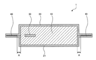
- FIG. 1 is a cross-sectional view showing a schematic configuration of a vacuum heat insulating material 1 according to the present embodiment.
- the dimensional relationship and shape of each component may differ from the actual ones. Specific dimensions and the like of each component should be determined in consideration of the following description.
- the vacuum heat insulating material 1 includes a core material 10 made of a fiber assembly, two outer packaging materials 20, 21 having gas barrier properties and covering both surfaces of the core material 10, and an outer packaging material 20. , 21 and a moisture adsorbent 30 that adsorbs moisture and suppresses deterioration over time of the core material 10 and the like.
- the internal spaces of the outer packaging materials 20 and 21 are sealed under reduced pressure by sealing the opening in a state where the pressure is reduced to a degree of vacuum of about 1 to 3 Pa. Sealing of the opening is performed by welding the peripheral portions of the outer packaging materials 20 and 21 by heat sealing or the like to form the welding seal portion 40.
- the vacuum heat insulating material 1 has a substantially rectangular flat plate shape as a whole.
- the outer packaging materials 20 and 21 are outer packaging materials used for existing vacuum heat insulating materials, and are laminated films having a multilayer structure.
- This multilayer structure has, for example, a structure in which a polyethylene layer, an aluminum vapor deposition layer, a polyethylene terephthalate layer, and an outermost stretched nylon layer are laminated in order from the inner side (core material 10 side).
- the configuration of the outer packaging materials 20 and 21 is not limited to the above configuration, and may include an alumina vapor deposition layer, an ethylene-vinyl alcohol layer, and a polypropylene layer.
- the outer packaging materials 20 and 21 are not particularly limited in configuration as long as they have gas barrier properties.
- the moisture adsorbent 30 is made of, for example, calcium oxide (CaO) inserted in a bag having good air permeability.
- the water adsorbent 30 is not limited to CaO alone, and a water adsorbent such as zeolite can be used.
- the core material 10 has a configuration in which fiber aggregates such as glass wool are laminated.
- the core material 10 has a thickness of 10 mm or more (for example, 50 mm or less) under atmospheric pressure in the vacuum heat insulating material 1 after completion. That is, the vacuum heat insulating material 1 has a thickness of 10 mm or more as a whole under atmospheric pressure. If the core material 10 is taken out from the outer packaging materials 20 and 21, the thickness of the core material 10 under atmospheric pressure is 10 times or more (for example, 20 times or less) of the thickness of the vacuum heat insulating material 1.
- the fiber aggregate is generally manufactured by a centrifugal method if it is glass wool, and is manufactured by a spunbond method if it is a resin fiber, but the manufacturing method of the fiber aggregate is not particularly limited. .
- the fiber assembly constituting the core material 10 is directly covered with the outer packaging material 20 without using an inner packaging material such as an inner bag. That is, in the vacuum heat insulating material 1, the fiber assembly constituting the core material 10 is in direct contact with the inner surface of the outer packaging material 20. Further, the core material 10 does not contain a binder that binds the fiber assembly.
- the welding seal portion 40 is formed on at least three sides (for example, four sides) of the peripheral portions (ear portions) of the outer packaging materials 20 and 21.
- the welding seal portion 40 is formed without any breaks over the entire circumference of the peripheral edge portions of the outer packaging materials 20 and 21.
- the distance A between the welding seal part 40 and the core material 10 is 5 mm or less (for example, 1 mm or more) on at least two opposite sides of the peripheral parts of the outer packaging materials 20 and 21.
- the welding seal portion 40 is fixed along the shape of the core material 10.
- 2 to 4 are diagrams showing the manufacturing process of the vacuum heat insulating material 1.
- 2 to 4 also show the configuration of the processing apparatus 50 used in the manufacturing process.
- the processing apparatus 50 includes a compression mechanism 51 and welding mechanisms 52a and 52b.
- the compression mechanism 51 integrally compresses and compresses the core material 10 and the outer packaging materials 20 and 21 covering the core material 10.
- the welding mechanisms 52a and 52b are configured to place the welding seal portion 40 on two opposite sides of the peripheral portions of the outer packaging materials 20 and 21 in a state where the core material 10 and the outer packaging materials 20 and 21 are compressed by the compression mechanism 51. To form.
- the welding mechanisms 52a and 52b are disposed on both sides of the compression mechanism 51. Further, the welding mechanisms 52a and 52b are provided in the compression mechanism 51 so that the welding seal portion 40 can be formed in the vicinity of the core material 10 in a state where the core material 10 and the outer packaging materials 20 and 21 are compressed by the compression mechanism 51. Proximity is provided. For example, the welding mechanisms 52a and 52b can form the welding seal part 40 in which the distance A between the welding seal part 40 and the core material 10 is 5 mm or less.
- the core material 10 is processed into a necessary width and length as the vacuum heat insulating material 1, and both surfaces (upper surface and lower surface) of the core material 10 are 2. It arrange
- the thickness T1 of the core material 10 at this time is 10 times or more compared with the thickness of the vacuum heat insulating material 1 after completion (or the thickness of the core material 10).
- the core member 10 and the outer packaging materials 20, 21 are mechanically compressed and compressed integrally from both outer surfaces of the outer packaging materials 20, 21 by the compression mechanism 51 (pressure compression process).
- the pressure compression process is performed in an atmospheric pressure atmosphere.
- the pressure at the time of compression is preferably 0.10 MPa or more equivalent to atmospheric pressure, and more preferably 0.17 MPa or more.
- the thickness T2 of the core material 10 in the compressed state is 1/10 or less (for example, 1/20 or more) of the thickness T1 of the core material 10 before compression under atmospheric pressure.
- the integral thickness of the core material 10 and the outer packaging materials 20 and 21 in the compressed state is substantially the same as the thickness of the vacuum heat insulating material 1 after completion.
- the peripheral portions of the outer packaging materials 20 and 21 are formed by the welding mechanism 52 a.
- sticker part 40 is formed in one side of them (welding seal
- the welding seal portion 40 is formed on the other one side of the peripheral portions of the outer packaging materials 20 and 21 opposite to the one side by the welding mechanism 52b.
- These welding seal portions 40 may be formed at the same time.
- these welding seal parts 40 are formed so that the distance A with respect to the core material 10 may be 5 mm or less (for example, 1 mm or more), for example.
- the welding seal portion forming step is performed in an atmospheric pressure atmosphere.
- the welding seal portions 40 By forming the welding seal portions 40 on the two opposite sides, the core material 10 and the outer packaging materials 20 and 21 are integrated, and the compressed state of the core material 10 is maintained even when the pressure applied by the compression mechanism 51 is released. .
- the welding seal portion 40 may be formed on three or more sides of the outer packaging materials 20, 21 as long as an opening is secured in a part of the peripheral portion of the outer packaging materials 20, 21.
- the pressurization by the compression mechanism 51 is released, and the integrated core material 10 and outer packaging materials 20 and 21 are taken out from the processing apparatus 50.
- moisture content from the core material 10 and the outer packaging materials 20 and 21 is performed.
- a drying process is performed on the conditions which can remove the water
- the conditions of a drying process are not limited to this, What is necessary is just the conditions which can remove the water
- moisture adsorbent 30 is inserted into the internal space of the outer packaging materials 20 and 21 (moisture adsorbent insertion step).
- the moisture adsorbent insertion step is not limited to being performed after the drying step, and may be performed before the drying step or before the pressure compression step.
- the inside of the outer packaging materials 20 and 21 is depressurized to a degree of vacuum of about 1 to 3 Pa, and a heat seal or the like is applied to the opening (for example, sides other than the two sides where the welded seal portion 40 is already formed) in the depressurized state
- a heat seal or the like is applied to the opening (for example, sides other than the two sides where the welded seal portion 40 is already formed) in the depressurized state
- the welding seal portion 40 is formed, and the inside of the outer packaging materials 20 and 21 is sealed under reduced pressure (a reduced pressure sealing step).
- the welding seal portion 40 formed in the vacuum sealing step may also be formed so that the distance from the core material 10 is 5 mm or less.
- the vacuum heat insulating material 1 is obtained through the above steps.
- the core material 10 and the outer packaging materials 20 and 21 are integrally compressed by an external force, and the thickness of the core material 10 is 1 before compression.
- the welded seal portion 40 is formed on at least two opposing sides of the peripheral portions of the outer packaging materials 20 and 21 in the compressed state.
- the distance A of the welding seal part 40 and the core material 10 can be shortened in at least two opposing sides of the peripheral parts of the outer packaging materials 20 and 21.
- the distance A can be 5 mm or less.
- edge part in which the core material 10 does not exist in the peripheral part of the vacuum heat insulating material 1 can be reduced, the material cost of the outer packaging materials 20 and 21 can be reduced. Moreover, since the width
- the vacuum heat insulating material 1 of the present embodiment is set to, for example, 5 mm or less on at least two opposing sides of the peripheral portions of the outer packaging materials 20 and 21. it can.
- edge part in which the core material 10 does not exist can be reduced rather than a general vacuum heat insulating material, the usage-amount of the outer packaging materials 20 and 21 can be reduced, and the outer packaging materials 20 and 21 can be reduced. Material costs can be reduced. Therefore, according to this Embodiment, the vacuum heat insulating material 1 can be obtained cheaply.
- the distance A between the welded seal portion 40 and the core material 10 can be shortened (for example, the distance A can be 5 mm or less) on at least two opposite sides.
- the action of the core material 10 trying to expand due to the restoring force can be suppressed by the outer packaging materials 20 and 21 and the welding seal portion 40.
- the integral thickness of the core material 10 and the outer packaging materials 20, 21 and the thickness of the vacuum heat insulating material 1 after completion (after pressure reduction sealing) Can be substantially matched.
- the core material is preliminarily sealed under reduced pressure using a method in which the core material is heated and pressed into a board shape in advance, a method in which the fiber assembly is bound using a binder, an inner packaging material, or the like. Even without using a method or the like, the volume change of the core material 10 before and after sealing the inside of the outer packaging materials 20 and 21 under reduced pressure can be reduced. Therefore, it is possible to suppress an increase in power costs for heating the core material and material costs for the binder and the encapsulating material. Thereby, according to this Embodiment, the vacuum heat insulating material 1 can be obtained cheaply.
- FIG. 5 is a cross-sectional view showing a schematic configuration of the vacuum heat insulating material 2 according to the present embodiment.
- symbol is attached
- the width B on one side of the welding seal portion 40 (for example, all the welding seal portions 40 formed on the four sides of the peripheral portions of the outer packaging materials 20 and 21) is 50 mm or more ( For example, it is characterized in that it is 100 mm or less. That is, in the present embodiment, the width B of the welding seal portion 40 is set to 50 mm or more in the welding seal portion forming step or the vacuum sealing step in the manufacturing process of the vacuum heat insulating material 2.
- the structure of the other part of the vacuum heat insulating material 2 is the same as that of the vacuum heat insulating material 1 of the first embodiment.
- the fiber length of a general fiber assembly used as the core material 10 is about 20 mm.
- the width B of the welding seal part 40 can be made sufficiently larger than the fiber length of the core material 10 by setting the width B of the welding seal part 40 to 50 mm or more. For this reason, when forming the welding seal portion 40 using the welding mechanism 52b or the like, even if the fibers of the core material 10 are bitten into the welding seal portion 40, vacuum leakage occurs from the biting position of the fibers. Can be prevented. Therefore, according to the present embodiment, in addition to obtaining the same effect as in the first embodiment, it is possible to obtain the vacuum heat insulating material 2 with higher reliability.
- FIG. 6 is a cross-sectional view showing a schematic configuration of the heat insulating box 3 according to the present embodiment.
- a heat insulating box of a refrigerator will be described as an example.
- the heat insulating box 3 has an inner box 60 and an outer box 61.
- the vacuum heat insulating material 1 (or the vacuum heat insulating material 2) is disposed.
- the vacuum heat insulating material 1 is disposed in close contact with the outer wall surface of the inner box 60, for example.
- a portion other than the vacuum heat insulating material 1 is filled with a urethane foam heat insulating material 62. Since the other part of the heat insulation box 3 is the same as that of a general refrigerator heat insulation box, its illustration and description are omitted.
- the heat insulating box 3 can be obtained at low cost. Moreover, in this Embodiment, since the vacuum heat insulating material 1 which has high heat insulation performance compared with the urethane foam heat insulating material 62 grade
- the vacuum heat insulating material 1 is in close contact with the outer wall surface of the inner box 60, but the vacuum heat insulating material 1 may be in close contact with the inner wall surface of the outer box 61. Moreover, the vacuum heat insulating material 1 may be arrange
- Embodiment 3 the configuration in which the vacuum heat insulating materials 1 and 2 are used in the heat insulating box 3 of the refrigerator provided with the cold heat source is taken as an example, but the present invention is not limited thereto.
- the vacuum heat insulating materials 1 and 2 can also be used for a heat insulating box with a heat source or a heat insulating box without a cold heat source and a heat source (for example, a cooler box).
- the vacuum heat insulating materials 1 and 2 can be used not only as a heat insulating box but also as a heat insulating member for a cooling device or a heating device such as an air conditioner, a vehicle air conditioner, or a water heater. Moreover, the vacuum heat insulating materials 1 and 2 are used not only for a box having a predetermined shape like a heat insulating box, but also for a heat insulating bag having a deformable outer bag and an inner bag, and other heat insulating containers. Can do.
Abstract
Description
本発明の実施の形態1に係る真空断熱材及びその製造方法について説明する。図1は、本実施の形態に係る真空断熱材1の概略構成を示す断面図である。なお、図1を含む以下の図面では、各構成部材の寸法の関係や形状等が実際のものとは異なる場合がある。各構成部材の具体的な寸法等は、以下の説明を参酌した上で判断すべきものである。
本発明の実施の形態2に係る真空断熱材及びその製造方法について説明する。図5は、本実施の形態に係る真空断熱材2の概略構成を示す断面図である。なお、実施の形態1と同一の機能及び作用を有する構成要素については、同一の符号を付してその説明を省略する。
本発明の実施の形態3に係る断熱箱について説明する。上記の実施の形態1及び2では真空断熱材及びその製造方法について説明したが、上記実施の形態1又は2に係る真空断熱材1又は2を断熱箱に使用することで、安価でかつ断熱性能の高い断熱箱を得ることができる。図6は、本実施の形態に係る断熱箱3の概略構成を示す断面図である。本実施の形態では、冷蔵庫の断熱箱を例に挙げて説明する。
本発明は、上記実施の形態に限らず種々の変形が可能である。
例えば、上記実施の形態3では、冷熱源を備える冷蔵庫の断熱箱3に真空断熱材1、2が用いられた構成を例に挙げたが、本発明はこれに限られない。真空断熱材1、2は、温熱源を備える保温庫の断熱箱や、冷熱源及び温熱源を備えない断熱箱(例えば、クーラーボックス等)に用いることもできる。
Claims (8)
- 繊維集合体からなる芯材を外包材で被覆し、
前記外包材の内部を減圧する前に、前記芯材及び前記外包材を外力で一体に圧縮して、前記芯材の厚みが圧縮前の1/10以下となる圧縮状態とし、
前記圧縮状態において、前記外包材の周縁部のうち少なくとも相対する2辺に溶着シール部を形成し、
前記溶着シール部を形成した後に、前記外包材の内部を減圧して密封する真空断熱材の製造方法。 - 前記溶着シール部は、前記芯材との距離が5mm以下となるように形成する請求項1に記載の真空断熱材の製造方法。
- 請求項1又は請求項2に記載の真空断熱材の製造方法により製造された真空断熱材を備える断熱箱。
- 繊維集合体からなる芯材と、前記芯材を被覆する外包材とを備え、前記外包材の内部が減圧密封され、全体として10mm以上の断熱材厚みを有する真空断熱材であって、
前記外包材は、周縁部に溶着シール部を有しており、
前記外包材の周縁部のうち少なくとも相対する2辺において、前記溶着シール部と前記芯材との距離が5mm以下であり、
前記溶着シール部が、前記芯材形状に沿って固定されており、
前記外包材の内部から前記芯材を取り出した場合における大気圧下での前記芯材の厚みは、前記断熱材厚みの10倍以上である真空断熱材。 - 前記繊維集合体はグラスウールである請求項4に記載の真空断熱材。
- 前記芯材は、前記繊維集合体を結着させる結合剤を含まない請求項4又は請求項5に記載の真空断熱材。
- 前記溶着シール部の幅が50mm以上である請求項4~請求項6のいずれか一項に記載の真空断熱材。
- 請求項4~請求項7のいずれか一項に記載の真空断熱材を備える断熱箱。
Priority Applications (7)
| Application Number | Priority Date | Filing Date | Title |
|---|---|---|---|
| SG11201510107QA SG11201510107QA (en) | 2013-09-06 | 2014-08-01 | Vacuum thermal insulator, thermal insulation box, and method of manufacturing vacuum thermal insulator |
| AU2014316348A AU2014316348B2 (en) | 2013-09-06 | 2014-08-01 | Vacuum thermal insulator, thermal insulation box, and method of manufacturing vacuum thermal insulator |
| KR1020167001074A KR20160020535A (ko) | 2013-09-06 | 2014-08-01 | 진공 단열재, 단열 상자 및 진공 단열재의 제조 방법 |
| TW103127568A TWI607883B (zh) | 2013-09-06 | 2014-08-12 | Vacuum insulation material, heat insulation box, and vacuum insulation material manufacturing method |
| CN201410436514.1A CN104455935B (zh) | 2013-09-06 | 2014-08-29 | 真空隔热材料、隔热箱以及真空隔热材料的制造方法 |
| CN201420496654.3U CN204114473U (zh) | 2013-09-06 | 2014-08-29 | 真空隔热材料以及隔热箱 |
| HK15107611.7A HK1207146A1 (en) | 2013-09-06 | 2015-08-07 | Vacuum insulation material, insulated box, and method for producing vacuum insulation material |
Applications Claiming Priority (2)
| Application Number | Priority Date | Filing Date | Title |
|---|---|---|---|
| JP2013-184804 | 2013-09-06 | ||
| JP2013184804A JP6132715B2 (ja) | 2013-09-06 | 2013-09-06 | 真空断熱材の製造方法及び断熱箱 |
Publications (1)
| Publication Number | Publication Date |
|---|---|
| WO2015033717A1 true WO2015033717A1 (ja) | 2015-03-12 |
Family
ID=52628202
Family Applications (1)
| Application Number | Title | Priority Date | Filing Date |
|---|---|---|---|
| PCT/JP2014/070401 WO2015033717A1 (ja) | 2013-09-06 | 2014-08-01 | 真空断熱材、断熱箱、及び真空断熱材の製造方法 |
Country Status (8)
| Country | Link |
|---|---|
| JP (1) | JP6132715B2 (ja) |
| KR (1) | KR20160020535A (ja) |
| CN (2) | CN204114473U (ja) |
| AU (1) | AU2014316348B2 (ja) |
| HK (1) | HK1207146A1 (ja) |
| SG (1) | SG11201510107QA (ja) |
| TW (1) | TWI607883B (ja) |
| WO (1) | WO2015033717A1 (ja) |
Cited By (1)
| Publication number | Priority date | Publication date | Assignee | Title |
|---|---|---|---|---|
| EP3327387A4 (en) * | 2015-10-26 | 2018-10-10 | Samsung Electronics Co., Ltd. | Vacuum insulation material, vacuum insulation material manufacturing method, and refrigerator including vacuum insulation material |
Families Citing this family (9)
| Publication number | Priority date | Publication date | Assignee | Title |
|---|---|---|---|---|
| RU2691890C1 (ru) * | 2015-08-26 | 2019-06-18 | Мицубиси Электрик Корпорейшн | Холодильник (варианты) |
| DE102015122756A1 (de) * | 2015-12-23 | 2017-06-29 | Saint-Gobain Isover | Verfahren zur Herstellung von Vakuum-Isolations-Paneelen |
| KR101845899B1 (ko) * | 2016-02-01 | 2018-04-05 | 주식회사 케이씨씨 | 진공단열재 제조방법 및 제조장치 |
| US11549635B2 (en) * | 2016-06-30 | 2023-01-10 | Intelligent Energy Limited | Thermal enclosure |
| US10593967B2 (en) | 2016-06-30 | 2020-03-17 | Honeywell International Inc. | Modulated thermal conductance thermal enclosure |
| CN106764253A (zh) * | 2016-11-28 | 2017-05-31 | 王郁倩 | 一种无折边真空绝热材料及制备方法 |
| AU2017424996B2 (en) * | 2017-07-25 | 2021-03-11 | Mitsubishi Electric Corporation | Vacuum insulation material, heat insulation box, and method for producing vacuum insulation material |
| JP2020122631A (ja) * | 2019-01-31 | 2020-08-13 | 東芝ライフスタイル株式会社 | 冷蔵庫、及び真空断熱パネル |
| KR102211452B1 (ko) * | 2020-04-01 | 2021-02-02 | 전순복 | 진공단열재 제조 장치와 제조 방법 및 상기 장치와 방법에 의하여 만들어진 진공단열재 |
Citations (4)
| Publication number | Priority date | Publication date | Assignee | Title |
|---|---|---|---|---|
| JP2006112641A (ja) * | 2004-10-12 | 2006-04-27 | Hitachi Home & Life Solutions Inc | 冷蔵庫 |
| JP2006177497A (ja) * | 2004-12-24 | 2006-07-06 | Mitsubishi Electric Corp | 真空断熱材、及び、その製造方法、並びに、その真空断熱材を用いた断熱箱体 |
| JP2007092776A (ja) * | 2005-09-27 | 2007-04-12 | Toshiba Home Technology Corp | 断熱材およびその製造方法 |
| JP2008249003A (ja) * | 2007-03-30 | 2008-10-16 | Hitachi Appliances Inc | 真空断熱パネル及びそれを備えた機器 |
Family Cites Families (10)
| Publication number | Priority date | Publication date | Assignee | Title |
|---|---|---|---|---|
| JPH09138058A (ja) * | 1995-11-14 | 1997-05-27 | Sanyo Electric Co Ltd | 真空断熱材 |
| JP2005220945A (ja) * | 2004-02-03 | 2005-08-18 | Mitsubishi Fuso Truck & Bus Corp | エンジンのベルト張力調整装置 |
| JP3580315B1 (ja) * | 2004-02-04 | 2004-10-20 | 松下電器産業株式会社 | 真空断熱材とその製造方法、真空断熱材を具備する保温保冷機器、および断熱ボード |
| JP2007009928A (ja) * | 2005-06-28 | 2007-01-18 | Hitachi Appliances Inc | 真空断熱材及びその製造方法並びに冷蔵庫 |
| KR20070054040A (ko) * | 2005-11-22 | 2007-05-28 | 엘지전자 주식회사 | 진공 단열재 및 이를 적용한 냉장고의 단열 구조 |
| JP4861715B2 (ja) * | 2006-02-06 | 2012-01-25 | 日立アプライアンス株式会社 | 真空断熱材の製造方法 |
| JP4774320B2 (ja) * | 2006-03-30 | 2011-09-14 | 日立アプライアンス株式会社 | 真空断熱材及びその製造方法 |
| KR101280776B1 (ko) * | 2010-09-14 | 2013-07-05 | 히타치 어플라이언스 가부시키가이샤 | 진공 단열재 및 이것을 이용한 냉장고 |
| US10032210B2 (en) * | 2011-02-08 | 2018-07-24 | Cfph, Llc | Apparatus, article of manufacture and methods for purchasing arbitrage |
| DE102013104712A1 (de) * | 2013-05-07 | 2014-11-13 | Saint-Gobain Isover | Verfahren zur Herstellung von Vakuum-Isolations-Paneelen |
-
2013
- 2013-09-06 JP JP2013184804A patent/JP6132715B2/ja active Active
-
2014
- 2014-08-01 AU AU2014316348A patent/AU2014316348B2/en active Active
- 2014-08-01 KR KR1020167001074A patent/KR20160020535A/ko active Search and Examination
- 2014-08-01 SG SG11201510107QA patent/SG11201510107QA/en unknown
- 2014-08-01 WO PCT/JP2014/070401 patent/WO2015033717A1/ja active Application Filing
- 2014-08-12 TW TW103127568A patent/TWI607883B/zh active
- 2014-08-29 CN CN201420496654.3U patent/CN204114473U/zh active Active
- 2014-08-29 CN CN201410436514.1A patent/CN104455935B/zh active Active
-
2015
- 2015-08-07 HK HK15107611.7A patent/HK1207146A1/xx unknown
Patent Citations (4)
| Publication number | Priority date | Publication date | Assignee | Title |
|---|---|---|---|---|
| JP2006112641A (ja) * | 2004-10-12 | 2006-04-27 | Hitachi Home & Life Solutions Inc | 冷蔵庫 |
| JP2006177497A (ja) * | 2004-12-24 | 2006-07-06 | Mitsubishi Electric Corp | 真空断熱材、及び、その製造方法、並びに、その真空断熱材を用いた断熱箱体 |
| JP2007092776A (ja) * | 2005-09-27 | 2007-04-12 | Toshiba Home Technology Corp | 断熱材およびその製造方法 |
| JP2008249003A (ja) * | 2007-03-30 | 2008-10-16 | Hitachi Appliances Inc | 真空断熱パネル及びそれを備えた機器 |
Cited By (1)
| Publication number | Priority date | Publication date | Assignee | Title |
|---|---|---|---|---|
| EP3327387A4 (en) * | 2015-10-26 | 2018-10-10 | Samsung Electronics Co., Ltd. | Vacuum insulation material, vacuum insulation material manufacturing method, and refrigerator including vacuum insulation material |
Also Published As
| Publication number | Publication date |
|---|---|
| CN104455935B (zh) | 2016-10-05 |
| HK1207146A1 (en) | 2016-01-22 |
| CN104455935A (zh) | 2015-03-25 |
| CN204114473U (zh) | 2015-01-21 |
| TW201524784A (zh) | 2015-07-01 |
| AU2014316348A1 (en) | 2016-01-07 |
| SG11201510107QA (en) | 2016-04-28 |
| KR20160020535A (ko) | 2016-02-23 |
| AU2014316348B2 (en) | 2016-12-01 |
| JP6132715B2 (ja) | 2017-05-24 |
| TWI607883B (zh) | 2017-12-11 |
| JP2015052337A (ja) | 2015-03-19 |
Similar Documents
| Publication | Publication Date | Title |
|---|---|---|
| JP6132715B2 (ja) | 真空断熱材の製造方法及び断熱箱 | |
| KR100823798B1 (ko) | 진공 단열재 및 진공 단열재를 이용한 냉장고 | |
| JP6070269B2 (ja) | 断熱体 | |
| JP6579740B2 (ja) | 真空断熱材の製造方法 | |
| JP2015052337A5 (ja) | ||
| JP2016084833A (ja) | 真空断熱材及び断熱箱 | |
| JP2006226298A (ja) | 真空断熱材およびその製造方法 | |
| JP5646241B2 (ja) | 冷蔵庫 | |
| WO2017029727A1 (ja) | 真空断熱材及び断熱箱 | |
| JP2016017591A (ja) | 真空断熱材の製造方法、及びその製造方法で製造された真空断熱材 | |
| JP6333085B2 (ja) | 繊維集合体の成形方法、並びに、繊維集合体、真空断熱材、及び断熱箱の製造方法 | |
| KR20140112722A (ko) | 진공단열재의 제조방법 | |
| WO2019171566A1 (ja) | 真空断熱材及び断熱箱 | |
| WO2021095391A1 (ja) | 断熱部材の製造方法、断熱部材、該断熱部材を使用する冷熱機器及び該冷熱機器の製造方法 | |
| JP2018200106A (ja) | 断熱体 | |
| JP6489158B2 (ja) | 断熱体 | |
| JP7264912B2 (ja) | 断熱部材およびその製造方法 | |
| JP6775585B2 (ja) | 真空断熱材及び断熱箱 | |
| JP2017003119A (ja) | 断熱体 | |
| JP7129979B2 (ja) | 真空断熱材の製造方法 | |
| JP2011185413A (ja) | 真空断熱材の製造方法 | |
| JP3983783B2 (ja) | 真空断熱材の製造方法 | |
| JP2015175501A (ja) | 真空断熱材及びこれを用いた冷蔵庫 |
Legal Events
| Date | Code | Title | Description |
|---|---|---|---|
| 121 | Ep: the epo has been informed by wipo that ep was designated in this application |
Ref document number: 14842218 Country of ref document: EP Kind code of ref document: A1 |
|
| ENP | Entry into the national phase |
Ref document number: 2014316348 Country of ref document: AU Date of ref document: 20140801 Kind code of ref document: A |
|
| ENP | Entry into the national phase |
Ref document number: 20167001074 Country of ref document: KR Kind code of ref document: A |
|
| NENP | Non-entry into the national phase |
Ref country code: DE |
|
| 122 | Ep: pct application non-entry in european phase |
Ref document number: 14842218 Country of ref document: EP Kind code of ref document: A1 |