WO2015033430A1 - 電動モータ - Google Patents
電動モータ Download PDFInfo
- Publication number
- WO2015033430A1 WO2015033430A1 PCT/JP2013/074024 JP2013074024W WO2015033430A1 WO 2015033430 A1 WO2015033430 A1 WO 2015033430A1 JP 2013074024 W JP2013074024 W JP 2013074024W WO 2015033430 A1 WO2015033430 A1 WO 2015033430A1
- Authority
- WO
- WIPO (PCT)
- Prior art keywords
- electric motor
- control board
- sunroof
- yoke
- reduction mechanism
- Prior art date
- Legal status (The legal status is an assumption and is not a legal conclusion. Google has not performed a legal analysis and makes no representation as to the accuracy of the status listed.)
- Ceased
Links
Images


Classifications
-
- H—ELECTRICITY
- H02—GENERATION; CONVERSION OR DISTRIBUTION OF ELECTRIC POWER
- H02K—DYNAMO-ELECTRIC MACHINES
- H02K11/00—Structural association of dynamo-electric machines with electric components or with devices for shielding, monitoring or protection
- H02K11/40—Structural association with grounding devices
-
- H—ELECTRICITY
- H02—GENERATION; CONVERSION OR DISTRIBUTION OF ELECTRIC POWER
- H02K—DYNAMO-ELECTRIC MACHINES
- H02K11/00—Structural association of dynamo-electric machines with electric components or with devices for shielding, monitoring or protection
- H02K11/01—Structural association of dynamo-electric machines with electric components or with devices for shielding, monitoring or protection for shielding from electromagnetic fields, i.e. structural association with shields
- H02K11/014—Shields associated with stationary parts, e.g. stator cores
- H02K11/0141—Shields associated with casings, enclosures or brackets
-
- H—ELECTRICITY
- H02—GENERATION; CONVERSION OR DISTRIBUTION OF ELECTRIC POWER
- H02K—DYNAMO-ELECTRIC MACHINES
- H02K7/00—Arrangements for handling mechanical energy structurally associated with dynamo-electric machines, e.g. structural association with mechanical driving motors or auxiliary dynamo-electric machines
- H02K7/10—Structural association with clutches, brakes, gears, pulleys or mechanical starters
- H02K7/116—Structural association with clutches, brakes, gears, pulleys or mechanical starters with gears
- H02K7/1163—Structural association with clutches, brakes, gears, pulleys or mechanical starters with gears where at least two gears have non-parallel axes without having orbital motion
- H02K7/1166—Structural association with clutches, brakes, gears, pulleys or mechanical starters with gears where at least two gears have non-parallel axes without having orbital motion comprising worm and worm-wheel
Definitions
- the present invention relates to an electric motor including a yoke that houses a rotating shaft, and a casing that houses a speed reduction mechanism and a substrate.
- an electric motor with a speed reduction mechanism is often used as a drive source for a sunroof device or the like.
- An electric motor used in such a sunroof device includes a yoke that rotatably accommodates an armature shaft (rotating shaft), and a speed reduction mechanism that is connected to the opening end of the yoke and decelerates the rotation of the armature shaft.
- Gear case (casing).
- As the speed reduction mechanism a mechanism including a worm rotated by an armature shaft and a worm wheel having gear teeth meshing with the worm is used, so that a large output can be achieved while being small.
- a control board (substrate) is provided.
- the control board is housed inside the gear case together with the speed reduction mechanism, thereby preventing exposure to rainwater, dust, and the like.
- a gear cover (cover member) is provided between the speed reduction mechanism and the control board, thereby preventing the lubricating oil such as grease applied to the speed reduction mechanism from scattering toward the control board.
- Patent Document 1 As described above, as an electric motor in which a gear cover is provided between a speed reduction mechanism and a control board, for example, a technique described in Patent Document 1 is known.
- the electric motor described in Patent Document 1 forms a gear cover by, for example, pressing a metal steel plate.
- a plurality of mounting claws provided integrally around the gear cover are respectively inserted into a plurality of mounting holes formed in the resin gear case so that the gear cover can be firmly fixed to the gear case without rattling. ing.
- An object of the present invention is to provide an electric motor capable of preventing the external noise reaching the cover member from being reflected by various portions of the substrate and further improving the reliability.
- a yoke that accommodates the rotation shaft, a casing connected to the yoke, a speed reduction mechanism accommodation portion that is provided in the casing and accommodates a reduction mechanism that decelerates the rotation of the rotation shaft,
- a substrate housing portion that is provided in the casing and houses a substrate that controls the rotation of the rotating shaft; and a metal cover member that covers the speed reduction mechanism housing portion, and the cover member includes the deceleration member It is disposed between the mechanism and the substrate and is grounded.
- a metal contact plate having a connection terminal is provided between the yoke and the casing, and the connection terminal is connected to the cover member.
- the cover member includes a mounting claw mounted in a mounting hole provided in the casing, and connects the connection terminal to the mounting claw.
- the metal cover member provided so as to cover the speed reduction mechanism housing portion is disposed between the speed reduction mechanism and the substrate so as to be grounded.
- FIG. 3 is an exploded perspective view of the sunroof motor shown in FIG. 2. It is a perspective view explaining the connection relation of a gear cover and a contact plate. It is the elements on larger scale which expand and show the broken-line circle
- FIG. 1 is an explanatory view showing an outline of a sunroof device provided on the roof of the vehicle
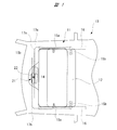
- FIG. 2 is a plan view showing details of the sunroof motor shown in FIG. 1
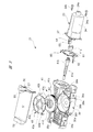
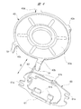
- FIG. 3 is an exploded perspective view of the sunroof motor shown in FIG. 4 is a perspective view for explaining the connection relationship between the gear cover and the contact plate
- FIG. 5 is a partially enlarged view showing the broken-line circle A portion of FIG. 2 in an enlarged manner.
- the sunroof device 11 includes a roof panel (sunroof) 12, and the roof panel 12 opens and closes an opening 14 formed in the roof 13 a of the vehicle 13.
- a pair of shoes 15a and 15b are fixed to both sides of the roof panel 12, respectively, while guide rails 16 extending in the vehicle front-rear direction are fixed to both sides of the opening 14 of the roof 13a.
- the shoes 15a and 15b are guided by the corresponding guide rails 16 so that the roof panel 12 can be moved in the vehicle front-rear direction, that is, can be opened and closed.
- One end of geared drive cables 17a, 17b is connected to each shoe 15b on the vehicle rear side, and the other ends of these drive cables 17a, 17b are respectively routed to the vehicle front side of the opening 14. Yes.
- a sunroof motor 21 as an electric motor is disposed on the front side of the vehicle with respect to the opening 14 and inside the roof 13a between the windshield 13b.
- Each drive cable 17a, 17b is meshed with a drive gear 22 provided in the sunroof motor 21.
- the sunroof motor 21 When the sunroof motor 21 is operated, the drive cables 17a and 17b are driven in opposite directions, whereby the roof panel 12 is pushed and pulled by the drive cables 17a and 17b to open and close.
- the sunroof motor 21 includes a motor main body 23 that is a motor with a brush.
- the yoke 24 forming the motor body 23 is formed into a substantially oval bottomed cylindrical shape by pressing a steel plate or the like, and an armature 25 is rotatably accommodated in the yoke 24. .
- An armature shaft (rotating shaft) 26 is fixed through the rotation center of the armature 25, and the armature shaft 26 is rotatably accommodated inside the yoke 24.
- One end of the armature shaft 26 is supported by a bearing (not shown) provided on the bottom 24 a of the yoke 24, so that the armature 25 is rotatable inside the yoke 24.
- the armature core 27 is fixed to the armature shaft 26, and a plurality of armature coils 28 are wound around the armature core 27.
- a commutator 29 is fixed to the armature shaft 26 adjacent to the armature core 27, and the coil ends of the armature coils 28 are connected to the commutator 29.
- the brush device 31 has a structure in which a plurality of brushes 33 a and 33 b (only two are shown in the drawing) are provided on a brush holder 32 so as to be movable.
- the brushes 33 a and 33 b are in sliding contact with the outer peripheral surface of the commutator 29. It has become.
- a drive current commutated at a predetermined timing via the brushes 33a and 33b and the commutator 29 is supplied to the armature coil 28.
- a gear case 36 as a casing is connected to the open end of the yoke 24 via a pair of fastening screws 34a and 34b.
- the gear case 36 is formed in a substantially bathtub shape from a resin material, and a case cover (not shown) is attached to the gear case 36 via five locking claws 36a. That is, the opening portion of the gear case 36 is closed by the case cover, thereby preventing rainwater, dust, or the like from entering the gear case 36.
- a flange portion 37 is integrally provided so as to protrude outward in the radial direction, and the fastening screws 34a and 34b pass through the flange portion 37.
- a pair of female screw portions (not shown) to which the respective fastening screws 34a and 34b are screwed are provided on the gear case 36 side.
- a reduction mechanism 41 is rotatably accommodated in the gear case 36.
- the speed reduction mechanism 41 includes a worm shaft 41b having a worm 41a formed on the outer peripheral portion thereof, and a worm wheel 41d having gear teeth 41c engaged with the worm 41a formed on the outer peripheral portion thereof.
- the other end of the armature shaft 26 is connected to one end of the worm shaft 41b via a connecting member 41e so as to be integrally rotatable, and the output shaft 42 is connected to the rotation center of the worm wheel 41d so as to be integrally rotatable.
- One end of the output shaft 42 extends to the outside from the bottom of the gear case 36, and the drive gear 22 (see FIG. 1) is fixed to the extended portion.
- the rotation of the armature shaft 26 is transmitted to the speed reduction mechanism 41 and is also decelerated by the speed reduction mechanism 41, and the torque that has been increased in torque is applied from the output shaft 42 to the drive cables 17 a and 17 b via the drive gear 22. It is output.
- a worm wheel housing portion 36b formed in a substantially cylindrical shape is provided inside the gear case 36.
- the worm wheel housing portion 36b constitutes a speed reduction mechanism housing portion in the present invention, and a worm wheel 41d forming the speed reduction mechanism 41 is rotatably housed therein.
- a board housing portion 36c for housing a control board (board) 51 formed in a substantially rectangular shape.
- the substrate housing portion 36 c is provided so as to be aligned with the worm wheel housing portion 36 b in the axial direction of the output shaft 42, the worm wheel housing portion 36 b is disposed on the bottom side of the gear case 36, and the opening side of the gear case 36
- a substrate accommodating portion 36c is disposed on the substrate.
- a gear cover (cover member) 43 is attached to the open end of the worm wheel housing portion 36b, that is, the front side in FIG.
- the gear cover 43 is provided so as to cover the open end of the worm wheel accommodating portion 36b. That is, the gear cover 43 is provided with the worm wheel 41d accommodated in the worm wheel accommodating portion 36b and the control substrate 51 accommodated in the substrate accommodating portion 36c. It is arranged between. Thereby, lubricating oil (not shown) such as grease applied to the speed reduction mechanism 41 is prevented from leaking toward the control board 51 and the like inside the gear case 36.
- the gear cover 43 is formed in a substantially disc shape by pressing a metal thin plate (steel plate or the like).
- the gear cover 43 is formed of a main body 43a and a first mounting claw 43b, a second mounting claw 43c, a third mounting claw 43d, and a fourth mounting claw 43e provided around the main body 43a.
- each of the mounting claws 43b to 43e has a substantially L-shaped cross section by bending and deforming its base portion from the main body portion 43a at a substantially right angle.
- a tapered portion TP is provided at the tip of each of the mounting claws 43b to 43e so that each of the mounting claws 43b to 43e is tapered.
- the root portion of the first mounting claw 43b is directed in the axial direction of the armature shaft 26 (the direction of arrow B in FIG. 4), and thereby the tip portion of the first mounting claw 43b. Can be connected to the tip of the connection terminal 62 of the contact plate 60 described later.
- Each of the mounting claws 43b to 43e is inserted into a first mounting hole 36d, a second mounting hole 36e, a third mounting hole 36f, and a fourth mounting hole 36g that are integrally provided around the worm wheel housing portion 36b of the gear case 36. Just plug in each one, and it will be attached under the condition of retaining.
- the mounting claws 43b to 43e are respectively provided with the tapered portions TP, they can be easily mounted in the mounting holes 36d to 36g.
- a metal contact plate 60 is provided between the yoke 24 and the gear case 36.
- the contact plate 60 is connected to the yoke 24 and the gear case 36 by fastening screws 34a and 34b. Is sandwiched between.
- the contact plate 60 is formed into a predetermined shape by pressing a steel plate made of brass or the like having excellent conductivity, and is sandwiched between the yoke 24 and the gear case 36.
- 61 and a connection terminal 62 that is bent and extended in the vertical direction of the annular main body 61.
- a pair of screw insertion notches 61a is formed in the annular main body 61, and the fastening screws 34a are formed in the screw insertion notches 61a in a state where the sunroof motor 21 (see FIG. 2) is assembled. , 34b are inserted. As a result, the contact plate 60 can be accurately mounted between the yoke 24 and the gear case 36 without being displaced.
- the annular main body 61 is provided with a total of four contact portions 61b, and a total of four contact portions (not shown) on the brush device 31 side are in electrical contact with each contact portion 61b. It is like that. As a result, the brush noise BN (see FIG. 5) generated on the brush device 31 side is transmitted to the contact plate 60.
- connection terminal 62 is directed in the axial direction of the armature shaft 26 (in the direction of arrow B in FIG. 4) in a state where the sunroof motor 21 is assembled. 43b can be connected.
- the distal end portion of the connection terminal 62 is disposed inside the first mounting hole 36 d of the gear case 36 via a terminal insertion hole (not shown) provided in the gear case 36. It is like that.
- both the gear cover 43 and the contact plate 60 are shaded so that the metal gear cover 43 and the metal contact plate 60 can be easily understood.
- control substrate 51 accommodated in the substrate accommodating portion 36c controls the rotation of the armature shaft 26 forming the motor body 23.
- the control board 51 is mounted with a control circuit (not shown) for controlling the drive current supplied to the armature coil 28, that is, the power supply to the brushes 33a and 33b.
- the control circuit includes a rotation sensor (not shown) for detecting the rotation of the armature shaft 26 and the like.
- the brush device 31 is provided with a pair of power terminals 53 and 54 (see FIG. 2), and the control board 51 is provided with a pair of connection pieces 55 and 56 (see FIG. 5). Then, by accommodating and fixing the control board 51 in the board housing portion 36c, the connection pieces 55 and 56 are connected to the power terminals 53 and 54, respectively, and the control board 51 and the brushes 33a and 33b are electrically connected. To be connected to.
- Each power supply terminal 53, 54 of the brush device 31 is formed in a plate shape, the longitudinal direction thereof is directed to the axial direction of the armature shaft 26, and the short side direction (width direction) is the opening direction of the gear case 36. It is directed in a direction perpendicular to the direction. Thereby, each power supply terminal 53 and 54 and each connection piece 55 and 56 are made easy to connect, respectively, and the assembly property of the sunroof motor 21 is improved.
- a ground connection piece 57 (see FIGS. 3 and 5) is provided at a portion facing the connection terminal 62 of the control board 51.
- the ground connection piece 57 is also formed in the same shape as the connection pieces 55 and 56. Therefore, the connection piece for grounding is connected to the connection terminal 62 whose longitudinal direction is directed to the axial direction of the armature shaft 26 and whose short direction (width direction) is directed to the direction orthogonal to the opening direction of the gear case 36. 57 is easily connected.
- a connector portion 58 to which an external connector (not shown) is connected is provided on the side opposite to the grounding connection piece 57 side along the longitudinal direction of the control board 51.
- a power source (not shown) such as a battery mounted on the vehicle 13, a sunroof switch (not shown) provided in the vehicle compartment, and the like are connected to the connector portion 58.
- the ground connection piece 57 is grounded (grounded) to the vehicle body (the roof 13 a and the like) of the vehicle 13 via the control board 51 and the connector portion 58. That is, the gear cover 43 is grounded via the ground connection piece 57, the control board 51, and the connector portion 58.
- connection terminal 62 of the contact plate 60 and the ground connection piece 57 of the control board 51 in order to electrically connect the connection terminal 62 of the contact plate 60 and the ground connection piece 57 of the control board 51, as shown by the two-dot chain line arrow in FIG.
- the brush noise BN transmitted from the 61 side and the external noise ON transmitted to the metal gear cover 43 are transmitted to the ground connection piece 57, respectively.
- the brush noise BN and the external noise ON transmitted to the ground connection piece 57 are, for example, the roof 13a of the vehicle 13 and the like via the control board 51 and the connector portion 58 as shown by a two-dot chain line arrow in FIG. Escaped to the car body).
- FIG. 2 is a mounting leg for fixing the sunroof motor 21 to the inside of the roof 13a (see FIG. 1).
- the mounting leg IL is opposed to sandwich the worm wheel housing portion 36b. Has been placed.
- Each mounting leg IL is fixed to the inside of the roof 13a by a fixing bolt (none of which is shown) via a metal bush, and external noise ON such as static electricity is transmitted to the sunroof motor via each mounting leg IL. 21 is relatively easy to enter.
- a driving current is supplied from the power source to the control board 51 via the connector portion 58, and this driving current is controlled to a predetermined current by the control circuit, so that each connection piece 55, 56, power terminals 53, 54, brushes 33a, 33b and the commutator 29 are supplied to the armature coil 28.
- the metal gear cover 43 provided so as to cover the worm wheel housing portion 36 b is disposed between the worm wheel 41 d and the control board 51. To be grounded. Thereby, even if external noise ON such as static electricity enters the sunroof motor 21 and reaches the gear cover 43, the external noise ON can be quickly released to the outside of the sunroof motor 21. Therefore, the external noise ON is not reflected on the control board 51, so that the malfunction of the control board 51 can be surely prevented, and the reliability of the sunroof motor 21 can be further improved.
- the metal contact plate 60 including the connection terminals 62 is provided between the yoke 24 and the gear case 36, and the connection terminals 62 are connected to the gear cover 43. Therefore, the brush noise BN from the motor body 23 side can be quickly released to the outside of the sunroof motor 21.
- the gear cover 43 includes the mounting claws 43b to 43e mounted in the mounting holes 36d to 36g provided in the gear case 36, and the connection terminal 62 is provided with the first connection terminal 62. Since the attachment claws 43b are connected, the connection terminals 62 can be easily electrically connected to the first attachment claws 43b simply by inserting the attachment claws 43b to 43e into the respective 36d to 36g. .
- the present invention is not limited to the above-described embodiment, and various modifications can be made without departing from the scope of the invention.
- the external noise ON and the brush noise BN transmitted to the contact plate 60 via the ground connection piece 57 and the connector portion 58 of the control board 51 are released to the roof 13a of the vehicle 13.
- a thing (grounded) is shown, the present invention is not limited to this.
- various noises transmitted to the contact plate 60 may be allowed to escape to the vehicle body of the vehicle 13, and various noises are transmitted to the vehicle body of the vehicle 13 through the fastening screws 34 a and 34 b that can contact the contact plate 60. You can also escape.
- the ground connection piece 57 can be eliminated, the structures of the control board 51 and the connector portion 58 can be simplified.
- this invention is applied to the sunroof motor 21 used for the sunroof apparatus 11 of the vehicle 13, it is not restricted to this,
- the slide door apparatus provided in a vehicle, a power window apparatus, etc. It can also be applied to an electric motor used in the above.
- the electric motor is used as a drive source for a sunroof device or the like mounted on a vehicle such as an automobile, and is used to open and close the roof panel by pushing and pulling the drive cable.
Landscapes
- Engineering & Computer Science (AREA)
- Power Engineering (AREA)
- Physics & Mathematics (AREA)
- Electromagnetism (AREA)
- Connection Of Motors, Electrical Generators, Mechanical Devices, And The Like (AREA)
- Power-Operated Mechanisms For Wings (AREA)
Abstract
Description
Claims (3)
- 回転軸を収容するヨークと、
前記ヨークに接続されるケーシングと、
前記ケーシングに設けられ、前記回転軸の回転を減速する減速機構を収容する減速機構収容部と、
前記ケーシングに設けられ、前記回転軸の回転を制御する基板を収容する基板収容部と、
前記減速機構収容部を覆うように設けられる金属製のカバー部材と、
を備え、
前記カバー部材は、前記減速機構と前記基板との間に配置され、接地されている、電動モータ。 - 請求項1記載の電動モータにおいて、
前記ヨークと前記ケーシングとの間に、接続端子を備えた金属製のコンタクトプレートを設け、前記接続端子を前記カバー部材に接続させる、電動モータ。 - 請求項2記載の電動モータにおいて、
前記カバー部材は、前記ケーシングに設けられた装着孔に装着される装着爪を備え、前記接続端子を前記装着爪に接続させる、電動モータ。
Priority Applications (4)
| Application Number | Priority Date | Filing Date | Title |
|---|---|---|---|
| PCT/JP2013/074024 WO2015033430A1 (ja) | 2013-09-06 | 2013-09-06 | 電動モータ |
| US14/650,386 US9847699B2 (en) | 2013-09-06 | 2013-09-06 | Electric motor |
| DE112013006102.3T DE112013006102B4 (de) | 2013-09-06 | 2013-09-06 | Elektromotor |
| CN201380067132.XA CN104969454B (zh) | 2013-09-06 | 2013-09-06 | 电动机 |
Applications Claiming Priority (1)
| Application Number | Priority Date | Filing Date | Title |
|---|---|---|---|
| PCT/JP2013/074024 WO2015033430A1 (ja) | 2013-09-06 | 2013-09-06 | 電動モータ |
Publications (1)
| Publication Number | Publication Date |
|---|---|
| WO2015033430A1 true WO2015033430A1 (ja) | 2015-03-12 |
Family
ID=52627937
Family Applications (1)
| Application Number | Title | Priority Date | Filing Date |
|---|---|---|---|
| PCT/JP2013/074024 Ceased WO2015033430A1 (ja) | 2013-09-06 | 2013-09-06 | 電動モータ |
Country Status (4)
| Country | Link |
|---|---|
| US (1) | US9847699B2 (ja) |
| CN (1) | CN104969454B (ja) |
| DE (1) | DE112013006102B4 (ja) |
| WO (1) | WO2015033430A1 (ja) |
Families Citing this family (3)
| Publication number | Priority date | Publication date | Assignee | Title |
|---|---|---|---|---|
| JP7024320B2 (ja) * | 2016-11-07 | 2022-02-24 | 株式会社デンソー | モータ |
| KR102291071B1 (ko) * | 2020-05-25 | 2021-08-23 | 계양전기 주식회사 | 선루프용 모터 유닛 |
| DE102021108502A1 (de) * | 2021-04-06 | 2022-10-06 | Webasto SE | Elektromotor |
Citations (2)
| Publication number | Priority date | Publication date | Assignee | Title |
|---|---|---|---|---|
| WO2004068679A1 (ja) * | 2003-01-27 | 2004-08-12 | Hitachi, Ltd. | コントローラ付き電動モータユニット |
| JP2010057299A (ja) * | 2008-08-29 | 2010-03-11 | Mitsuba Corp | 電動モータ |
Family Cites Families (12)
| Publication number | Priority date | Publication date | Assignee | Title |
|---|---|---|---|---|
| US5872411A (en) * | 1994-03-07 | 1999-02-16 | Asmo Co., Ltd. | Motor terminal device |
| FR2730204B1 (fr) * | 1995-02-08 | 1997-04-04 | Valeo Systemes Dessuyage | Motoreducteur, notamment pour l'entrainement d'un dispositif d'essuie-glace de vehicule |
| DE19548828A1 (de) | 1995-06-29 | 1997-01-02 | Teves Gmbh Alfred | Gehäuse für ein Getriebe |
| DE10125582A1 (de) | 2001-05-25 | 2002-12-05 | Webasto Vehicle Sys Int Gmbh | Antriebsvorrichtung |
| US20060181166A1 (en) | 2003-01-27 | 2006-08-17 | Hitachi, Ltd., | Electric motor unit with controller |
| JP4099133B2 (ja) * | 2003-10-17 | 2008-06-11 | アスモ株式会社 | ターミナルアッセンブリの製造方法、ターミナルアッセンブリ及び車両用ワイパモータ |
| JP4545428B2 (ja) * | 2003-12-16 | 2010-09-15 | 株式会社ミツバ | 電動モータ |
| JP5006592B2 (ja) * | 2006-07-28 | 2012-08-22 | 株式会社ミツバ | 減速機構付き電動モータ |
| JP2008037131A (ja) * | 2006-08-01 | 2008-02-21 | Nsk Ltd | 電動パワーステアリング装置 |
| JP5213590B2 (ja) * | 2008-08-29 | 2013-06-19 | 株式会社ミツバ | 電動モータ |
| JP2010141969A (ja) | 2008-12-09 | 2010-06-24 | Mitsuba Corp | 減速機構付き電動モータ |
| US10320265B2 (en) * | 2009-07-30 | 2019-06-11 | Mitsuba Corporation | Wiper motor |
-
2013
- 2013-09-06 CN CN201380067132.XA patent/CN104969454B/zh active Active
- 2013-09-06 WO PCT/JP2013/074024 patent/WO2015033430A1/ja not_active Ceased
- 2013-09-06 US US14/650,386 patent/US9847699B2/en active Active
- 2013-09-06 DE DE112013006102.3T patent/DE112013006102B4/de active Active
Patent Citations (2)
| Publication number | Priority date | Publication date | Assignee | Title |
|---|---|---|---|---|
| WO2004068679A1 (ja) * | 2003-01-27 | 2004-08-12 | Hitachi, Ltd. | コントローラ付き電動モータユニット |
| JP2010057299A (ja) * | 2008-08-29 | 2010-03-11 | Mitsuba Corp | 電動モータ |
Also Published As
| Publication number | Publication date |
|---|---|
| US20150326096A1 (en) | 2015-11-12 |
| DE112013006102B4 (de) | 2025-03-27 |
| CN104969454A (zh) | 2015-10-07 |
| CN104969454B (zh) | 2018-09-21 |
| US9847699B2 (en) | 2017-12-19 |
| DE112013006102T5 (de) | 2015-09-10 |
Similar Documents
| Publication | Publication Date | Title |
|---|---|---|
| JP5213590B2 (ja) | 電動モータ | |
| JP5139205B2 (ja) | 電動モータ | |
| JP5006714B2 (ja) | ブラシ付き電動モータ | |
| WO2008026503A1 (fr) | Moteur électrique et dispositif d'ouverture/fermeture d'élément d'ouverture/fermeture pour véhicule l'utilisant | |
| CN101335472A (zh) | 带电刷电动机 | |
| EP1990258A3 (en) | Electric power steering apparatus | |
| WO2015033430A1 (ja) | 電動モータ | |
| JP2009201277A (ja) | 減速機構付き電動モータ | |
| JP5139206B2 (ja) | 電動モータ | |
| US11088590B2 (en) | Connection unit for a wiper motor and wiper motor | |
| CN103098347B (zh) | 电动机、带减速器的电动机、以及活动车顶驱动装置 | |
| JP5097649B2 (ja) | 電動モータ及びサンルーフモータ | |
| JP6334966B2 (ja) | 電動モータ装置、ワイパ駆動用電動モータ装置 | |
| JP2023146201A (ja) | モータ装置 | |
| US9496764B2 (en) | Brush holder for an electric motor, and gear mechanism drive unit having a brush holder | |
| JP2009011076A (ja) | 減速機付き電動モータおよびその製造方法 | |
| JP4980741B2 (ja) | 車両用自動開閉装置 | |
| JP2008184876A (ja) | 車両用自動開閉装置 | |
| JP5075766B2 (ja) | 電動モータ | |
| JP5216487B2 (ja) | 電動モータ | |
| JP5164747B2 (ja) | 電動モータ | |
| JP2008184877A (ja) | 車両用自動開閉装置 | |
| JP5602406B2 (ja) | 車両用自動開閉装置 | |
| JP2011074658A (ja) | 車両用自動開閉装置 | |
| JP4417803B2 (ja) | モータ |
Legal Events
| Date | Code | Title | Description |
|---|---|---|---|
| 121 | Ep: the epo has been informed by wipo that ep was designated in this application |
Ref document number: 13892992 Country of ref document: EP Kind code of ref document: A1 |
|
| WWE | Wipo information: entry into national phase |
Ref document number: 14650386 Country of ref document: US |
|
| WWE | Wipo information: entry into national phase |
Ref document number: 112013006102 Country of ref document: DE Ref document number: 1120130061023 Country of ref document: DE |
|
| 122 | Ep: pct application non-entry in european phase |
Ref document number: 13892992 Country of ref document: EP Kind code of ref document: A1 |
|
| NENP | Non-entry into the national phase |
Ref country code: JP |
|
| WWG | Wipo information: grant in national office |
Ref document number: 112013006102 Country of ref document: DE |