WO2015030246A1 - 眼鏡レンズ - Google Patents
眼鏡レンズ Download PDFInfo
- Publication number
- WO2015030246A1 WO2015030246A1 PCT/JP2014/072964 JP2014072964W WO2015030246A1 WO 2015030246 A1 WO2015030246 A1 WO 2015030246A1 JP 2014072964 W JP2014072964 W JP 2014072964W WO 2015030246 A1 WO2015030246 A1 WO 2015030246A1
- Authority
- WO
- WIPO (PCT)
- Prior art keywords
- reflectance
- region
- lens
- light
- coating
- Prior art date
- Legal status (The legal status is an assumption and is not a legal conclusion. Google has not performed a legal analysis and makes no representation as to the accuracy of the status listed.)
- Ceased
Links
Images


Classifications
-
- G—PHYSICS
- G02—OPTICS
- G02C—SPECTACLES; SUNGLASSES OR GOGGLES INSOFAR AS THEY HAVE THE SAME FEATURES AS SPECTACLES; CONTACT LENSES
- G02C7/00—Optical parts
- G02C7/10—Filters, e.g. for facilitating adaptation of the eyes to the dark; Sunglasses
- G02C7/105—Filters, e.g. for facilitating adaptation of the eyes to the dark; Sunglasses having inhomogeneously distributed colouring
-
- C—CHEMISTRY; METALLURGY
- C23—COATING METALLIC MATERIAL; COATING MATERIAL WITH METALLIC MATERIAL; CHEMICAL SURFACE TREATMENT; DIFFUSION TREATMENT OF METALLIC MATERIAL; COATING BY VACUUM EVAPORATION, BY SPUTTERING, BY ION IMPLANTATION OR BY CHEMICAL VAPOUR DEPOSITION, IN GENERAL; INHIBITING CORROSION OF METALLIC MATERIAL OR INCRUSTATION IN GENERAL
- C23C—COATING METALLIC MATERIAL; COATING MATERIAL WITH METALLIC MATERIAL; SURFACE TREATMENT OF METALLIC MATERIAL BY DIFFUSION INTO THE SURFACE, BY CHEMICAL CONVERSION OR SUBSTITUTION; COATING BY VACUUM EVAPORATION, BY SPUTTERING, BY ION IMPLANTATION OR BY CHEMICAL VAPOUR DEPOSITION, IN GENERAL
- C23C14/00—Coating by vacuum evaporation, by sputtering or by ion implantation of the coating forming material
- C23C14/04—Coating on selected surface areas, e.g. using masks
- C23C14/042—Coating on selected surface areas, e.g. using masks using masks
- C23C14/044—Coating on selected surface areas, e.g. using masks using masks using masks to redistribute rather than totally prevent coating, e.g. producing thickness gradient
-
- G—PHYSICS
- G02—OPTICS
- G02B—OPTICAL ELEMENTS, SYSTEMS OR APPARATUS
- G02B1/00—Optical elements characterised by the material of which they are made; Optical coatings for optical elements
- G02B1/10—Optical coatings produced by application to, or surface treatment of, optical elements
- G02B1/11—Anti-reflection coatings
- G02B1/113—Anti-reflection coatings using inorganic layer materials only
- G02B1/115—Multilayers
-
- G—PHYSICS
- G02—OPTICS
- G02B—OPTICAL ELEMENTS, SYSTEMS OR APPARATUS
- G02B5/00—Optical elements other than lenses
- G02B5/20—Filters
- G02B5/26—Reflecting filters
-
- G—PHYSICS
- G02—OPTICS
- G02B—OPTICAL ELEMENTS, SYSTEMS OR APPARATUS
- G02B5/00—Optical elements other than lenses
- G02B5/20—Filters
- G02B5/28—Interference filters
- G02B5/285—Interference filters comprising deposited thin solid films
-
- G—PHYSICS
- G02—OPTICS
- G02C—SPECTACLES; SUNGLASSES OR GOGGLES INSOFAR AS THEY HAVE THE SAME FEATURES AS SPECTACLES; CONTACT LENSES
- G02C7/00—Optical parts
- G02C7/10—Filters, e.g. for facilitating adaptation of the eyes to the dark; Sunglasses
- G02C7/104—Filters, e.g. for facilitating adaptation of the eyes to the dark; Sunglasses having spectral characteristics for purposes other than sun-protection
-
- G—PHYSICS
- G02—OPTICS
- G02C—SPECTACLES; SUNGLASSES OR GOGGLES INSOFAR AS THEY HAVE THE SAME FEATURES AS SPECTACLES; CONTACT LENSES
- G02C7/00—Optical parts
- G02C7/10—Filters, e.g. for facilitating adaptation of the eyes to the dark; Sunglasses
- G02C7/107—Interference colour filters
-
- G—PHYSICS
- G02—OPTICS
- G02B—OPTICAL ELEMENTS, SYSTEMS OR APPARATUS
- G02B5/00—Optical elements other than lenses
- G02B5/02—Diffusing elements; Afocal elements
- G02B5/0205—Diffusing elements; Afocal elements characterised by the diffusing properties
- G02B5/0263—Diffusing elements; Afocal elements characterised by the diffusing properties with positional variation of the diffusing properties, e.g. gradient or patterned diffuser
-
- G—PHYSICS
- G02—OPTICS
- G02C—SPECTACLES; SUNGLASSES OR GOGGLES INSOFAR AS THEY HAVE THE SAME FEATURES AS SPECTACLES; CONTACT LENSES
- G02C2202/00—Generic optical aspects applicable to one or more of the subgroups of G02C7/00
- G02C2202/16—Laminated or compound lenses
-
- G—PHYSICS
- G02—OPTICS
- G02C—SPECTACLES; SUNGLASSES OR GOGGLES INSOFAR AS THEY HAVE THE SAME FEATURES AS SPECTACLES; CONTACT LENSES
- G02C7/00—Optical parts
- G02C7/02—Lenses; Lens systems ; Methods of designing lenses
- G02C7/06—Lenses; Lens systems ; Methods of designing lenses bifocal; multifocal ; progressive
- G02C7/061—Spectacle lenses with progressively varying focal power
Definitions
- the present invention relates to a spectacle lens, and in particular, relates to a spectacle lens having a coating that reflects light in a specific wavelength range and having a good wearing feeling.
- a spectacle lens is manufactured by forming a functional film on a lens substrate for imparting desired performance.
- a functional film a mirror coat (see Patent Document 1) that has high reflectivity for visible light and enhances the fashionability by giving a mirror-like gloss to the lens surface, the eye of a spectacle wearer UV reflection film (see Patent Document 2) for reducing the amount of ultraviolet light incident on the light, and has a short wavelength light reflection performance called blue light having a wavelength of about 400 to 500 nm emitted from a monitor screen of a digital device
- Patent Document 3 a multilayer film
- a film that exhibits the property of reflecting light in a specific wavelength range is referred to as a reflective film.
- the reflective film may be provided only on either the object side or the eyeball side of the spectacle lens, but may also be provided on both sides.
- a spectacle lens having a reflective film on both sides has a strong tendency for a wearer to feel dazzling, and improvement in wearing feeling is required.
- an object of the present invention is to provide a spectacle lens having a coating (reflection film) having a property of reflecting light in a specific wavelength region on both surfaces and having a good wearing feeling.
- the above purpose is Having a film showing the property of reflecting light in a specific wavelength range on both the object-side surface and the eyeball-side surface of the lens substrate; and The reflectance of the coating on one or both surfaces from the lower part to the upper part during wearing, or from the upper part to the lower part during wearing.
- the spectacle lens at least one of the reflection films on both surfaces of the lens has a reflectance gradient, and the reflectance in the upper region or the lower region in the plane is lower than the reflectance in the other region.
- the amount of reflected light and return light from the low-reflectance region is small, the amount of light incident on the wearer's eyes can be relatively reduced as compared with a reflective film having a uniform reflectance.
- the surface on which the coating film having the reflectance gradient is provided is provided according to the shape of the lens substrate.
- the shape of the lens substrate there are a minus lens whose central part thickness is thinner than the peripheral part thickness, and a plus lens whose central part thickness is thicker than the peripheral part thickness, and preferred embodiments for each are as follows. is there.
- a coating having a reflectance gradient in which the reflectance with respect to the light decreases continuously or stepwise from a portion positioned below to a portion positioned above when worn is disposed.
- the reflectance to the light is continuous or downward from a portion positioned below during wearing toward a portion positioned above or from a portion positioned above during wearing to a portion positioned below. Placing a coating with a gradually decreasing reflectance gradient; A coating without a reflectance gradient is disposed on the object side surface.
- a coating film having a reflectance gradient in which the reflectance with respect to the light decreases continuously or stepwise from a portion located below to a portion located above when worn is disposed.
- the reflectivity for the light is continuous or downward from a portion positioned below during wearing toward a portion positioned above or from a portion positioned above during wearing to a portion positioned below. Placing a coating with a gradually decreasing reflectance gradient; A film without a reflectance gradient is placed on the eyeball side surface.
- one of the reflective films provided on both surfaces of the lens is a film having no reflectance gradient. Even if the film is formed on the entire surface of the lens under uniform conditions, a reflectance difference of ⁇ 1% occurs in the surface due to the influence of the lens surface shape and the like. And a coating having a reflectance difference of ⁇ 1%. Since the reflection film provided on the other surface having the reflection film without the reflectance gradient has a reflectance gradient, the reflectance with respect to light of a specific wavelength differs between the upper region and the lower region.
- the reflectance of the reflective film without a reflectance gradient with respect to the light of the specific wavelength is low in the reflectance of the reflective film provided on the other surface. It is preferable that the reflectance is the same as or lower than the reflectance of the region (upper or lower region). This point will be described later.
- the reflective film provided on the eyeball side in aspect A and the reflective film provided on the object side in aspect C will also be described later.
- a region located above the fitting point or optical center at the time of wearing is referred to as an upper region, and a region located below is referred to as a lower region.
- the present invention since the amount of light incident on the eye of a spectacle lens wearer having reflective films on both sides can be reduced, glare felt by the wearer due to incident light can be reduced.
- FIG. 1 is a schematic process diagram showing an example of a method for producing a reflective film in which the reflectance with respect to light in a specific wavelength region changes continuously or stepwise from an upper region to a lower region during wearing. It is. It is a schematic diagram which shows the preferable combination of the film arrange
- FIG. 6 illustrates a structure of a vapor deposition apparatus that can be used in one embodiment of the present invention.
- FIG. 7 is a schematic plan view of the mechanical mask (shielding member) used in the example.
- FIG. 8 shows the film thickness (physical film thickness (unit: nm)) of each layer at seven points on a straight line passing through the fitting point of each layer included in the multilayer film formed on the eyeball side surface in Example 1 and 400 to 500 nm. The normal-incidence average reflectance in the wavelength region is shown.
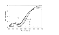
- FIG. 9 is a spectral reflection spectrum (direct incidence reflection spectral characteristic) in the wavelength region of 380 to 780 nm of the spectacle lens manufactured in Example 1.
- FIG. 9 is a spectral reflection spectrum (direct incidence reflection spectral characteristic) in the wavelength region of 380 to 780 nm of the spectacle lens manufactured in Example 1.
- FIG. 10 is a spectral transmission spectrum (direct incidence transmission spectral characteristic) in the wavelength region of 380 to 780 nm of the spectacle lens manufactured in Example 1.
- FIG. 11 is a reflection spectrum of reflected light (including return light from the eyeball side) with respect to incident light from obliquely above the spectacle lens manufactured in Example 1.
- 12 shows the film thickness (physical film thickness (unit: nm)) of each layer at five points on a straight line passing through the fitting point of each layer included in the multilayer film formed on the eyeball side surface in Example 2, and 380 to 780 nm. The normal-incidence average reflectance in the wavelength region is shown.
- FIG. 11 is a reflection spectrum of reflected light (including return light from the eyeball side) with respect to incident light from obliquely above the spectacle lens manufactured in Example 1.
- 12 shows the film thickness (physical film thickness (unit: nm)) of each layer at five points on a straight line passing through the fitting point of each layer included in the multilayer film formed on the
- FIG. 13 shows a spectral reflection spectrum (direct incidence reflection spectral characteristic) in the wavelength region of 380 to 780 nm of the spectacle lens manufactured in Example 2.
- FIG. 14 is a spectral transmission spectrum (normal incidence transmission spectral characteristic) in the wavelength region of 380 to 780 nm of the spectacle lens manufactured in Example 2.
- FIG. 15 is a reflection spectrum of reflected light (including return light from the eyeball side) with respect to incident light from obliquely above the spectacle lens produced in Example 2.
- the spectacle lens of the present invention Having a film showing the property of reflecting light in a specific wavelength range on both the object-side surface and the eyeball-side surface of the lens substrate; and The reflectance of the coating on one or both surfaces from the lower part to the upper part during wearing, or from the upper part to the lower part during wearing.
- a spectacle lens having a reflectance gradient that decreases continuously or stepwise, It is.
- at least one of the reflective films provided on both surfaces of the spectacle lens has a reflectance gradient as described above, so that light incident on the spectacle lens from the rear of the wearer can be reflected or It is possible to reduce a decrease in wearing feeling of the spectacle lens by being returned light and entering the eyes of the wearer.
- the spectacle lens of the present invention will be described in more detail.
- the spectacle lens of the present invention has a film (reflective film) showing the property of reflecting light of a specific wavelength on both the object side surface and the eyeball side surface of the lens substrate.
- the reflective film may be formed directly on the surface of the lens substrate, or may be indirectly formed on the lens substrate via one or more functional films.
- the lens substrate is not particularly limited, but styrene resin including (meth) acrylic resin, polycarbonate resin, allyl resin, allyl carbonate resin such as diethylene glycol bisallyl carbonate resin (CR-39), vinyl resin, polyester resin, Polyether resins, urethane resins obtained by reacting isocyanate compounds with hydroxy compounds such as diethylene glycol, thiourethane resins obtained by reacting isocyanate compounds with polythiol compounds, and having one or more disulfide bonds in the molecule (thio) Examples thereof include a transparent resin obtained by curing a polymerizable composition containing an epoxy compound. Inorganic glass can also be used.
- the refractive index of the lens substrate is, for example, about 1.60 to 1.75. However, the refractive index of the lens substrate is not limited to this, and may be within the above range or vertically away from the above range.
- the spectacle lens of the present invention can be various lenses such as a single focus lens, a multifocal lens, and a progressive power lens.
- a progressive-power lens normally, a near portion region (near portion) and a progressive portion region (intermediate region) are included in the lower region, and a far portion region (distance portion). Is included in the upper region.
- the type of lens is determined by the surface shape of both surfaces of the lens substrate.
- the lens substrate surface may be a convex surface, a concave surface, or a flat surface. In a normal lens substrate, the object side surface is convex and the eyeball side surface is concave.
- the lens substrate used in the present invention is not limited to this.
- a hard coat layer can be exemplified.
- the spectacle lens can be provided with scratch resistance (abrasion resistance), and the durability (strength) of the spectacle lens can be increased.
- scratch resistance abrasion resistance
- durability strength
- the functional film a primer layer for improving adhesion may be formed.
- the primer layer reference can be made to, for example, paragraphs 0029 to 0030 of JP2012-128135A.
- the reflection film is a film having a property of reflecting light in a specific wavelength region as described above.
- the “reflecting property” means, for example, that the direct incidence reflectance with respect to light in the wavelength region is 1% or more.
- the light in the specific wavelength range include light in the wavelength range of 380 nm to 780 nm (visible light), and light in the wavelength range of 280 nm to 400 nm (ultraviolet light).
- examples of the light in the specific wavelength region include short wavelength light (blue light) having a wavelength of about 400 to 500 nm described above.
- the reflective film is usually formed as a multilayer film in which a high refractive index layer and a low refractive index layer are laminated in any combination. More specifically, based on the refractive index of the film material for forming the high refractive index layer and the low refractive index layer and the wavelength of light to be reflected, the film thickness of each layer is determined by optical simulation using a known method, The multilayer film can be formed by sequentially laminating the high refractive index layer and the low refractive index layer under the film forming conditions determined to have the determined film thickness. Coatings having the property of reflecting visible light and ultraviolet rays are known, and for details, for example, known techniques such as JP-A-2000-66149 and JP-A-4524877 can be referred to.
- the film having the property of reflecting blue light reference can be made to, for example, paragraphs 0023 to 0030 of JP-A-2012-93689.
- a high refractive material for forming a high refractive index layer in a film having the property of reflecting blue light Ta 2 O 5 , ZrO 2 , TiO 2 , Al 2 O 3 , Y 2 O 3 , HfO 2 are used. And an oxide selected from the group consisting of Nb 2 O 5 .
- examples of the low refractive index material for forming the low refractive index layer include SiO 2 and MgF 2 .
- oxides and fluorides are shown in a stoichiometric composition, but oxygen or fluorine deficient or excessive from the stoichiometric composition is also used as a high refractive index material or a low refractive index material. It can be used.
- the film thickness of each layer included in the multilayer film can be determined by optical simulation.
- each of the above layers is formed by vapor deposition using a vapor deposition source containing the above-described high refractive index material or low refractive index material as a main component.
- the main component is a component that occupies the most in the vapor deposition source, and is usually a component that occupies about 50% by mass to 100% by mass, further about 90% by mass to 100% by mass.
- the vapor deposition source may contain a small amount of impurities inevitably mixed in, and plays a role of assisting other components such as other inorganic substances and vapor deposition within a range that does not impair the function of the main component.
- a known additive component may be contained.
- the vapor deposition in the present invention includes a dry method such as a vacuum vapor deposition method, an ion plating method, a sputtering method and the like.
- a dry method such as a vacuum vapor deposition method, an ion plating method, a sputtering method and the like.
- an ion beam assist method in which an ion beam is simultaneously irradiated during deposition may be used.
- the multilayer film includes one or more conductive oxide layers formed by vapor deposition using a vapor deposition source containing a conductive oxide as a main component. It can also be included in any position of the multilayer film.
- the conductive oxide it is preferable to use indium oxide, tin oxide, zinc oxide, titania and complex oxides thereof known as transparent conductive oxides so as not to lower the transparency of the spectacle lens.
- a particularly preferable conductive oxide from the viewpoint of transparency and conductivity is indium-tin oxide (ITO).
- the reflective film on one surface has a reflectance with respect to light in the specific wavelength range from a portion located below when worn to a portion located above or vice versa,
- the reflectance gradient decreases continuously or stepwise from the portion located at the bottom to the portion located below.
- the portion of the vapor deposition surface of the spectacle lens that is located above or below during wearing is used. It is preferable to arrange a shielding member above.
- the deposition amount of the vapor deposition material on the portion where the shielding member is disposed on the upper side is smaller than that on the other portions, so the film thickness of the vapor deposition film formed in this process is the portion located above during wearing Can be changed continuously or stepwise toward the lower part.
- FIG. 1 is a schematic process diagram showing an example of a method for producing a reflective film in which the reflectance with respect to light in a specific wavelength region changes continuously or stepwise from an upper region to a lower region during wearing.
- the spectacle lens substrate is illustrated as a flat lens, but the spectacle lens substrate in the present invention is not limited to a double-sided plane. This point is as described above.
- the vapor deposition source is disposed below the spectacle lens substrate and the vapor deposition material is evaporated toward the upper spectacle lens substrate surface, but the arrangement of the spectacle lens substrate and the vapor deposition material is as follows. The reverse is also possible.
- the lens substrate is placed in a vapor deposition apparatus with the deposition surface of the lens substrate facing the vapor deposition source.
- a known vapor deposition apparatus can be used as the vapor deposition apparatus.
- An example of the vapor deposition apparatus that can be used in the present invention will be described in the following examples.
- the portion located above or below the portion between the vapor deposition surface of the lens substrate and the vapor deposition source during wearing A shielding member is disposed above (FIG. 1A).
- the shielding member is disposed in a space without being brought into close contact with the deposition surface of the lens substrate.
- the vapor deposition material evaporates from below, a large amount of the vapor deposition material is deposited on the surface of the lens substrate on which the shielding member is not present.
- a slight amount of vapor deposition material is deposited near the boundary with the non-existing portion, and the deposition amount decreases as the distance from the boundary increases (FIG.
- vapor deposition films having different thicknesses in the plane can be provided in at least one layer in the multilayer film, and two or more layers can be provided.
- the reflectance with respect to light in a specific wavelength region decreases as the thickness of the low refractive index layer is reduced, and the reflectance increases as the thickness of the high refractive index layer is increased.
- the film thickness of the low refractive index layer thicker than the upper part in the portion located below during wearing, or from the upper part in the portion located below the high refractive index layer during wearing.
- the reflectance of the portion located below can be increased more than the upper portion.
- the aspect in which the reflectance with respect to light in a specific wavelength region increases as the film thickness of the low refractive index layer is reduced, and the reflectance decreases as the film thickness of the high refractive index layer is increased.
- the reflectance of the part located below can be raised rather than upper direction.
- positioning and removal of a shielding member will complicate a manufacturing process. Therefore, from the viewpoint of simplification of the process, the vapor deposition process performed by arranging the shielding member should be the first process or the last process of the multiple vapor deposition processes, that is, the first layer or the uppermost layer of the multilayer film. It is preferable to form the step.
- the reflective film provided on at least one of the object-side surface and the eyeball-side surface of the lens substrate has the above-described reflection gradient.
- a reflective film provided with a reflectance gradient a low reflectance region and a high reflectance region exist. For example, one of a region located below the fitting point (lower region) and a region located above this region (upper region) when the spectacle lens is worn is a low reflectance region, and the other is a high reflectance.
- the difference in reflectance with respect to light in the specific wavelength region in both regions is the difference in normal incidence average reflectance [(direct incidence average reflectance in high reflectance region) ⁇ (direct incidence average in low reflectance region) The reflectance)] is preferably 2% or more. From the viewpoint of preventing the difference in the reflection characteristics between the two regions from greatly affecting the appearance and wearing feeling of the spectacle lens, the difference is preferably 14% or less.
- the normal incidence average reflectance with respect to light in the specific wavelength region in the high reflectance region and the low reflectance region means a value of the normal incidence average reflectance measured at one or more points in the region. The average value, the maximum value, or the minimum value of the values measured as described above may be used.
- the measurement points can be about 2 to 10 points, for example.
- the difference may be a difference between an average value of normal incidence average reflectance measured in a high refractive index region and an average value of normal incidence average reflectance measured in a low refractive index region. Alternatively, it may be a difference between the maximum value of the normal incidence average reflectance measured in the high refractive index region and the minimum value of the normal incidence average reflectance measured in the low refractive index region.
- a reflective film having a reflectance gradient in the plane can be formed by providing a film thickness distribution.
- a reflective film having no reflectance gradient can be formed by setting the film thickness to a uniform film thickness without having a film thickness distribution.
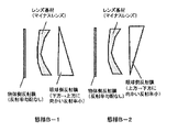
- the shape of the spectacle lens (lens base material) is roughly classified into a minus lens whose central part thickness is thinner than the peripheral part thickness and a positive part whose central part thickness is thicker than the peripheral part thickness.
- examples of the arrangement of the coating film having a reflectance gradient when the lens substrate is a minus lens can include the above-described aspects A and B.
- the aspect C , D can be mentioned.
- these aspects will be described in more detail.
- Aspect A (the lens base material is a minus lens) is an aspect having a film having a reflectance gradient on at least the object-side surface of the lens base material, and includes the following aspects A-1 to A-3.
- FIG. 2 is a schematic diagram showing the arrangement of the reflective films in the embodiments A-1 to A-3.
- Aspect A-1> An eyeball having a coating on the object side surface having a reflectance gradient in which the reflectance with respect to light in a specific wavelength region continuously or stepwise decreases from a portion located below to a portion located above when worn.
- the spectacle lens which has a film which has a reflectance gradient which the reflectance with respect to the said light reduces continuously or in steps from the part located in the downward direction to the part located in the upper part on the side surface.
- ⁇ Aspect A-2> An eyeball having a coating on the object side surface having a reflectance gradient in which the reflectance with respect to light in a specific wavelength region continuously or stepwise decreases from a portion located below to a portion located above when worn.
- the spectacle lens which has a film which has a reflectance gradient which the reflectance with respect to the said light reduces continuously or in steps from the part located in the upper part to the part located in the downward direction on the side surface.
- ⁇ Aspect A-3> An eyeball having a coating on the object side surface having a reflectance gradient in which the reflectance with respect to light in a specific wavelength region continuously or stepwise decreases from a portion located below to a portion located above when worn.
- a spectacle lens having a coating with no reflectance gradient on the side surface.
- any of the spectacle lenses according to embodiments A-1 to A-3 is a spectacle lens having a reflection film having a reflectance gradient in which the upper region is a low reflectance region on the object side surface.
- the amount of light incident on the spectacle lens eyeball side surface from above the rear of the wearer is transmitted through the eyeball side surface, reflected on the object side surface, and incident on the wearer's eye as return light. Can be reduced.
- the light incident from the rear of the wearer has a large amount of light incident from the rear upper side because many light sources such as illumination light and sunlight are above.
- the light reflected from the spectacle lens eyeball side among the light incident from the rear upper side of the wearer is difficult to enter the eye of the wearer, while the spectacle lens eyeball side
- the light that passes through and reaches the object-side surface tends to be reflected on the object-side surface and easily enter the wearer's eyes as return light. Therefore, according to the aspects A-1 to A-3 in which the reflectance of the portion on the object side surface that reflects the light incident from above and behind the wearer and brings back the light is lowered, the return light is transmitted to the eye of the wearer. The amount of incident light can be reduced.
- the upper region is also a low reflectance region in the reflective film on the eyeball side surface.
- the amount of light incident from the upper rear side of the wearer is reflected by the eyeball side surface and incident on the wearer's eye is not large, but some incidence may occur.
- Aspect A-1 is advantageous in that the amount of light that is reflected by the eyeball side surface and incident on the wearer's eye can be reduced.
- the reflection film on the eyeball side surface has a reflectance gradient opposite to that of the reflection film on the object side surface. Therefore, in the reflection film on the eyeball side surface, the lower region is a low reflectance region. is there.
- the reflection film on the eyeball side surface is a film without a reflectance gradient. Since a film having no reflectance gradient is easy to form, the embodiment A-3 is advantageous from the viewpoint of production suitability.
- the reflective film on the eyeball side surface of aspect A-3 is preferably low from the viewpoint of reducing the amount of return light that is reflected by the eyeball side surface and enters the eye of the wearer.
- the reflectance of the coating on the eyeball side surface with respect to light in the specific wavelength region is the same as or lower than the reflectance of the low reflectance region of the object side surface.
- the normal incidence average reflectance of the coating on the eyeball side surface in the specific wavelength region is preferably equal to or less than the normal incidence average reflectance of the upper region (low reflectance region) of the coating on the object side surface.
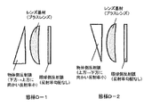
- Aspect B (the lens base material is a minus lens) is an aspect having a film having a reflectance gradient only on the eyeball side surface of the lens base material, and includes Aspects B-1 and B-2 below.
- FIG. 3 is a schematic diagram showing the arrangement of the reflective films in the embodiments B-1 and B-2.
- Aspect B-1> The eyeball side surface has a coating having a reflectance gradient in which the reflectance with respect to light in a specific wavelength region decreases continuously or stepwise from a portion located below to a portion located above when worn.
- a spectacle lens having a film having a reflectance gradient without reflecting on the object side surface.
- the eyeball side surface has a coating having a reflectance gradient in which the reflectance with respect to light in a specific wavelength region continuously or stepwise decreases from a portion located above to a portion located below when worn.
- a spectacle lens having a film having a reflectance gradient without reflecting on the object side surface.
- any of the spectacle lenses according to aspects B-1 and B-2 is an eyeglass lens having a film having no reflectance gradient on the object side surface, and in aspect B-1, the upper region of the film on the eyeball side surface, the aspect In B-2, the lower region of the coating on the eyeball side surface is the low reflectance region.
- the minus lens it is preferable to prevent the light incident from the upper rear side of the wearer from entering the eye of the wearer as the return light above the object side surface. From this point, it is preferable that the reflectance of the object side coating of the spectacle lens according to Embodiments B-1 and B-2 with respect to light in the specific wavelength range is low.
- the reflectance of the coating on the object side surface with respect to the light in the specific wavelength range is the same as that of the low reflectance region of the eyeball side surface, or Lower is preferred. More specifically, whether the coating on the eyeball side surface has a normal incidence average reflectance in the specific wavelength region in the lower region higher than a normal incidence average reflectance in the specific wavelength region in the upper region located above the region. Or the small normal incidence average reflectance in the specific wavelength range of the coating on the object side surface in the upper region or the lower region of the coating on the eyeball side surface is a region where the normal incidence average reflectance is low (low reflectance region). It is preferable that it is below the normal incidence average reflectance.
- the upper region of the eyeball-side surface is a low-reflectance region
- the amount of light that is incident on the eye of the wearer after the light incident from the upper rear side of the wearer is reflected by the eyeball-side surface This is advantageous in that it can be reduced.
- the lower region of the eyeball side surface is the low reflectance region
- the light incident from the lower rear side of the wearer is reflected by the eyeball side surface and is incident on the wearer's eye. This is advantageous in that the amount can be reduced.
- the lens substrate is a minus lens.
- the lens substrate is a plus lens.
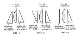
- Aspect C (the lens base material is a plus lens) is an aspect having a film having a reflectance gradient at least on the eyeball side surface of the lens base material, and includes the following aspects C-1 to C-3.
- FIG. 4 is a schematic diagram showing the arrangement of the reflective film in Embodiments C-1 and C-2.
- ⁇ Aspect C-1> An object having a reflectance gradient on the eyeball-side surface, the reflectance of which decreases continuously or stepwise from the portion positioned below to the portion positioned above from the portion positioned below when worn.
- the spectacle lens which has a film which has a reflectance gradient which the reflectance with respect to the said light reduces continuously or in steps from the part located in the downward direction to the part located in the upper part on the side surface.
- ⁇ Aspect C-2> An object having a reflectance gradient on the eyeball-side surface, the reflectance of which decreases continuously or stepwise from the portion positioned below to the portion positioned above from the portion positioned below when worn.
- the spectacle lens which has a film which has a reflectance gradient which the reflectance with respect to the said light reduces continuously or in steps from the part located in the upper part to the part located in the downward direction on the side surface.
- ⁇ Aspect C-3> An object having a reflectance gradient on the eyeball-side surface, the reflectance of which decreases continuously or stepwise from the portion positioned below to the portion positioned above from the portion positioned below when worn.
- any of the spectacle lenses according to embodiments C-1 to C-3 is a spectacle lens having a reflection film having a reflectance gradient in which the upper region is a low reflectance region on the eyeball side surface. According to this aspect, it is possible to reduce the amount of light that is incident on the eyeglass-side surface from the upper rear side of the wearer and reflected on the eyeball-side surface and is incident on the wearer's eye. In the plus lens, the light reflected from the eyeball side surface of the spectacle lens easily enters the eye of the wearer among the light incident from the upper rear side of the wearer due to the shape of the lens. The return light on the side surface tends to be difficult to enter the wearer's eyes.
- aspects C-1 to C-3 in which the reflectance of the portion of the eyeball side surface that reflects the light incident from behind the wearer is lowered, the amount of reflected light incident on the eye of the wearer Can be reduced.
- the upper region is also a low reflectance region in the reflection film on the object side surface. For the above reasons, the amount of light incident from the rear upper side of the wearer is reflected on the object-side surface and is incident on the wearer's eyes as return light, but some incidence may occur.
- Aspect C-1 is advantageous in that the amount of light that is reflected by the object-side surface and incident on the wearer's eye can be reduced.
- the reflection film on the object side surface has a reflectance gradient opposite to that of the reflection film on the eyeball side surface. Therefore, in the reflection film on the object side surface, the lower region is a low reflectance region. is there. In this way, by giving different reflectance gradients to the reflective films on both sides of the lens, the appearance and wearing feeling of the spectacle lens changes due to the presence of the reflectance gradient.
- Aspect C-2 is advantageous in that it can be counteracted by.
- the reflection film on the object side surface is a film without a reflectance gradient. Since a film having no reflectance gradient is easy to form, the embodiment C-3 is advantageous from the viewpoint of production suitability.
- the reflection film on the object-side surface of the aspect C-3 is preferably low from the viewpoint of reducing the amount of return light that is incident on the eye of the wearer after the light incident from the eyeball side is reflected on the object-side surface.
- the reflectance of the coating on the eyeball side surface with respect to light in the specific wavelength region is the same as or lower than the reflectance of the low reflectance region of the eyeball side surface.
- the normal incidence average reflectance in the specific wavelength region of the coating on the object side surface is preferably equal to or lower than the normal incidence average reflectance in the upper region (low reflectance region) of the coating on the eyeball side surface.
- Aspect D (the lens base is a plus lens) is an aspect having a film having a reflectance gradient only on the object side surface of the lens base, and includes Aspects D-1 and D-2 below.
- FIG. 4 is a schematic diagram showing the arrangement of the reflective film in Embodiments D-1 and D-2.
- the object-side surface has a coating having a reflectance gradient in which the reflectance with respect to light in a specific wavelength region decreases continuously or stepwise from a portion located below to a portion located above when worn.
- a spectacle lens having a coating film having a reflectance gradient and having a property of reflecting the light on the eyeball side surface.
- the object-side surface has a coating having a reflectance gradient in which the reflectance with respect to light in a specific wavelength region decreases continuously or stepwise from a portion located above to a portion located below when worn.
- a spectacle lens having a coating film having a reflectance gradient and having a property of reflecting the light on the eyeball side surface.
- any of the spectacle lenses according to aspects D-1 and D-2 is an eyeglass lens having a film without a reflectance gradient on the eyeball side surface, and in aspect D-1, the upper region of the film on the object side surface, the aspect In D-2, the lower region of the coating on the object side surface is the low reflectance region.
- the reflectance of the eyeball side coating of the spectacle lens according to Embodiments D-1 and D-2 with respect to light in the specific wavelength range is low.
- the reflectance of the coating on the eyeball side surface with respect to light in the specific wavelength range is the same as or lower than the reflectance of the low reflectance region of the object side surface. Lower is preferred. More specifically, whether the coating on the object side surface has a normal incidence average reflectance in the specific wavelength region in the lower region larger than a normal incidence average reflectance in the specific wavelength region in the upper region located above the region. Or the small normal incidence average reflectance in the specific wavelength region of the coating on the eyeball side surface in the region above or below the coating on the object side surface is a region where the normal incidence average reflectance is low (low reflectance region) It is preferable that it is below the normal incidence average reflectance.
- the upper region of the object-side surface is a low-reflectance region
- the light incident from the upper rear side of the wearer is reflected by the object-side surface and enters the wearer's eyes as return light. This is advantageous in that the amount of light can be reduced.
- the lower area of the object-side surface is a low reflectance area
- the light incident from the lower rear side of the wearer is reflected by the object-side surface and is incident on the wearer's eyes as return light. This is advantageous in that the amount of light to be reduced can be reduced.
- the spectacle lens of the present invention has the above-described reflective film on both lens surfaces. It is also possible to form a further functional film on the reflective film on one or both sides. Examples of such a functional film include a water-repellent or hydrophilic antifouling layer. For details, refer to paragraphs 0040 to 0042 of JP2012-128135A.
- the spectacle lens of the present invention described above has a good wearing feeling because the amount of light (return light or reflected light) caused by light incident from behind the wearer can be reduced in the wearer's eyes. It is.
- lens base material a plastic lens base material for eyeglasses with a refractive index of 1.67 (trade name: Seiko Super Sovereign (SSV)) which is a minus lens (progressive power lens). ) (Manufactured by HOYA).
- SSV Seiko Super Sovereign
- a coating solution (coating solution) for forming the hard coat layer was prepared as follows. Epoxy resin-silica hybrid (trade name: Composeran E102 (manufactured by Arakawa Chemical Co., Ltd.)) and 20 parts by weight of acid anhydride curing agent (trade name: curing agent liquid (C2) (manufactured by Arakawa Chemical Industry Co., Ltd.) )) 4.46 parts by mass were mixed and stirred to obtain a coating solution.
- This coating solution was applied to each surface of the lens substrate on the object side surface and the eyeball side surface using a spin coater so as to have a predetermined thickness.
- the coated lens substrate was baked at 125 ° C.
- the lens base material on which the hard coat layers are formed on both sides in the above is also referred to as a lens sample.
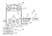
- Multilayer Film on Eyeball Side Surface and Object Side Surface Using the vapor deposition apparatus shown in FIG. 6, multilayer films were formed on the eyeball side surface and the object side surface, respectively.
- a multilayer film having no reflectance gradient is formed on the object side surface (convex surface), and a multilayer film is formed on the eyeball side surface (concave surface) so that the upper region is a low reflectance region.
- a spectacle lens according to Embodiment B-1 was obtained.
- the vapor deposition apparatus 100 illustrated in FIG. 6 can continuously form (manufacture) a plurality of vapor deposition films.
- the vapor deposition apparatus 100 is an electron beam vapor deposition apparatus, and includes a vacuum vessel 110, an exhaust device 120, and a gas supply device 130.
- the vacuum vessel 110 includes a sample support table 115 on which the lens sample 10 having a hard coat layer formed thereon is placed, a substrate heating heater 116 for heating the lens sample 10 set on the sample support table 115, and And a filament 117 for generating thermoelectrons.
- the substrate heating heater 116 is, for example, an infrared lamp, and heats the lens sample 10 to perform gas out or moisture removal to ensure adhesion of a layer formed on the surface of the lens sample 10.
- the vapor deposition apparatus 100 includes a storage unit 112 that stores a vapor deposition source 112a for forming a low refractive index layer, and a storage unit 113 that stores a vapor deposition source 113a for forming a high refractive index layer.
- the container 112 is provided with a crucible (not shown) for receiving the vapor deposition source 112a
- the container 113 is provided with a crucible (not shown) for receiving the vapor deposition source 113a.
- An electron gun (not shown) irradiates one of the vapor deposition sources (metal oxides) set in these crucibles with thermionic electrons 114 to evaporate them, and each layer is continuously formed on the lens sample 10.
- SiO 2 grains were used as the evaporation source 112a
- ZrO 2 sintered bodies were used as the evaporation source 113a.
- the vapor deposition apparatus 100 includes an ion gun 118 for accelerating and irradiating the lens sample 10 with a gas introduced into the vacuum vessel 110 in order to enable ion-assisted vapor deposition.
- the vacuum vessel 110 can be further provided with a cold trap for removing residual moisture, a device for managing the layer thickness, and the like.
- a device for managing the layer thickness for example, there is a reflective optical film thickness meter, a crystal oscillator thickness meter, or the like.
- the inside of the vacuum vessel 110 can be maintained at a high vacuum, for example, 1 ⁇ 10 ⁇ 4 Pa by a turbo molecular pump or cryopump 121 and a pressure control valve 122 included in the exhaust device 120.
- the inside of the vacuum vessel 110 can be set to a predetermined gas atmosphere by the gas supply device 130.
- argon (Ar) nitrogen (N 2 ), oxygen (O 2 ), and the like are prepared in the gas container 131 included in the gas supply device 130.
- the gas flow rate can be controlled by the flow rate control device 132, and the internal pressure of the vacuum vessel 110 can be controlled by the pressure gauge 135.
- the main vapor deposition conditions in the vapor deposition apparatus 100 are the vapor deposition material, the acceleration voltage and current value of the electron gun, and the presence or absence of ion assist.
- the conditions for using ion assist are given by the type of ions (atmosphere of the vacuum vessel 110), the acceleration voltage value of the ion gun 118, and the ion current value.
- the acceleration voltage of the electron gun is selected within the range of 5 to 10 kV and the current value within the range of 50 to 500 mA based on the film formation rate and the like.
- the ion gun 118 is selected in a voltage value range of 200 V to 1 kV and a current value in a range of 100 to 500 mA based on the film forming rate.
- the lens sample 10 on which the hard coat layer was formed was washed with acetone. Thereafter, a heat treatment at about 70 ° C. was performed inside the vacuum vessel 110 to evaporate water adhering to the lens sample 10. Next, ion cleaning was performed on the surface of the lens sample 10. Specifically, the ion gun 118 was used to irradiate the surface of the lens sample 10 with an energy of several hundred eV with an energy of several hundred eV to remove organic substances attached to the surface of the lens sample 10. By this treatment (method), the adhesion force of the layer (film) formed on the surface of the lens sample 10 can be strengthened.
- the same treatment may be performed using an inert gas such as argon (Ar) gas, xenon (Xe) gas, or nitrogen (N 2 ) instead of oxygen ions. Further, oxygen radicals or oxygen plasma may be irradiated.
- an inert gas such as argon (Ar) gas, xenon (Xe) gas, or nitrogen (N 2 ) instead of oxygen ions.
- oxygen radicals or oxygen plasma may be irradiated.
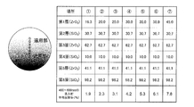
- the configuration (design value) of the multilayer film formed here is shown in FIG.
- the object side surface (convex surface) has a structure of round 1 to 7 and the eyeball side surface (concave face) has a structure of round 1.
- Mulls 1 to 3 are upper regions when worn, Mull 4 is a position that becomes a fitting point when worn, and Mulls 5 to 7 are locations that are located in the lower region when worn.
- the film thickness of the high refractive index layer of the first layer is gradually increased from the portion positioned above during wearing to the portion positioned below.
- a deposition process of alternately laminating a high refractive index layer and a low refractive index layer on the object side surface of the lens sample 10 by an electron beam vacuum deposition method is repeated, for a total of 6 layers.
- a multilayer film made of The SiO 2 layer, which is a low refractive index layer, was formed without performing ion assist.
- the heating conditions with an electron beam were a voltage of 6 kV and a current of 100 mA.
- argon gas was introduced into the vacuum vessel (chamber) 110 at 5 sccm.
- the ZrO 2 layer which is a high refractive index layer, was formed by performing ion assist (ion assist vapor deposition). Specifically, the heating conditions with an electron beam were a voltage of 6 kV and a current of 280 mA. At this time, as ion assist, a mixed gas of argon gas and oxygen gas was used, an ion acceleration voltage was set to 600 V, an ion beam current was set to 150 mA, and a mixed beam of argon and oxygen was irradiated. No gas was introduced into the vacuum container (chamber) 110. Further, the vapor deposition process of the first high refractive index layer (ZrO 2 layer) is illustrated in FIG.
- a mechanical mask shielding member
- the shielding member was disposed with a space on the lens using a holder (not shown).
- a space on the lens by providing a space on the lens and arranging the shielding member, the boundary between the upper region and the lower region becomes inconspicuous, and it is also possible to form a vapor deposition film whose film thickness continuously changes.
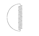
- a schematic plan view of the mechanical mask used here is shown in FIG.
- the boundary between the upper region and the lower region of the deposition surface is unclear in the deposited film as compared to the case of a straight line. This point is preferable in obtaining a spectacle lens having a good appearance.
- a similar effect can also be obtained by a shielding member in which the shape of the portion facing the boundary between the upper region and the lower region of the deposition surface is a shape including a curve such as a waveform.
- the vapor deposition apparatus was once opened and the mechanical mask was removed.
- the vacuuming is again performed and the vapor deposition is resumed.
- the remaining 16.3 nm thickness of the first layer was deposited, and the second and subsequent layers were deposited thereon.
- the film thicknesses at the seven points on the straight line passing through the fitting points of the respective layers of the multilayer film thus formed are the values indicated by circles 1 to 7 in FIG.
- the lens sample having the multilayer film formed on the eyeball side surface was turned over and placed in a vapor deposition apparatus, and the multilayer film was formed on the object side surface (concave surface) in the same manner as described above.
- a mechanical mask was not used, and vapor deposition with a uniform film thickness was performed on the entire surface. Specifically, vapor deposition was continuously performed from the first layer to the sixth layer with the structure of circle 1 in FIG.
- the multilayer film on the object side surface has a film thickness distribution in the first layer as shown in FIG.
- FIG. 8 shows the normal incidence average reflectance in the wavelength range of 400 to 500 nm at the above-mentioned seven points
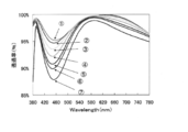
- FIG. 9 shows the obtained spectral reflection spectrum.
- the normal incidence average reflectance at 400 to 500 nm at the fitting point on the object side surface was 1.9% as in the position of the circle 1 in FIG.
- the measurement wavelength interval can be arbitrarily set, and can be set to 1 nm, for example. As shown in FIG. 9, it can be confirmed that the direct incidence reflectance in the wavelength region of 400 to 500 nm gradually increases from the region located above during wearing to the region located below.
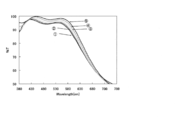
- the spectrophotometer U-4100 manufactured by Hitachi, Ltd. is used to transmit the direct-incidence transmission spectral characteristics in the wavelength range of 380 to 780 nm (the eyeball side surface is transmitted with respect to the amount of light incident on the object side surface).
- the ratio of the amount of light was measured (wavelength pitch: 10 nm).
- the obtained spectral transmission spectrum is shown in FIG. From the results shown in FIG. 10, it can be confirmed that the blue light amount that enters from the object side surface, passes through the eyeball side, and enters the wearer's eye in the lower region of the spectacle lens is lower than that in the upper region.
- the lower area is an area that is mainly used when the wearer looks at a blue light source (such as a monitor screen of a digital device such as a personal computer, a smartphone, or a tablet terminal). In this area, the blue color to the eye of the wearer If the amount of incident light can be reduced, the burden on the eye caused by blue light can be effectively reduced.
- a blue light source such as a monitor screen of a digital device such as a personal computer, a smartphone, or a tablet terminal.
- FIG. 11 shows a fluorescent eyeglass lens that was erected so that the upper region was on the upper side and the lower region was on the lower side.
- This is a spectrum of reflected light that is reflected by each part in the surface of the eyeball side surface, including the return light reflected by the object side surface.
- the spectrum was created by calculating the average value of the reflected light with respect to P-polarized light and the reflected light with respect to S-polarized light in the wavelength range of 380 to 780 nm by converting the normal incident spectral reflection characteristic into an incident angle of 45 degrees.
- the spectacle lens of the present example is a film having a property of reflecting light having a wavelength of 400 to 500 nm on both surfaces of the lens, but as shown in FIG. The rate is low.
- Example 2 2-1. Formation of multilayer film on object side surface and eyeball side surface A multilayer film is formed on the object side surface and eyeball side surface in the same manner as in Example 1 except that the film forming material and film thickness are changed as shown in FIG.
- the spectacle lens according to Embodiment B-1 was obtained. Note that the multilayer film on the object side surface has the structure of circle 5 in FIG.
- FIG. 12 shows the normal incidence average reflectance in the wavelength range of 380 to 780 nm at the above five points
- FIG. 13 shows the obtained spectral reflection spectrum.
- the normal incidence average reflectance at 380 to 780 nm at the fitting point on the object side surface was 10.8% as in the position of circle 5 in FIG. Note that the spectral reflection spectrum shown in FIG.
- the measurement wavelength interval can be arbitrarily set, and can be set to 1 nm, for example.
- the spectrophotometer U-4100 manufactured by Hitachi, Ltd. is used to transmit the direct incident transmission spectral characteristics in the wavelength region of 380 to 780 nm (transmits the eyeball side surface with respect to the amount of light incident on the object side surface). The ratio of the amount of light was measured (wavelength pitch: 10 nm). The obtained spectral transmission spectrum is shown in FIG.
- FIG. 15 shows a spectacle lens produced by placing a spectacle lens upright with the upper region on the upper side and the lower region on the lower side.
- This is a spectrum of reflected light that is reflected by each part in the surface of the eyeball side surface, including the return light reflected by the object side surface.
- the spectrum was created by calculating the average value of the reflected light with respect to P-polarized light and the reflected light with respect to S-polarized light in the wavelength range of 380 to 780 nm by converting the normal incident spectral reflection characteristic into an incident angle of 45 degrees.
- the reflectance is lower in the upper part.
- the present invention is useful in the field of manufacturing eyeglass lenses.
Landscapes
- Physics & Mathematics (AREA)
- Health & Medical Sciences (AREA)
- Ophthalmology & Optometry (AREA)
- General Physics & Mathematics (AREA)
- Optics & Photonics (AREA)
- Chemical & Material Sciences (AREA)
- General Health & Medical Sciences (AREA)
- Spectroscopy & Molecular Physics (AREA)
- Engineering & Computer Science (AREA)
- Materials Engineering (AREA)
- Mechanical Engineering (AREA)
- Metallurgy (AREA)
- Organic Chemistry (AREA)
- Chemical Kinetics & Catalysis (AREA)
- Inorganic Chemistry (AREA)
- Eyeglasses (AREA)
- Optical Filters (AREA)
- Surface Treatment Of Optical Elements (AREA)
Priority Applications (6)
| Application Number | Priority Date | Filing Date | Title |
|---|---|---|---|
| CA2922722A CA2922722A1 (en) | 2013-08-30 | 2014-09-01 | Spectacle lens |
| EP14840144.1A EP3040763A4 (en) | 2013-08-30 | 2014-09-01 | Spectacle lens |
| US14/914,727 US20160209679A1 (en) | 2013-08-30 | 2014-09-01 | Spectacle lens |
| AU2014312744A AU2014312744B2 (en) | 2013-08-30 | 2014-09-01 | Spectacle lens |
| KR1020167005633A KR20160034419A (ko) | 2013-08-30 | 2014-09-01 | 안경 렌즈 |
| CN201480047606.9A CN105683819A (zh) | 2013-08-30 | 2014-09-01 | 眼镜镜片 |
Applications Claiming Priority (2)
| Application Number | Priority Date | Filing Date | Title |
|---|---|---|---|
| JP2013-180229 | 2013-08-30 | ||
| JP2013180229A JP6313941B2 (ja) | 2013-08-30 | 2013-08-30 | 眼鏡レンズ |
Publications (1)
| Publication Number | Publication Date |
|---|---|
| WO2015030246A1 true WO2015030246A1 (ja) | 2015-03-05 |
Family
ID=52586790
Family Applications (1)
| Application Number | Title | Priority Date | Filing Date |
|---|---|---|---|
| PCT/JP2014/072964 Ceased WO2015030246A1 (ja) | 2013-08-30 | 2014-09-01 | 眼鏡レンズ |
Country Status (8)
| Country | Link |
|---|---|
| US (1) | US20160209679A1 (https=) |
| EP (1) | EP3040763A4 (https=) |
| JP (1) | JP6313941B2 (https=) |
| KR (1) | KR20160034419A (https=) |
| CN (1) | CN105683819A (https=) |
| AU (1) | AU2014312744B2 (https=) |
| CA (1) | CA2922722A1 (https=) |
| WO (1) | WO2015030246A1 (https=) |
Cited By (1)
| Publication number | Priority date | Publication date | Assignee | Title |
|---|---|---|---|---|
| CN108139613A (zh) * | 2015-10-02 | 2018-06-08 | 3M创新有限公司 | 滤光片 |
Families Citing this family (8)
| Publication number | Priority date | Publication date | Assignee | Title |
|---|---|---|---|---|
| JP3166809B2 (ja) | 1994-06-09 | 2001-05-14 | 戸田工業株式会社 | 針状磁性酸化鉄粒子粉末の製造法 |
| TWI542919B (zh) * | 2014-08-15 | 2016-07-21 | 萬能光學科技有限公司 | 一種可有效阻隔藍光和紅外光之光學鏡片真空蒸鍍方法 |
| MY192280A (en) | 2015-11-25 | 2022-08-17 | Tsubota Lab Inc | Optical element |
| JP7117081B2 (ja) * | 2017-05-12 | 2022-08-12 | Hoya株式会社 | 防塵レンズ及びその製造方法 |
| CN110174717A (zh) * | 2019-05-06 | 2019-08-27 | 厦门大学 | 一种蓝光防护光学薄膜及其制造方法 |
| WO2021220513A1 (ja) * | 2020-05-01 | 2021-11-04 | 株式会社ニコン・エシロール | 光学部材 |
| IT202000030104A1 (it) * | 2020-12-07 | 2022-06-07 | Out Of S R L | Maschera di protezione per gli occhi per la pratica di sport invernali |
| JP2023169755A (ja) * | 2022-05-17 | 2023-11-30 | 東海光学株式会社 | 眼鏡レンズ |
Citations (7)
| Publication number | Priority date | Publication date | Assignee | Title |
|---|---|---|---|---|
| JP2000066149A (ja) | 1998-08-21 | 2000-03-03 | Seiko Epson Corp | ミラーコート付きサングラス |
| JP4524877B2 (ja) | 2000-07-17 | 2010-08-18 | コニカミノルタホールディングス株式会社 | 眼鏡用レンズ |
| JP2011511330A (ja) * | 2008-02-07 | 2011-04-07 | ジェイク グルーバー | フィルター層を備えた網膜メラトニン抑制装置 |
| JP2011081232A (ja) * | 2009-10-08 | 2011-04-21 | Seiko Epson Corp | 眼鏡レンズ |
| JP2012093689A (ja) | 2010-09-29 | 2012-05-17 | Nikon-Essilor Co Ltd | 光学部品およびその製造方法 |
| JP2012128135A (ja) | 2010-12-15 | 2012-07-05 | Seiko Epson Corp | 光学物品およびその製造方法 |
| JP2012198330A (ja) * | 2011-03-18 | 2012-10-18 | Fujifilm Corp | 光学部材及びその製造方法 |
Family Cites Families (7)
| Publication number | Priority date | Publication date | Assignee | Title |
|---|---|---|---|---|
| US4160584A (en) * | 1976-05-17 | 1979-07-10 | Polaroid Corporation | Transparent metallic coating and a glass overcoating on a plastic substrate produce a chromatic effect |
| US5182588A (en) * | 1991-07-01 | 1993-01-26 | Maurer Robert D | Lens for filtering visible and ultraviolet electromagnetic waves during dental procedures |
| US6805903B2 (en) * | 2000-08-29 | 2004-10-19 | Japan Science And Technology Corporation | Method of forming optical thin film |
| US6814440B2 (en) * | 2002-01-10 | 2004-11-09 | Intercast Europe S.P.A. | Lenses having chromatic effect |
| KR101681657B1 (ko) * | 2008-06-13 | 2016-12-12 | 군나르 옵틱스, 엘엘씨 | 컴퓨터 시각 증후군의 증상들을 감소시키기 위한 저배율 아이웨어 |
| US20130053187A1 (en) * | 2011-08-25 | 2013-02-28 | Patrick Slater | Eyewear For Sports |
| JP5969194B2 (ja) * | 2011-10-31 | 2016-08-17 | Hoya株式会社 | 眼鏡レンズの製造方法 |
-
2013
- 2013-08-30 JP JP2013180229A patent/JP6313941B2/ja active Active
-
2014
- 2014-09-01 US US14/914,727 patent/US20160209679A1/en not_active Abandoned
- 2014-09-01 CA CA2922722A patent/CA2922722A1/en not_active Abandoned
- 2014-09-01 CN CN201480047606.9A patent/CN105683819A/zh active Pending
- 2014-09-01 EP EP14840144.1A patent/EP3040763A4/en not_active Withdrawn
- 2014-09-01 KR KR1020167005633A patent/KR20160034419A/ko not_active Ceased
- 2014-09-01 AU AU2014312744A patent/AU2014312744B2/en not_active Ceased
- 2014-09-01 WO PCT/JP2014/072964 patent/WO2015030246A1/ja not_active Ceased
Patent Citations (7)
| Publication number | Priority date | Publication date | Assignee | Title |
|---|---|---|---|---|
| JP2000066149A (ja) | 1998-08-21 | 2000-03-03 | Seiko Epson Corp | ミラーコート付きサングラス |
| JP4524877B2 (ja) | 2000-07-17 | 2010-08-18 | コニカミノルタホールディングス株式会社 | 眼鏡用レンズ |
| JP2011511330A (ja) * | 2008-02-07 | 2011-04-07 | ジェイク グルーバー | フィルター層を備えた網膜メラトニン抑制装置 |
| JP2011081232A (ja) * | 2009-10-08 | 2011-04-21 | Seiko Epson Corp | 眼鏡レンズ |
| JP2012093689A (ja) | 2010-09-29 | 2012-05-17 | Nikon-Essilor Co Ltd | 光学部品およびその製造方法 |
| JP2012128135A (ja) | 2010-12-15 | 2012-07-05 | Seiko Epson Corp | 光学物品およびその製造方法 |
| JP2012198330A (ja) * | 2011-03-18 | 2012-10-18 | Fujifilm Corp | 光学部材及びその製造方法 |
Non-Patent Citations (1)
| Title |
|---|
| See also references of EP3040763A4 |
Cited By (1)
| Publication number | Priority date | Publication date | Assignee | Title |
|---|---|---|---|---|
| CN108139613A (zh) * | 2015-10-02 | 2018-06-08 | 3M创新有限公司 | 滤光片 |
Also Published As
| Publication number | Publication date |
|---|---|
| EP3040763A4 (en) | 2017-04-26 |
| EP3040763A1 (en) | 2016-07-06 |
| AU2014312744B2 (en) | 2017-06-22 |
| JP2015049339A (ja) | 2015-03-16 |
| KR20160034419A (ko) | 2016-03-29 |
| CA2922722A1 (en) | 2015-03-05 |
| US20160209679A1 (en) | 2016-07-21 |
| CN105683819A (zh) | 2016-06-15 |
| AU2014312744A1 (en) | 2016-04-21 |
| JP6313941B2 (ja) | 2018-04-18 |
Similar Documents
| Publication | Publication Date | Title |
|---|---|---|
| JP6313941B2 (ja) | 眼鏡レンズ | |
| WO2015030245A1 (ja) | 眼鏡レンズおよびその製造方法 | |
| JP5622468B2 (ja) | レンズの製造方法及びレンズ | |
| US20110033635A1 (en) | Method for Producing Optical Article | |
| CN104838305A (zh) | 光学元件、光学元件的制造方法、及重影光的定量方法 | |
| US20140347625A1 (en) | Optical Component, Spectacle Lens, and Method of Manufacturing the Same | |
| KR102770674B1 (ko) | 내마모성을 개선하기 위한 간섭 코팅 및 다층 시스템을 갖는 광학 렌즈 | |
| KR20210092739A (ko) | 내마모성을 개선하기 위한 필터링 간섭 코팅 및 다층 시스템을 갖는 광학 렌즈 | |
| WO2016146153A1 (en) | Optical article comprising an antireflective coating in the visible region for low luminance conditions | |
| KR20210092737A (ko) | 내마모성을 개선하기 위한 향상된 간섭 코팅 및 다층 시스템을 갖는 광학 렌즈 | |
| JP5698902B2 (ja) | 光学物品およびその製造方法 | |
| KR20210092740A (ko) | 내마모성을 개선하기 위한 거울 코팅 및 다층 시스템을 갖는 광학 렌즈 | |
| JP2015049339A5 (https=) | ||
| CN105980916A (zh) | 眼镜镜片 | |
| JP5867794B2 (ja) | 眼鏡レンズの製造方法および光学物品の製造方法 | |
| KR102775471B1 (ko) | 내마모성이 높은 간섭 코팅을 갖는 광학 물품 | |
| JP2010072635A (ja) | 光学物品およびその製造方法 | |
| JP2010072636A (ja) | 光学物品およびその製造方法 | |
| JP5922324B2 (ja) | 光学物品およびその製造方法 | |
| JP2011017949A (ja) | 光学物品の製造方法およびその方法により製造された光学物品 | |
| JP2009210677A (ja) | 眼鏡レンズ及びその製造方法 | |
| WO2025206325A1 (ja) | 眼鏡レンズの製造方法 | |
| BR112021006664B1 (pt) | Artigo óptico tendo um revestimento interferencial com uma elevada resistência à abrasão e método de fabricação de um artigo óptico | |
| JP2016075964A (ja) | 光学物品およびその製造方法 |
Legal Events
| Date | Code | Title | Description |
|---|---|---|---|
| 121 | Ep: the epo has been informed by wipo that ep was designated in this application |
Ref document number: 14840144 Country of ref document: EP Kind code of ref document: A1 |
|
| ENP | Entry into the national phase |
Ref document number: 2922722 Country of ref document: CA |
|
| WWE | Wipo information: entry into national phase |
Ref document number: 14914727 Country of ref document: US |
|
| NENP | Non-entry into the national phase |
Ref country code: DE |
|
| ENP | Entry into the national phase |
Ref document number: 20167005633 Country of ref document: KR Kind code of ref document: A |
|
| REEP | Request for entry into the european phase |
Ref document number: 2014840144 Country of ref document: EP |
|
| WWE | Wipo information: entry into national phase |
Ref document number: 2014840144 Country of ref document: EP |
|
| ENP | Entry into the national phase |
Ref document number: 2014312744 Country of ref document: AU Date of ref document: 20140901 Kind code of ref document: A |