WO2015029988A1 - ダイシング装置及びダイシング方法 - Google Patents
ダイシング装置及びダイシング方法 Download PDFInfo
- Publication number
- WO2015029988A1 WO2015029988A1 PCT/JP2014/072268 JP2014072268W WO2015029988A1 WO 2015029988 A1 WO2015029988 A1 WO 2015029988A1 JP 2014072268 W JP2014072268 W JP 2014072268W WO 2015029988 A1 WO2015029988 A1 WO 2015029988A1
- Authority
- WO
- WIPO (PCT)
- Prior art keywords
- blade
- dicing
- workpiece
- diamond
- cutting
- Prior art date
- Legal status (The legal status is an assumption and is not a legal conclusion. Google has not performed a legal analysis and makes no representation as to the accuracy of the status listed.)
- Ceased
Links
Images
























Classifications
-
- B—PERFORMING OPERATIONS; TRANSPORTING
- B24—GRINDING; POLISHING
- B24B—MACHINES, DEVICES, OR PROCESSES FOR GRINDING OR POLISHING; DRESSING OR CONDITIONING OF ABRADING SURFACES; FEEDING OF GRINDING, POLISHING, OR LAPPING AGENTS
- B24B27/00—Other grinding machines or devices
- B24B27/06—Grinders for cutting-off
-
- B—PERFORMING OPERATIONS; TRANSPORTING
- B24—GRINDING; POLISHING
- B24B—MACHINES, DEVICES, OR PROCESSES FOR GRINDING OR POLISHING; DRESSING OR CONDITIONING OF ABRADING SURFACES; FEEDING OF GRINDING, POLISHING, OR LAPPING AGENTS
- B24B19/00—Single-purpose machines or devices for particular grinding operations not covered by any other main group
- B24B19/02—Single-purpose machines or devices for particular grinding operations not covered by any other main group for grinding grooves, e.g. on shafts, in casings, in tubes, homokinetic joint elements
- B24B19/028—Single-purpose machines or devices for particular grinding operations not covered by any other main group for grinding grooves, e.g. on shafts, in casings, in tubes, homokinetic joint elements for microgrooves or oil spots
-
- B—PERFORMING OPERATIONS; TRANSPORTING
- B24—GRINDING; POLISHING
- B24B—MACHINES, DEVICES, OR PROCESSES FOR GRINDING OR POLISHING; DRESSING OR CONDITIONING OF ABRADING SURFACES; FEEDING OF GRINDING, POLISHING, OR LAPPING AGENTS
- B24B27/00—Other grinding machines or devices
- B24B27/0076—Other grinding machines or devices grinding machines comprising two or more grinding tools
-
- B—PERFORMING OPERATIONS; TRANSPORTING
- B24—GRINDING; POLISHING
- B24D—TOOLS FOR GRINDING, BUFFING OR SHARPENING
- B24D5/00—Bonded abrasive wheels, or wheels with inserted abrasive blocks, designed for acting only by their periphery; Bushings or mountings therefor
- B24D5/12—Cut-off wheels
Definitions
- the present invention relates to a dicing apparatus and a dicing method for performing a cutting process such as cutting or grooving on a workpiece such as a wafer on which a semiconductor device or an electronic component is formed.
- a dicing apparatus that divides a workpiece such as a wafer on which a semiconductor device or an electronic component is formed into individual chips includes at least a dicing blade that is rotated at high speed by a spindle, a work table on which the work is placed, a work table and a blade X, Y, Z, and ⁇ moving axes that change the relative position of the workpiece are provided, and the workpieces are subjected to cutting processing such as cutting and grooving by the operations of these moving axes.
- Patent Document 1 diamond abrasive grains are bonded to an end surface of a metal base material (aluminum flange) by an electroforming method using an electroplating technique using an alloy with a soft metal such as nickel or copper as a binder. A casting blade is described.
- Patent Document 2 describes a diamond blade composed of a base material composed of a plurality of diamond layers by sequentially laminating diamond layers having different hardnesses by chemical vapor deposition (CVD).
- CVD chemical vapor deposition
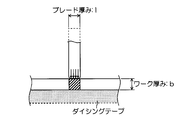
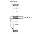
- the cutting process is performed with a dicing blade having a blade thickness larger than the thickness of the workpiece, the workpiece may be broken before being cut. For this reason, for example, when performing grooving processing with a depth of about 30 ⁇ m on a workpiece with a thickness of about 50 ⁇ m, the width of the groove must naturally be 30 ⁇ m or less. It is necessary to suppress it to 30 ⁇ m or less.
- the conventional dicing blade has the following technical problems, and it is impossible to stably and accurately cut an extremely thin workpiece.
- a ductile material such as copper, aluminum, an organic film, or a resin is not cracked, but has a property of easily generating burrs, and it is difficult to avoid the generation of burrs.
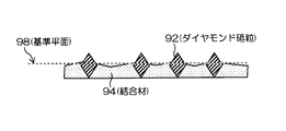
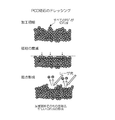
- the cause of this problem is the surface form of the electroformed blade. That is, as shown in FIG. 21, in the electroformed blade, diamond abrasive grains 92 are bonded by a binder 94, but the surface form is such that diamond abrasive grains 92 are scattered in the binder 94. Existing. Therefore, in the electroformed blade, the reference plane 98 that is the overall average height position exists near the surface of the binder 94, and the diamond abrasive grains 92 protrude from the reference plane 98.
- the diamond abrasive grains 92 worn during cutting are dropped off as they are, and then the new diamond abrasive grains 92 underneath act.
- the dropped diamond abrasive grains 92 enter between the blade and the workpiece, and consequently promote cracks.
- the electroformed blade has poor thermal conductivity, and heat is likely to be accumulated in the blade due to heat generated by frictional resistance with the groove side surface during cutting, which may cause warpage of the blade.
- the thermal conductivity of nickel is at most about 92 W / m ⁇ K. Even when copper is used as a binder, it has only a thermal conductivity of about 398 W / m ⁇ K. In this way, if the blade has poor thermal conductivity, heat is likely to accumulate, and the blade may warp or diamond may be graphitized due to heat generated during processing, so cooling and processing with pure water is performed. There are many cases.
- the thermal conductivity of diamond is 2100 W / m ⁇ K, which is orders of magnitude higher than that of nickel and copper.
- the diamond blade is formed by a CVD method, the blade is formed by a very dense film. As a result, the surface of the diamond blade is almost flat and arbitrarily cut. Therefore, it is impossible to form a recess shape or a pocket for removing chips. Even if fine irregularities are formed as a result, the grain boundary size cannot be arbitrarily set before film formation. Therefore, it is not possible to arbitrarily design the uneven pitch.
- the outer peripheral portion (tip portion) of the blade is as thin as possible.
- the portion that contacts the flange is warped to maintain a highly accurate reference plane. A thickness that does not occur is required.
- the blade is manufactured as a single piece, if the blade has such portions having different thicknesses, it cannot be manufactured as a single piece by the film forming method, which is substantially impossible. For this reason, joining different types of materials deforms due to thermal stress and disturbs the roundness and flatness, so that it is possible to realize ductile mode processing as in the present invention described later. It can be difficult.
- grinding or cutting when a workpiece is machined in a state where spiral or streamlined chips are produced, it is called ductile mode machining.
- the configuration in which a diamond chip with a high hardness is embedded in the outer periphery of the blade has different thermal expansion and thermal conductivity between the diamond part and the base part.
- the temperature distribution does not become a clean temperature distribution that is axisymmetric, and the flatness is also deteriorated by thermal stress.
- the base material portion may absorb the impact received by the diamond tip due to the elastic effect of the metal portion of the base material.
- the base material portion may absorb the impact received by the diamond tip due to the elastic effect of the metal portion of the base material.
- the relative speed is set to 0 so that the workpiece and blade do not slip.
- the blade configuration in the case of scribing, the blade needs to rotate freely in order to apply a vertical stress to the material, and the bearing or shaft portion in the blade is pressed vertically downward.
- the present invention is not a scribing, the motor and the blade are directly connected, and there is no relationship between the shaft and the bearing, and the fitting is incorporated in a coaxial configuration with high precision.
- the dicing blade requires a reference plane for matching with the flange end face.
- the workpiece is not a flat sample, it may not be possible to fix the workpiece successfully. For example, when a cylindrical workpiece is cut as it is, the workpiece moves and the cut is not constant, and the workpiece may vibrate due to cutting.
- a material in which a ductile material and a brittle material are mixed such as a Cu / Low-k material (a material in which a copper material and a low dielectric constant material are mixed).
- a ductile material such as low-k materials
- the workpiece must be machined within the deformation zone of the material so as not to cause brittle fracture.
- Cu is a ductile material
- these materials tend to be very elongated while not cracking.
- Such a highly ductile material clings to the blade and generates a large burr at the part where the blade comes off. In many cases, circular blades form a burr like a beard on the top.
- a highly ductile material has a problem of clinging to the blade if the material is dragged by the blade even after cutting.
- clinging to the blade clogging of the blade is accelerated, and the cutting edge portion of the blade is covered with the work material, resulting in a problem that the grinding ability is remarkably lowered.
- the present invention has been made in view of such circumstances, and it is possible to stably and accurately perform a cutting process in a ductile mode without generating a crack or a crack even on a workpiece made of a brittle material.
- An object of the present invention is to provide a dicing apparatus and a dicing method capable of performing the above.
- a dicing apparatus for cutting a workpiece, and is configured in a disk shape by a diamond sintered body formed by sintering diamond abrasive grains, A dicing blade having a minute cutting edge continuous in the circumferential direction of the outer peripheral portion, a rotating mechanism for rotating the dicing blade, and giving the workpiece a cutting depth by the dicing blade, the workpiece to the dicing blade A moving mechanism for relatively moving.
- the diamond sintered body preferably has a content of the diamond abrasive grains of 80 vol% (hereinafter also simply referred to as “%”) or more.
- the dicing apparatus is a dicing apparatus for cutting a workpiece, wherein the diamond sintered body is configured by a diamond sintered body formed by sintering diamond abrasive grains, and the diamond sintered body Is a dicing blade in which the content of the diamond abrasive grains is 80 vol% or more, a rotating mechanism for rotating the dicing blade, and a given cutting depth is given to the work by the dicing blade, whereby fine particles are introduced into the dicing blade. And a moving mechanism for moving the workpiece relative to the dicing blade.
- a dicing method is a dicing method for cutting a workpiece, in which a dicing blade configured in a disk shape is rotated by a diamond sintered body formed by sintering diamond abrasive grains.
- the diamond sintered body preferably has a content of the diamond abrasive grains of 80 vol% or more.
- the dicing blade cuts the workpiece while rotating in the down cut direction.
- the down cut direction refers to a rotation direction in which the cutting edge of the dicing blade cuts into the work surface when the work is moved relative to the dicing blade.
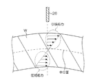
- the dicing apparatus has means for applying a tensile stress to the surface of the workpiece to be processed.
- the outer peripheral part of the said dicing blade is continuously provided with the cutting edge (micro cutting edge) which consists of a recessed part formed in the surface of the said diamond sintered compact along the circumferential direction. Is preferred.
- the diamond protrudes because the binding material recedes compared to the diamond, and as a result, the diamond abrasive grains protrude larger than the average level line. As a result, an excessive depth of cut occurs in the abrasive grain portion where the protrusion amount is large, and cracks are caused beyond the critical depth of cut inherent to the material.
- the dicing blade is almost composed of diamond, and the recessed portion surrounded by diamond is the cutting edge. For this reason, the protruding abrasive grains are not formed. As a result, the depth of cut does not become excessive, and the recess acts as a cutting edge. Since the flat reference surface is a diamond surface and there are concave portions in some places, basically, the concave portion is processed as a cutting edge.
- the diamond abrasive grains exist predominantly in the whole, and the cutting edge to be formed is formed in the diamond abrasive grains due to the presence of the sintering aid left diffused between them. It becomes the cutting edge of the dent that was made.
- the empty portion acts as a cutting edge.
- the concave portion is not formed in the outer edge formed by the diamond abrasive grains, but the concave and convex portions are almost the same, or the convex portions are dominant and relatively protruding portions This is a cutting edge that gives a stable depth of cut below a certain level that does not cause fatal cracks in the workpiece.
- the blade according to the present invention is characterized by being composed of sintered diamond.
- Sintered diamond is manufactured by increasing the temperature and pressure by spreading diamonds with a uniform particle size in advance and adding a small amount of sintering aid.
- the sintering aid diffuses into the diamond abrasive grains, and as a result, the diamonds are strongly bonded to each other.
- Electrodeposition blades and electroformed blades do not bond diamonds together. This is a method in which diamond abrasive grains are hardened by hardening diamonds with surrounding metal.
- the diamond particles are firmly connected to each other as the sintering aid diffuses into the diamond.
- the diamond characteristics can be utilized by bonding the diamond particles together. If the diamond content is large in the rigidity, hardness, heat conduction, etc. of diamond, it becomes possible to make use of physical properties almost similar to diamond. This is because diamonds are bonded together.
- diamonds are connected by being fired at high temperature and pressure.
- a sintered diamond corresponds to, for example, Compax Diamond (trademark) manufactured by GE.
- Compaq diamond combines fine particles composed of single crystals with a sintering aid.
- a member produced by vapor phase growth by CVD like DLC diamond-like carbon
- CVD diamond-like carbon
- the size of the crystal grain boundary cannot be controlled accurately. For this reason, it is impossible to set the degree of uniform wear even when worn from the grain boundary, and it is not possible to strictly control the crystal units and grain boundary units that are worn away by processing. Therefore, it may happen that a large defect is occasionally generated, or that some defects are excessively stressed and cracked greatly.
- PCD Polycrystalline Diamond
- the diamond fine particles themselves are single crystals, and are complete crystals with very high hardness.
- single crystals are combined by mixing a sintering aid. At that time, since the bonding portions are not completely aligned, the whole is bonded not as a single crystal but as a polycrystal. Therefore, there is no crystal orientation dependency even in the wear process, and it has a certain large strength in any direction.
- the initial state can be maintained with high accuracy in terms of the state of the outer peripheral cutting edge and the pitch unit of the outer peripheral cutting edge during the wear process in machining.
- the portion connecting the single crystal and the single crystal is relatively weak in terms of hardness and strength rather than cracking the single crystal itself, so the bond is broken from the grain boundary portion and falls off I will do it.
- the blade according to the present invention is particularly effective in combination with the PCD configuration and the disk shape.
- a cutting edge exists on the outer periphery of the disk shape, and reaches the machining point in such a manner that it sequentially acts on the machining point.
- the cutting edge does not always exist at the machining point during machining, and contributes to machining only by the pole arc while rotating. Therefore, since the machining and cooling are repeated, the tip portion is not excessively heated. As a result, diamond does not react thermochemically and contributes to processing stably.
- the formation of equally spaced cutting edges is an indispensable element for ductile mode dicing, which is the subject of the present invention described later. That is, in the ductile mode dicing, as will be described later, the cutting depth given to the material by one cutting edge is important, and the cutting depth given to the workpiece by one cutting edge is the "cutting edge interval on the outer periphery of the blade" However, it is concerned with the necessary elements.
- the relationship between the critical depth of cut and the cutting edge interval given to a workpiece by one blade at this point will be described later, but in order to define the critical cutting depth of one blade, it is essential to set a stable cutting edge interval. .
- PCD in which single crystal abrasive grains having a uniform particle diameter are sintered and bonded together is suitable.
- the diamond blade arrangement in the PCD material in the present invention and the conventional blade in which the diamond abrasive grains are arranged in other general cases Describe the differences.
- the content of abrasive grains is small. Also in Japanese Patent Application Laid-Open No. 2010-005778 and the like, the content of diamond abrasive grains in the abrasive layer is about 10%. Therefore, it is unlikely that the abrasive content will exceed 70%. Therefore, each abrasive grain exists sparsely. Although it arrange
- Japanese Patent No. 3308246 describes a dicing blade for cutting rare earth magnets, which is formed of a composite sintered body of diamond and / or CBN (Cubic Boron Nitride).
- the content of diamond or CBN is 1 to 70 vol%, more preferably 5 to 50%. When the diamond content exceeds 70%, there is no problem in terms of warping and bending, but it is weak against impact and easily broken.
- Japanese Patent No. 4714453 also discloses a tool for cutting and grooving composite materials such as ceramics, metal and glass.
- abrasive grains are contained in an amount of 3.5 to 60 vol% in the firing pair.
- the technical problem here is that the holding power of the abrasive grains is high even if the bond material has a high elastic modulus and high hardness, and it is said that sufficient protrusion of the abrasive grains can always be maintained with the described configuration. It is described that by sufficiently maintaining “abrasive grain protrusion”, the self-generated blade can be effectively maintained to enable high-speed machining.
- the electroformed blade nor the diamond sintered body blade is filled with a gap between the abrasive grains.
- the gap between the spread abrasive grains is a cutting edge.
- a critical cutting depth given by one cutting edge is important, and in order to keep the cutting depth below a certain level, the interval between cutting edges Becomes important.
- the cutting blades are not made of isolated and protruding abrasive grains, but diamonds are laid down to form equally spaced cutting edges using the laid recessed portions.
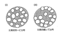
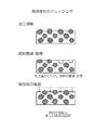
- FIG. 22A and 22B schematically show the state of the abrasive grain spacing according to the diamond abrasive grain content.
- a cutting edge that does not give excessive cutting at a constant abrasive grain interval
- at least 70% or more of the diamond abrasive grain content is required for spreading.
- some diamond must be removed.
- Sintering with a diamond abrasive content of 80% or more can form a state in which diamonds are spread at least spatially without gaps as shown in FIG. 22A.
- all the irregularities thus formed act as cutting edges.
- the content of diamond abrasive grains be 70% or less in order to solve the problem of performing high-speed machining under sufficient abrasive grain protrusion.
- the subject of the present invention is to perform crack-free dicing in the ductile mode. Therefore, in order to make the dent portion between the abrasive grains act as a cutting edge and keep the interval between the cutting edges constant, the diamond content should be at least 70%, ideally 80%. It is desirable that there be more.
- the blade is not simply cut with a sharp blade like a cutter.
- the tip is not manufactured with a sharp blade and cut on the principle of pinching. It is necessary to remove the workpiece while cutting and make a groove. It is necessary to continuously cut the next blade into the material while discharging chips continuously. Therefore, it is not necessary for the tip to be sharp, but a fine cutting edge is required.
- the cutting edge portion forms not only the grain boundary portion but also a constant cutting edge interval due to the natural roughness of the outer peripheral portion.
- a cutting edge interval will be shown later as a specific example, but the diamond particle size and the cutting edge interval may be quite different.
- the concept of cutting edge differs from that of a normal electroformed blade. That is, in the conventional blade, since diamond is embedded in the binder, each diamond exists independently, and therefore the size of the cutting edge is the same as the diamond particle size. That is, one diamond forms one cutting edge.
- the unit of the self-generated blade is each diamond, that is, corresponds to each cutting edge.
- the unit of cutting edge and the unit of self-generated blade do not change. For example, when it is necessary to catch on the workpiece to some extent, it is necessary to make the cutting edge larger because the cutting is necessary.
- the self-generated blade also increases the unit of self-generated blade because the abrasive grains fall off accordingly. As a result, the life is extremely shortened.
- the blade using the sintered diamond of the present invention small diamonds are bonded to each other.
- a cutting edge larger than the diamond particle is formed on the outer periphery of a sintered diamond blade formed by bonding diamonds together.
- the particle diameter of diamond, which is each abrasive grain constituting the sintered body is as small as about 1 ⁇ m.
- each diamond falls off during processing, but the entire cutting edge does not fall off. Also, when falling off, the abrasive grains constituting one cutting edge like an electroformed blade do not fall off, but in the part where diamonds are bonded, some diamonds are missing and fall off become.
- the diamond is peeled off by abrasion in a region smaller than the size of the cutting edge, and the size of the cutting edge itself does not change greatly.
- dicing progresses while peeling off very finely.
- the size of the cutting edge itself does not change, and on the other hand, the entire cutting edge is not worn out and the sharpness does not deteriorate.
- the maximum depth of cut per cutting edge is kept within a certain range while being small and partially self-generated. As a result, it is possible to maintain the ductility mode processing and achieve both stable sharpness.
- the part where the diamond is missing becomes a small dent
- the dent part also exists as a fine cutting edge existing in a large cutting edge as a region surrounded by another diamond abrasive grain, Constructs a micro roughness that triggers the work. That is, the idea of the self-generated blade is completely different from the conventional configuration in that the diamond missing portion becomes the next cutting edge as it is.
- the concept of the cutting edge, the interval, and the critical cutting depth at which one cutting edge cuts are set as dicing conditions by setting a constant blade cutting with a blade that requires a cutting edge on the outer periphery. It is necessary to feed at a feed rate suitable for the workpiece. Therefore, a premise is an apparatus that operates the blade at a constant feed with a constant cut along the surface shape. When the workpiece is a flat surface, it is necessary to set a constant cut parallel to the workpiece surface to be processed and relatively feed the blade.
- the cutting edge keeps in contact with the workpiece.
- the cutting edge has heat due to friction, and even diamond may be worn away thermochemically. By cutting the blade into a workpiece while standing up, the diamond wear due to thermal influence can be largely avoided.
- the diamond sintered body is obtained by sintering the diamond abrasive grains using a soft metal sintering aid.
- the blade becomes conductive by using a soft metal as a sintering aid.
- a soft metal as a sintering aid.
- the blade uses a conductive blade, and keeps conduction between the conductive blade and the chuck plate that chucks the reference planar substrate, and when the conductive blade comes into contact with the chuck plate, The relative height of the blade and chuck plate can be found.
- the recess is preferably constituted by a recess formed by wearing or dressing the diamond sintered body.
- the diamond abrasive grains preferably have an average particle size of 25 ⁇ m or less.
- the diamond blade for cutting rare earth magnets is described. It is desirable that the diamond content is 1 to 70 vol% and the average particle diameter of diamond is 1 to 100 ⁇ m. It is said. In Example 1, the average particle size of diamond is 150 ⁇ m. This is intended to improve the wear resistance of the cored bar with less warping.
- the average particle size of diamond is effective when the average particle size is 10 to 100 ⁇ m, but more preferably the average particle size is 40 to 100 ⁇ m.
- JP-A-2003-326466 describes a blade for dicing ceramics, glass, resin, or metal, but the average particle size is preferably 0.1 ⁇ m to 300 ⁇ m.
- the average grain size of the diamond abrasive grains needs to be 25 ⁇ m or less in combination with the diamond content.
- the thickness direction In the blade thickness direction, if there is at least a width in which two to three fine particles exist in the thickness direction, it is impossible to form a strong blade itself in which abrasive grains are connected to each other. If it is composed of fine particles of 25 ⁇ m or more, the thickness direction must be at least 50 ⁇ m. However, in the case of a blade thicker than 50 ⁇ m in the thickness direction, the maximum cutting depth that one blade cuts is larger than the Dc value of 0.1 ⁇ m in SiC or the like because of the linearity of the existing cutting blade. Therefore, there is a possibility that the ductile mode is not finely formed, it becomes difficult to process the ideal ductile mode, and the probability of causing brittle fracture in principle becomes very large. This point will be described in detail later.
- the diamond particle size be 25 ⁇ m or less.
- the outer peripheral portion of the dicing blade is preferably configured to be thinner than the inner portion of the outer peripheral portion, and the thickness of the outer peripheral portion of the dicing blade is more preferably 50 ⁇ m or less.
- the outer peripheral portion of the dicing blade refers to the width of the portion that enters the workpiece.
- the part entering the work may break the work if the blade width is larger than the work thickness. This will be described in detail later.
- the rotating mechanism is provided with a metal flange surface perpendicular to a rotating shaft for rotating the dicing blade, and the dicing blade includes a reference plane portion on one side surface, and the reference plane portion It is preferable that the shaft is fixed to the rotating shaft in a state of being in contact with the flange surface. In this aspect, it is more preferable that the reference plane portion of the dicing blade is formed in an annular shape centering on the rotation axis.
- the die shim grade is integrally formed in a disk shape by a diamond sintered body (preferably the content of diamond abrasive grains is 80% or more). Therefore, it becomes possible to control the cutting depth of the dicing blade with respect to the workpiece with higher accuracy than the conventional electroformed blade. As a result, the workpiece can be moved relative to the dicing blade while giving a constant cutting depth to the workpiece without giving excessive cutting. As a result, even workpieces made of brittle materials can be cut with the cutting depth of the dicing blade set below the critical cutting depth of the workpiece without causing cracks or cracks. In addition, the cutting process can be performed stably and accurately in the ductility mode.
- FIG. 2 is a side sectional view showing a section AA in FIG. Enlarged sectional view showing an example of the configuration of the cutting edge part Expanded sectional view showing another example of the configuration of the cutting edge portion Enlarged sectional view showing still another example of the configuration of the cutting edge portion
- FIG. 1 is a perspective view showing an appearance of a dicing apparatus.
- the dicing apparatus 10 includes a load port 12 that transfers a cassette containing a plurality of workpieces W to and from an external device, and a conveyance unit that has a suction unit 14 and conveys the workpieces W to each unit.
- Means 16 imaging means 18 for imaging the surface of the workpiece W, a processing unit 20, a spinner 22 for cleaning and drying the processed workpiece W, and a controller 24 for controlling the operation of each part of the apparatus. ing.
- the processing unit 20 is provided with an air bearing spindle 28 with a built-in high-frequency motor that is disposed so as to face each other and have a blade 26 attached to the tip, and rotates at a predetermined rotational speed and is independent of each other. As a result, index feed in the Y direction and cut feed in the Z direction are performed.
- the work table 30 on which the work W is sucked and mounted is configured to be rotatable around the axis in the Z direction, and is configured to be ground and fed in the X direction in the figure by the movement of the X table 32. Yes.
- the work table 30 includes a porous chuck (porous body) that vacuum-sucks the work W using negative pressure.
- the work W placed on the work table 30 is held and fixed in a state of being vacuum-sucked by a porous chuck (not shown).
- a porous chuck not shown.
- the workpiece W which is a flat sample, is uniformly adsorbed over the entire surface while being flattened by the porous chuck. For this reason, even if a shear stress acts on the workpiece W during dicing, the workpiece W will not be displaced.
- Such a work holding method that vacuum-sucks the whole work leads to the blade constantly giving a constant cutting depth to the work.
- the reference surface of the workpiece surface can be defined and the blade cutting depth from the reference surface can be set, so the critical cutting depth per cutting edge can be set and stable. Ductile mode dicing can be performed.
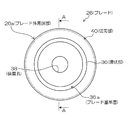
- FIG. 2 is a front view of the dicing blade.
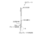
- FIG. 3 is a side sectional view showing the AA section of FIG.
- the dicing blade 26 of the present embodiment is a ring-type blade, and is attached to the spindle 28 of the dicing apparatus 10 at the center thereof.
- a mounting hole 38 is formed.
- the blade 26 is made of sintered diamond and has a disk shape or a ring shape. If the blade 26 has a concentric structure, the temperature distribution is axisymmetric. If the temperature distribution is axisymmetric with the same material, the shear stress accompanying the Poisson's ratio does not act in the radial direction. Therefore, the outer peripheral end portion maintains an ideal circular shape, and the outer peripheral end is maintained on the same plane, so that it acts on the workpiece in a straight line by rotation.
- the blade 26 is integrally formed in a disc shape by a diamond sintered body (PCD) formed by sintering diamond abrasive grains.
- This diamond sintered body has a diamond abrasive grain content (diamond content) of 80% or more, and each diamond abrasive grain is bonded to each other by a sintering aid (for example, cobalt or the like).
- the outer peripheral portion of the blade 26 is a portion cut into the work W, and a cutting blade portion 40 formed in a thin blade shape than the inner portion thereof is provided.
- a cutting edge (a minute cutting edge) made of a minute recess formed on the surface of the diamond sintered body has a minute pitch (along the circumferential direction of the blade outer peripheral end portion (outer peripheral edge portion) 26 a ( For example, 10 ⁇ m) is formed continuously.
- the thickness (blade thickness) of the cutting edge portion 40 is configured to be at least thinner than the thickness of the workpiece W.
- the thickness of the cutting edge portion 40 is preferably 50 ⁇ m or less, more preferably 30 ⁇ m or less, and further preferably 10 ⁇ m or less.
- the cross-sectional shape of the cutting edge portion 40 may be formed in a tapered shape in which the thickness gradually decreases toward the outer side (tip side), or may be formed in a straight shape having a uniform thickness.
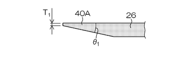
- FIG. 4A to 4C are enlarged cross-sectional views showing a configuration example of the cutting edge portion 40.
- FIG. 4A to 4C correspond to an enlarged portion of portion B in FIG.
- the cutting blade portion 40A shown in FIG. 4A is a one-side tapered type (one-piece V type) in which only one side surface portion is processed obliquely in a tapered shape.
- the thickness T 1 of the outermost end portion formed to be the thinnest is 10 ⁇ m
- the taper angle ⁇ 1 of the portion where the side surface portion on one side is processed into a tapered shape is 20 degrees.
- the inner portion of the blade 26 (excluding an annular portion 36 described later) has a thickness of 1 mm (the same applies to FIGS. 4B and 4C).
- the cutting edge portion 40B shown in FIG. 4B is of a double-sided taper type (both V-type) in which the side surfaces on both sides are processed obliquely in a tapered shape.
- the thickness T 2 of the outermost end portion formed to be the thinnest is 10 ⁇ m
- the taper angle ⁇ 2 of the portion where the side surface portions on both sides are processed into a tapered shape is 15 degrees. .
- the cutting blade portion 40C shown in FIG. 4C is of a straight type (parallel type) in which the side portions on both sides are processed in parallel in a straight shape.
- the thickness T 3 of the tip portion processed into the thinnest straight shape is 50 ⁇ m.
- the inner side portion (center side portion) of the straight tip portion has one side surface portion processed into a taper shape, and the taper angle ⁇ 3 is 20 degrees.
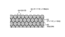
- FIG. 5 is a schematic view schematically showing a state near the surface of the diamond sintered body.
- the diamond sintered body 80 is in a state in which diamond abrasive grains (diamond particles) 82 are bonded to each other at a high density by the sintering aid 86.
- a cutting edge (microscopic cutting edge) 84 composed of a microscopic recess (concave) is formed.
- the recess 84 is formed by selectively wearing a sintering aid 86 such as cobalt by mechanically processing the diamond sintered body 80.
- the dent formed when the sintering aid 86 is worn becomes a minute pocket, and there is no protrusion of sharp diamond abrasive grains like an electroformed blade. (See FIG. 21).
- the dent formed on the surface of the diamond sintered body 80 functions as a pocket for conveying chips generated when the workpiece W is cut, and also functions as a cutting edge 84 that gives a cut to the workpiece W. To do.
- the chip discharge performance is improved, and the cutting depth of the blade 26 with respect to the workpiece W can be controlled with high accuracy.
- the blade 26 of the present embodiment is integrally constituted by a diamond sintered body 80 formed by sintering diamond abrasive grains 82 using a sintering aid 86.
- a sintering aid 86 there is very little sintering aid 86 in the gap between the diamond sintered bodies 80, but the sintering aid is also diffused in the diamond abrasive grains themselves, and in fact, the diamonds are firmly bonded together. It becomes a form to do. Cobalt, nickel, etc. are used for this sintering aid 86, and hardness is low compared with a diamond. Therefore, although the diamonds are bonded to each other, the portion rich in the sintering aid is slightly weaker than the single crystal diamond.
- Such a portion is worn and reduced when the workpiece W is processed, and becomes an appropriate recess with respect to the surface (reference plane) of the diamond sintered body 80. Further, by subjecting the diamond sintered body 80 to wear processing, a recess from which the sintering aid is removed is formed on the surface of the diamond sintered body 80. In addition, some diamonds are missing in addition to the sintering aid by sharpening with a grinding wheel of GC (Green Carborundum) or by cutting a cemented carbide which is a hard brittle material in some cases. Appropriate roughness is formed on the outer periphery of the diamond sintered body. By setting the roughness of the outer peripheral portion to be larger than the diamond particle size, a minute diamond abrasive grain is lost in one cutting edge, and the cutting edge is hardly worn.
- GC Green Carborundum
- the dent formed on the surface of the diamond sintered body 80 works advantageously for processing in the ductile mode.
- the dent functions as a pocket for discharging chips generated when the workpiece W is cut, and also functions as a cutting edge 84 that gives a cut to the workpiece W. For this reason, the amount of cut into the workpiece W is naturally limited to a predetermined range, and no fatal cut is given.
- the number, pitch, and width of the recesses formed on the surface of the diamond sintered body 80 are also arbitrarily determined. It becomes possible to adjust.
- the diamond sintered body 80 constituting the blade 26 of the present embodiment is obtained by bonding the diamond abrasive grains 82 to each other using the sintering aid 86.
- the sintering aid 86 there is a sintering aid 86 between the diamond abrasive grains 82 bonded to each other, and a grain boundary exists. Since this grain boundary portion corresponds to a dent, the pitch and number of the dents are naturally determined by setting the particle diameter (average particle diameter) of the diamond abrasive grains 82. Further, by using the sintering aid 86 using a soft metal, selective dent processing can be performed, and the sintering aid 86 can be selectively worn.
- the roughness can be adjusted by setting the wear process and the dressing process while rotating the blade 26. That is, the pitch, width, depth, and number of the cutting edges 84 formed of dents formed on the surface of the diamond sintered body 80 are determined depending on the pitch of the grain boundaries formed along with the selection of the grain size of the diamond abrasive grains 82. It becomes possible to adjust.
- the pitch, width, depth, and number of the cutting edges 84 play an important role in performing ductile mode processing.
- the desired grain size of the diamond abrasive grains 82 is adjusted along the crystal grain boundaries with high precision by appropriately adjusting parameters having good controllability such as wear processing and dressing processing.
- the spacing of the blades 84 can be achieved.
- the cutting edges 84 formed of dents formed on the surface of the diamond sintered body 80 in a straight line along the circumferential direction.
- a wheel used for scribing is disclosed in, for example, Japanese Patent Laid-Open No. 2012-030992.
- the above document discloses a wheel formed of sintered diamond and having an annular blade having a cutting edge on the outer peripheral portion.
- the scribing of the above document refers to a scribing line (longitudinal crack) on the surface of a substrate formed of a brittle material as described in the above paragraph [0020]. ), And vertical cracks extending in the vertical direction are generated by scribing (see paragraph [0022] above). Cleaving using this crack.
- the principle of the present invention is completely different as a processing method for removing material in a shearing manner without generating cracks or chipping. Specifically, since the blade itself rotates at high speed and acts almost horizontally with respect to the workpiece surface to remove the workpiece, no stress is applied in the vertical direction of the workpiece. In addition, since the depth of cut is limited within the deformation region of the material and processing is performed with a depth of cut that does not generate cracks, a crack-free surface is obtained as a result. From the above, the processing principle is completely different.
- ⁇ (Point of tip angle) Since scribing only generates cracks inside the material, it hardly enters the material. Since only the edge line of the cutting edge is applied, the cutting edge angle is usually an obtuse angle (see paragraph [0070] above). A sharp angle of 20 degrees or less cannot be considered at all in consideration of defects caused by twisting.
- dicing penetrates into the material and removes the part that entered, so the edge of the blade is straight or at most the apex angle of the blade is V-shaped to the extent that buckling due to dicing resistance in the blade traveling direction is considered. To some extent.
- the maximum apex angle is 20 degrees or less.
- the apex angle is 20 degrees or more
- the cross-section after cutting becomes oblique and the cross-sectional area increases, and in terms of machining mechanism, grinding is performed on the side of the blade rather than the element that the blade tip advances.
- the processing efficiency decreases, and sometimes the processing does not proceed.
- a cutting edge is formed on the outer periphery of the blade and the cutting edge at the tip is efficiently advanced, while the blade side surface is mirror-finished while improving the lubricity with the workpiece and reducing the amount of grinding. Is required.
- the amount of grinding on the side surface of the blade increases, the grinding amount on the side surface inevitably increases, and the cross section after cutting cannot be mirror-finished. Therefore, a straight shape is most desirable for dicing, but it is preferable that the shape is extremely small and V-shaped so that the blade does not buckle at least, and it is 20 degrees or less at most.
- dicing proceeds linearly while the blade rotates at a high speed to remove a certain amount of material. Therefore, no torsional stress is applied. Instead, if the diamond content is low, the apparent hardness will drop when cutting, so the reaction force from the workpiece and the workpiece will elastically recover within the time when the blade cutting edge is cut, The predetermined depth of cut may not be maintained. Therefore, in the case of dicing, the hardness of the blade is sufficiently high compared to the height of the workpiece so that the blade does not rebound and can be advanced with a predetermined cut.
- the surface hardness equivalent to that of single-crystal diamond (about 10000 Knoop hardness) is required to allow machining to proceed without allowing elastic recovery within the cutting edge working time during machining within the deformation range of the material.
- About 8000 in hardness is required.
- the diamond content needs to be 80% or more.
- the ratio of the sintering aid is extremely reduced, so that the bonding force between the diamonds is weakened, the toughness of the blade itself is lowered, and it becomes brittle and easily chipped. Therefore, the diamond content needs to be 80% or more, and considering the practical point, it is desirable to make it 98% or less.
- the scribing wheel has a holder, and the holder is an element that rotatably holds the scribing wheel. Since the holder mainly has a pin and a support frame, the pin portion (shaft portion) does not rotate. The inner diameter part of the wheel becomes a bearing and rotates by rubbing relatively with the pin part that is the shaft, thereby forming a vertical scribing line (longitudinal crack) on the material surface.
- the blade according to the present invention is mounted coaxially on the rotating spindle.
- the spindle and blade are integrally rotated at a high speed.
- the blade needs to be mounted perpendicular to the spindle axis, and it is necessary to eliminate runout due to rotation.
- the blade has a reference plane.
- the reference surface existing on the blade is fixed in contact with a reference end surface of a flange previously attached to the spindle in a vertical direction.
- the perpendicularity with respect to the spindle rotation axis of the blade is ensured. Only when this perpendicularity is secured, the cutting blade formed on the outer peripheral portion acts on the workpiece in a straight line when the blade rotates.
- the reference plane in the case of scribing is a cylindrical surface parallel to the axis of the disc blade, and is defined on the assumption that the blade is pressed vertically.
- the reference plane of the blade in the blade according to the present invention is the side end face (disk surface) of the blade facing the flange of the spindle as described above.
- ⁇ (Processing principle) The difference in principle between scribing and dicing according to the present invention is whether the processing is performed with cracks in the vertical direction or processing without generating any cracks.
- ⁇ (Role of groove of outer peripheral blade)
- the scribing is applied only to the surface by the vertical stress of the scriber to form a scribing line.
- the role of the groove of the outer peripheral blade in the case of scribing is to generate a crack perpendicular to the material while the protrusion at the blade edge of the wheel is in contact with the brittle material substrate (the above paragraph [0114] ]reference). That is, the groove other than the groove can be provided with a scribing line that can penetrate the material and cause vertical cracks. Therefore, it is more important how the crest portion between the grooves bites into the material rather than the groove.
- the recess provided at the outer peripheral end plays the role of a cutting edge.
- a portion between the recesses is set so as to form a contour of the outer periphery and to have a critical depth of cut so that a cutting edge provided therebetween does not crack the work surface. Therefore, in the case of dicing, it is necessary to form a cutting edge.
- the groove depth in the case of scribing is formed so as to give the amount of biting for attaching the scribing line, but in the case of dicing, the groove depth enters the work and the work piece is cut with each cutting edge. Must be removed by grinding. For this reason, the blade tip completely enters the workpiece, but the blade is not allowed to sway, and the cutting edge must act perpendicularly to the workpiece surface deeply into the material.
- the outer peripheral end portion has concave cutting edges with a constant interval. As will be described later, it is sufficient that the critical cutting depth given by one cutting edge does not cause cracks. For this purpose, it is necessary to keep the cutting edge distance appropriate.
- the direction of the cutting edge of the scribing wheel is changed by 90 degrees while the scribing hole is in contact with the brittle material, which is called a caster effect.
- the blade tip is embedded in the material, so the direction of the blade tip cannot be changed by 90 degrees. For example, if the cutting edge is changed while abutting with a dicing blade having a straight shape or an apex angle of 20 degrees or less, the blade breaks.
- wear treatment and dressing treatment are the most suitable methods for forming a dent on the surface. Not limited to.
- a sintering aid such as cobalt or nickel
- the diamond abrasive grains themselves act as cutting edges, but in order to adjust the pitch and width of the cutting edges, the degree of dispersion in which the diamond abrasive grains are initially dispersed It is technically difficult to rely on. That is, there is a lot of ambiguity of dispersion of diamond abrasive grains and it cannot be controlled substantially. Moreover, even if there are portions where the diamond abrasive grains are not sufficiently dispersed and agglomerated, or there are portions where the diamond abrasive grains are too dispersed and sparse, it is difficult to arbitrarily adjust this. As described above, it is impossible to control the arrangement of the cutting edges with the conventional electroformed blade.
- the average particle diameter of diamond abrasive grains contained in the diamond sintered body is preferably 25 ⁇ m or less (more preferably 10 ⁇ m or less, and even more preferably 5 ⁇ m or less).
- a cutting depth greater than or equal to a predetermined critical cutting depth is given as an isolated cutting edge, and as a result, the occurrence of chipping and cracking is extremely high.
- a diamond of about 50 ⁇ m falls off, not only the remaining cutting edge becomes large, but also the dropped diamond abrasive grains themselves are entangled between the workpiece and the blade and may cause further cracks. . If the particle size is 25 ⁇ m or less, such a crack has not been obtained.
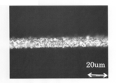
- FIG. 6 shows the surface of the workpiece when grooving is performed with a blade having an average particle diameter of diamond abrasive grains of 50 ⁇ m, and shows an example in which cracks are generated.
- Table 2 shows the results of evaluating the incidence of cracking or chipping when grooving with a blade with diamond abrasive grains having an average particle size of 50 ⁇ m, 25 ⁇ m, 10 ⁇ m, 5 ⁇ m, 1 ⁇ m, and 0.5 ⁇ m. Show.
- the evaluation results indicate that the occurrence rate of cracks or chipping increases in the order of A, B, C, and D. Other conditions are as follows.
- the average particle diameter of the diamond abrasive grains is 50 ⁇ m, it is difficult to reduce the blade thickness (the thickness of the outer peripheral edge of the blade) to 50 ⁇ m or less. There are many. Also, even if you try to manufacture a blade with a blade thickness of 100 ⁇ m (0.1mm), there is a part with a large gap, and it may be cracked by a slight impact, so it is realistic to manufacture the blade stably. Was difficult.
- each brittle material of SiC, sapphire, quartz, and silicon is cut in the same way as when the average particle diameter is 50 ⁇ m.
- no cracks occurred that is, in these brittle materials, when the average particle diameter of the diamond abrasive grains is 50 ⁇ m, cracks are generated by cutting in the order of submicron, and when diamond abrasive grains having an average particle diameter larger than that are used, the cutting is necessarily performed. Will increase and lead to fatal cracks.
- the cutting can be suppressed to be small and the cutting depth can be controlled with high accuracy. Is possible.
- the general processing conditions of this experiment are a blade outer diameter of 50.8 mm, a wafer size of 2 inches, a notch 10 ⁇ m grooving, a spindle rotation speed of 20,000 rpm, and a table feed speed of 5 mm / s.
- a diamond fine powder is placed on a base mainly composed of tungsten carbide and put in a mold.
- a solvent metal such as cobalt (sintering aid) is added to the mold as a sintering aid.
- it is fired and sintered in a high pressure of 5 GPa or higher and a high temperature atmosphere of 1300 ° C. or higher.
- a cylindrical ingot having a diameter of 60 mm, a sintered diamond layer (diamond sintered body) of 0.5 mm, and a tungsten carbide layer of 3 mm can be obtained.
- the diamond sintered body formed on tungsten carbide include DA200 manufactured by Sumitomo Electric Hardmetal Corporation.
- the blade 26 of this embodiment can be obtained by taking out only the diamond sintered body and subjecting the blade base material to a predetermined shape and subjecting it to peripheral wear or dressing.
- the diamond surface of the cylindrical ingot (excluding the cutting edge portion 40) is surface-roughened (arithmetic average) by performing skiff polishing (scaif, polishing disc) as a reference surface formation for eliminating vibration during rotation.
- Roughness Ra It is preferable to process a mirror surface of about 0.1 ⁇ m.
- the wear treatment and dressing treatment in the above production method can be performed under the following conditions.
- Wear processing includes the following conditions.
- the following conditions may be used for the dressing process (abrasion process).
- GC600 dressing wheel (70mm ⁇ ) (GC600 means that the particle size of the silicon carbide abrasive is 600 (# 600). The particle size is based on Japan Industrial Standards (JIS) R6001) -Processing time: 15 minutes-Even in this treatment, the cobalt sintering aid was slightly removed and dents were formed.
- JIS Japan Industrial Standards
- the outer periphery of the blade it is desirable to change the roughness of the outer periphery of the blade and the side surface of the blade.
- the outer peripheral edge of the blade corresponds to a cutting edge, and the cutting edge interval is adjusted along the crystal grain boundary by wear processing.
- the outer peripheral edge of the blade is slightly roughened since it is removed by machining to a certain extent while cutting the workpiece material.
- the blade side surface portion is not actively removed, but may be rough enough to cut out the groove side surface portion when contacting the groove side surface portion of the workpiece material.
- the blade side surface portion is finely roughened.
- the abrasive grains are solidified by plating, so that the entire surface has the same abrasive grain distribution, and as a result, the form of how the abrasive grains are attached to the blade outer peripheral edge and the blade side surface. I could not divide it. That is, the roughness condition could not be clearly changed between the outer peripheral edge of the blade for advancing the workpiece and the side portion that is finely scraped while rubbing against the workpiece.
- most of the blade is composed of diamond and can be molded from that state.
- diamond wrapping or the like may be performed in order to roughen the side surface portion.
- the blade outer periphery needs to be cut while machining the workpiece. Therefore, it is better to add roughness as a cutting edge unlike the side surface. Such roughness can form a cutting edge in an outer peripheral part with a pulse laser etc., for example.
- the following conditions are preferably used.
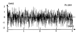
- Laser oscillator Fiber laser manufactured by IPG, USA: YLR-150-1500-QCW Feeding table: JK702 Wavelength: 1060nm Output: 250W Pulse width: 0.2msec Focal position 0.1mm Work speed 2.8rpm Gas: High purity nitrogen gas 0.1L / min Hole diameter 50 ⁇ m Work blade material: Sumitomo Electric DA150 (diamond particle size 5 ⁇ m) Outer diameter 50.8mm With such a pulsed fiber laser, as shown in FIG. 23, a semicircular sharp cutting edge continuous at a constant interval of 0.05 mm in diameter can be formed on the outer peripheral edge of the blade at a pitch of 0.1 mm.
- the diamond particle size is 5 ⁇ m, but one cutting edge itself can be a 50 ⁇ m cutting edge. If these are formed at equal intervals, the apparent interval is reduced by rotating the rotation speed at a high speed, and ductile mode dicing is enabled. (Example: When the spindle speed is 10,000 rpm or more).
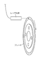
- FIG. 23 shows the result when a laser beam is incident from the normal direction of the blade surface (surface perpendicular to the rotation axis of the blade 26) to form a cutting edge.
- the size of a single cutting edge can be formed with various hole diameters, from a size of about 5 ⁇ m to 1 mm with a large one. It is possible to open up to about 200 ⁇ m.
- a notch Rather than forming a notch with a diamond-hardened material such as an electroforming method, it is made of sintered diamond material and a small notch is continuously formed at the outer periphery of the disk. Each notch acts as a cutting edge.
- Japanese Unexamined Patent Publication No. 2005-129741 describes a method of forming a notch in the outer peripheral portion of a blade manufactured by an electroforming method.
- the notch prevents a chip discharge function and clogging.
- Notches are provided as a function, not as cutting edges.
- diamond is not necessarily present at the edge of the notch, but is present together with the binding material, so that the binding material wears with processing, and thus acts as a cutting edge as a material. It is not a thing.
- the tip of the cutting edge vacated on the outer periphery acts as it is as a cutting edge.
- the diamond abrasive grain size is as small as 5 ⁇ m compared to the size of the cutting edge of 50 ⁇ m, one diamond abrasive grain is chipped off in one cutting edge, and it is possible to grow smaller in the cutting edge.
- the size of the cutting edge and the self-generated unit are the same size, but in the case of the present invention, an arbitrary cutting edge is formed.
- the size of the cutting edge and the unit in which the diamond grows can be changed, and as a result, the sharpness can be secured for a long time.
- the blade side surface can be mirror-finished while cutting the workpiece with a fine rough surface while cutting at the blade outer peripheral edge.
- Conventionally, with an electroforming blade it was difficult to change the roughness of the outer peripheral edge and the roughness of the side surface independently, and this could not be substantially achieved.
- a configuration for example, JP-A-7-276137, etc.
- the cutting edges may be formed at equal intervals. Since it is not formed by PCD, as described above, it gives local effective shearing force to the workpiece without absorbing the impact of heat conduction, shape flatness and plane continuity, and impact due to processing. It is obvious that the blade is completely different from the blade according to the present invention in that the processing is performed in the ductile mode.
- the distance between the cutting edges and the surface roughness of the side surface are appropriately adjusted according to the material to be processed.
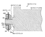
- FIG. 7 is a cross-sectional view showing a state where the blade 26 is attached to the spindle 28.
- the spindle 28 is supported by a spindle main body 44 incorporating a motor (high-frequency motor) (not shown), and is pivotally supported by the spindle main body 44, and its tip protrudes from the spindle main body 44.
- a spindle shaft 46 disposed on the main body.
- the hub flange 48 is a member interposed between the spindle shaft 46 and the blade 26, and is provided with a mounting hole 48a formed in a tapered shape and a cylindrical projection 48b.
- the hub flange 48 is provided with a flange surface 48c serving as a reference surface for determining the perpendicularity of the blade 26 to the spindle shaft 46 (rotation shaft).
- a blade reference surface 36a of the blade 26 is brought into contact with the flange surface 48c as will be described later.
- the blade 26 is provided with an annular portion (contact region) 36 formed thick on the inner side of the cutting edge portion 40 on one end face (see FIGS. 2 and 3).
- the annular portion 36 is formed with a blade reference surface 36a with which the flange surface 48c of the hub flange 48 abuts.
- the blade reference surface 36a is preferably provided at a higher position than the other positions on the end surface where the annular portion 36 is formed, thereby facilitating flatness. Further, the thickness of the annular portion 36 constituting the blade reference surface 36a needs to be sufficiently thicker than that of the cutting edge portion 40 provided on the outer peripheral portion of the blade.
- the blade outer periphery does not cause brittle fracture on the material surface at the time of cutting, so it is necessary to make the cutting width narrow, and the thickness must be 50 ⁇ m or less.
- the processing distortion at the time of processing in the process of taking out the flat surface of the blade becomes a big problem.
- the entire surface of the blade is manufactured with a thickness of about 50 ⁇ m, the blade warps to one side due to the balance of strains on both sides of the blade.
- the outer peripheral end portion is very thin, so that the blade is buckled and deformed to the side originally warped by a very small stress, and as a result cannot be used.
- the portion that forms the blade reference surface must not have a thickness that causes warping due to the strain.
- the thickness of the reference surface portion of the blade which is a disk having a diameter of about 50 mm and does not warp due to processing strain, is at least 0.25 mm, preferably 0.5 mm or more. Without such a thickness of the blade reference surface portion, a flat surface cannot be maintained as the blade reference surface. If the plane cannot be maintained, it becomes difficult to make the outer peripheral edge of the blade act on the workpiece in a straight line.
- the thickness of the reference surface portion must be 0.3 mm or more at a minimum.
- the outer peripheral edge of the blade must be processed in a very small region in order not to induce cracks in the material.
- the thickness of the cutting edge part 40 provided in a blade outer peripheral part needs to be 50 micrometers or less.
- mirror surface processing such as Skyf polishing can be used.
- the hub flange 48 is positioned on the spindle shaft 46 by a fixing means (not shown) in a state where the tapered spindle shaft 46 is fitted in the attachment hole 48a of the hub flange 48. Fix it.
- the blade nut 52 is screwed into a screw portion formed at the tip of the protrusion 48b, whereby the blade 26 is moved to the hub flange 48. Position and fix to.
- the perpendicularity of the blade 26 with respect to the spindle shaft 46 is such that the flatness of the flange surface 48c of the hub flange 48 and the blade reference surface 36a of the blade 26 are. It is determined by the flatness and the mounting accuracy for superimposing both. For this reason, the flange surface (surface perpendicular to the rotation axis) 48c of the hub flange 48 and the blade reference surface 36a of the blade 26 in contact with the flange surface 48c are flattened by, for example, mirror finishing, and are thus made to the spindle shaft 46. It is preferable that the perpendicularity is formed with high accuracy.
- the blade 26 when the blade 26 is mounted on the spindle shaft 46 via the hub flange 48, the blade 26 is positioned with respect to the spindle shaft 46 by positioning and fixing the blade surface 48c and the blade reference surface 36a in contact with each other. Can be perpendicular to accuracy.
- the accuracy of the center position of the blade 26 is determined by the fitting accuracy between the mounting hole 38 of the blade 26 and the protrusion 48b of the hub flange 48, the inner peripheral surface of the mounting hole 38 and the outer periphery of the protrusion 48b.
- the thickness of the cutting edge portion 40 of the blade 26 is made thin, but also the cutting edge portion 40 is perpendicular to the rotation axis (spindle shaft 46) of the blade 26.
- the required accuracy can be sufficiently satisfied.
- the hub flange 48 and the spindle shaft 46 that support the blade 26 are made of stainless steel (for example, SUS304, SUS304 is stainless steel based on Japanese Industrial Standards (JIS)). (Based on industrial standards) and the like.
- the blade 26 is integrally formed of the diamond sintered body 80 as described above. That is, the blade reference surface 36a is supported by the metal reference surface. According to such a configuration, even if the cutting edge portion 40 on the outer peripheral portion of the blade is heated by the cutting process or heat is generated on the spindle shaft 46 side, the heat is first uniformly transmitted to the inside of the blade 26.
- the blade 26 is composed of a diamond sintered body 80 having a very high thermal conductivity, whereas the hub flange 48 and the spindle shaft 46 that support the blade 26 are much more heat-resistant than the diamond sintered body 80.
- the heat generated in these is transmitted in the circumferential direction along the blade 26, and immediately uniformed in the circumferential direction of the blade 26, resulting in a radial temperature distribution. Only the diamond part transfers heat immediately, and the stainless steel spindle shaft 46 and hub flange 48 are difficult to transmit heat in terms of cross-sectional area, etc., and there are few contact parts. And in that uniform state, thermal equilibrium is ensured.
- the outer peripheral portion of the blade 26 can maintain good roundness and flatness.
- the cutting edge 84 provided at the outer peripheral edge of the blade acts on the workpiece W in a straight line.
- the configuration in which the blade 26 is mounted on the spindle shaft 46 via the hub flange 48 is shown.
- the blade 26 may be mounted directly on the spindle shaft 46, and the same effect is obtained. be able to.
- This dicing method can perform a stable and accurate cutting process while plastically deforming a brittle material such as silicon, sapphire, SiC (silicon carbide), or glass without causing brittle fracture such as cracking or chipping. Is the method.
- the work W is taken out from the cassette placed on the load port 12 and placed on the work table 30 by the transport means 16.
- the surface of the workpiece W placed on the workpiece table 30 is imaged by the imaging means 18, and the position of the line to be diced on the workpiece W and the position of the blade 26 are X, Y, and ⁇ (not shown).
- the work table 30 is adjusted and adjusted by the movement axis.
- the spindle 28 starts to rotate, and the spindle 28 is lowered in the Z direction to a predetermined height by an amount by which the blade 26 cuts or grooves the workpiece W, and the blade 26 moves at high speed. Rotate.
- the workpiece W is processed and fed in the X direction shown in FIG. 1 by a moving shaft (not shown) together with the workpiece table 30 with respect to the blade position, and the blade 26 attached to the tip of the spindle lowered to a predetermined height. Dicing is performed at
- the cutting depth (cutting amount) of the blade 26 with respect to the workpiece W is set.
- one cutting edge (micro cutting edge) 84 must be set to have a critical cutting depth (Dc value) or less.
- This critical depth of cut is the maximum depth of cut that can be cut in a ductile mode by plastic deformation without causing brittle fracture of the brittle material.
- Table 3 shows the relationship between the work material and the critical cutting depth per blade that does not crack.
- the critical depth of cut is 0.15 ⁇ m, so the depth of cut of the blade 26 with respect to the workpiece W is set to 0.15 ⁇ m or less. If the cutting depth exceeds 0.15 ⁇ m, cracks in the workpiece material are inevitable.
- the critical cutting depth of silicon (0.15 ⁇ m) is the smallest, and it is easier to crack than other materials. For this reason, in most materials, if the depth of cut is 0.15 ⁇ m or less, ductile mode processing is possible in which processing can proceed in the deformation range of the material without generating cracks in principle.
- the peripheral speed (blade peripheral speed) of the blade 26 with respect to the work W is set sufficiently higher than the relative feed speed (working feed speed) of the blade 26 with respect to the work W.
- the relative feed speed of the blade 26 is set to 10 mm / s with respect to the rotational speed 53.17 m / s of the blade 26.
- the control of the cutting depth and rotation speed of the blade 26 and the relative feed speed of the blade 26 with respect to the workpiece W is performed by the controller 24 shown in FIG.
- the dicing process in such a ductility mode is repeatedly performed in a state where the cutting depth per time is set to the critical cutting depth or less until the groove depth of the cutting line reaches the final cutting depth.
- the blade 26 is indexed and positioned to the next cutting line to be processed next, and along the cutting line by the same processing procedure as described above. Dicing is performed.
- the work W is rotated 90 degrees together with the work table 30, and the cutting line described above is performed by the same processing procedure as described above. Dicing is performed along a cutting line in a direction perpendicular to the line.
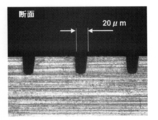
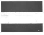
- FIGS. 8A and 8B show the state of the workpiece surface after grooving.
- the cutting groove could be formed without causing cracks on the workpiece.
- the blade 26 of the present embodiment when used, it is possible to perform stable and accurate cutting in the ductility mode without generating cracks, compared to the case of using the conventional electroformed blade. I confirmed that I can do it.
- FIGS. 9A and 9B show the results of Comparative Experiment 2 .
- 9A and 9B show the state of the workpiece surface after grooving, FIG. 9A shows the case where the blade 26 of the present embodiment is used, and FIG. 9B shows the case where the conventional electroformed blade is used. It is.
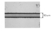
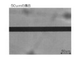
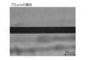
- FIG. 10A shows a case where the blade thickness is 20 ⁇ m
- FIG. 10B shows a case where the blade thickness is 50 ⁇ m
- FIG. 10C shows the case where the blade thickness is 70 ⁇ m.
- the blade thickness should be 50 ⁇ m or less, but in the case of SiC, with a 70 ⁇ blade thickness, there were small cracks but no significant cracks.
- Blade dicing equipment AD20T manufactured by Tokyo Seimitsu, AD20T is equipment model number
- Blade rotation speed 10000rpm
- Work feed speed (machining feed speed): 1mm / s -Depth of cut: 40 ⁇ m
- 11A and 11B show a workpiece surface (FIG. 11A) and a cross section (FIG. 11B) after grooving by the blade 26 of the present embodiment.
- ideal ductile mode processing can be performed even with a hard material such as cemented carbide.
- FIG. 12A and 12B show a work surface and a work cross section after grooving by the blade 26 of the present embodiment, respectively. As shown in FIG. 12A, a sharp cutting line is observed when viewed from the workpiece surface. As shown in FIG. 12B, it can be seen that a mirror cut surface was obtained even when compared with a conventional electroformed blade.
- FIGS. 13A and 13B show the state of the workpiece cross section after grooving, FIG. 13A shows the case where the blade 26 of the present embodiment is used, and FIG. 13B shows the case where the conventional electroformed blade is used. It is.
- each fiber tears each fiber, so that a clean cross section of the fiber cannot be observed, but with the blade according to the present invention, each fiber is entangled and not sharply broken. It is possible to obtain a cut surface having a proper fiber end surface.
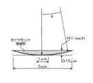
- a cut of 0.15 ⁇ m is made as a cut that does not cause a crack on the workpiece W by one cutting edge, and the removal amount at one time is 0.02 ⁇ m (20 nm).
- the critical cutting depth at which cracks such as SiC, Si, sapphire, and SiO 2 do not occur is on the order of submicron (for example, about 0.15 ⁇ m).
- the processing can be advanced by 0.314 mm (314 ⁇ m) in principle per blade rotation. If the dicing spindle is 10,000 rpm, 166 revolutions per second. Therefore, the cutting removal exclusion distance at the outer peripheral edge of the blade per second is 52.124 mm.
- the speed at which the workpiece material is processed and removed in the shearing direction is faster than the speed at which the workpiece material moves while being pushed.
- a minute cut is made to such an extent that the workpiece material does not break, and the workpiece material is machined in a horizontal direction perpendicular to the blade traveling direction, and then removed.
- the removed part becomes a form in which the blade advances.
- there is no room for incision of 0.1 ⁇ m or more enough to cause cracks so that it is possible to perform cutting in a ductile region based on plastic deformation without causing brittle fracture.
- ductility processing is performed by increasing the peripheral speed of the blade outer peripheral end (tip) due to blade rotation to the material to be processed compared to the feed speed of the blade to the material to be processed while rotating the blade at high speed. Is possible.
- the cross-sectional shape of the cutting edge portion 40 provided on the outer peripheral portion of the blade 26 is a double-sided taper type (both V-type) shown in FIG. 4B among the cross-sectional shapes shown in FIGS. 4A to 4C. Preferably used.
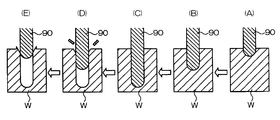
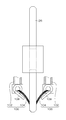
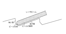
- FIG. 14 is an explanatory view schematically showing a state in which dicing is performed using a blade 26 having a double-side tapered type cutting edge portion 40.
- the tip end portion 40a provided at an arbitrary position of the cutting edge portion 40 of the blade 26 is the deepest portion (the bottommost portion) from the surface portion of the workpiece W, as shown from the (A) portion to the (C) portion in FIG.
- the workpiece W is ground while gradually moving to a point).
- the tip 40 a of the cutting edge 40 gradually moves from the deepest part of the workpiece W toward the surface.
- a gap S is formed between the side surface of the grinding groove and the side surface of the blade 26.
- the blade W is a cutting portion 60 where the workpiece W is ground on the upstream side in the blade rotation direction, while the blade side surface on the downstream side.
- a gap S is formed between the (side surface of the cutting edge portion 40) and the side surface of the groove, and the workpiece W is not ground, and the waste ground by the upstream cutting portion 60 is discharged into the groove. 62.
- burrs and chipping are generated by rubbing against the groove side when removing the blade from the material. For this reason, for example, as shown in FIG. 15, when a straight type blade 90 in which side surfaces on both sides are processed in a straight shape is used, the blade tip (cutting edge) enters the work W from the inside to the outside. The blade side constantly contacts the side of the cutting groove until it comes out. For this reason, as compared with the double-side tapered blade 26, the side surface of the cutting groove and the side surface of the blade are rubbed more easily when the blade tip part comes out of the workpiece W, and as a result, causes burrs and chipping (in FIG. 15). (D) part, (E) reference). In addition, when an electroformed blade in which diamond abrasive grains are embedded is used, the abrasive grains protruding from the blade side surface tend to scratch the groove side surface and facilitate the generation of burrs and chipping on the groove side surface.
- the blade 26 having the both-side tapered type cutting edge portion 40 when the blade 26 comes off from the workpiece W as described above, the gap S is generated between the blade side surface and the groove side surface. Therefore, no burr or chipping occurs. Moreover, the heat generated at the time of grinding can be discharged together with the chips as the chips are discharged. This makes it possible to prevent the blade 26 from warping.
- the workpiece W is cut until the cutting edge portion 40 of the blade 26 cuts into the workpiece W and reaches the lowest point, and then the blade 26 passes through the lowest point of the workpiece W. Since the blade 26 is pulled out from the workpiece W in a state where the gap S is formed between the blade side surface and the groove side surface in the extraction process, it is possible to effectively suppress the occurrence of chipping and the like.
- the size of the cutting edge (fine cutting edge) for making the cut is preferably a large abrasive grain size or cutting edge interval of about one digit.
- the cutting edge interval is 3 digits or more, it is difficult to make a fine cut in consideration of variations in the cutting edge interval.
- the maximum depth of cut is calculated geometrically when a flat sample is processed by moving a blade having cutting edges set at substantially equal intervals.
- the hatched portion is a chip portion per blade
- the AC length determined by the line connecting the blade center O and one point A on the chip is the maximum cut per blade. Depth g max .
- D is the blade diameter
- Z is the number of blade cutting edges
- N is the blade rotation speed per minute
- V S is the blade circumferential speed ( ⁇ DN)
- V W is the workpiece feed speed
- S Z is per blade
- the feed amount a is the depth of cut.
- g max Unit cutting edge per depth of cut
- lambda cutting edge spacing
- V omega work feeding speed
- V s blade speed
- a blade cutting depth
- D the blade diameter
- the interval between the cutting edges is important in order to keep the depth of cut per unit cutting edge below a certain level. Also, the rotational speed of the blade is important.
- a 2-inch blade (diameter 50 mm) is processed by rotating at 10,000 rpm, the workpiece thickness is 0.5 mm, the workpiece feed rate is 10 mm / s, and the blade outer periphery is cut.
- the edge spacing and formed at 1mm pitch V ⁇ : 10mm / s, V s: 157 ⁇ 10 4 mm / s, a: 0.5mm, D: 50mm, ⁇ : 1mm).
- the critical depth of cut by one blade is 0.08 ⁇ m, and still a depth of cut of 0.1 ⁇ m or less. Therefore, if the blade is not eccentric and ideally all cutting edges act on the workpiece removal processing, critically, if the cutting edge interval that can be formed on the outer periphery of the blade is 1 mm or less, it is fatal. It is possible to proceed the processing without giving excessive cuts that cause cracks.
- the critical depth of cut that does not cause cracks is about 0.1 ⁇ m.
- the critical cutting depth that does not cause the same crack is about 0.2 to 0.5 ⁇ m, so if the critical cutting depth is set to 0.1 ⁇ m or less, most brittle materials Can be processed within the plastic deformation region of the material without cracking.
- the cutting edge spacing around the blade is 1 mm or less.
- the interval between the cutting edges around the blade should be 1 ⁇ m or more. If the average cutting edge interval is 1 ⁇ m or less, that is, when the cutting edge interval is in the submicron order, the critical cutting depth amount and the material removal depth unit are approximately the same. That is, both are on the order of submicrons, but under such conditions, it is difficult to actually reach the removal amount expected by one cutting edge, and conversely, the machining speed is rapidly reduced by the clogging mode.
- the sample is a substantially flat sample
- the blade is rotated at a high speed
- the blade is set to a constant cutting depth with respect to the flat workpiece
- the content of the blade matches with the content of the blade that is cut while sliding the workpiece.
- the critical cutting depth given by one cutting edge depends on the cutting edge interval.
- the amount by which one cutting edge cuts affects the distance from the next cutting edge, and if there is a part with a large cutting edge interval in a certain part, it indicates the possibility of causing a cutting crack deeper than the desired critical cutting depth. . Therefore, the cutting edge interval is an important factor, and in order to obtain a stable cutting edge interval, a PCD material obtained by sintering single crystal diamond is preferably used so that the cutting edge interval is naturally set from the material composition. It is used.
- the abrasive grains even if the diameter of the diamond abrasive grains (average particle diameter) is large, the gap is closely packed, and if the substantial abrasive grain spacing is on the order of smaller than the grain diameter, the abrasive grains further It is possible to suppress and control the cutting.
- diamond abrasive grains having an ideal grain size of about 1 ⁇ m to 5 ⁇ m are desirable.
- the particle size is not necessarily the cutting edge interval.
- the interval between the cutting edges may correspond to the particle diameter, but the cutting edge interval is larger than the abrasive particle diameter in the state of being normally cut out and dressed.
- FIGS. 18A and 18B show photographs of the surface state. Since it is a sintered body, basically all the parts visible on the surface are composed of diamond as abrasive grains.
- the surface irregularities are formed from diamond grain boundaries, forming a natural irregular shape with approximately equal intervals.
- Each of these recesses acts as a cutting edge for cutting into the material.
- this cutting edge pitch has 260 and 263 peaks in the 4 mm range, so it can be seen that the cutting edge pitch is about 15 ⁇ m pitch.
- This material is composed of DA200 manufactured by Sumitomo Electric Hardmetal Co., Ltd., and the particle diameter of the composed diamond particles is nominally 1 ⁇ m. Thus, even if the particle size is small, the cutting edge interval is larger than that, and as shown in the figure, they are formed at substantially equal intervals.
- Such an equally spaced cutting edge is due to the blade itself being formed by a diamond sintered body made by sintering single crystal fine particles.
- the blade tip portion is greatly uneven to advance the workpiece.
- the blade side portion has a mirror-finished end surface after removal of the workpiece. Grind to be. For this reason, the blade tip is roughly formed to cut it, and the blade side is finely formed.
- the interval between the diamond abrasive grains is usually much larger than the grain size. This is because sparsely distributed diamond abrasive grains are simply plated, and are completely different at the time of plating.
- the diamond sintered body is very hard and has high strength because the sintering aid is melted in the diamond by sintering and the diamonds are firmly bonded to each other.
- the diamond sintered body has a relatively large diamond content compared to the electroformed blade (see, for example, JP-A-61-104045), and has a relatively high strength compared to the electroformed blade.
- the blade material since most of the blade material is occupied by diamond, it is possible to make the other part (including the sintering aid) smaller than the diamond volume. Even if the particle diameter is large, the gap of the diamond particle diameter can be made substantially on the order of microns.
- the recessed portions between the diamond abrasive grains play an extremely important role in the present invention.
- the diamond abrasive grains are very hard, some of the cobalt added as a sintering aid penetrates into the diamond, but some remains between the diamond abrasive grains. Since this portion is slightly softer than diamond, it is easily worn away during cutting and has a slightly recessed shape. That is, there is a portion sandwiched between diamonds, and by making the dent between them a minute cutting edge, it is intended to obtain a stable cut without giving an excessive cut.
- a fine cutting edge may cause not only a dent sandwiched between diamonds but also a dent portion formed by missing diamond particles itself to act as a cutting edge. This cutting edge interval may be set to an interval that does not exceed the critical cutting depth per blade shown in the previous equation.
- the diamond abrasive grains having a particle diameter of 25 ⁇ m are hardened by sintering.
- the diamond abrasive grains are 25 ⁇ m square cubes.
- the part of 1 ⁇ m on both sides outside of 25 ⁇ m is used as a bonding part for bonding with another particle. Then, it becomes a 27 ⁇ m square cube.
- the volume% that the diamond abrasive grain part fastens is about 78.6%.
- the gap between the diamond abrasive grains that is, the grain spacing will be substantially no more than about 1 to 2 ⁇ m.
- the part becomes a cutting edge (a minute cutting edge) for giving a cut.
- the particle interval is about 2 ⁇ m, even if particles having the pitch are pushed into the workpiece material at the particle interval, the displacement of the workpiece material is one digit or more smaller than the interval of the diamond abrasive grains. That is, 0.15 ⁇ m or less.
- cutting edges are formed at a pitch of 25 ⁇ m
- 6280 cutting edges are formed per approximately 157 mm in the entire circumference.
- 2093333 cutting edges can be applied per second.
- this one cutting edge makes a cut of 0.15 ⁇ m or less, and removes it by about 1/5 of 0.03 ⁇ m per second. If it does so, if it is 2093333 minute cutting blades, it will be possible to remove about 62799 ⁇ m per second, and theoretically it is possible to cut about 6 cm per second.
- the stable cutting amount can be set to 0.15 ⁇ m without giving an excessive cutting amount.
- the distance between the diamond abrasive grains is remarkably reduced as compared with the grain diameter of the diamond abrasive grains, and it is possible to accurately control the cutting amount.
- the cutting depth does not become larger than a predetermined initial cutting depth, and a stable cutting depth is constantly guaranteed during processing. As a result, it is possible to perform ductile mode cutting without error.
- the content of diamond abrasive grains can be further increased, and there is a content of about 93% (diamond content) if it is commercially available. If so, even more so, the proportion of sintering aid is reduced, i.e. the gaps between the diamond abrasive grains are actually very small.
- the cutting edge spacing is sufficient for performing ductile mode processing, but the blade thickness of the blade is 50 ⁇ m or less. In some cases, such large abrasive grains cannot be produced.
- the deformation of the work material accompanying the spread also extends in the vertical direction (cutting depth direction). That is, in consideration of the Poisson's ratio of the workpiece material, it is necessary to make the cut width finite to some extent. This is because if the cut width is extremely increased, the deformation aftermath also extends in the longitudinal direction due to material deformation due to the influence of the Poisson's ratio. This is because a cutting amount exceeding the predetermined critical cutting depth is entered, and as a result, cracking of the workpiece W may be induced.
- the blade thickness (blade width) of the blade that can stably give a cut when considering the influence of the Poisson's ratio is examined.
- Table 4 shows the relationship between the Young's modulus and Poisson's ratio of the brittle material.
- the tip of the thin straight blade is not particularly sharpened arbitrarily, and when it is always processed, the cross-sectional shape becomes a substantially semicircular shape.
- the blade radius at the tip is about 25 ⁇ m, and the apex angle giving the 5 ⁇ m width cut is about 12 degrees.
- the cutting edge basically acts more locally than the above state, so the width of the cutting edge basically affects the cutting depth. It can be cut stably without affecting.
- the width of the blade is also related to the buckling strength of the blade itself, although there is a viewpoint in performing the ductile mode processing.
- the width of the blade is also limited by the workpiece thickness.
- WORK is generally supported by dicing tape. Since the dicing tape is an elastic body, unlike a hard material such as a workpiece, the dicing tape is easily displaced in the vertical direction (Z direction) with a little stress. Here, when the workpiece is cut with a blade, the cross-sectional shape of the portion to be cut in the workpiece, the hatched portion shown in FIG. 20A becomes important.
- the portion in contact with the blade is a horizontally long rectangle as shown in FIG. 20B.
- the cross-sectional portion to be removed is a horizontally long rectangle
- the maximum displacement of the bending is as follows. (Actually, it is a bending of the plate, but it is simply a problem of the beam and it is assumed that the distributed load is acting.)
- the maximum deflection is inversely proportional to the cube of the workpiece thickness h and proportional to the fourth power of the blade contact area l at the center of the beam.
- the blade thickness must be smaller than the thickness of the target workpiece as shown in FIG. 20C.
- the width of the blade must naturally be 50 ⁇ m or less.
- the workpiece does not bend in the contact area.
- a stress that bends or compresses in the contact area works, but the work is a dense continuous body in the lateral direction, and deformation is restricted by the Poisson's ratio. Therefore, it locally acts on the stress applied from the blade as a reaction force from the workpiece, and as a result, it is possible to perform processing with a predetermined cut without generating cracks.
- the film thickness unevenness at the time of film formation corresponds to the blade thickness unevenness as it is.
- the film formation surface itself is an innocent surface, it may be in contact with the side of the material completely to induce frictional heat, and there may be a subtle swell, which may break the material.
- the blade 26 of the present embodiment is integrally formed of a diamond sintered body sintered using a soft metal sintering aid, the blade outer peripheral end portion and the blade side surface portion are subjected to wear treatment. It becomes possible to mold with. Particularly, since the outer peripheral edge of the blade is a cutting edge, as described above, it is possible to further change the wear processing conditions in order to obtain a predetermined cutting edge.
- the role of the blade side surface is primarily to eliminate chips.
- the contact with the workpiece side surface is not excessively contacted but stable. It is desirable that the side surface is roughened to the extent that it is finely cut.
- any of the techniques described in the cited documents is impossible in that a desired surface state can be designed in accordance with the state of the outer peripheral end of the blade and the side surface of the blade, respectively, and such a surface can be manufactured.
- blades used in scribing are not suitable for processing in the ductile mode for the following reasons.
- the minute cutting edge does not function as a cutting edge that gives a scribing crack.
- the blade material In order for the blade to cut a certain amount into the workpiece and proceed as it is, the blade material needs to have high strength against the workpiece material. If the blade material is simply made of a material that is soft with respect to the workpiece material, that is, a material with a low Young's modulus, the workpiece material is If the member has a high elastic modulus, the surface of the work cannot be deformed minutely, and if it is forced to deform it, the blade itself will buckle. As a result, processing does not proceed.
- the buckling load P of the long column supported at both ends is given by the following equation.
- E Young's modulus
- I sectional moment of inertia
- l length of long column (corresponding to blade diameter).
- a cross-sectional second moment that does not cause buckling deformation is required, specifically the blade thickness.
- the blade thickness Must be thickened. However, particularly when a brittle material is processed and the blade thickness is greater than the workpiece thickness, the workpiece material surface is deformed and cracked. Therefore, the blade thickness must be thinner than the workpiece thickness.
- the blade material must have a higher elastic modulus than the workpiece material.
- Such a relationship corresponds to a difference between the conventional electroformed blade and the blade 26 of the present embodiment. That is, the electroformed blade is bonded with a bonding material such as nickel and is made of nickel as a material.
- the Young's modulus of nickel is 219 GPa, but for example SiC is 450 GPa.
- the diamond abrasive grains electrodeposited on nickel themselves are 970 GPa, they exist independently, and as a result, are governed by the Young's modulus of nickel.
- the blade thickness since the work material is highly elastic, the blade thickness must be increased incidentally. As a result, it is necessary to increase the contact area by increasing the thickness of the electroformed blade, thereby inducing cracks and cracks.
- the Young's modulus of the diamond sintered body is equivalent to 700 to 800 GPa because diamonds are bonded to each other. This is almost comparable to the Young's modulus of diamond.
- the elastic modulus of the blade 26 is larger than the elastic modulus of the workpiece W
- the surface on the workpiece W side, not the blade 26, is deformed. While the workpiece W side is deformed, it is possible to cut and remove the workpiece as it is.
- the blade 26 does not buckle and deform in the process. Therefore, even a very sharp blade 26 can be processed without buckling.
- Table 5 shows the Young's modulus of each material. As is apparent from Table 4, the diamond sintered body (PCD) has a significantly higher Young's modulus than most materials such as sapphire and SiC. For this reason, even a blade thinner than the workpiece material thickness can be processed.
- PCD diamond sintered body
- the hardness of the blade material is lower than the hardness of the workpiece material, for example, in the case of an electroformed blade, diamond is supported by soft copper or nickel.
- the surface diamond abrasive has a very high hardness, but the hardness of nickel under which the diamond abrasive is supported is extremely low compared to diamond. Therefore, when an impact is applied to the diamond abrasive grains, the nickel underneath absorbs the impact. As a result, the hardness of nickel is dominant in the case of electroformed blades. As a result, even if hard diamond abrasive grains collide with the workpiece material and attempt to cut the workpiece, the binder absorbs the impact. Therefore, it is difficult to give a predetermined cut as a result.
- the processing does not proceed unless a blade rotation speed of a certain level or more is given to the diamond.
- a blade rotation speed of a certain level or more is given to the diamond.
- the diamond sintered body has a hardness comparable to that of a diamond single crystal, and is much higher than a hard and brittle material such as sapphire or SiC.
- a cutting edge micro-cutting edge
- the impact acts on the micro-cutting blade portion as it is, and sharp Combined with the tip portion, it is possible to accurately remove and process a very small portion.
- the blade surface (surface perpendicular to the rotation axis of the blade 26) is the normal direction (blade normal direction) as a method of cutting the outer peripheral edge of the blade using laser light (pulse laser). ) To form a cutting edge.
- the outer peripheral edge of the blade has a scooping surface and a flank surface.
- Cutting edges are continuously formed along the circumferential direction, and stable machining can be realized.
- FIGS. 27A and 27B are schematic views showing a difference between a conventional grindstone and a grindstone cutting edge by a blade according to the present invention.
- a conventional general grindstone is composed of abrasive grains and a binder.
- the blade according to the present invention (PCD blade) was integrally sintered with 80% or more (for example, about 90%) of diamond abrasive grains and a very small amount of sintering aid. Consists of uniform PCD material.
- PCD has generally been used as a cutting tool, but in the present invention, the uniform PCD surface is arbitrarily scribed with a pulse laser, and the cutting edges are arbitrarily formed at equal intervals, thereby enabling ductility. It functions as a grindstone that performs mode machining. Since the cutting edge can be set independently irrespective of the abrasive grain size, it is completely different from the concept of a conventional abrasive grain count in which the cutting edge size is the same as the abrasive grain size.
- diamond abrasive grains are graphitized at 600 ° C., for example, the melting point of nickel in the binder is 1455 ° C., and the melting point of oxidized nickel is 1900 ° C. At that time, the diamond abrasive grains are graphitized, but the nickel remains oxidized and sometimes covers the hard diamond abrasive grains inside.
- the principle is such that the binder is removed and new abrasive grains are generated, and the laser irradiation itself does not belong to the principle of forming a cutting edge.
- the surface thus formed is not basically formed with a cutting edge interval by laser light. This is because even if the laser beam is irradiated with a certain period, the uneven protrusions formed at the irradiated pitch do not have diamond abrasive grains and do not function as a cutting edge. Simply, the binder is scraped off to make it easier to produce new diamond abrasive grains.
- the cutting edge interval has a shape that depends on the abrasive grains and concentration of the underlying diamond and is not related to the pulse period of the laser beam. That is, the interval between the laser marks due to the pulse interval of the laser beam does not become the interval between the cutting edges.
- This is a completely different principle from dressing a blade (PCD blade) according to the present invention by dressing by laser light irradiation to form a cutting edge, and the surface binder is simply melted by Joule heat by laser light irradiation.
- the unevenness formed at the pulse interval of the laser beam is not used as a cutting edge.
- FIG. 29 shows the situation at this time.
- some of the diamond abrasive grains that make up the blade remain graphitized, but this is physically fragile and easily peels off during processing.
- a certain diamond abrasive works.
- a sharp shape with a ridge line that is substantially perpendicular to the direction of movement of the blade with respect to the workpiece is formed on the outer peripheral edge of the blade (surface of the grindstone).
- the ridge portion is mostly formed of diamond abrasive grains.
- a scooping surface and a flank surface are formed with a ridge line as a boundary with respect to the moving direction of the blade, and this corresponds to a cutting edge.
- the cutting blade interval can be adjusted by changing the pulse period of the laser beam or the rotation speed of the blade.
- the cutting amount of one cutting edge and the cutting edge interval are changed depending on the normal count (abrasive grain size) and the degree of concentration.
- an arbitrary parameter can be obtained by adjusting the parameters corresponding to the count and the concentration by the pulse frequency, output, and pulse width of the laser beam.
- the cutting edge size of the form can be configured. This means that the cutting of each workpiece can be freely set with one material (PCD blade) for each workpiece.
- TDC-HM80 and TDC-GM80 manufactured by Tomei Dia Co., Ltd. among products made by sintering more than 70 vol% diamond abrasive grains, and these materials can also be used suitably.
- the abrasive distribution in the case of electroforming in grinding can be set on the cutting edge on the average, but cannot be adjusted locally due to the density of the abrasive distribution.
- the formation of the cutting edge by the laser beam is an essential condition for realizing the ductile mode processing as described above.
- Theoretically forming the cutting edges at equal intervals along the circumferential direction at the outer peripheral edge of the blade as theoretically even in a local location leads to precise control of the cutting amount of one cutting edge, and the ideal ductility mode Processing can be realized and mirror processing can be performed.
- FIG. 30 As a method of performing cutting edge attachment to a braid
- FIG. 31 shows a state of cutting edge and flank wear by laser light (pulse laser).
- the method of forming the cutting edge by irradiating the laser beam from the blade normal direction has the following problems when used stably over a long period of time. became.
- the first problem is that the hole diameter changes between the entrance side and the exit side of the laser beam. As shown in FIG. 31, the hole diameter inevitably increases on the entry side, and the hole diameter tends to decrease on the exit side. In this case, the machining corresponds to the difference in cutting resistance between the incident side and the exit side of the laser beam, and the workpiece W is likely to crack.
- the second problem is that the cutting edge wears quickly.
- the space between the cutting blade remains flat (see FIG. 23). At that time, it will be rubbed with the work and easily worn out.
- the chips at the cutting edge portion are caught as they are, but they enter the flat portion and further wear of the tip portion is accelerated.
- wear of the tip portion without a hole is accelerated before use (photo on the left side of FIG. 31) and after use (photo on the right side of FIG. 31).
- the wear of the tip portion without a hole before and after use progresses rapidly and is shining with wear. This corresponds to flank wear, and since there is no flank, the flank portion is worn away.
- laser light is incident from a direction parallel to the blade surface (blade tangential direction), that is, laser light is incident along the traveling direction of the blade to be processed,
- a cutting edge having a scooping surface and a flank surface is continuously formed along the circumferential direction of the outer peripheral edge of the blade.
- the portion irradiated with the laser beam becomes a scooping surface by putting the laser beam in the blade tangential direction, and the laser beam on the way has passed.
- the part becomes a flank.
- a scooping surface and a flank surface are formed in the blade surface, and a ridge line is formed between them to form a shape corresponding to a cutting edge.
- a ridge line with a constant interval is formed at the outer peripheral edge of the blade formed in this way, and the formation of the scooping surface and the flank surface with the ridge line as a boundary itself is from the side of the blade surface, that is, the normal direction of the blade surface
- the effect is completely different from the method formed by laser irradiation. In order to make a predetermined cut stably, it is very important that a flank is formed.
- the scooping surface and the relief surface can be formed cleanly.
- the incident tip of the beam contributes to the formation of a scooping surface
- the side surface portion of the beam contributes to the formation of a flank.
- the crawl angle is a small negative angle, so that an elevation angle is made incident on the blade surface at a low angle and a sharp crawl surface is formed. That is, it is possible to form a scooping surface and a flank surface by utilizing the characteristic of straight beam traveling.
- the cutting edge is attached by irradiating the laser beam from the blade tangential direction instead of the blade normal direction, the cutting edge having a scooping surface and a flank surface at the outer peripheral edge of the blade Can be formed continuously.
- FIG. 34 shows the result of cutting by irradiating laser light from the blade tangential direction.
- a cutting edge having a scooping surface and a flank surface is formed on the outer peripheral edge of the blade by irradiation of laser light from the blade tangential direction. Therefore, since the newly processed edge portion acts as a cutting edge as it is, it is possible to sharpen the grindstone by periodically cutting the edge.
- a mode in which the laser beam is irradiated through the cylindrical lens is more preferable.
- FIG. 35 shows a result of irradiating a diamond sintered body (flat plate sample) with a laser beam through a cylindrical lens.
- the laser processing conditions at this time are as follows.
- the grooves serving as cutting edges are preferably formed at a fine pitch in a direction perpendicular to the blade traveling direction.
- the groove pitch interval is about 10 ⁇ m with respect to the groove width of 80 ⁇ m.
- the blade width may be formed so that the ridge line is substantially perpendicular to the blade traveling direction by blade rotation with respect to the outer peripheral end portion of the blade of 50 ⁇ m.
- FIG. 36 is a view showing a state where a cutting edge is formed at the outer peripheral edge of the blade using a cylindrical lens, and is a view seen from a direction parallel to the blade surface. As shown in FIG. 36, when a large number of steep ridge lines are formed at the outer peripheral edge of the blade, each end face can be a cutting edge and act on the workpiece. As a result, ideal ductile mode processing can be performed.
- the same principle can be used not only for the dicing blade but also for the surface grindstone with the same principle as described above. That is, as shown in FIG. 37, the laser beam is irradiated at an angle so as to strike from the front in the traveling direction of the rotating flat grindstone. As a result, a ridge line is formed in a direction perpendicular to the traveling direction of the grindstone, and a scooping surface and a flank surface are formed. By irradiating this with a constant pulse while keeping the rotation speed of the flat grindstone constant and controlling the pulse width, the cutting edge interval can be controlled. Stable ductile mode grinding can be performed by adjusting the cutting edge interval so that the cutting amount of one cutting edge does not crack the workpiece.
- the surface form of the diamond sintered body obtained by laser light irradiation acts as a cutting edge as it is, and plays a role as a grindstone.
- the diamond sintered body itself is roughened with a laser beam to form a scooping surface and a flank surface, and the roughness itself formed on the surface functions as a cutting edge.
- a grindstone has been considered in the form of an abrasive grain count by changing the cutting edge size depending on the grain size of the abrasive grains.
- the cutting edge size depends on the laser irradiation interval
- the particle size of the abrasive grains contained in the grindstone is irrelevant. That is, there is no concept of abrasive count.
- the diamond sintered body 80 having a diamond abrasive grain 82 content of 80% or more is integrally formed in a disk shape, and the outer periphery of the blade 26 has a diamond.
- a cutting blade portion 40 is provided in which cutting blades (micro cutting blades) formed of concave portions formed on the surface of the sintered body 80 are continuously arranged along the circumferential direction. For this reason, it becomes possible to control the cutting depth (cutting amount) of the blade 26 with respect to the workpiece W with higher accuracy than the conventional electroformed blade. Accordingly, the workpiece W can be moved relative to the blade 26 while giving a constant cutting depth to the workpiece W without being given excessive cutting.
- the concave portion formed on the surface of the diamond sintered body 80 functions as a pocket for conveying chips generated when the workpiece W is processed.
- emission property of a chip improves, it becomes possible to discharge
- the diamond sintered body 80 has a high thermal conductivity, heat generated during the cutting process is not accumulated in the blade 26, and there is an effect of preventing an increase in cutting resistance and warping of the blade 26.
- the rotation direction of the blade 26 is preferably the down cut direction. That is, when the workpiece W is moved relative to the blade 26 while giving a cut to the workpiece W, as shown in FIG. 14, the rotational direction in which the cutting edge of the blade 26 cuts into the workpiece surface.
- An embodiment in which dicing is performed while rotating the blade 26 is preferable.
- dents are formed in the grain boundary portion between diamond particles.
- the recessed portion acts as a cutting edge.
- the cutting edge is formed by unevenness due to the naturally formed roughness, and particularly the cutting edge is formed in the concave portion.
- the action of the outer periphery of the blade is to remove the chips while the cutting edge acts mainly to cut the cutting edge into the workpiece and further advance it.
- a new side surface has just appeared on the workpiece side, and a very active surface appears depending on the workpiece material.
- the active surface tends to interact with other materials, and may stick to a diamond sintered body that is a blade material in particular. In order to prevent this, it is necessary to consider the lubrication between the blade side surface and the workpiece material immediately after the blade tip is removed.
- the action of fine particles on the side surface of the blade made of sintered diamond plays a large role as an effect of improving the lubrication effect between the blade and the workpiece.
- the sintered diamond When fine particles are allowed to act on the side surface of a blade made of sintered diamond, as described above, the sintered diamond has a concave portion on the grain boundary portion or the uneven surface made of natural roughness. Has a lot. Fine particles are taken into the dent. When processing while the blade side surface is rubbed against the workpiece, the fine particles accumulated in the recessed portion formed of the diamond sintered body jump out and continuously roll between the blade side surface and the workpiece side surface. This continuous rolling of the fine particles is called a “bearing effect”, which prevents the blade and the workpiece surface from biting and forms a lubricating effect between the blade and the workpiece.
- this lubrication effect is not limited to simply preventing the biting between the blade and the workpiece.
- the bearing effect of the fine particles is that the rolling fine particles have a function of polishing the side surface of the workpiece.
- the workpiece side surface is polished.
- the workpiece side surface is cleanly mirror-finished without leaving a grinding streak that is simply ground with fixed abrasive grains. Can be formed.
- Such lubrication effect is such that when grooves are formed on both sides of the blade along the rotation, the fine particles easily roll, that is, a bearing effect appears.
- a fine V-shaped groove may be cut in the side surface at the cross section where the blade enters the workpiece. Then, the fine particles enter between the V grooves, and roll along the V grooves as the blade rotates. As a result, fine particles roll along the V-shaped groove between the workpiece material and the blade, and a bearing effect appears.
- the fine particles are different from the fixed abrasive grains and the individual fine particles change their direction to some extent and act randomly, so there is no unidirectional grinding streak left and the work material side surface has a polishing effect. Demonstrated. As a result, it is possible to obtain a mirror surface from which grinding streaks are removed.
- the fine particles are solidified by firing in advance, and the fine particles are spilled from the surface of the blade formed by the solidified fine particles, and the spilled fine particles are formed on the side of the blade. You might recall a blade that rolls and mirrors.
- the blade in which the rolling microparticles are fired on the blade surface in advance, as the processing proceeds, the blade gradually becomes thinner as the microparticles fall off. That is, a stable and constant groove width cannot be formed. In addition, it becomes difficult to continue supplying fine particles stably and continuously.
- the fine particles are supplied while the blade side surface is continuously worn.
- the concave portion for storing the fine particles is stably configured. It is difficult to do this, and the recessed portion cannot be formed of diamond with high hardness. Further, it is not possible to supply a blade having arbitrary irregularities with high rigidity of the blade member itself.
- the critical cutting depth of the abrasive grain cannot be controlled when the binder forming the reference plane is removed. Therefore, a fatal crack is exerted on the workpiece side.
- the side surface of the workpiece may be mirror-finished even if there is no dent in some cases, but the fine particles may act on the blade side surface to develop a polishing effect.
- grinding side marks still remain on the side surface of the workpiece, and potential cracks due to protrusions enter.
- the effect of fine particles that mirrorize while rolling becomes meaningless when used in combination with a processing phenomenon that causes brittle fracture while causing cracks.
- the protruding diamonds are scattered in the plane. That is, there is no dent portion where fine particles accumulate on the side surface of the blade.
- the dent portion formed of a metal material such as nickel has a lower hardness than the material used for the fine particles. Even if the fine particles come out from the concave part, the concave part where the periphery is formed of a metal material such as nickel does not have the function of the concave part as a cutting edge. Only the blade side of the soft metal such as nickel is worn, while there is almost no effect of polishing and removing the workpiece. As a result, the effect of polishing the workpiece cannot be expected simply by gradually removing the blade itself.
- the binding material of the blade When the binding material of the blade is worn by fine particles, it means that the blade thickness changes even during the processing due to the polishing removal action on the binding material by the fine particles.
- the groove width is strictly controlled in grooving or the like, it cannot be used at all in the process of wearing the blade as it is seen, and it does not make sense as a blade to be machined.
- a blade composed of a diamond sintered body as in this embodiment, first, it is composed of a diamond sintered body as a premise. Further, the diamond content is desirably 80% or more.
- the fine particles are accumulated in the concave portion of the sintered body against the blade composed of the diamond sintered body, and roll with the fine particles coming out by rubbing against the work from there. Since the periphery of the recess is made of diamond, fine particles act on the edge of the recess made of diamond to polish the workpiece.
- the dent part is selectively removed by friction to form a dent, but the non-dent part is conversely diamond-rich and is usually more than the work material. Hardness increases. Therefore, the fine particles coming out of the recessed portion are supported by the high-hardness diamond at the edge portion of the recessed portion, and the fine particles roll and act on the edge composed of the high-hardness diamond. As a result, a polishing pressure is applied to the workpiece side to efficiently polish the workpiece.
- the method for supplying the fine particles is not particularly limited as long as the above-described effects can be obtained.
- the following methods (first to third examples) can be preferably employed. .
- fine particles such as WA white alumina abrasive grains, GC green carborundum abrasive grains, and diamond abrasive grains are preferably used.
- Fine particles having various particle diameters of about 0.01 ⁇ m to 10 ⁇ m may be used. What is necessary is just to optimize a particle size and the material of the fine particle to be used suitably according to a workpiece
- fine particles are used as a powder as they are, fine fine particles are blown off by the wind pressure of a blade that rotates at high speed. Therefore, it is preferable to use fine particles suspended in a liquid.
- the suspending solvent water is an example of the simplest liquid, but it may be suspended in ethanol or IPA in order to efficiently attach fine particles to the blade surface.
- lubricating oil such as wrapping oil may be used.
- the solvent for suspending the fine particles is preferably optimized depending on the characteristics of the workpiece. Even if wrapping oil or the like is used, it is supplied only to the blade and not directly to the workpiece.
- the liquid containing fine particles supplied to the blade acts only on the cut surface of the workpiece and does not act on the workpiece surface. Therefore, from the viewpoint of the work, heat generation is prevented by the lubrication effect and no special liquid is supplied to the work surface. Therefore, in a conventional wet environment, a workpiece that wets the chip on the surface and destroys the element can be processed as if it were dry processing.
- ⁇ It is desirable to put the place where the liquid is applied just before the blade cuts into the workpiece. Since the blade rotates at a high speed and a part of the blade is blown away by the centrifugal force, it is desirable that the blade is just before entering the workpiece.
- the liquid containing no fine particles has low viscosity, and by including fine particles, the interfacial tension between the fine particles and the liquid acts to increase the binding force, and as a result, the viscosity can be increased as a whole. If the viscosity can be increased, even if it is applied to the blade, the liquid containing fine particles will not be blown off by the centrifugal force of the blade, and it is possible to efficiently apply the liquid containing fine particles to the side or tip of the blade. is there.
- the slurry when supplying a liquid slurry along the workpiece, the slurry does not adhere to the workpiece, but the viscosity needs to be low enough to flow along the workpiece.
- the slurry is blown away when the slurry contacts the blade rotating at high speed.
- the concave portion is very small, and when the fine particles are effectively taken into the pocket of such a portion, the wind pressure and centrifugal force of the blade are dominant, and the fine particles stay on the blade. It may be difficult to do.
- the fine particles are suspended in a liquid, and the suspension is applied to the blade side surface.
- a capillary structure such as a brush
- the liquid is applied to the blade solid rotating from the solid on the principle of the liquid capillary, the liquid is supplied, leaving the fine particle component contained in the liquid, A method of causing fine particles to act on the blade is conceivable.
- the viscosity increases, the surface tension increases, and the gel can be formed.
- a liquid enters between the fine particles, and the surface tension can be increased.
- the fine particle supply mechanism shown in FIGS. 24 and 25 can be preferably employed.
- the blade 26 is surrounded by a flange cover 100 fixed to the spindle 28 (see FIG. 1) side, and a liquid supply pipe as a liquid supply means attached to the flange cover 100 portion.
- a supply mechanism 106 including a capillary structure member 104 that receives supply of a liquid containing fine particles from the liquid supply pipe 102 and transfers the supplied liquid containing fine particles to both side surfaces of the blade 26 by capillary action. Is arranged.
- the capillary structure member 104 either a brush-like member, a brush-like member or a foam member is used. That is, a structural member in which small spaces are continuously present in the gap is used.
- the capillary structure member 104 is slightly bent between the lower end portion of the liquid supply tube 102 and the peripheral side surface of the blade 26, and the blade structure from both sides so that the tip thereof follows the rotation direction of the blade 26. 26 is in contact with both circumferential side surfaces.
- the capillary structure member 104 is formed to have a required width in order to uniformly apply a liquid containing fine particles to the peripheral side surface of the blade 26.
- a guide member 108 made of a rigid material is provided at the lower end portion of the liquid supply tube 102 to guide the tip end portion of the capillary structure member 104 to the peripheral side surface of the blade 26.
- a constituent material such as a brush-like member or a brush-like member as the capillary structure member 104
- a soft linear member such as a polyester wire or cotton fiber can be suitably used. If a soft linear member or the like is used, even if it contacts the side surface of the blade 26 rotating at high speed, the side surface of the blade 26 is not excessively damaged.
- the capillary structure member 104 is guided to the peripheral side surface of the blade 26 by the guide member 108 made of a rigid material by guiding the tip portion of the capillary structure member 104.
- the liquid blows off on the blade, and as a result, the fine particles cannot act on the blade efficiently.
- the fine particles can be efficiently supplied along the side surface of the blade.
- ⁇ Since it is only applied to the blade, it does not cool down, such as splashing water on the workpiece.
- the workpiece can be processed dry only by applying a small amount of liquid to the blade.
- the fine particles when the fine particles come out of the dent, the fine particles are rolled between the edge of the dent formed by the diamond particles below and the work piece, so that the fine particles rolling on the work are surely cut.
- the workpiece can be reliably polished while being given.
- high-concentration fine particles are suspended in a small amount of water in advance in a portion where the blade advances, and the fine particles adhere to the portion where the blade advances in a thin line shape.
- attaching it may be extruded and attached with a syringe or the like.
- high-density fine particles are applied in advance on a thin sheet. Affixed on the substrate to be cut or grooved.
- the work W placed on the work table 30 is held and fixed in a state of being vacuum-sucked by a porous chuck (porous body) constituting the work table 30.
- the work W holding method is not limited to the vacuum suction method, and any means may be used as long as the work W can be fixed uniformly over the entire plane. Then, after the entire back surface of the flat workpiece W is held and fixed by vacuum suction, dicing is performed using the blade 26 of the present embodiment.
- the blade 26 of the present embodiment large irregularities are formed on the outer peripheral edge of the blade, while the side surface of the blade can be constituted only by the fine roughness of the diamond sintered body. Therefore, the blade side surface does not excessively cut the workpiece side surface.
- the dicing process is performed using the blade 26 in a state where the workpiece W is bent so that the surface of the workpiece W into which the blade 26 is cut is convex toward the blade 26 side. Is preferred.
- a mode in which the work table 30 that holds and fixes the work W by vacuum suction is curved and deformed can be employed.
- a method of bending the work table 30 for example, a method disclosed in JP 2012-119670 A can be suitably used.
- the above description shows a blade integrally formed in a disk shape by a diamond sintered body formed by sintering diamond abrasive grains.
- a sintered body (PCBN: Poly-crystalline Boron Nitride) using CBN abrasive grains can be suitably used instead of diamond abrasive grains.
- PCBN is manufactured by almost the same manufacturing method as PCD. That is, PCBN abrasive grains are placed in a pressure vessel and baked at a high temperature and high pressure to complete PCBN as in PCD.
- Sumiboron manufactured by Sumitomo Electric Hardmetal Co., Ltd. is a general-purpose product as a sintered PCBN.
- Sumiboron BNC200 and BNC300 contain 80% or more of CBN, have the same configuration as PCD, and have the second highest hardness after PCD. (PCD is about Hv8600, CBN is about Hv5000) (Hv is Vickers hardness) Thermal conductivity is 1000 W / mK in PCD, but PCBN also has thermal conductivity of 200 W / mK.
- DBW85 contains 85% CBN abrasive grains
- AMB90 contains 90% CBN abrasive grains
- DBS900 contains 90% CBN abrasive grains.
- a whetstone containing these CBN abrasive grains in a proportion of 80% or more and sintered at high temperature and high pressure has the same characteristics as PCD in the action of a cutting edge for performing ductile mode processing.
- PCBN is made into a sintered body
- CBN abrasive grains are closely bonded together, and the grain boundary portion between the abrasive grains becomes a cutting edge.
- the end portion is composed of a continuous and uniform diamond sintered body, and ridge lines with continuous and constant intervals are formed at the outermost peripheral end of the blade with respect to the traveling direction with respect to the workpiece.
- a grindstone blade having a flank formed thereon.
- the diamond sintered body is formed in a circular shape as a single piece, rather than being separated into individual pieces by first having an outer peripheral end that is continuous in a disk shape or an annular shape. For this reason, the temperature distribution during processing becomes an axisymmetric temperature distribution. As a result, the flatness of the flat surface formed by the portion corresponding to the cutting edge of the tip portion is improved without being disturbed, and acts on a straight line even when the blade rotates.
- the outer peripheral edge is composed of a uniform diamond sintered body. From this, it becomes possible to form cutting edges with arbitrary intervals by performing processing with periodicity on the diamond sintered body (processing with pulse laser is available as processing with periodicity). .) Conventionally, in order to change the cutting edge of the grindstone, the acting cutting edge size was changed by changing the abrasive grain size to be configured. By forming the cutting blades with the interval and size, it is possible to form irregularities with a pitch that is not related to the abrasive grain size, and this functions as a cutting blade.
- Appendix 2 The grindstone blade according to appendix 1, wherein the grindstone blade has a volume content of diamond of 70% or more.
- the pulse laser that forms the cutting edge at the outer peripheral edge of the grindstone blade is formed by irradiating at a predetermined angle between 0 ° and 90 ° from the tangential direction of the outer periphery at the blade outer peripheral end parallel to the blade surface.
- the grindstone blade according to appendix 5 which is characterized.
- the pulse laser that forms a cutting edge at the outer peripheral edge of the grindstone blade is characterized in that the laser beam is cut in an elliptical shape from the tangential direction of the outer periphery parallel to the blade surface and at the outer peripheral edge of the blade.
- the grinding wheel blade according to appendix 5.
- DESCRIPTION OF SYMBOLS 10 ... Dicing apparatus, 20 ... Processing part, 26 ... Blade, 28 ... Spindle, 30 ... Worktable, 36 ... Annular part, 38 ... Mounting hole, 40 ... Cutting blade part, 42 ... Diamond abrasive grain, 44 ... Spindle main body, 46 ... spindle shaft, 48 ... hub flange, 80 ... diamond sintered body, 82 ... diamond abrasive grains, 84 ... cutting edge (fine cutting edge), 86 ... sintering aid
Landscapes
- Engineering & Computer Science (AREA)
- Mechanical Engineering (AREA)
- Polishing Bodies And Polishing Tools (AREA)
- Dicing (AREA)
- Finish Polishing, Edge Sharpening, And Grinding By Specific Grinding Devices (AREA)
Abstract
脆性材料から構成されるワークに対しても、クラックや割れを発生させることなく、延性モードで安定して精度良く切断加工を行うことができるダイシング装置及びダイシング方法を提供する。ワークを切断加工するダイシング装置において、ダイヤモンド砥粒を焼結して形成されたダイヤモンド焼結体(80)によって円盤状に構成され、外周部の周方向に連続した微小切れ刃を有するダイシングブレード(26)と、ダイシングブレード(26)を回転させるスピンドル(回転機構)と、ダイシングブレード(26)によってワークに切り込み深さを与えながら、ワークをダイシングブレード(26)に対して相対的に移動させる移動機構と、を備える。
Description
本発明は、半導体装置や電子部品が形成されたウェーハ等のワークに対して切断や溝入れなどの切断加工を施すダイシング装置及びダイシング方法に関する。
半導体装置や電子部品が形成されたウェーハ等のワークを個々のチップに分割するダイシング装置には、少なくともスピンドルによって高速に回転されるダイシングブレードと、ワークを載置するワークテーブルと、ワークテーブルとブレードとの相対的位置を変化させるX、Y、Z、θの各移動軸が設けられており、これらの各移動軸の動作によってワークに対して切断や溝入れなどの切断加工を施す。
このようなダイシング装置で用いられるダイシングブレードとしては、これまでに各種提案されている(例えば、特許文献1、2参照)。
特許文献1には、ダイヤモンド砥粒をニッケルや銅等の軟質の金属との合金を結合材として、電気メッキ技術を用いた電鋳法で金属母材(アルミフランジ)の端面に固着させた電鋳ブレードが記載されている。
特許文献2には、化学気相蒸着(CVD)法によって硬度が互いに異なるダイヤモンド層を順次積層することにより、複数のダイヤモンド層からなる基材により構成されるダイヤモンドブレードが記載されている。
ところで、近年、半導体パッケージの小型化、高集積化への要求が高まっており、半導体チップの薄片化が進んでいる。これに伴って、例えば厚さ100μm以下の極薄のワークが要求されるようになってきている。このような極薄のワークは非常に割れやすいので、極薄のワークをダイシングする場合には、ダイシングブレードによって形成される切断溝の溝幅をできるだけ細くする必要がある。例えば、厚さ100μm程度のワークを切断加工する際は、ダイシングブレードの刃厚として、ワークの厚みよりも薄くする必要があり、少なくとも100μm以下の厚みとする必要がある。仮にワークの厚みよりも厚い刃厚のダイシングブレードで切断加工を行った場合、ワークが切断される以前に割れてしまうことがある。このため、例えば、厚さ50μm程度のワークに深さ30μm程度の溝入れ加工を行う場合には、当然のことながら、溝の幅も30μm以下にしなくてはならないため、ダイシングブレードの刃厚を30μm以下に抑える必要がある。
しかしながら、従来のダイシングブレードには以下に示す技術的な問題があり、極薄のワークに対して安定して精度良く切断加工を行うことができない。
また、脆性材料については、割れの原因となるクラックを回避することが難しい。銅やアルミニウム及び有機フィルムや樹脂などの延性を有する材料については、割れない一方、バリが出やすい性質を有し、バリの発生を回避することが難しい。
(突き出し調整不可によるクラックの問題)
まず、特許文献1に記載される電鋳ブレードは、図21に示すように、ダイヤモンド砥粒92が結合材(メタルボンド)94内に散在しており、表面には鋭利な先端部を有するダイヤモンド砥粒92が突出した状態となっている。このとき、ダイヤモンド砥粒92の突出位置や突出量はばらばらであり、原理的に砥粒突き出しを精度良く制御することは困難である。このため、1つの加工単位における切り込み深さを高精度に制御することはできない。特に厚さが100μm以下の極薄のワークに対して切断加工が行われる場合、ある一定以上の切り込みでクラックが発生し、ダイヤモンド砥粒の先端部がワークに対して致命的な切り込みを与えてしまうことがある。その結果、クラック同士が結びつくことで、多かれ少なかれチッピングが発生してしまう問題がある。
まず、特許文献1に記載される電鋳ブレードは、図21に示すように、ダイヤモンド砥粒92が結合材(メタルボンド)94内に散在しており、表面には鋭利な先端部を有するダイヤモンド砥粒92が突出した状態となっている。このとき、ダイヤモンド砥粒92の突出位置や突出量はばらばらであり、原理的に砥粒突き出しを精度良く制御することは困難である。このため、1つの加工単位における切り込み深さを高精度に制御することはできない。特に厚さが100μm以下の極薄のワークに対して切断加工が行われる場合、ある一定以上の切り込みでクラックが発生し、ダイヤモンド砥粒の先端部がワークに対して致命的な切り込みを与えてしまうことがある。その結果、クラック同士が結びつくことで、多かれ少なかれチッピングが発生してしまう問題がある。
このような問題が生じる原因としては、電鋳ブレードの表面形態にある。すなわち、図21に示したように、電鋳ブレードにおいてはダイヤモンド砥粒92が結合材94によって結合されているが、その表面形態は結合材94の中にダイヤモンド砥粒92が散りばめられた形で存在している。そのため、電鋳ブレードにおいては、全体的な平均高さ位置となる基準平面98は結合材94の表面近くに存在し、その基準平面98からダイヤモンド砥粒92が突出する状態となっている。そして、この状態でダイシング加工を進めていくと、ダイヤモンド砥粒92ではなく、それを結びつける結合材94の表面部分が目減りし、ダイヤモンド砥粒92の突出量がさらに大きくなる。このようなことから、上述のように、ダイヤモンド砥粒92の突出位置や突出量を精度良く制御することは困難である。すなわち、切り込みが大きく変化する場合、材料の臨界切り込み深さ(Dc値)以上の切込みが入るとクラックが発生し、本発明の目的とする延性加工は不可能となる。
特に電鋳ブレードの場合は、自生発刃なる用語があるように、切断途中で摩耗したダイヤモンド砥粒92はそのまま脱落し、次にその下にある新しいダイヤモンド砥粒92が作用する形態となる。しかし、こうしたダイヤモンド砥粒92の脱落を容認すると、脱落したダイヤモンド砥粒92がブレードとワークの間に入り込み、結果的にクラックを助長することになる。ダイヤモンドが脱落することを前提にしたブレードによる加工においては、原理的にクラックの発生を防ぐことは不可能である。
(鋭利化が困難な問題)
また、電鋳ブレードの場合、機械加工によってブレード先端部を薄く鋭利に加工しようとしても、ダイヤモンド砥粒がまばらに存在するため、一様に薄く加工したり、テーパをつけるように加工しようとしても、その加工に伴って表面からダイヤモンド砥粒が脱落してしまうので、ブレード先端部を鋭利化することには限界がある。
また、電鋳ブレードの場合、機械加工によってブレード先端部を薄く鋭利に加工しようとしても、ダイヤモンド砥粒がまばらに存在するため、一様に薄く加工したり、テーパをつけるように加工しようとしても、その加工に伴って表面からダイヤモンド砥粒が脱落してしまうので、ブレード先端部を鋭利化することには限界がある。
すなわち、薄いブレードを製作するためには、電着のメッキをする際に、一様に薄くメッキしたものを製作し、それを基材から取り外してブレードにするが、ブレードにしたものを後から加工によって成形し、薄くすることは困難である。
(熱伝導性の悪さからくる熱蓄積の問題)
また、電鋳ブレードは、熱伝導性が悪く、切断加工時に溝側面との摩擦抵抗による発熱によってブレード内に熱が蓄積されやすく、ブレードの反りを招く恐れもある。
また、電鋳ブレードは、熱伝導性が悪く、切断加工時に溝側面との摩擦抵抗による発熱によってブレード内に熱が蓄積されやすく、ブレードの反りを招く恐れもある。
電鋳ブレードがニッケルを結合材として製作された場合、表1に示すように、ニッケルの熱伝導率はせいぜい92W/m・K程度である。また、銅を結合材とした場合でも398W/m・K程度の熱伝導率しかない。このようにブレードの熱伝導性が悪いと、熱が蓄積されやすくブレードが反ることや、加工中の発熱でダイヤモンドがグラファイト化することもあるため、純水をかけながら冷却して加工を行う場合が多い。なお、ダイヤモンドの熱伝導率は2100W/m・Kであり、ニッケルや銅とは桁違いの熱伝導率を有する。

(恣意的な等間隔の切れ刃が形成できない問題)
一方、特許文献2に記載されるダイヤモンドブレードには、以下に示すような問題がある。
一方、特許文献2に記載されるダイヤモンドブレードには、以下に示すような問題がある。
まず、上記のダイヤモンドブレードはCVD法で形成されているため、非常に緻密な膜で形成されたブレードとなるが、その結果、ダイヤモンドブレードの表面はほとんど平面状になり、恣意的に切り込みを与えるための凹み形状や切り屑除去のためのポケットを形成することができない。また、結果的に微小な凹凸が形成されたとしても、成膜前に恣意的に粒界の大きさを設定できない。したがって、凹凸のピッチなどを恣意的に設計できるものではない。
(積層の場合のバイメタル効果の問題)
また、異なる組成のダイヤモンド層を積層して形成する場合、その組成によって熱膨張が変化しやすくなる。このため、ダイシング加工中に発熱してくると各ダイヤモンド層間で熱応力が発生し、ブレードの真円度や平面度を維持できなくなる可能性がある。このとき、場合によっては反りが発生することもある。特にブレードが薄くなると、その影響はより顕著となる。
また、異なる組成のダイヤモンド層を積層して形成する場合、その組成によって熱膨張が変化しやすくなる。このため、ダイシング加工中に発熱してくると各ダイヤモンド層間で熱応力が発生し、ブレードの真円度や平面度を維持できなくなる可能性がある。このとき、場合によっては反りが発生することもある。特にブレードが薄くなると、その影響はより顕著となる。
(CVD成膜によるブレード製作における振れ精度の問題)
また、CVD法でダイヤモンドブレードを製作する場合、成膜分布によってブレードの刃厚分布が決定される。特に成膜分布にうねりがある場合に、そのうねりを除去することはできない。すなわち、機械加工でうねりを除去しようとしても、クラックが入るなどしてしまい、薄いブレードを成形することは困難である。したがって、高精度な振れのないスピンドルフランジに基準面同士を合わせて取り付け、振れ精度を向上させることは原理的に難しい。
また、CVD法でダイヤモンドブレードを製作する場合、成膜分布によってブレードの刃厚分布が決定される。特に成膜分布にうねりがある場合に、そのうねりを除去することはできない。すなわち、機械加工でうねりを除去しようとしても、クラックが入るなどしてしまい、薄いブレードを成形することは困難である。したがって、高精度な振れのないスピンドルフランジに基準面同士を合わせて取り付け、振れ精度を向上させることは原理的に難しい。
(異種材料を接合することによる平面度確保)
また、ブレードによる切断溝の溝幅を細くするためにはブレードの外周部(先端部)はできるだけ細い方が好ましいが、フランジに当接させる部分は高精度な基準となる平面を維持するため反りが発生しない程度の厚みを必要とする。しかし、ブレードを一体物として製作する上で、こうした厚みの異なる部分を有するブレードとする場合、成膜による方法では、一体物で製作することはできず実質不可能である。なお、そのために異種の材料を接合するのでは、熱応力の関係から変形し、真円度、平面度を乱してしまうため、後述する本発明のような延性モードの加工を実現することが難しい場合がある。ここで、研削や切削加工を行う際に、螺旋形や流線形の切り屑が出るような状態でワークの加工を行う場合を延性モードの加工という。
また、ブレードによる切断溝の溝幅を細くするためにはブレードの外周部(先端部)はできるだけ細い方が好ましいが、フランジに当接させる部分は高精度な基準となる平面を維持するため反りが発生しない程度の厚みを必要とする。しかし、ブレードを一体物として製作する上で、こうした厚みの異なる部分を有するブレードとする場合、成膜による方法では、一体物で製作することはできず実質不可能である。なお、そのために異種の材料を接合するのでは、熱応力の関係から変形し、真円度、平面度を乱してしまうため、後述する本発明のような延性モードの加工を実現することが難しい場合がある。ここで、研削や切削加工を行う際に、螺旋形や流線形の切り屑が出るような状態でワークの加工を行う場合を延性モードの加工という。
また、ブレード外周に高硬度のダイヤモンドチップを埋め込む構成は、ダイヤモンド部分と基材の部分で熱膨張や熱伝導率が異なるため、バイメタル効果でブレード全体の平面度を確保しにくい他、チップを円周状に配列すると、温度分布が軸対称のきれいな温度分布にならないため、やはり熱応力によって平面度が悪化することになってしまう。
また、クラックフリーの延性モードダイシングにするためには、0.1mm以下の薄いブレードで極局所的な領域に溝入れないしは切断幅を限定する必要があるが、ダイヤモンドチップと母材を張り合わせた構成ではこのような薄いブレードを形成することはできない。ダイヤモンドチップ部とその他の母材部分の連続的な平面度を確保することが難しい。
さらには、ダイヤモンドチップ部分は極めて硬度が高いが、母材の金属の部分の弾性効果で、ダイヤモンドチップが受ける衝撃を母材部分が吸収してしまうことがある。延性モードで加工を行う場合は、極微小な切込みを継続的に入れる必要があるが、こうした衝撃を母材が吸収してしまうと、極微量な切込みの下で延性モードの加工を行うことはできない。
以上から、熱伝導の点、形状的な平面度や平面の連続性の点、加工による衝撃を吸収せず局所的に効果的なせん断力を与える点などに照らすと、ダイヤモンドチップを埋め込むブレードは、問題となる。
(成膜方法では、膜堆積方向により応力分布が異なりブレード反りが発生)
また、上記のダイヤモンドブレードでは、CVD法によって成膜されたダイヤモンド層からなる膜内に圧縮応力が形成されるので、膜が堆積するにしたがって、応力の入り方が異なる。このため、最終的に膜を剥してブレードにする際に、左右の両面において圧縮応力の入り方に違いがあり、結果的にブレードが大きく反ることになる。こうしたブレードの反りを修正するにしても、修正する手段はなく、膜の応力によって歩留りが悪くなることが懸念される。
また、上記のダイヤモンドブレードでは、CVD法によって成膜されたダイヤモンド層からなる膜内に圧縮応力が形成されるので、膜が堆積するにしたがって、応力の入り方が異なる。このため、最終的に膜を剥してブレードにする際に、左右の両面において圧縮応力の入り方に違いがあり、結果的にブレードが大きく反ることになる。こうしたブレードの反りを修正するにしても、修正する手段はなく、膜の応力によって歩留りが悪くなることが懸念される。
また、ブレードにおいては、外周部に切れ刃を設ける必要がある。その切れ刃には、何らかの恣意的な連続した凹凸が必要となる。鋭利なナイフのように外周部に全く凹凸がない一様な鋭利な刃物を形成したとしても、脆性材料や場合によっては延性材料など、材料に微小に切り込みを入れつつ、切り屑を除去しながら加工を進めるという本発明の課題を解決する上においては、外周部の微小凹凸無しに実質的な切断加工を行うことは不可能である。
(スクライビングの問題)
また、他の問題として、ブレード自体の問題ではないが、たとえ、ブレードを精度よく製作し、先端部が鋭利でかつ、切断加工時の熱においても平面状態が変化することのない理想的なブレードを製作できたとしても、そのブレードの使用方法も重要となる。特に、ブレード自体をワークに対して鉛直方向に押圧してクラックを与えて切り進めるスクライビングなどの場合は、明らかに脆性破壊を利用した加工となるため、後述する本発明のような延性モードの加工を行うことはできない。
また、他の問題として、ブレード自体の問題ではないが、たとえ、ブレードを精度よく製作し、先端部が鋭利でかつ、切断加工時の熱においても平面状態が変化することのない理想的なブレードを製作できたとしても、そのブレードの使用方法も重要となる。特に、ブレード自体をワークに対して鉛直方向に押圧してクラックを与えて切り進めるスクライビングなどの場合は、明らかに脆性破壊を利用した加工となるため、後述する本発明のような延性モードの加工を行うことはできない。
スクライビングでは、ワークとブレードは滑らないように相対速度は0にする。ブレード構成として、スクライビングの場合、材料に垂直応力を与えるためブレードはフリーで回転することが必要となり、ブレード内の軸受ないしは軸部分を鉛直下方に押圧する形式となる。
ブレードをワークに沿ってスライドさせるためのブレード保持部分と、ワークと接して回転するブレード部分は、完全固定していてはならない。ブレードに対してまったく遊びが存在せず、モータに直結していることはない。
こうしたことから、従来のスクライビングのブレード構成では、軸と軸受け部分の間の摺動部分が重要となる。
ちなみに、本発明はスクライビングではないため、モータとブレードは直結した構造となっており、軸と軸受けという関係は存在せず、嵌め合いで精度よく同軸構成で組み込んでいる。
そのためには、ブレード端面とモータ直結のフランジ端面との面合わせが重要になる。すなわち、ダイシングのブレードにはフランジ端面と合わせるための基準平面が必要となる。
(ワークに対して一定切込み深さを維持してカッティングすること)
また、切断するに従って除去体積が大きく変化して、1つの切れ刃が除去する体積自体が変化し、その結果、1つの切れ刃が除去する上での所定の臨界切り込み深さを制御できず、結果的に、切断加工中に切断抵抗が大きく変化して、そのアンバランスさからワーク材料内にクラックを及ぼす場合もある。こうした場合も、脆性破壊を誘発する原因となり、延性モードの加工を実現することはできない。すなわち、ワークに対して微視的に一つの切れ刃が一定の切込み深さを維持するために、ワークに対しても一定の切込みを与えて加工中は定常状態を確保する必要がある。
また、切断するに従って除去体積が大きく変化して、1つの切れ刃が除去する体積自体が変化し、その結果、1つの切れ刃が除去する上での所定の臨界切り込み深さを制御できず、結果的に、切断加工中に切断抵抗が大きく変化して、そのアンバランスさからワーク材料内にクラックを及ぼす場合もある。こうした場合も、脆性破壊を誘発する原因となり、延性モードの加工を実現することはできない。すなわち、ワークに対して微視的に一つの切れ刃が一定の切込み深さを維持するために、ワークに対しても一定の切込みを与えて加工中は定常状態を確保する必要がある。
また、ワークが平板状試料ではない場合は、ワークを固定することがうまくできない場合がある。例えば、円柱状のワークをそのまま切断する場合、ワークが動いてしまい、切込みが一定でないばかりか、ワークが切断により振動することもある。
次に一方で、最近はCu/Low-k材料(銅材と低誘電率の材料が混在した材料)のように延性材料と脆性材料が混在した材料もある。Low-k材料のように脆性材料においては、脆性破壊を起こさないように材料の変形域内でワークを加工しなければならない。その一方で、Cuは、延性材料であるために割れることはない。しかし、こうした材料は、割れない一方で非常に延びる傾向にある。こうした延性の高い材料は、ブレードにまとわりつくと共に、ブレードが抜ける部分で大きなバリを発生させる。また、円形ブレードでは上部にひげのようなバリを形成する場合も多い。
また、延性の高い材料では、カットしても材料がブレードに引きずられる場合、ブレードにまとわりつく問題がある。ブレードにまとわりつくと、ブレードの目詰まりを早くしてしまい、ブレードの切れ刃部分がワーク材料で覆われてしまい、研削能力が著しく低下する問題が生じる。
本発明は、このような事情に鑑みてなされたもので、脆性材料から構成されるワークに対しても、クラックや割れを発生させることなく、延性モードで安定して精度良く切断加工を行うことができるダイシング装置及びダイシング方法を提供することを目的とする。
前記目的を達成するために、本発明の一態様に係るダイシング装置は、ワークを切断加工するダイシング装置において、ダイヤモンド砥粒を焼結して形成されたダイヤモンド焼結体によって円盤状に構成され、外周部の周方向に連続した微小切れ刃を有するダイシングブレードと、前記ダイシングブレードを回転させる回転機構と、前記ダイシングブレードによって前記ワークに切り込み深さを与えながら、前記ワークを前記ダイシングブレードに対して相対的に移動させる移動機構と、を備える。前記ダイヤモンド焼結体は、前記ダイヤモンド砥粒の含有量が80vol%(以下、単に「%」とも表示する。)以上であることが好ましい。
また、本発明の他の態様に係るダイシング装置は、ワークを切断加工するダイシング装置において、ダイヤモンド砥粒を焼結して形成されたダイヤモンド焼結体によって円盤状に構成され、前記ダイヤモンド焼結体は前記ダイヤモンド砥粒の含有量が80vol%以上であるダイシングブレードと、前記ダイシングブレードを回転させる回転機構と、前記ダイシングブレードによって前記ワークに一定の切り込み深さを与えて、前記ダイシングブレードに微粒子を与えながら、前記ワークを前記ダイシングブレードに対して相対的に移動させる移動機構と、を備える。
また、本発明の更に他の態様に係るダイシング方法は、ワークを切断加工するダイシング方法において、ダイヤモンド砥粒を焼結して形成されたダイヤモンド焼結体によって円盤状に構成されたダイシングブレードを回転させながら、前記ワークに一定の切り込み深さを与える工程と、前記ダイシングブレードによって前記ワークに一定の切り込み深さが与えられた状態で、前記ワークを前記ダイシングブレードに対して相対的に移動させる工程と、を含む。前記ダイヤモンド焼結体は、前記ダイヤモンド砥粒の含有量が80vol%以上であることが好ましい。
本発明において、ダイシングブレードは、ダウンカット方向に回転しながら前記ワークに切り込みを与えることが好ましい。
なお、ダウンカット方向とは、ワークをダイシングブレードに対して相対的に移動させる際に、ダイシングブレードの切れ刃がワーク表面に切り入るような回転方向をいう。
また、本発明において、前記ダイシング装置は、加工対象となる前記ワークの表面に引張応力を与える手段を有することが好ましい。
また、本発明において、前記ダイシングブレードの外周部には、前記ダイヤモンド焼結体の表面に形成された凹部からなる切れ刃(微小切刃)が周方向に沿って連続して設けられていることが好ましい。
ダイヤモンド焼結体で構成されているために、従来のダイヤモンドより軟らかい結合材で電着されたダイヤモンド電着による材料とは全く異なる。
従来の電着ダイヤモンドの場合、ダイヤモンドに比べて結合材が後退するためにダイヤモンドが突出し、結果的に平均的な水準線に対してダイヤモンド砥粒の突き出しが大きくなっていた。その結果、突き出し量が大きい砥粒部分で過大な切込み深さとなり、材料固有の臨界切込み深さを越えてクラックを及ぼしてしまう。
それに対して本発明の場合は、ダイシングブレードはほとんどダイヤモンドで構成されており、ダイヤモンドで囲まれた凹みの部分が切れ刃となる。そのため、回りが後退して突出した砥粒が形成されることはない。その結果、過大な切込み深さとなることはなく、凹部が切れ刃として作用する。平面の基準面がダイヤモンド面であって、そのところどころに凹み部分が存在するので、基本的には凹み部分が切れ刃として加工を行うことになる。
このように、ダイヤモンド砥粒が全体の中で支配的に存在し、その間に拡散して残された焼結助剤が存在することで、形成される切れ刃は、ダイヤモンド砥粒の中に形成された凹みの切れ刃になる。また、この際のダイヤモンド砥粒の含有率については、後に述べるが80%以上のダイヤモンド砥粒の含有量を有して初めて、その空き部分が切れ刃として作用する。含有率が減少すると、ダイヤモンド砥粒で形成される外縁に凹みの部分が形成されるという形式ではなく、凹凸部分がほとんど同じになるか、凸部が支配的になり、相対的に突出する部分が生まれ、ワークに致命的なクラックを及ぼさない一定以下の安定した切込み深さを与える切れ刃とならない。
また、本発明に係るブレードは焼結ダイヤモンドで構成されていることが大きい特徴となる。焼結ダイヤモンドは、あらかじめ粒径が揃えられたダイヤモンドを敷き詰め、微量の焼結助剤を添加して、高温高圧化で製作される。焼結助剤は、ダイヤモンド砥粒内に拡散して、結果的にダイヤモンド同士を強固に結びつけることになる。
電着ブレードや電鋳ブレードでは、ダイヤモンド同士が結びつくのではない。ダイヤモンドがちりばめられたものを周りの金属で固めることでダイヤモンド砥粒を固める方式である。
焼結の場合は、焼結助剤がダイヤモンド内に拡散することでダイヤモンド粒子同士が強固に結びつく。ダイヤモンド粒子同士を結合することによってダイヤモンドの特性を生かすことができる。ダイヤモンドの剛性、硬度、熱伝導などにおいて、ダイヤモンド含有量が多ければ、ほぼダイヤモンドに近い物理物性を生かすことが可能になる。これはダイヤモンド同士を結合させることによる。
電鋳ブレードなどの他の製法と比較して、高温高圧化で焼成されて製作されることで、ダイヤモンド同士が結びつく。こうした焼結ダイヤモンドは、例えばGE社のコンパックスダイヤモンド(商標)などがこれに相当する。コンパックスダイヤモンドは、単結晶で構成される微粒子同士を焼結助剤で結合させている。
ダイヤモンドの含有量でいえば、天然ダイヤモンドや人工ダイヤモンドなども当然ながらダイヤモンド含有量は多く、強固なダイヤモンドとして存在する。こうした単結晶ダイヤモンドは、脱落する際にはへきかい面に沿って割れを起こしやすい。例えば、すべてのブレードを単結晶ダイヤモンドにした場合、円盤状に成形したとしても、ある方向にへきかい面があるとへきかい面から二つに割れてしまうこともある。加工の進行によってダイヤモンドが摩耗する場合にも、へきかい面に沿った面方位に依存して摩耗が起こるという問題もある。
単結晶ダイヤモンドの場合、ダイヤモンドが摩耗する過程で、どのような単位で摩耗させていくのか、材料内での摩耗過程を厳密に制御することはできない。
一方、同様にDLC(ダイヤモンドライクカーボン)のようにCVDで気相成長して製作された部材も多結晶体とされるが、結晶粒界の大きさを精度よく制御することができない。そのため、粒界から摩耗する際にも、どの程度均一に摩耗させるか設定することはできず、加工によって摩耗し脱落する結晶単位や粒界の単位を厳密に制御することはできない。よって、時として大きく欠損したり、一部の欠陥に過剰な応力が入って大きく割れたりといったことが起こりうる。
それに対して、ダイヤモンド微粒子同士を高温高圧化で焼成したPCD(Polycrystalline Diamond)においては、DLCなどと同様に多結晶ダイヤモンドとされるが、その結晶構成は全く異なる。微粒子同士を焼成したPCDは、ダイヤモンド微粒子自体は単結晶体であり、非常に硬度の高い完全な結晶体である。PCDは、その単結晶体同士を結合させるために、焼結助剤を混ぜて単結晶同士を結びつけている。その際、結合部分は完全に方位は揃わないため、全体としては単結晶ではなく多結晶体として結合する形になる。そのため、摩耗過程でも結晶方位依存性は存在せず、どの方向であっても一定の大きい強度を有する。
以上から、PCDの場合は、すべての構成は、完全な単結晶ではないため多結晶ではあるが、大きさが揃った微小な単結晶が密に集合した状態での多結晶体である。
こうした構成により加工における摩耗過程において、外周の切れ刃の状態及び外周切れ刃のピッチ単位の制御の点で、精度よく初期の状態を維持することができる。ダイシングによって摩耗していく過程で、単結晶そのものが割れることよりも、単結晶と単結晶とをつなぐ部分が硬度や強度的にも相対的に弱いので、その粒界部分から結合がきれて脱落していく。
PCDにおいては、切れ刃を形成する上で、単結晶の間にある結晶粒界に沿って摩耗していくので、自然に等間隔な切れ刃が設定されることになる。こうしてできた凹凸はすべて切れ刃になる。また、等間隔に存在する自然な凹凸の切れ刃の間にも、粒子の粒界による凹凸の切れ刃も存在し、これらすべてがダイヤモンドで構成されるため切れ刃として存在する。
このように本発明に係るブレードがPCDによる構成であることと、円盤形状であることとも相まって、特に効果を発揮する。円盤状の外周に切れ刃が存在し、それが加工点に順次作用する形で加工点に到達する。切れ刃は、加工中に絶えず加工点にあるわけではなく、回転しながら極部分円弧だけで加工に寄与するため、加工と冷却が繰り返されるため先端部が過剰に過熱されることは無い。その結果、ダイヤモンドが熱化学的に反応することなくなり安定して加工に寄与することになる。
次に、等間隔な切れ刃の形成は、後に述べる本発明の課題である延性モードダイシングには不可欠な要素なる。すなわち、延性モードダイシングでは、後にも述べるように一つの切れ刃が材料に与える切込み深さが重要となり、また一つの切れ刃がワークに与える切込み深さは、「ブレード外周部の切れ刃間隔」が、必要要素にかかわってくる。この点の一つの刃がワークに与える臨界切込み深さと切れ刃間隔の関係は後に記すが、一つの刃の臨界切込み深さを規定するためには、安定した切れ刃間隔の設定が必須となる。この切れ刃間隔を制度よく設定する上で、粒径が揃った単結晶砥粒同士を焼結させて結合したPCDが好適となるのである。
なお、補足的として、本発明の「等間隔な切れ刃の形成」において、本発明におけるPCD素材におけるダイヤモンド砥粒配置と、一般的な他の事例におけるダイヤモンド砥粒の配置を行った従来ブレードとの違いを述べる。
電鋳ブレードにおいては、砥粒の含有率は少ない。特開2010-005778号公報などにおいても、砥粒層の中に占めるダイヤモンド砥粒の含有率は10%程度である。よって、砥粒含有率が70%を超えるような設定はまずない。そのため、各砥粒は疎らに存在する。ある程度均一に配置するが、一つの砥粒の十分な突き出しを確保するためには砥粒間隔も大きい。
日本特許3308246号では、希土類磁石切断用のダイシングブレードが記載され、ダイヤモンド及び/又はCBN(Cubic Boron Nitride)の複合焼結体によって形成されるとしている。ダイヤモンドまたはCBNの含有量は、1~70vol%としており、より好ましくは5~50%としている。ダイヤモンド含有量が70%を超えると、反り・曲がりの点で問題ないが、衝撃に対して弱くなり破損しやすいとしている。
日本特許4714453号においても、セラミックス、金属、ガラスなどの複合材料に対して切断、溝入れ加工する工具を開示している。ダイヤモンドを焼成して作製する工具において、砥粒は焼成対中に3.5~60vol%含有すると記載されている。ここでの技術課題はボンド材が高弾性率、高硬度であっても砥粒の保持力が高いことであり、記載の構成とすれば常に十分な砥粒の突き出しが維持できるとしている。「砥粒の突き出し」を十分に保つことで自生発刃を効果的に維持して高速度加工を可能とすることが記載されている。
このように従来事例を考慮すると、電鋳ブレードにおいても、ダイヤモンド焼結体のブレードにおいても、砥粒の隙間を敷き詰めるということはしていない。また、敷き詰められた砥粒の隙間を切れ刃にするという考え方も存在しない。本発明において、延性モードで加工するためには、後に数式でも述べるが、一つの切れ刃が与える臨界切込み深さが重要となり、その切込み深さを一定以下に保つためには、切れ刃の間隔が重要になる。また、切れ刃も大きく孤立して突き出す砥粒を作るのではなく、ダイヤモンドを敷き詰めて、敷き詰めた凹みの部分を利用して等間隔の切れ刃を形成する。
図22A及び22Bにダイヤモンド砥粒含有率に応じた砥粒間隔の様子を模式的に示す。一定した砥粒間隔で過剰な切込みを与えない切れ刃を形成するためには、ダイヤモンドを密接に敷き詰めた上、一部の砥粒が連続的に除去されて荒らされていくことが必要となる。そのためには、敷き詰めるために少なくとも70%以上のダイヤモンド砥粒含有率は最低でも必要となる。その上で一部のダイヤモンドを除去していかなければならない。80%以上のダイヤモンド砥粒の含有量で焼結すれば、図22Aのように少なくとも空間的に隙間なくダイヤモンドが敷き詰められた状態を形成でき、そこから、砥粒自体を除去しながら荒らすことで、自然に等間隔の切れ刃を有するブレードを形成できるようになる。また、そうしてできた凹凸はすべて切れ刃として作用する。
以上から、等間隔の切れ刃を形成するためには、高密度に砥粒を敷き詰めた上で高温高圧化で焼成された材料で構成する必要がある。
なお、図22Bのようにダイヤモンド砥粒の含有率が70%以下の場合、等間隔の切れ刃を恣意的に形成することは難しくなる。これは、含有率が70%以下では、ダイヤモンド砥粒がリッチな部分とそうでない部分がどうしても生まれてしまい、ダイヤモンド砥粒がまばらな部分には、その中に孤立した砥粒の存在によって、切れ刃の間隔が大きくなってしまう可能性があるからである。切れ刃の間隔が大きい場合、または、まばらな部分があって、例えばダイヤモンド砥粒が一つだけ大きく突き出している場合は、厳密な突き出し量を設定できず、ワークに対して致命的なクラックを及ぼす切込み深さを与えることになる。
先に示された日本特許4714453号では、十分な砥粒の突き出しの下で、高速度加工を行う課題を解決するため、ダイヤモンド砥粒の含有率が70%以下とすることが好ましい。しかし、本発明では、延性モードでクラックフリーのダイシングを行うことが課題である。そのため、砥粒の間の凹みの部分を切れ刃として作用させるとともに、切れ刃の間隔を一定間隔に保つために、ダイヤモンド含有率は最低でも70%以上ある方がよく、理想的には80%以上あることが望ましい。
また、この場合のブレードは単にカッターのように鋭い刃で切断するものではない。すなわち先端を鋭利な刃で製作し、挟みの様な原理でカットするものではない。削りながらワークを除去して溝を入れていく必要がある。継続的に切り屑を排出しながら次の刃を材料内に切込み、それを連続的に行う必要がある。よって、単に先端は鋭利であればよいのではなく、微小な切れ刃が必要となる。
こうした密にダイヤモンドが詰まった構成の場合、切れ刃部分は粒界部分のみならず、外周部分の自然な粗さによっても一定の切れ刃間隔が形成される。こうした切れ刃間隔は後に具体的な間隔を持つ事例を示すが、ダイヤモンド粒径と切れ刃間隔とは、全く異なるサイズになることもある。
こうしたダイヤモンド粒径と異なる切れ刃間隔を持つ場合では、通常の電鋳式のブレードとは切れ刃の考え方が異なってくる。すなわち、従来ブレードではダイヤモンドは結合材に埋め込まれて存在しているため、個々のダイヤモンド同士は独立して存在することになり、従って、切れ刃の大きさは、ダイヤモンド粒径と同一になる。すなわち、一つのダイヤモンドが一つの切れ刃を形成する。こうした構成では自生発刃の単位は、一つ一つのダイヤモンドであり、すなわち一つ一つの切れ刃に相当する。切れ刃の単位と自生発刃の単位は変わらない。例えば、ある程度ワークへの引っ掛かりを必要とする場合、切込みが必要となるため切れ刃も大きくする必要があるが、その分自生発刃は砥粒そのものが脱落するため自生発刃する単位も大きくなってしまい、その分寿命が極めて短くなる。
以上から、従来の電鋳ブレードなどにおいては砥粒の大きさと切れ刃の大きさが同じになることが切れ刃の状態を保つための制約になってしまう。
それに対して、本発明の焼結ダイヤモンドを利用したブレードの場合、小さいダイヤモンド同士が結合している。ダイヤモンド同士を結合して構成される焼結ダイヤモンドのブレードの外周部にはダイヤモンド粒子よりも大きい切れ刃が形成される。切れ刃の単位と比較して、焼結体を構成する一つ一つの砥粒であるダイヤモンドの粒径は1μ程度と非常に小さい。
本発明に係るブレードを使用する場合、加工に伴って一つ一つのダイヤモンドが脱落するが、切れ刃全体が脱落することはない。また、脱落する際も電鋳ブレードのように一つの切れ刃を構成する砥粒が抜け落ちるのではなく、ダイヤモンド同士が結合している部分の中で、一部のダイヤモンドが欠落して落ちることになる。
その結果、自生発刃する過程において、本発明の場合、切れ刃の大きさよりも小さい領域でダイヤモンドが摩滅によって剥がれ落ち、切れ刃自体の大きさは大きく変化することはない。一つの切れ刃内で、極微小に部分的に剥がれ落ちながらダイシングが進行する形となる。その結果、切れ刃の大きさ自体が変化することはなく、その一方で、切れ刃全体が摩滅で切れ味が悪くなっていくこともない。小さく部分的に自生しながら、一つの切れ刃あたりの最大切込み深さは一定以内に保たれる。結果として、延性モード加工を持続させることができ、安定した切れ味を両立することが可能となるのである。
また、別の捉え方をするならば、従来の結合材、例えばニッケルなどで電着して砥粒を固めたドレッサーの場合、一つの砥粒が脱落すると、その脱落した部分は穴になるため、切れ刃はなくなり、その部分に相当する加工性はなくなってしまう。そのため、加工性を維持するためには、次の切れ刃を突き出しやすくするために、結合材を速く摩耗させて次の砥粒が突き出すように設計しないといけない。
それに対して、本発明の構成では、ダイヤモンドが欠落した部分は、小さい凹みとなり、その凹み部分も別のダイヤモンド砥粒に囲まれた領域として大きい切れ刃内に存在する微小切れ刃として存在し、ワークに食い込むきっかけとなる微小粗さを構成する。すなわち、ダイヤモンド欠落部分がそのまま次の切れ刃になるという点で全く従来構成とは自生発刃の考え方が異なるのである。
このような切れ刃の考え方、間隔及び一つの切れ刃が切り込む臨界切込み深さは、ダイシングにおける設定条件として、切れ刃を外周に要するブレードで一定のブレードの切込みを設定して、その切込みの設定に見合ったワークに対する送り速度で送る必要がある。よって、表面形状にそって一定切込みで一定送りでブレードを動作させる装置が前提となる。ワークが平面の場合、加工対象であるワーク表面に平行に一定切込みを設定してブレードを相対的に送る必要がある。
次に、円盤状のブレードを回転させることによって、それぞれの外周端部の切れ刃が加工点でワークの除去加工を行った後、そのまま空を切る形になって、ブレードが自然に冷却される。特に、ワークに接触する部分はごく一部であるから、ほとんどが空を切る形になって冷却されることになる。
切削などの場合、切れ刃が絶えずワークと接触し続けて、切れ刃部分が摩擦によって熱を持ち、ダイヤモンドであっても熱化学的に摩滅していくことがあるが、ワーク表面に対して円盤状ブレードを立ててワークに切り込むことにより、熱的な影響によるダイヤモンドの摩滅を大きく回避することができる。
また、本発明において、前記ダイヤモンド焼結体は、軟質金属の焼結助剤を用いて前記ダイヤモンド砥粒を焼結したものであることが好ましい。
軟質金属を焼結助剤にすることで、ブレードが導電性になる。ブレードが導電性ではない場合、ブレード外周端部の外径を正確に見積もることは難しく、さらにスピンドルに取り付けることによる取り付け誤差などを考慮すると、ワークに対するブレード先端位置を正確に見積もることは難しい。
そこで、ブレードは導電性のブレードを使用すると共に、導電性のブレードと基準となる平面状基板をチャックするチャック板とに導通を取っておき、導電性ブレードがチャック板に接触した時点で導通することでブレードとチャック板の相対高さを見つけることができる。
また、本発明において、前記凹部は、前記ダイヤモンド焼結体を摩耗ないしはドレッシング処理することによって形成された凹部によって構成されることが好ましい。
また、本発明において、前記ダイヤモンド砥粒の平均粒子径は25μm以下であることが好ましい。
ここで、先に示した日本特許3308246号では、希土類磁石切断用ダイヤモンドブレードが記載されているが、ダイヤモンド含有率は1~70vol%で、ダイヤモンドの平均粒径は1~100μmであることが望ましいとしている。また、実施例1においては、ダイヤモンドの平均粒径は150μmとしている。これは、曲がり反りが少なくて芯金の耐摩耗性を向上させることを目的としている。
また、同じく日本特許3892204号のブレードでは、ダイヤモンドの粒子径は、平均粒径が10~100μmで有効であるが、より望ましくは40~100μmの平均粒径としている。
特開2003-326466では、セラミックスやガラス、樹脂や金属をダイシングするブレードであるが、平均粒径が0.1μm~300μmがよいとしている。
このように、従来のブレードでは、比較的大きいサイズのダイヤモンド粒径が適当としている。
本発明においては、ダイヤモンド砥粒の平均粒径は、ダイヤモンド含有量とも相まって、25μm以下である必要がある。
25μm以上の場合、ダイヤモンド同士が接触する面積割合は格段に減り、その分一部は焼結することで結びつくものの大多数部分は焼結助剤がなく、空間となってしまう。
ブレードの厚み方向は、最低でも厚み方向に微粒子が2個から3個分の存在する幅がないと、各砥粒同士を相互に結び付けた強固なブレード自体を形成することはできない。25μm以上の微粒子で構成することになると、厚み方向は最低でも50μm以上は必要となる。しかし、厚み方向で50μmより分厚いブレードは、存在する切れ刃の直線性から、一つの刃が切り込む最大切込み深さは、例えばSiCなどにおいては0.1μmのDc値より大きくなってしまう。よって、微小に延性モードにならない可能性があり、理想的な延性モードの加工は難しくなり、原理的に脆性破壊を起こしてしまう確率が非常に大きくなる。この点は後ほど詳細に説明する。
よって、ダイヤモンドの粒径は25μm以下とすることが望ましい。ただし、最小粒径については、現状0.3~0.5μm程度までの微粒ダイヤモンドについて試しているが、それ以下の超微粒ダイヤモンドについては不明である。
また、本発明において、前記ダイシングブレードの外周部は、前記外周部の内側部分よりも薄く構成されていることが好ましく、前記ダイシングブレードの外周部の厚さは50μm以下であることがより好ましい。
ここで、ダイシングブレードの外周部とは、ワーク内に入り込む部分の幅をいう。ワークに入り込む部分は、延性モードダイシングの場合、ワーク厚みより、ブレード幅が大きいとワークを割ってしまうことがある。これについては後ほど詳述する。
また、本発明において、前記回転機構には、前記ダイシングブレードを回転させる回転軸に垂直な金属製のフランジ面が設けられ、前記ダイシングブレードは、片側面に基準平面部を備え、前記基準平面部を前記フランジ面に当接させた状態で前記回転軸に固定されることが好ましい。この態様において、前記ダイシングブレードの基準平面部は、前記回転軸を中心とする環状に構成されていることがより好ましい。
本発明によれば、ダイシンブグレードがダイヤモンド焼結体(好ましくはダイヤモンド砥粒の含有量が80%以上)によって円盤状に一体的に構成される。そのため、従来の電鋳ブレードに比べて、ワークに対するダイシングブレードの切り込み深さを高精度に制御することが可能となる。これにより、過剰な切り込みが与えられることなく、ワークに一定の切り込み深さを与えながら、ワークをダイシングブレードに対して相対的に移動させることができる。その結果、脆性材料から構成されるワークに対しても、ダイシングブレードの切り込み深さをワークの臨界切り込み深さ以下に設定した状態で切り込みを行うことが可能となり、クラックや割れを発生させることなく、延性モードで安定して精度良く切断加工を行うことができる。
以下、添付図面に従って本発明に係るダイシング装置及びダイシング方法の好ましい実施の形態について説明する。
図1は、ダイシング装置の外観を示す斜視図である。図1に示すように、ダイシング装置10は、複数のワークWが収納されたカセットを外部装置との間で受渡すロードポート12と、吸着部14を有しワークWを装置各部に搬送する搬送手段16と、ワークWの表面を撮像する撮像手段18と、加工部20と、加工後のワークWを洗浄し、乾燥させるスピンナ22、及び装置各部の動作を制御するコントローラ24等とから構成されている。
加工部20には、2本対向して配置され、先端にブレード26が取り付けられた高周波モータ内臓型のエアーベアリング式スピンドル28が設けられており、所定の回転速度で高速回転するとともに、互いに独立して図のY方向のインデックス送りとZ方向の切り込み送りとがなされる。また、ワークWを吸着載置するワークテーブル30がZ方向の軸心を中心に回転可能に構成されているとともに、Xテーブル32の移動によって図のX方向に研削送りされるように構成されている。
ワークテーブル30は、負圧を利用してワークWを真空吸着するポーラスチャック(多孔質体)を備えて構成される。ワークテーブル30に載置されたワークWは、ポーラスチャック(不図示)に真空吸着された状態で保持固定される。これにより、平板状試料であるワークWは、ポーラスチャックにより平面矯正された状態で全面一様に吸着される。このため、ダイシング加工時にワークWに対してせん断応力が作用しても、ワークWに位置ずれが生じることがない。
こうした、ワーク全体を真空吸着するワーク保持方式は、ブレードがワークに対して絶えず一定の切込み深さを与えることにつながる。
例えば、ワークが平板状に矯正されないような試料である場合などでは、ワーク表面の基準面を定義することが難しく、そのため、その基準面からどの程度のブレードの切込み深さを設定するかが難しくなる。ワークに対する一定のブレードの切込み深さが設定できない場合、一つの切れ刃が絶えず安定した切込みを与える臨界切込み深さも設定できなくなり、安定した延性モードダイシングは難しい。
ワークが平板状に矯正されておればワーク表面の基準面を定義でき、基準面からのブレード切込み深さを設定することができるため、一つの切れ刃あたりの臨界切込み深さが設定でき、安定した延性モードダイシングが可能となる。
なお、真空吸着ではなくても、硬質基板上に全面接着する形であっても構わない。全面強固に接着された面を基準として、薄い基板であっても表面を規定することができれば、安定した延性モードダイシングは可能となる。
図2は、ダイシングブレードの正面図である。図3は、図2のA-A断面を示す側断面図である。
図2及び図3に示すように、本実施形態のダイシングブレード(以下、単に「ブレード」という。)26はリング型のブレードであり、その中央部にはダイシング装置10のスピンドル28に装着するための装着孔38が穿設されている。
なお、ブレード26は、焼結ダイヤモンドで構成され、円盤状かリング状であって、同心円状の構成であれば、温度分布は軸対称となる。同一素材で軸対称の温度分布であれば、半径方向においてポアソン比に伴うせん断応力は作用することはない。そのため、外周端部は理想的な円形を保ち、また、外周端は同一面上を維持することになるため、回転によってワークに一直線上に作用する。
ブレード26は、ダイヤモンド砥粒を焼結して形成されたダイヤモンド焼結体(PCD)によって円盤状に一体的に構成される。このダイヤモンド焼結体はダイヤモンド砥粒の含有量(ダイヤモンド含有量)が80%以上であり、各ダイヤモンド砥粒は焼結助剤(例えばコバルト等)により互いに結合されている。
ブレード26の外周部は、ワークWに対して切込みされる部分であり、その内側部分よりも薄刃状に形成された切刃部40が設けられている。この切刃部40には、ダイヤモンド焼結体の表面に形成された微小な凹みからなる切れ刃(微小切刃)がブレード外周端部(外周縁部)26aの周方向に沿って微小ピッチ(例えば10μm)で連続的に形成されている。
本実施形態において、切刃部40の厚さ(刃厚)は少なくともワークWの厚さより薄く構成される。例えば100μmのワークWに対して切断加工を行う場合には、切刃部40の厚さは50μm以下が好ましく、より好ましくは30μm以下、さらに好ましくは10μm以下に構成される。
切刃部40の断面形状としては、外側(先端側)に向って厚みが徐々に薄くなるテーパ状に形成されていてもよいし、均一な厚みを有するストレート状に形成されていてもよい。
図4Aから4Cは、切刃部40の構成例を示した拡大断面図である。なお、図4Aから4Cは、図3のB部を拡大した部分に相当する。
図4Aに示した切刃部40Aは、片側の側面部のみがテーパ状に斜めに加工された片側テーパタイプ(片Vタイプ)のものである。この切刃部40Aは、例えば、最も薄く形成される外周端部の厚みT1が10μm、片側の側面部がテーパ状に加工された部分のテーパ角θ1は20度となっている。なお、ブレード26の内側部分(後述する環状部36を除く)の厚みは1mmである(図4B及び4Cにおいても同様である。)。
図4Bに示した切刃部40Bは、両側の側面部がテーパ状に斜めに加工された両側テーパタイプ(両Vタイプ)のものである。この切刃部40Bは、例えば、最も薄く形成される外周端部の厚みT2が10μmであり、両側の側面部がテーパ状に加工された部分のテーパ角θ2は15度となっている。
図4Cに示した切刃部40Cは、両側の側面部がストレート状に平行に加工されたストレートタイプ(平行タイプ)のものである。この切刃部40Cは、例えば、最も薄くストレート状に加工された先端部の厚みT3が50μmとなっている。なお、ストレート状の先端部の内側部分(中央側部分)は片側の側面部がテーパ状に加工されており、そのテーパ角θ3は20度となっている。
図5は、ダイヤモンド焼結体の表面付近の様子を模式的に示した概略図である。図5に示すように、焼結助剤86によりダイヤモンド焼結体80は高密度にダイヤモンド砥粒(ダイヤモンド粒子)82同士が相互に結合した状態となっている。このダイヤモンド焼結体80の表面には微小な凹み(凹部)からなる切れ刃(微小切刃)84が形成される。この凹み84は、ダイヤモンド焼結体80を機械的に加工することによってコバルトなどの焼結助剤86が選択的に摩耗することによって形成されるものである。ダイヤモンド焼結体80は砥粒密度が高いため、焼結助剤86が摩耗したところに形成される凹みは微小なポケット状になり、電鋳ブレードのように鋭利なダイヤモンド砥粒の突き出しはない(図21参照)。このため、ダイヤモンド焼結体80の表面に形成される凹みは、ワークWを切断加工する際に生じる切り屑を搬送するポケットとして機能するとともに、ワークWに対して切り込みを与える切れ刃84として機能する。これにより、切り屑の排出性が向上するとともに、ワークWに対するブレード26の切り込み深さを高精度に制御することが可能となる。
ここで、本実施形態のブレード26について更に詳しく説明する。
本実施形態のブレード26は、図5に示したように、焼結助剤86を用いてダイヤモンド砥粒82を焼結して形成されたダイヤモンド焼結体80により一体的に構成される。このため、ダイヤモンド焼結体80の隙間にはごくわずかに焼結助剤86が存在するが、焼結助剤はダイヤモンド砥粒自体の中にも拡散しており、実際はダイヤモンド同士が強固に結合する形態となる。この焼結助剤86はコバルトやニッケル等が使用され、ダイヤモンドと比較すると硬度的に低い。そのため、ダイヤモンド同士が結合するとはいえ、焼結助剤がリッチな部分は単結晶ダイヤモンドと比較すると少し強度的に弱くなる。こうした部分がワークWを加工する際に摩耗して目減りし、ダイヤモンド焼結体80の表面(基準平面)に対して適度な凹みとなる。また、ダイヤモンド焼結体80を摩耗処理加工することで、ダイヤモンド焼結体80の表面には焼結助剤が除去された凹みが形成される。また、GC(グリーンカーボランダム)の目立て用砥石で目立てを行うか、場合によっては硬い脆性材料である超硬合金を切断することで、焼結助剤のほかに一部のダイヤモンドが欠落して、ダイヤモンド焼結体の外周部に適度な粗さが形成される。この外周部の粗さを、ダイヤモンド粒径よりも大きくすることで、一つの切れ刃内で微小なダイヤモンド砥粒の欠落が起こり、切れ刃の摩滅が起こりにくくなる。
ダイヤモンド焼結体80の表面に形成された凹みは延性モードでの加工にとって有利に作用する。すなわち、この凹みは、前述したように、ワークWを切断加工する際に生じる切り屑を排出するためのポケットとして機能するとともに、ワークWに対して切り込みを与える切れ刃84として機能する。このため、ワークWへの切り込み量は自ずと所定範囲に制限され、致命的な切り込みを与えることはない。
また、本実施形態のブレード26によれば、ダイヤモンド焼結体80で一体的に構成されるので、ダイヤモンド焼結体80の表面に形成される凹みの数やピッチ、その幅についても恣意的に調整することが可能となる。
すなわち、本実施形態のブレード26を構成するダイヤモンド焼結体80は焼結助剤86を用いてダイヤモンド砥粒82が相互に結合されたものである。このため、相互に結合しているダイヤモンド砥粒82の間には焼結助剤86があり粒界が存在する。この粒界部分が凹みに相当するため、ダイヤモンド砥粒82の粒径(平均粒子径)を設定することで、自ずと凹みのピッチ、個数が定まることになる。また、軟質金属を使用した焼結助剤86を使用することで選択的な凹み加工ができるようになり、焼結助剤86を選択的に摩耗させることも可能となる。また、その粗さについても、ブレード26を回転させながら、摩耗処理やドレッシング処理を設定することにより、その粗さを調整することが可能となる。すなわち、ダイヤモンド砥粒82の粒径の選択に伴って形成される粒界のピッチによって、ダイヤモンド焼結体80の表面に形成される凹みからなる切れ刃84のピッチや幅、深さ、個数を調整することが可能となる。こうした切れ刃84のピッチや幅、深さ、個数は延性モードの加工を行う上で重要な役割を果たす。
このように本実施形態によれば、ダイヤモンド砥粒82の粒径の選択と摩耗処理、ドレッシング処理という制御性の良いパラメータを適宜調整することによって、精度よく結晶の粒界に沿って所望の切れ刃84の間隔を達成できる。また、ブレード26の外周部には、ダイヤモンド焼結体80の表面に形成された凹みからなる切れ刃84が周方向に沿って一直線状に並べることが可能となる。
ここで、比較として、ダイヤモンド砥粒を焼結したホイールに関し、類似するものとしてスクライビングに使用されるホイールがあるが、スクライビングホイールとの混同を避けるため、あえて違いに触れておく。
スクライビングに使用されるホイールは、例えば、特開2012-030992号公報などに示される。上記文献には、焼結ダイヤモンドで形成され、円環状の刃が外周部に刃先を有したホイールが開示されている。スクライビングと本発明のダイシングは、両者とも材料を分断する技術で同じ部類にあると捉えられがちだが、その加工原理や、その加工原理に伴って具体構成は全く異なる。
まず、上記文献と本発明との決定的な違いとして、上記文献のスクライビングとは、上記文献段落[0020]に記載されるように、脆性材料で形成された基板の表面にスクライビングライン(縦割れ)を入れる装置であり、スクライビングにより垂直方向に伸びる垂直クラックが発生する(上記文献段落[0022]参照)。このクラックを利用して割断する。
それに対して、本発明は、クラックやチッピングを発生させずに材料をせん断的に除去する加工方法として原理が全く異なる。具体的には、ブレード自体が高速回転し、ワーク面に対してほとんど水平方向に作用してワークを除去していくため、ワークの垂直方向へは応力はかからない。また、その切込み深さは材料の変形域内にとどめ、クラックが発生しない切込み深さで加工するため、結果として加工後はクラックのない面が得られる。以上から、加工原理が全く異なる。
以上の加工原理の違いに照らして、ブレードの仕様における具体的な違いを以下に列挙する。
・(刃先頂角の点)
スクライビングは、材料内部にクラックを発生させるだけであるため、材料内にほとんど入り込まない。刃先の稜線のみを作用させるため、刃先角は鈍角(上記文献段落[0070]参照)であることが普通である。鋭角ましてや20度以下とすることは、捩りによる欠損などを考慮すると到底考えられない。
スクライビングは、材料内部にクラックを発生させるだけであるため、材料内にほとんど入り込まない。刃先の稜線のみを作用させるため、刃先角は鈍角(上記文献段落[0070]参照)であることが普通である。鋭角ましてや20度以下とすることは、捩りによる欠損などを考慮すると到底考えられない。
それに対して、ダイシングは材料内部に入り込んで入り込んだ部分を除去していくため、刃先はストレートか、せいぜい刃の頂角は、ブレード進行方向におけるダイシング抵抗による座屈を考慮した程度にV字である程度である。最大でも頂角は20度以下である。
また、20度以上の頂角とすると、切断後の断面が斜めになってしまって断面積が増大するほか、加工のメカニズム的にも、ブレード先端が切り進める要素よりも、ブレードの側面で研削する体積が増えることになる。その結果、加工の効率性が低下し、時として加工が進行しない。ダイシングの場合、ブレード外周に切れ刃を形成し、先端の切れ刃で効率よく切り進めていく一方で、ブレード側面はワークとの潤滑性を向上させて、研削する量を低下させながら鏡面化することが求められる。ブレードの側面で研削する量が多くなると、側面での研削量が必然的に多くなり、切断後の断面が鏡面化できなくなる。よって、ダイシングではストレート形状が最も望ましいが、最低でもブレードが座屈しない程度に極小さくV字であるのがよく、せいぜい20度以下である。
・(材料組成の点)
スクライビングは、ホイールがワークに当接させられた状態(食い込んだ状態)で進行方向が変化すると捩りの応力によって刃先が欠損することがある。そのため、同じダイヤモンドの焼結体であったとしてもダイヤモンドの重量%を65%~75%としている。その結果、耐摩耗性、耐衝撃性だけでなく耐捩り強度特性を向上させている。ダイヤモンドの重量%を75%以上とすると、ホイールの硬度自体は上昇するが、耐捩り強度が低下する。よって比較的ダイヤモンド含有量は少なく設定される。
スクライビングは、ホイールがワークに当接させられた状態(食い込んだ状態)で進行方向が変化すると捩りの応力によって刃先が欠損することがある。そのため、同じダイヤモンドの焼結体であったとしてもダイヤモンドの重量%を65%~75%としている。その結果、耐摩耗性、耐衝撃性だけでなく耐捩り強度特性を向上させている。ダイヤモンドの重量%を75%以上とすると、ホイールの硬度自体は上昇するが、耐捩り強度が低下する。よって比較的ダイヤモンド含有量は少なく設定される。
それに対して、ダイシングはブレードが高速回転して材料を一定量除去しながら直線的に進む。そのため、捩りの応力はかからない。その代わり、ダイヤモンド含有量が少ない場合、切り込んだ際に、みかけの硬度が低下してしまうため、ワークからの反力や、ブレードの切れ刃が切込む時間内にワークが弾性回復してしまい、所定の切込み深さを維持できない場合がある。そのため、ダイシングの場合、ブレードの硬度はワークの高度と比べて、跳ね返りが起こらず所定の切込みのまま切り進めることができるよう、十分大きい硬度を有する。延性モードで材料の変形域内で、加工時の切れ刃作用時間内における弾性回復を許さず加工を進行させる上では、単結晶ダイヤモンド(ヌープ硬度で10000程度)と同等の表面硬度が必要となり、ヌープ硬度で約8000程度は必要となる。結果としてダイヤモンド含有量は80%以上は必要となる。ただし、ダイヤモンド含有量が98%以上になると、焼結助剤の割合が極端に減るためダイヤモンド同士の結合力が弱くなり、ブレードそのものの靭性が低下して脆くて欠けやすくなる。よって、ダイヤモンド含有量は80%以上が必要であり、実用的な点を加味すると、98%以下とする方が望ましい。
以上から、スクライビングホイールに使用されるPCDと本発明のダイシングブレードに使用するPCDは、材料としては同種であったとしても、その加工原理が全く異なるため、求められるPCDの組成、具体的にはダイヤモンド含有量は全く異なるものとなる。
・(ホイール構造と基準面の点)
さらにホイールの構造が異なる。スクライビングホイールはホルダを有しており、ホルダはスクライビングホイールを回転自在に保持する要素である。ホルダは、主としてピンと支持枠体を有するので、ピンの部分(軸の部分)は回転しない。ホイールの内径部が軸受になり、軸であるピンの部分と、相対的に擦れることによって回転し、材料表面に垂直方向のスクライビングライン(縦割れ)を形成する。
さらにホイールの構造が異なる。スクライビングホイールはホルダを有しており、ホルダはスクライビングホイールを回転自在に保持する要素である。ホルダは、主としてピンと支持枠体を有するので、ピンの部分(軸の部分)は回転しない。ホイールの内径部が軸受になり、軸であるピンの部分と、相対的に擦れることによって回転し、材料表面に垂直方向のスクライビングライン(縦割れ)を形成する。
それに対して、本発明に係るブレードは、回転するスピンドルにブレードは同軸で取り付ける。スピンドルとブレードは一体的に高速回転させる。ブレードはスピンドル軸に対して垂直に取り付ける必要があり、回転による振れをなくする必要がある。
そのため、ブレードには基準平面が存在する。ブレードに存在する基準面は、スピンドルに予め垂直に取り付けたフランジの基準端面と当接させて固定する。これにより、ブレードのスピンドル回転軸に対する垂直度が確保される。この垂直度が確保されて初めて、ブレードが回転することによって外周部に形成される切れ刃がワークに対して一直線状に作用することになる。
また、スクライビングの場合の基準面は、円板ブレードの軸と平行な円筒面で、ブレードを垂直に押圧することを前提にして規定している。しかしながら、本発明に係るブレードにおけるブレードの基準面は、先に述べたように、スピンドルのフランジに対向するブレードの側部端面(円板面)である。ブレードの基準面を、ブレードの側面(円板面)とすることで、ブレードはブレード中心に対してバランスが取れた状態で精度よく回転する。従って、ブレード先端に形成された切れ刃は、ブレードが高速回転していても、ブレード中心を基準にして一定半径位置で定義される所定の高さ位置で精度よく切れ刃が作用し、所定高さのワークに対しても垂直な応力を与えることなく、ワーク面に対して水平に切れ刃が作用して除去していくだけである。そのため、ワークが脆性材料であっても、ワーク面に対して垂直応力によってクラックを及ぼすことは一切ない。
・(加工原理の点)
この垂直方向にクラックを与えて加工するか、それとも一切クラックを発生させることなく加工するかが、スクライビングと本発明に係るダイシングとの決定的に異なる原理の違いである。
この垂直方向にクラックを与えて加工するか、それとも一切クラックを発生させることなく加工するかが、スクライビングと本発明に係るダイシングとの決定的に異なる原理の違いである。
・(外周刃の溝の役割)
また、スクライビングは表面だけにスクライバーの垂直応力によって押圧してスクライビングラインをつける。スクライビングの場合の外周刃の溝の役割は、ホイールの刃先の突起部が脆性材料基板に当接しつつ(食い込みつつ)、材料に垂直なクラックを発生させるためのものである(上記文献段落[0114]参照)。すなわち、溝以外の部分が、材料に食い込んで垂直クラックを及ぼす程度のスクライビングラインをつけることができるような溝である。よって、溝というよりも、溝と溝の間の山部分が材料にどのように食い込むかが重要になる。
また、スクライビングは表面だけにスクライバーの垂直応力によって押圧してスクライビングラインをつける。スクライビングの場合の外周刃の溝の役割は、ホイールの刃先の突起部が脆性材料基板に当接しつつ(食い込みつつ)、材料に垂直なクラックを発生させるためのものである(上記文献段落[0114]参照)。すなわち、溝以外の部分が、材料に食い込んで垂直クラックを及ぼす程度のスクライビングラインをつけることができるような溝である。よって、溝というよりも、溝と溝の間の山部分が材料にどのように食い込むかが重要になる。
それに対して、ダイシングの場合は、外周端部に設けられる凹部は、切れ刃の役割を果たす。凹部と凹部の間の部分は、外周の輪郭を形成し、その間に設けられる切れ刃がワーク表面に対してクラックを及ぼさない程度の臨界切込み深さとするように設定される。よって、ダイシングの場合は切れ刃を形成する必要がある。
また、スクライビングの場合の溝深さは、スクライビングラインをつけるための食い込み量を与える程度に溝深さを形成するが、ダイシングの場合は、ワーク内に入り込んで、一つ一つの切れ刃でワークを研削除去していかなければならない。そのため、ブレード先端は完全にワーク内に入り込みつつ、ブレードの振れは許されず、材料の奥深くまでワーク面に対して垂直に切れ刃を作用させなければならない。
本発明に係るブレードの場合は、外周端部に一定間隔の凹部の切れ刃を有する。その切れ刃間隔は後に示すとおり、一つの切れ刃が与える臨界切込み深さが、クラックを及ぼさない程度であればよい。そのためには、切れ刃間隔を適正に保つ必要がある。
また、スクライビングホイールは、スクライビングホールが脆性材料と当接したままスクライビングホイールの刃先の向きが90度変更させられ、これをキャスター効果と呼ぶ。
ダイシングブレードでは、刃は材料内に入り込んでいるため、刃先の向きを90度変更することはできない。例えば、ストレート形状や頂角が20度以下のダイシングブレードで当接させながら刃先を変更させれば刃は折れてしまう。
なお、軟質金属からなる焼結助剤86を用いて焼結されたダイヤモンド焼結体80の場合、その表面に凹みを形成する方法としては摩耗処理やドレッシング処理などが最も適しているが、これに限らない。例えば、コバルトやニッケルのような焼結助剤が用いられる場合、酸系のエッチングにより化学的に部分溶解することで、ダイヤモンド焼結体80の表面に凹みを形成することも可能である。
これに対して、従来の電鋳ブレードでは、ダイヤモンド砥粒自体が切れ刃の役割を果たすが、その切れ刃のピッチや幅などを調整するためには、初期にダイヤモンド砥粒を分散させる分散度合いに頼らざるを得ないため技術的に困難である。すなわち、ダイヤモンド砥粒の分散という曖昧さを多く含み、実質的には制御することができない。また、ダイヤモンド砥粒の分散が不十分で凝集している部分が存在したり、分散しすぎて疎らな部分があったりしても、これを恣意的に調整することは困難である。このように従来の電鋳ブレードでは、切れ刃の配列を制御することは不可能である。
また、従来の電鋳ブレードにおいて、ミクロンオーダのダイヤモンド砥粒を一つ一つ人為的に配列することは現状の技術にはなく、効率よく切れ刃を一直線状に整列させて配列することはほとんど不可能である。また、切れ刃の密な部分と疎な部分が混在し切れ刃の配列を実質的に制御できない従来の電鋳ブレードでは、ワークWに対する切り込み量を制御することは困難であり、原理的に延性モードの加工を行うことはできない。
本実施形態のブレード26において、ダイヤモンド焼結体に含有されるダイヤモンド砥粒の平均粒子径は25μm以下(より好ましくは10μm以下、さらに好ましくは5μm以下)であることが好ましい。
本発明者が行った実験結果によれば、ダイヤモンド砥粒の平均粒子径が50μmの場合、ウェーハ材料がSiCでは0.1mmの切り込み量でダイシングした場合にクラックが生じた。おそらくダイヤモンドが脱落したことが要因である。50μm以上のダイヤモンド平均粒子径で焼結した場合、ダイヤモンド粒子同士が密着する面積が小さくなり、局所的な面積で大きい粒子同士を結合させることになる。そのため、材料の組成的な点で耐衝撃性に非常に弱くなり欠けやすいという欠点を持つ。局所的な衝撃で50μm以上の単位でダイヤモンドが脱落してしまうと、その脱落をきっかけに非常に大きい切れ刃が形成される。その場合、孤立した切れ刃として所定の臨界切込み以上の切込み深さを与えることになり、結果的にチッピングやクラックを発生させてしまうことが確率的に極めて高くなる。また、50μm程度のダイヤモンドが脱落すると、残された部分の切れ刃が大きくなることのみならず、その脱落したダイヤモンド砥粒そのものが、ワークとブレードの間に絡まって、さらにクラックを及ぼすこともある。25μm以下の微粒子であればそうしたクラックが定常
的に起こる結果は得られていない。
的に起こる結果は得られていない。
図6は、ダイヤモンド砥粒の平均粒子径が50μmのブレードにより溝入れ加工を行った場合のワーク表面の様子を示し、クラックが発生している事例を示す。
また、ダイヤモンド砥粒の平均粒子径を50μm、25μm、10μm、5μm、1μm、0.5μm の各々としたブレードにより溝入れ加工を行った場合のクラック又はチッピングの発生率を評価した結果を表2に示す。評価結果は、A、B、C、Dの順にクラック又はチッピングの発生率が高くなることを示す。その他の条件については以下の通りである。
・ 標準評価条件:SiC基板(4H)(六方晶)
・ スピンドル回転数:20000rpm
・ 送り速度:1mm/s
・ 切込み深さ:100μm
・ 評価指針:10μm以上のチッピングがあるかないかで評価。(理想的には完全にチッピングがないこと。)
・ スピンドル回転数:20000rpm
・ 送り速度:1mm/s
・ 切込み深さ:100μm
・ 評価指針:10μm以上のチッピングがあるかないかで評価。(理想的には完全にチッピングがないこと。)

また、サファイアでは0.2μmの切込みでクラックが生じた。石英、シリコンでも同様な切り込みでクラックが発生した。
さらに、ダイヤモンド砥粒の平均粒子径が50μmの場合、ブレードの刃厚(ブレード外周端部の厚み)を50μm以下にすることも難しく、ブレード26を製作する際にブレード26の外周部で刃欠けが多い。また、100μm(0.1mm)の刃厚でブレードを製作しようとしても、大きな空隙がある部分もあり、さらに、少しの衝撃で割れてしまうこともあり、現実的にブレードを安定して製作することは困難であった。
一方、ダイヤモンド砥粒の平均粒子径が25μm、5μm、1μm、0.5μmの場合には、SiC、サファイア、石英、及びシリコンの各脆性材料でも、平均粒子径が50μmの場合と同様の切り込みを行ってもクラックは発生しなかった。すなわち、これらの脆性材料では、ダイヤモンド砥粒の平均粒子径が50μmではサブミクロンオーダの切り込みでクラックが発生し、それ以上の平均粒子径のダイヤモンド砥粒が用いられる場合には、必然的に切り込みが大きくなり、致命的なクラックを招くことになる。これに対し、平均粒子径が25μm以下(より好ましくは10μm以下、さらに好ましくは5μm以下)のダイヤモンド砥粒が用いられる場合には、切り込みを小さく抑えることができ、高精度な切り込み深さの制御が可能となる。
なお、本実験の一般的な加工条件としては、ブレード外径50.8mm、ウェーハサイズ2インチ、切り込み10μm溝入れ、スピンドル回転数20,000rpm、テーブル送り速度5mm/sである。
このように構成されるブレード26の製造方法としては、タングステンカーバイドを主成分とする基台の上にダイヤモンド微粉末を置いて型に入れる。次いで、この型の中に焼結助剤としてコバルト等の溶媒金属(焼結助剤)を添加する。次いで、5GPa以上の高圧、且つ、1300℃以上の高温雰囲気下で焼成・焼結する。これにより、ダイヤモンド砥粒同士が直接相互に結合し、非常に強固なダイヤモンドのインゴットが形成される。このようにして、例えば、直径60mmサイズで焼結ダイヤモンド層(ダイヤモンド焼結体)が0.5mm、タングステンカーバイド層が3mmの円柱インゴットを得ることができる。タングステンカーバイド上に形成されたダイヤモンド焼結体としては、住友電工ハードメタル社製DA200等がある。ダイヤモンド焼結体だけを取り出し、ブレード基材を所定形状に外周摩耗処理ないしはドレッシング処理加工を施すことにより、本実施形態のブレード26を得ることができる。なお、円柱インゴットのダイヤモンドド表面(切刃部40を除く)は、回転時を振れをなくすための基準面形成としてスカイフ研磨(scaif、研磨用円盤)を行うことにより、表面粗さ(算術平均粗さRa)0.1μm程度の鏡面に加工しておくことが好ましい。
ここで、上記製造方法における摩耗処理・ドレッシング処理は、次のような条件とすることができる。
摩耗処理としては、次の条件などがある。
・ ブレード回転数:10000rpm
・ 送り速度:5mm/s
・ ワーク加工対象:石英ガラス(ガラス材料)
・ 加工処理時間:30分間
・ 上記処理により、わずかに1~2μm程度のコバルト焼結助剤が除去されて凹みが形成された。さらに、非常に薄いエッチング液(弱酸系)を薄く塗って純水供給なしにドライ環境で処理することでさらに凹みが深くなった。
・ 送り速度:5mm/s
・ ワーク加工対象:石英ガラス(ガラス材料)
・ 加工処理時間:30分間
・ 上記処理により、わずかに1~2μm程度のコバルト焼結助剤が除去されて凹みが形成された。さらに、非常に薄いエッチング液(弱酸系)を薄く塗って純水供給なしにドライ環境で処理することでさらに凹みが深くなった。
ドレッシング処理(摩耗処理)として次の条件であってもよい。
・ ブレード回転数:10000rpm
・ 送り速度:5mm/s
・ ワーク加工対象:GC600ドレッシング砥石(70mm□)
(GC600とは、炭化ケイ素質研削材の粒度600番手(#600)を意味する。粒度は日本工業規格(JIS:Japan Industrial Standards)R6001に基づく)
・ 加工処理時間:15分間
・ この処理でもわずかにコバルト焼結助剤が除去されて凹みが形成された。
・ 送り速度:5mm/s
・ ワーク加工対象:GC600ドレッシング砥石(70mm□)
(GC600とは、炭化ケイ素質研削材の粒度600番手(#600)を意味する。粒度は日本工業規格(JIS:Japan Industrial Standards)R6001に基づく)
・ 加工処理時間:15分間
・ この処理でもわずかにコバルト焼結助剤が除去されて凹みが形成された。
なお、ブレード外周部のうち、ブレード外周端部とブレード側面部は、粗さを変えた方が望ましい。具体的には、ブレード外周端部は切れ刃に相当し、摩耗処理によって結晶粒界に沿って切れ刃間隔を調整することになる。特にブレード外周端部は、ワーク材料に切り込みを入れつつ、ある程度は大きく加工除去していくことから、少し粗く加工する。
一方、ブレード側面部は、積極的に除去加工をするわけではなく、ワーク材料の溝側面部との接触時に溝側面部を削り出す程度に粗くなっていればよい。また、ブレード側面部に突起があると、溝側面部に割れを誘発してしまうので、突起部を形成することなく加工する一方で、溝側面部との接触面積を低下して、少しでも摩擦による熱の発生を軽減する必要がある。そのため、側面部は細かく粗す方が望ましい。
従来の電鋳ブレードなどでは、砥粒を鍍金にて固めて製作するため、面全体が同じような砥粒分布となり、その結果、ブレード外周端とブレード側面との砥粒のつき方の形態を大きく分けることができなかった。すなわち、ワークを切り進めるためのブレード外周端部と、ワークと擦れながら微小に削る程度とする側面部とで、明らかに粗さの状況を変化させることはできなかった。
本発明に係るブレードの場合は、ほとんどがダイヤモンドで構成され、その状態から成形加工することができる。例えば、本発明に係るブレードの場合、側面部を荒らすためには、ダイヤモンドラッピングなどを行っても構わない。微小なダイヤモンド(粒径1μm~150μm)で表面を荒らすことにより、例えばRaが0.1μm~20μm程度の粗さを形成することが可能となる。
一方、ブレード外周部は、ブレード側面部と異なり、ワークを加工しながら切り進めいく必要があるため、側面部と異なり切れ刃としての粗さをつけた方がよい。こうした粗さは、例えば、パルスレーザなどで外周部に切れ刃を形成することができる。
パルスレーザで切れ刃を形成する場合は、次に示す条件などが好適に使用される。
レーザ発振気器:米国IPG社製ファイバーレーザ:YLR-150-1500-QCW
送りテーブル:JK702
波長:1060nm
出力:250W
パルス幅:0.2msec
焦点位置0.1mm
ワーク回転数2.8rpm
ガス:高純度窒素ガス0.1L/min
穴径50μm
ワークブレード材料:住友電工製DA150(ダイヤモンド粒径5μm)
外径50.8mm
このようなパルス式ファイバレーザによって、図23に示すように、0.1mmピッチでブレード外周端上に直径0.05mmの一定間隔で連続した半円状のシャープな切れ刃を形成することができる。こうした切れ刃形成ではダイヤモンド粒径は5μmの大きさであるが、一つの切れ刃自体は50μm切れ刃とすることができる。またこれを等間隔に形成すれば、回転数を高速回転させることによって、見かけの間隔が小さくなり、延性モードのダイシングを可能とする。(例:スピンドル回転数10000rpm以上の場合など)。なお、図23は、レーザ光をブレード面(ブレード26の回転軸に垂直な面)の法線方向から入射し切れ刃を形成した場合の結果を示している。
送りテーブル:JK702
波長:1060nm
出力:250W
パルス幅:0.2msec
焦点位置0.1mm
ワーク回転数2.8rpm
ガス:高純度窒素ガス0.1L/min
穴径50μm
ワークブレード材料:住友電工製DA150(ダイヤモンド粒径5μm)
外径50.8mm
このようなパルス式ファイバレーザによって、図23に示すように、0.1mmピッチでブレード外周端上に直径0.05mmの一定間隔で連続した半円状のシャープな切れ刃を形成することができる。こうした切れ刃形成ではダイヤモンド粒径は5μmの大きさであるが、一つの切れ刃自体は50μm切れ刃とすることができる。またこれを等間隔に形成すれば、回転数を高速回転させることによって、見かけの間隔が小さくなり、延性モードのダイシングを可能とする。(例:スピンドル回転数10000rpm以上の場合など)。なお、図23は、レーザ光をブレード面(ブレード26の回転軸に垂直な面)の法線方向から入射し切れ刃を形成した場合の結果を示している。
ファイバーレーザでは一つの切れ刃の大きさは5μm程度の大きさから大きいものでは1mmまで、様々な孔径で切れ刃の大きさを形成することができるが、通常はレーザのビーム径から、5μmから200μm程度までをあけることが可能である。
電鋳法など、鍍金でダイヤモンドを固めた材料で切り欠きを形成するのではなく、焼結ダイヤモンドの材料で構成し、その円盤にした外周端に微小な切り欠きを連続して構成することで、一つ一つの切り欠きが切れ刃として作用する。
特開2005-129741号公報は、電鋳法で製造したブレードにおいて、外周部に切り欠きを形成する方法が記載されるが、この場合の切り欠きは、切り屑の排出機能や目詰まりを防ぐ機能として切り欠きが設けられており、切れ刃として設けていない。電鋳法で製造された場合、切り欠きのエッジ部分に必ずしもダイヤモンドが存在するものでもなく、結合材と共に存在するので、結合材が加工と共に摩耗していくことから、材料として切れ刃として作用するものではない。
それに対して、ブレードがダイヤモンド焼結体から構成される場合、外周部に空けた切れ刃の先端はそのまま切れ刃として作用する。また、切れ刃の大きさ50μmと比べてダイヤモンド砥粒径は5μmと小さいため、一つの切れ刃の中で、一つのダイヤモンド砥粒が欠け落ちることで切れ刃内で小さく自生することも可能となる。従来の電鋳法における砥石は、ダイヤモンド砥粒がそのまま切れ刃として作用するため、切れ刃の大きさと自生単位は同じ大きさであるが、本発明の場合、恣意的な切れ刃を形成することで、切れ刃の大きさとその中でダイヤモンドが自生する単位を変えることができ、その結果、長い間切れ味を確保することができる。
さらに、ブレードの側面部の粗さに対して、ブレードの外周端部の粗さを大きくすることで、ブレード外周端で切り進めながらもブレード側面は細かい粗い面でワークを削りながら鏡面化することができる。従来は電鋳法によるブレードでは、外周端部の粗さと側面部の粗さを独立して変化させることが難しく、実質できなかったが、本発明のように焼結ダイヤモンドを使用することで恣意的に外周端部に等間隔の切れ刃を形成するとともに、ブレード側面は細かく荒らした面とすることが可能となる。それにより外周の切れ味を確保して効率よく切り進めながらも、ワーク側面では全く独立して鏡面仕上げ加工を独立して行うことが可能となる。
なお、ブレード外周のみに高硬度のダイヤモンドチップを一つ一つ埋め込む構成(例えば特開平7-276137号公報など)は、切れ刃は等間隔で形成されるかもしれないが、一体の円盤状のPCDで形成されていないため、先述の通り、熱伝導の点、形状的な平面度や平面の連続性の点、加工による衝撃を吸収することなく局所的に効果的なせん断力をワークに与える点、さらには延性モードで加工を行う点などで、本発明に係るブレードとは全く異なることは明白である。
こうした切れ刃の間隔や側面部の表面の粗さは、加工対象材料に応じて適宜調整するものである。
図7は、ブレード26がスピンドル28に取り付けられた状態を示した断面図である。図7に示すように、スピンドル28は、不図示のモータ(高周波モータ)を内蔵したスピンドル本体44と、スピンドル本体44で回動可能に軸支され、その先端部がスピンドル本体44から突出した状態に配設されたスピンドル軸46とから主に構成される。
ハブフランジ48は、スピンドル軸46とブレード26との間に介装される部材であり、テーパ状に形成された取付孔48aが設けられるとともに、円筒状の突起部48bが設けられる。このハブフランジ48には、ブレード26のスピンドル軸46(回転軸)に対する垂直度を決定するための基準面となるフランジ面48cが設けられている。このフランジ面48cには、後述するようにブレード26のブレード基準面36aが当接される。
ブレード26には、片側の端面に切刃部40よりも内側部分に厚肉に形成された環状部(当接領域)36が設けられている(図2及び図3参照)。この環状部36には、ハブフランジ48のフランジ面48cが当接するブレード基準面36aが形成されている。ブレード基準面36aは、環状部36が形成される端面において他の位置よりも高い位置に設けられていることが好ましく、これにより平面度を出しやすくなっている。また、ブレード基準面36aを構成する環状部36の厚みは、ブレード外周部に設けられる切刃部40と比べて十分に厚くする必要がある。
ブレード外周部は、切断時に材料表面において脆性破壊を起こさないため切断幅も細くする必要があり、その厚みとしては50μm以下としなくてはならない。
しかしながら、そのブレード外周部の厚みのままでブレード基準面部分を含めて、すべてを50μm以下の厚みで製作する場合、ブレードの平面を出す過程で加工した際の加工歪が大きな問題になる。特に、ブレード全面を50μm程度の厚みで製作すると、ブレード両側面同士の歪のバランスで一方の側にブレードが反ることになる。ブレードが少しでも反っている場合、外周端部は非常に薄いので、非常に小さい応力で元々反っている側にブレードが座屈変形してしまい、結果的に使用できない。
このため、ブレード基準面を形成する部分は、ブレードの面に加工歪が残っていたとしても、その歪で反りが発生するほどの厚みであってはならない。直径にして50mm程度の円板で加工歪による反りが発生しない程度のブレードの基準面部分の厚みは、最低でも0.25mm以上、好ましくは0.5mm以上ある方がよい。この程度のブレード基準面部分の厚みがないと、ブレード基準面として平面を維持できない。平面が維持できなければブレード外周端部を一直線状にワークに作用させることが困難になる。
以上のことから、本実施形態のブレード26では次の条件を満たすことが必要となる。
すなわち、ブレード基準面36aは、ブレード26の両側面の加工歪のバランスが崩れていたとしても平面を維持しなくてはいけないことから、最低でも基準面部の厚みは0.3mm以上は必要である。
一方、ブレード外周端部は、材料にクラックを誘発させないためにも極微小領域で加工しなくてはいけない。そのためには、ブレード外周部に設けられる切刃部40の厚みは50μm以下とする必要がある。
つまり、例えば直径50mmのブレード全体で見ると、平面度維持のためすべてを一体で製作する必要があり、ブレード内周部は平面度維持のため分厚くしなくてはならない一方で、ブレード外周部は薄くしなくてはならない。
なお、平面度を出す方法としては、スカイフ研磨などによる鏡面加工を使用することができる。
ブレード26の取付方法としては、まず、ハブフランジ48の取付孔48aにテーパ状に形成されたスピンドル軸46を嵌合させた状態で、不図示の固定手段によってハブフランジ48をスピンドル軸46に位置決め固定する。次いで、ハブフランジ48の突起部48bにブレード26の装着孔38を嵌合させた状態で、ブレードナット52を突起部48bの先端に形成されたネジ部にねじ込むことにより、ブレード26をハブフランジ48に位置決め固定する。
このようにブレード26がハブフランジ48を介してスピンドル軸46に取り付けられたとき、ブレード26のスピンドル軸46に対する垂直度はハブフランジ48のフランジ面48cの平面度とブレード26のブレード基準面36aの平面度及びその両者を重ね合わせる取り付け精度で決定される。このため、ハブフランジ48のフランジ面(回転軸に対して垂直な面)48cと、このフランジ面48cに接触するブレード26のブレード基準面36aは、例えば鏡面加工によって平坦化され、スピンドル軸46に対する垂直度が高精度になるように形成されていることが好ましい。これにより、ハブフランジ48を介してブレード26をスピンドル軸46に装着する際、フランジ面48cとブレード基準面36aを接触させた状態で位置決め固定することにより、ブレード26をスピンドル軸46に対して高精度に垂直にすることができる。
また、ブレード26の中心位置の精度は、ブレード26の装着孔38とハブフランジ48の突起部48bとの嵌め合い精度で決定されることから、装着孔38の内周面及び突起部48bの外周面の加工精度を高めることで、これらの同軸度を確保することができ、良好な取付精度を実現することができる。
その結果、ブレード単体精度に加えて、高精度なスピンドル軸46に対する取付精度も確保することで高精度な切断加工が実現できる。
すなわち、延性モードで加工するためには、ブレード26の切刃部40の厚みを薄く構成するだけでなく、その切刃部40をブレード26の回転軸(スピンドル軸46)に対して垂直な方向に略一直線上に作用させることができるように高精度な取り付けが必要となるが、その要求精度を十分に満たすことができる。
本実施形態では、ブレード26を軸支するハブフランジ48及びスピンドル軸46はステンレス(例えばSUS304、SUS304は日本工業規格(JIS: Japan Industrial Standards)に基づくステンレス鋼、以下、本発明におけるステンレス鋼は日本工業規格に基づく)等の金属材料で構成されている。一方、ブレード26は、上述のとおり、ダイヤモンド焼結体80により一体的に構成されている。すなわち、ブレード基準面36aは金属基準面で支えられる構成となっている。このような構成によれば、切断加工によってブレード外周部の切刃部40が熱をもち、或いは、スピンドル軸46側に熱があったとしても、まずはブレード26の内部に均一に熱が伝わる。すなわち、ブレード26は熱伝導率の非常に高いダイヤモンド焼結体80で構成されるのに対し、ブレード26を軸支するハブフランジ48及びスピンドル軸46はダイヤモンド焼結体80と比較すると格段に熱伝導率が低いステンレスで構成される。このため、これらに生じた熱は、ブレード26に沿って周方向に伝わり、ブレード26の周方向にすぐに均一化され、放射状の温度分布となる。ダイヤモンド部分だけが熱がすぐに伝わり、ステンレスのスピンドル軸46やハブフランジ48には断面積などの点で、熱が伝わりにくく接触部も少ないため、結果的にダイヤモンド部分がさらに熱の均一化が促進され、その均一な状態で、熱的平衡が確保されるようになる。
また、ブレード外周部において、熱膨張を阻害する部材もなく、またバイメタル効果もないため、ブレード26の外周部は真円度及び平面度を良好に保つことができる。その結果、ブレード外周端部に設けられる切れ刃84はワークWに対して一直線上に作用するようになる。
なお、本実施形態では、ブレード26がハブフランジ48を介してスピンドル軸46に装着される構成を示したが、ブレード26がスピンドル軸46に直接装着される構成としてもよく、同様の効果を得ることができる。
次に、本実施形態のブレード26を用いたダイシング方法について説明する。このダイシング方法は、シリコン、サファイア、SiC(シリコンカーバイド)、ガラスなどの脆性材料に対してクラックやチッピングなどの脆性破壊を伴うことなく塑性変形させながら安定して精度良く切断加工を行うことができる方法である。
まず、ロードポート12に載置されたカセットからワークWが取り出され、搬送手段16によりワークテーブル30上に載置される。ワークテーブル30上に載置されたワークWは、撮像手段18により表面が撮像され、ワークW上のダイシングされるラインの位置とブレード26との位置が、不図示のX,Y、θの各移動軸によりワークテーブル30を調整して合わせられる。位置合わせが終了し、ダイシングが開始されると、スピンドル28が回転を始め、ブレード26がワークWを切断するないしは溝入れする量だけスピンドル28が所定の高さまでZ方向へ下がりブレード26が高速に回転する。この状態でワークWは、ブレード位置に対してワークテーブル30とともに不図示の移動軸によって、図1に示すX方向へ加工送りされるとともに、所定の高さまで下げられたスピンドル先端につけられたブレード26でダイシングが行われる。
このとき、ブレード26のワークWに対する切り込み深さ(切り込み量)が設定される。外周に多数の切れ刃を要するブレード26を高速回転させることで、1つの切れ刃(微小切刃)84が臨界切り込み深さ(Dc値)以下になるように設定されなければならない。この臨界切り込み深さは、脆性材料の脆性破壊を起こすことなく、塑性変形による延性モードでの切断加工が可能な最大切り込み深さである。
ここで、ワーク材料とクラックを及ぼさない一つの刃あたりの臨界切り込み深さとの関係を表3に示す。
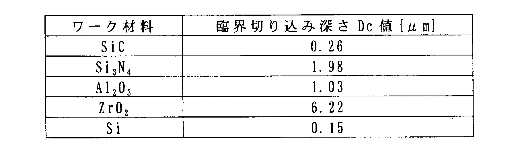
表3から分かるように、例えばワーク材料がシリコンの場合には、その臨界切り込み深さは0.15μmであることから、ブレード26のワークWに対する切り込み深さは0.15μm以下に設定される。仮に切り込み深さが0.15μmを超える場合にはワーク材料へのクラック発生は避けられない。
また、表3に示したワーク材料の中ではシリコンの臨界切り込み深さ(0.15μm)が最も小さく、他の材料と比べて割れやすいことが分かる。このことから、大抵の材料では、0.15μm以下の切り込み深さであれば、原理上クラックを発生することなく材料の変形範囲で加工を進行させることのできる延性モード加工が可能となる。
また、ブレード26のワークWに対する周速度(ブレード周速度)は、ブレード26のワークWに対する相対送り速度(加工送り速度)に比べて十分に大きく設定される。例えば、ブレード26の回転数20,000rpm、ブレード26の外径50.8mmの時、ブレード26の回転速度53.17m/sに対し、ブレード26の相対送り速度は10mm/sに設定される。
なお、ブレード26の切り込み深さや回転速度、ブレード26のワークWに対する相対送り速度の制御は、図1に示したコントローラ24によって行われる。
このような延性モードでのダイシング加工は、切断ラインの溝深さが最終切り込み深さとなるまで、1回あたりの切り込み深さが臨界切り込み深さ以下に設定された状態で繰り返し行われる。
そして、ワークWに対する1つの切断ラインに沿うダイシング加工が終了すると、ブレード26は、次に加工する隣の切断ラインにインデックス送りされて位置決めされ、前記と同様の加工手順により、当該切断ラインに沿うダイシング加工が実施される。
そして、前記ダイシング加工が繰り返されることにより、所定数の切断ラインに沿うダイシング加工が全て終了すると、ワークテーブル30とともにワークWを90度回転させて、前記と同様の加工手順により、前述した切断ラインと直交する方向の切断ラインに沿ってダイシング加工が行われる。
このようにして、全ての切断ラインに沿うダイシング加工が全て完了すると、ワークWは多数のチップに切断分割される。
ここで、本発明の効果を検証するために、上記ダイシング加工方法において、本実施形態のブレード26と従来の電鋳ブレードとを用いてワークに対して溝入れ加工を行った結果について説明する。
[比較実験1](シリコンウェーハ)
本実施形態のブレード26としては、両側テーパタイプ(両Vタイプ)のものを使用した。一方、従来の電鋳ブレードとしては、ブレード厚みが50μm(#600)を使用した。その他の条件については以下のとおりである。
本実施形態のブレード26としては、両側テーパタイプ(両Vタイプ)のものを使用した。一方、従来の電鋳ブレードとしては、ブレード厚みが50μm(#600)を使用した。その他の条件については以下のとおりである。
・装置:ブレードダイシング装置AD20T(東京精密製)
・ブレード回転数:20000rpm
・ワーク送り速度(加工送り速度):10mm/s
・切り込み深さ:30μm
・ワーク:シリコンウェーハ(厚み780μm)
比較実験1の結果を図8A及び8Bに示す。なお、図8A及び8Bは、溝入れ加工後のワーク表面の様子を示したものである。
・ブレード回転数:20000rpm
・ワーク送り速度(加工送り速度):10mm/s
・切り込み深さ:30μm
・ワーク:シリコンウェーハ(厚み780μm)
比較実験1の結果を図8A及び8Bに示す。なお、図8A及び8Bは、溝入れ加工後のワーク表面の様子を示したものである。
図8Aに示すように、本実施形態のブレード26を用いた場合には、ワークに対してクラックが発生させることなく切断溝を形成することができた。
一方、図8Bに示すように、従来の電鋳ブレードを用いた場合には、ワーク表面に微小なクラックが発生した。また、切断溝の底面にもクラックが生じていた。
このように本実施形態のブレード26を用いた場合には、従来の電鋳ブレードを用いた場合に比べて、クラックを発生させることなく、延性モードで安定して精度良い切断加工を行うことができることを確認した。
[比較実験2](サファイアウェーハ)
次に、比較実験1と同様のブレードを用いて、以下の条件で比較実験を行った。
次に、比較実験1と同様のブレードを用いて、以下の条件で比較実験を行った。
・装置:ブレードダイシング装置AD20T(東京精密製)
・ブレード回転数:20000rpm
・ワーク送り速度(加工送り速度):10mm/s
・切り込み深さ:50μm
・ワーク:サファイアウェーハ(厚み200μm)
比較実験2の結果を図9A及び9Bに示す。なお、図9A及び9Bは、溝入れ加工後のワーク表面の様子を示したものであり、図9Aは本実施形態のブレード26を用いた場合、図9Bは従来の電鋳ブレードを用いた場合である。
・ブレード回転数:20000rpm
・ワーク送り速度(加工送り速度):10mm/s
・切り込み深さ:50μm
・ワーク:サファイアウェーハ(厚み200μm)
比較実験2の結果を図9A及び9Bに示す。なお、図9A及び9Bは、溝入れ加工後のワーク表面の様子を示したものであり、図9Aは本実施形態のブレード26を用いた場合、図9Bは従来の電鋳ブレードを用いた場合である。
図9A及び9Bから明らかないように、ワークをサファイアウェーハに変更した場合においても、シリコンウェーハを対象とした比較実験1と同様の結果が得られることを確認した。
[比較実験3](SiCウェーハ)
次に、ストレート形状のブレードを用いて、以下の条件で比較実験を行った。ブレード厚みは、20μm、50μm、70μm厚で行った。
次に、ストレート形状のブレードを用いて、以下の条件で比較実験を行った。ブレード厚みは、20μm、50μm、70μm厚で行った。
・装置:ブレードダイシング装置AD20T(東京精密製)
・ブレード回転数:20000rpm
・ワーク送り速度(加工送り速度):2mm/s
・切り込み深さ:200μm
・ワーク:4H-SiCウェーハ Si面(厚み330μm)
図10Aから10Cは本実施形態のブレード26による溝入れ加工後のワーク表面の様子を示したものであり、図10Aは、ブレード厚みが20μmの場合、図10Bは、ブレード厚みが50μmの場合、図10Cは、ブレード厚みが70μmの場合を示す。
・ブレード回転数:20000rpm
・ワーク送り速度(加工送り速度):2mm/s
・切り込み深さ:200μm
・ワーク:4H-SiCウェーハ Si面(厚み330μm)
図10Aから10Cは本実施形態のブレード26による溝入れ加工後のワーク表面の様子を示したものであり、図10Aは、ブレード厚みが20μmの場合、図10Bは、ブレード厚みが50μmの場合、図10Cは、ブレード厚みが70μmの場合を示す。
ブレード厚みは50μm以下とすることが理想的ではあるが、SiCの場合70μ刃厚では、小さいクラックはあるが、顕著なクラックはなかった。
[比較実験4](超硬合金)
次に、先と同様にストレート形状のブレードを用いて、以下の条件で比較実験を行った。ブレード厚みは、20μm厚で行った。
次に、先と同様にストレート形状のブレードを用いて、以下の条件で比較実験を行った。ブレード厚みは、20μm厚で行った。
・装置:ブレードダイシング装置AD20T(東京精密製、AD20Tは装置の型番)
・ブレード回転数:10000rpm
・ワーク送り速度(加工送り速度):1mm/s
・切り込み深さ:40μm
・ワーク:超硬WC(WC:タングステンカーバイド)
図11A及び11Bは、本実施形態のブレード26による溝入れ加工後のワーク表面(図11A)及び断面(図11B)を示している。同図のように、超硬のような硬質材料でも理想的な延性モード加工を行うことができることを示している。
・ブレード回転数:10000rpm
・ワーク送り速度(加工送り速度):1mm/s
・切り込み深さ:40μm
・ワーク:超硬WC(WC:タングステンカーバイド)
図11A及び11Bは、本実施形態のブレード26による溝入れ加工後のワーク表面(図11A)及び断面(図11B)を示している。同図のように、超硬のような硬質材料でも理想的な延性モード加工を行うことができることを示している。
[比較実験5](ポリカーボネード)
次に、先と同様にストレート形状のブレードを用いて、以下の条件で比較実験を行った。ブレード厚みは、50μm厚で行った。
次に、先と同様にストレート形状のブレードを用いて、以下の条件で比較実験を行った。ブレード厚みは、50μm厚で行った。
・装置:ブレードダイシング装置AD20T(東京精密製)
・ブレード回転数:20000rpm
・ワーク送り速度(加工送り速度):1mm/s
・切り込み深さ:500μm(フルカット)
・ワーク:ポリカーボネード
図12A及び12Bは、それぞれ、本実施形態のブレード26による溝入れ加工後のワーク表面、及びワーク断面を示している。図12Aに示すように、ワーク表面から見るとシャープな切断ラインが観察される。図12Bに示すように、従来の電鋳ブレードと比較しても鏡面の切断面を得たことが分かる。
・ブレード回転数:20000rpm
・ワーク送り速度(加工送り速度):1mm/s
・切り込み深さ:500μm(フルカット)
・ワーク:ポリカーボネード
図12A及び12Bは、それぞれ、本実施形態のブレード26による溝入れ加工後のワーク表面、及びワーク断面を示している。図12Aに示すように、ワーク表面から見るとシャープな切断ラインが観察される。図12Bに示すように、従来の電鋳ブレードと比較しても鏡面の切断面を得たことが分かる。
[比較実験6](CFRP:carbon-fiber-reinforced plastic)
次に、先と同様にストレート形状のブレードを用いて、以下の条件で比較実験を行った。ブレード厚みは、50μm厚で行った。
次に、先と同様にストレート形状のブレードを用いて、以下の条件で比較実験を行った。ブレード厚みは、50μm厚で行った。
・装置:ブレードダイシング装置AD20T(東京精密製)
・ブレード回転数:20000rpm
・ワーク送り速度(加工送り速度):1mm/s
・切り込み深さ:500μm(フルカット)
・ワーク:CFRP
比較実験6の結果を図13A及び13Bに示す。なお、図13A及び13Bは、溝入れ加工後のワーク断面の様子を示したものであり、図13Aは本実施形態のブレード26を用いた場合、図13Bは従来の電鋳ブレードを用いた場合である。
・ブレード回転数:20000rpm
・ワーク送り速度(加工送り速度):1mm/s
・切り込み深さ:500μm(フルカット)
・ワーク:CFRP
比較実験6の結果を図13A及び13Bに示す。なお、図13A及び13Bは、溝入れ加工後のワーク断面の様子を示したものであり、図13Aは本実施形態のブレード26を用いた場合、図13Bは従来の電鋳ブレードを用いた場合である。
従来の電鋳ブレードと比較すると、電鋳ブレードは一つ一つの繊維を引きちぎるため、繊維のきれいな断面を観察できないが、本発明に係るブレードでは一つ一つの繊維が絡まって引きちぎれることなくシャープな繊維端面持つ切断面を得ることができる。
この結果は、本発明に係るブレードの場合、連続した切れ刃が形成され、それぞれの凹み部分が切れ刃になると共にダイヤモンド同士が結合している。そのため、電鋳ブレードでは切れ刃が繊維一本を切断するのに軟らかい結合材で衝撃を吸収してしまい、鋭利に切れ刃が作用しないが、本発明に係るブレードは、ダイヤモンドのせん断応力によって、瞬時の衝撃を吸収することなく鋭利に刃先が作用するためである。
次に、ブレード26のワークWに対する切り込み深さを臨界切り込み深さ(Dc値)以下として延性加工モードでの切断加工が行われる場合であっても実用的なダイシング加工が可能である理由について説明する。
例えば、外径50mmのブレード26を用いてシリコンウェーハからなるワークWを切断加工する場合を考える。なお、ブレード外周端部には結晶粒界に沿った切れ刃(微小切刃)が約10μmピッチで周方向に沿って設けられているものとする。この場合、ブレードの外周長は157mm(157000μm)であることから、約15700個の切れ刃が外周部に形成されていることになる。
まず、1つの切れ刃がワークWにクラックを与えない程度の切り込みとして、0.15μmの切り込みを入れたものとし、その切り込みにより一度の除去量が0.02μm(20nm)であるとする。なお、通常、SiCやSi、サファイア、SiO2などクラックが発生しない臨界切り込み深さはサブミクロンオーダ(例えば約0.15μm)である。そうすると、ブレード外周端部には15700個の切れ刃が存在するため、ブレード一回転あたり原理的には0.314mm(314μm)ほど、加工を進めることができる。ダイシングのスピンドルとして10,000rpmとすると、1秒当たり166回転する。よって、1秒当たりのブレード外周端部での切断除去排除距離は52.124mmとなる。例えば、ブレードの送り速度を20mm/sとした場合、ワーク材料内を押しながら進む速度よりも、ワーク材料をせん断方向に加工して除去する速度の方が速い。すなわち、ワーク材料を切断する上では、ワーク材料の破壊が起きない程度に微小切り込みを入れて、ワーク材料をブレードの進行方向とは直交する水平方向に加工して払いのけ、その払いのけ除去された部分を、ブレードが進行していく形態となる。そのため、クラックが発生する程度の0.1μm以上の切り込みが入る余地がないため脆性破壊を起こすことなく、塑性変形に基づく延性加工領域での切断加工が可能となる。すなわち、高速にブレードを回転させながらブレード回転によるブレード外周端部(先端部)の加工対象材料に対する周速度を、ブレードの加工対象材料に対する送り速度に比べて大きくとることで、延性加工を行うことが可能となる。
なお、実際的には、多少のブレードの偏芯も考慮し少し余裕を持たせて実施し、φ50.8mmのブレード径では、20,000rpmで回転させながら、10mm/s程度の送り速度で加工すれば、材料のクラックは発生しない。
次に、本実施形態のブレード26を用いて延性モードでの加工を実現するために各種検討した結果について説明する。
[ブレードの切刃部の断面形状について]
本実施形態において、ブレード26の外周部に設けられる切刃部40の断面形状は、図4Aから4Cに示した断面形状のうち、図4Bに示した両側テーパタイプ(両Vタイプ)のものが好ましく用いられる。
本実施形態において、ブレード26の外周部に設けられる切刃部40の断面形状は、図4Aから4Cに示した断面形状のうち、図4Bに示した両側テーパタイプ(両Vタイプ)のものが好ましく用いられる。
図14は、両側テーパタイプの切刃部40を有するブレード26を用いてダイシング加工が行われるときの様子を模式的に示した説明図である。まず、ブレード26の切刃部40の任意の位置に設けられる先端部40aは、図14中の(A)部から(C)部に示すように、ワークWの表面部から最深部(最下点)まで徐々に移動しながらワークWの研削を行う。その後、図14中の(C)部から(D)部に示すように、切刃部40の先端部40aはワークWの最深部から表面部に向かって徐々に移動する。このとき、研削溝の側面とブレード26の側面との間には隙間Sが形成される。
すなわち、ブレード26の切刃部40がワークWの表面から内側に切り込んでいる領域において、ブレード回転方向上流側ではワークWの研削が行われる切断部60となる一方で、その下流側ではブレード側面(切刃部40の側面)と溝側面との間に隙間Sが形成され、ワークWの研削は行われず、上流側の切断部60で研削された切り屑が溝内に排出される排出部62となる。
一般にバリやチッピングは、ブレードを材料から抜く際、溝側面と擦れて生じる。このため、例えば図15に示すように、両側の側面部がストレート状に平行に加工されたストレートタイプのブレード90が用いられる場合、ブレード先端部(切刃部)がワークW内部に侵入から外側に抜け出すまでブレード側面は絶えず切断溝の側面と接触する。このため、両側テーパタイプのブレード26に比べて、ブレード先端部がワークW内部から抜けるときに切断溝の側面とブレード側面が擦れやすく、その結果、バリやチッピングを引き起こす要因となる(図15中の(D)部、(E)参照)。また、ダイヤモンド砥粒を埋め込んだ電鋳ブレードが用いられる場合、ブレード側面から突き出ている砥粒が溝側面を引きかき、溝側面のバリやチッピングの発生を助長しやすくなる。
これに対して、両側テーパタイプの切刃部40を有するブレード26によれば、上記のようにブレード26がワークWから抜ける際にはブレード側面と溝側面との間に隙間Sが生じているため、バリやチッピングが生じることがない。また、切り屑の排出に伴って、研削時に生じる熱を切り屑とともに排出することができる。これにより、ブレード26の反りを防ぐことが可能となる。
すなわち、ブレード26の切刃部40がワークW内に切込んで最下点に向うまでワークWを切込み、その後、ブレード26がワークWの最下点を通過して、ブレード26がワークWから抜き出る過程でブレード側面と溝側面との間に隙間Sが形成された状態でブレード26がワークWから抜け出るため、チッピングなどの発生を効果的に抑えることが可能となる。
さらに、上記のような切断加工を行うことによって、ブレード側面と溝側面との接触に伴う摩擦によって生じる熱の発生を極力抑えることにも寄与する。その結果、熱の上昇による切断抵抗の増大などを抑えて、切断屑のブレード26への溶着を防止することができる。また、ブレード26をワークWから抜き出す過程で隙間Sを作りつつ、切断屑を溝内に置き去りにしていくことによって、切断屑に熱を持たせ、熱を排出する効果もある。こうした切断屑は後の洗浄で洗い流すことができる。さらに、ブレード26の発熱やワークWの発熱を抑えることが可能となるので、ブレード26やワークWに多量の水を供給しなくても、これらの発熱を防ぐことが可能となり、ドライな環境で加工することが可能となる。
[ダイヤモンド砥粒の粒径と含有量の関係について]
本実施形態において、延性モードで加工するためにはブレード26の周方向における砥粒配列について考慮する必要がある。その理由としては以下のとおりである。
本実施形態において、延性モードで加工するためにはブレード26の周方向における砥粒配列について考慮する必要がある。その理由としては以下のとおりである。
まず、仮に0.15μmの切り込みを入れるためには、その切り込みを入れるための切れ刃(微小切刃)の大きさとしては、1桁程度の大きい砥粒径や切れ刃間隔である方が望ましい。3桁以上大きい切れ刃間隔となる場合、切れ刃間隔のばらつきも考慮すると、微小な切り込みを入れることは難しい。
一般的に、平板状試料に対して、略等間隔に切れ刃が設定されたブレードを平行移動させて加工する際の最大切込み深さを幾何学的に計算する。以下図16を基にすると、ハッチングした部分を一刃あたりの切り屑部分とすれば、ブレード中心Oと切り屑上の一点Aとを結ぶ線によって決まるACなる長さが一刃あたりの最大切込み深さgmaxとなる。
なお、Dはブレード直径、Zはブレード切れ刃数、Nはブレードの毎分回転数、VSはブレードの円周速度(πDN)、VWはワークの送り速度、SZはブレード一刃あたりの送り量、aは切込み深さとする。
そこで、

とおき、切込み深さgmaxはブレード直径Dに比べて十分小さいとすれば、



したがって、

ここで、ブレードの刃数Zの代わりに、切れ刃間隔λを使用して、Z=πD/λとして、上式に代入すると、一刃あたりの最大切込み深さが求まる。

ここで、πDNは明らかにブレード周速度VSに等しい。すなわち、ブレードによる平板加工において、切れ刃間隔λと一刃あたりの最大切り込み深さの関係は次式で与えられる。

但し、gmax:単位切れ刃あたりの切り込み深さ、λ:切れ刃間隔、Vω:ワーク送り速度、Vs:ブレード速度、a:ブレード切り込み深さ、D:ブレード径とする。
これからも、単位切れ刃あたりの切込み深さを一定以下にするためには、切れ刃の間隔が重要になることが分かる。また、ブレードの回転速度も重要になる。
このgmaxの式に示した関係によれば、Vω:40mm/s、Vs:26166mm/s、a:1mm、D:50mm、λ:25μmとしても、0.027μm程度の切り込み量だけとなり、0.1μm以下の切り込み量となる。この範囲であれば、臨界切り込み深さ以下であるから、延性モード加工の範囲である。
延性モード加工を行うためには、必ず上記の条件を満たさなければならない。
さらには、実用的な条件として、2インチ径のブレード(直径50mm)を10000rpmで回転させて加工する条件で、ワーク厚みが0.5mm、ワークの送り速度を10mm/sとし、ブレード外周部分の切れ刃間隔を1mmピッチで形成したとする(Vω:10mm/s、Vs:157×104mm/s、a:0.5mm、D:50mm、λ:1mm)。
その条件であっても、上の式に代入すると、一つの刃が切込む臨界切込み深さは0.08μmとなり、依然0.1μm以下の切込み深さとなる。よって、ブレードが偏芯せず理想的にすべての切れ刃がワークの除去加工に作用するとした場合、臨界的にはブレード外周部に形成できる切れ刃間隔は1mm以下までであれば、致命的なクラックを生じる過剰な切込みを与えることなく、加工を進行させることが可能となる。
なお、SiCでは、クラックを生じさせない臨界切込み深さは0.1μm程度である。他のサファイア、ガラス、シリコンなどにおいては、同クラックを及ぼさない臨界切込み深さは、0.2~0.5μm程度であるため、臨界切込み深さを0.1μm以下と設定しておれば、ほとんどの脆性材料はクラックを及ぼすことなく、材料の塑性変形域内で加工を行うことができる。
よって、ブレード周囲につける切れ刃間隔は1mm以下である方が望ましい。
一方、ブレード周囲の切れ刃間隔は1μm以上である方がよい。仮に、平均的な切れ刃間隔が1μm以下の場合、すなわちサブミクロンオーダの切れ刃間隔を有する場合、臨界切込み深さ量と材料除去の深さ単位がほぼ同程度になってくる。すなわち、両者ともサブミクロンオーダとなるが、このような条件では実際に一つの切れ刃が期待する除去量に達することは難しく、逆に目詰まりモードによって加工速度は急激に低下する。
こうした状況下では、一つの切れ刃の臨界切込み深さは別として一つの切れ刃が除去できる深さ自体に無理があると考えられる。
なお、上記の考えは、ワークを切断する断面積が一定である場合に成り立つ。すなわち、試料は略平板状試料において、ブレードを高速回転させて、ブレードを、平板状ワークに対して一定の切込み深さに設定し、ワークをスライドさせながら切断加工するブレードに関する内容において合致する。
また、上記の式は、一つの切れ刃が与える臨界切込み深さは、切れ刃間隔によることも重要なことである。一つの切れ刃が切り込む量は、次の切れ刃との間隔に影響し、ある部分で切れ刃間隔が大きい部分があると、所望の臨界切込み深さより深く切込みクラックを及ぼす可能性を示している。よって、切れ刃間隔は重要な要素であり、安定した切れ刃間隔を得るために、その切れ刃間隔を材料組成から自然に設定されるように、単結晶ダイヤモンドを焼結したPCD材料が好適に使用されるのである。
但し、ダイヤモンド砥粒の粒径(平均粒子径)が大きくても、その隙間が密に敷き詰められており、実質的な砥粒間隔がその粒径よりも小さいオーダであれば、さらに砥粒の切り込みを抑制し、制御することが可能となる。実際には、理想的な粒径として1μmから5μm程度のダイヤモンド砥粒が望ましい。
なお、粒径が必ずしも切れ刃間隔になるとは限らない。正確にツルーイングされている場合は、切れ刃の間隔は粒径に相当するかもしれないが、通常切り出してドレッシングされた状態では、切れ刃間隔は砥粒径よりも大きくなる。
すなわち、粒界で厳密に規定されれば、一つの砥粒の両脇に存在する隙間が、切れ刃に相当すると解釈されるが、実際はいくつかの砥粒が固まりで抜け落ちて、自然に一定周期の切れ刃を形成するようになる。これは、ブレードを平均的に荒らすことで切れ刃ピッチを形成することができる。
図17A及び17Bには、ブレード外周端を粗さ計で測定した結果を示す。さらに図18A及び18Bには、表面状態の写真を示す。焼結体であるため、基本的には表面に見える部分はすべて砥粒であるダイヤモンドで構成される。
また、表面の凹凸はダイヤモンド粒界から形成されており、自然な略等間隔の凹凸形状が構成される。この一つ一つの凹部が材料に切込むための切れ刃として作用する。この切れ刃ピッチは、図から明らかなように、4mmレンジで260個、263個の山数があるため、約15μmピッチの切れ刃間隔となっていることが分かる。なお、本材料は、住友電工ハードメタル社製のDA200で構成されており、構成されるダイヤモンド粒子の粒径は公称1μmである。このように、粒径は小さくても、切れ刃間隔はそれよりも大きく形成されており、図から分かるように略等間隔に形成されている。
こうした等間隔な切れ刃は、単結晶の微粒子を焼結させて作られたダイヤモンド焼結体によって、ブレードそのものを形成していることによるものである。
このように、ブレード先端部分は、ワークを切り進めるために大きく凹凸をつけるようにしているが、それに対して、ブレード先端部分に比べてブレード側面部分は除去後のワーク切断後の端面を鏡面になるように研削する。そのため、ブレード先端部は切り進めるために粗く成形しており、ブレード側面部はそれに対して細かく成形している。
なお、従来の電鋳ブレードでは、通常ダイヤモンド砥粒の間隔は、その粒径と比べて格段に大きい。これは、まばらに振りまいたダイヤモンド砥粒を単にメッキしているためであり、メッキする時点で全く異なる。
これに対して、本実施形態のブレード26では、ダイヤモンド焼結体は焼結助剤が焼結によりダイヤモンド内に溶融してダイヤモンド同士が強固に結合するため、非常に硬質かつ高強度に構成される。また、ダイヤモンド焼結体は電鋳ブレードと比較して相対的にダイヤモンド含有量が多く(例えば、特開昭61-104045号公報を参照)、電鋳ブレードと比較すると相対的に強度が大きい。
また、ブレード材料内部の多くがダイヤモンドで占められているために、ダイヤモンド体積よりも、それ以外の部分(焼結助剤含む)の方を小さくすることが可能となり、ダイヤモンド焼結体の場合では、仮に粒径が大きくてもダイヤモンド粒径の隙間を実質的にミクロンオーダにすることが可能になる。
また、ダイヤモンド砥粒の間の凹み部分が本発明では極めて重要な役割を果たす。ダイヤモンド砥粒は非常に硬質であるが、焼結助剤として入れたコバルトは一部はダイヤモンド内に浸透するが、一部はダイヤモンド砥粒間に残っている。この部分はダイヤモンドと比べると硬度的に少し柔らかいので、切断加工において摩耗しやすく少し凹む形になる。すなわち、ダイヤモンド同士に挟まれた部分があって、その間の凹みを微小な切れ刃にすることで、過剰な切り込みを与えることなく、安定した切り込みを得ようとしているものである。また、微小な切れ刃は、ダイヤモンド同士に挟まれた凹みのみならず、ダイヤモンド粒子自体が欠落してできた凹み部分も切れ刃として作用させることもある。この切れ刃間隔は、先の式に示した一つの刃あたりの臨界切込み深さを超えない程度の間隔に設定しておけばよい。
例えば、25μm粒径のダイヤモンド砥粒を焼結で固める場合を考える。ここでは分かりやすくするために、ダイヤモンド砥粒は25μm四方の立方体であるものと仮定する。ダイヤモンド砥粒同士を結合するために、25μmの外側で両側1μmの部分を別の粒子と結合するための結合部分として利用するものとする。すると、27μm四方の立方体となる。その場合に、ダイヤモンド砥粒部分が締める体積%は78.6%程度になる。よって、80%以上程度のダイヤモンド含有量があれば、たとえ、25μm粒径のダイヤモンド砥粒であっても、そのダイヤモンド砥粒間の隙間、すなわち粒子間隔は実質せいぜい1~2μm程度となり、その凹み部分が切り込みを与えるための切れ刃(微小切刃)となる。また、2μm程度の粒子間隔であれば、その粒子間隔においてそのピッチの粒子がワーク材料に押し込まれたとしても、そのワーク材料の変位はダイヤモンド砥粒の間隔と比べて1桁以上小さくなる。すなわち、0.15μmかそれ以下となる。また、25μmピッチで切れ刃(微小切刃)が形成されているとして、50mmのブレード径の場合、全周約157mmあたり6280個の切れ刃が形成されている。仮にブレードを20000rpmで回転させるとして、1秒当たりに切れ刃は、2093333個作用させることができる。
この1つの切れ刃が0.15μm以下の切り込みを入れて、仮にその1/5である0.03μmほど、1秒あたりに除去するとする。そうすれば、2093333個の微小切刃であれば1秒当たり、62799μmほど除去可能となり、理論上、一秒当たり6cm程度切り進めることが可能となる。
こうした点からも、理論上、25μm粒径のダイヤモンド砥粒であっても、80%以上のダイヤモンド含有量を有しておれば、ダイヤモンド砥粒同士が結合している隙間の部分は1~2μm程度となり、その結果、過剰な切り込み量を与えることなく、安定した切り込み量として0.15μmとすることが可能となる。
また、ダイヤモンド砥粒の粒径が25μmではなく、それ以下であっても、ダイヤモンド含有量を80%以上とすれば切り込みや材料除去量の点において、臨界切り込み深さを越えることがないため問題はなく、クラックを発生することなく延性モードでの加工を行うことが可能となる。
以上のように、ダイヤモンド焼結体の場合、ダイヤモンド砥粒(ダイヤモンド粒子)間が密に詰まっているため、ダイヤモンド含有量が非常に高く、個々のダイヤモンド砥粒がそのダイヤモンド砥粒のサイズの切れ刃として作用する。
また、ダイヤモンド砥粒の粒径と比較して、ダイヤモンド砥粒間の距離が格段に小さくなり、切り込み量として正確に制御することが可能となる。その結果、切り込み深さが所定の当初目論んだ切り込み深さ以上に大きくなることはなく、加工中絶えず安定した切り込み深さを保証する。その結果、ミス無く、延性モードの切断加工を行うことが可能となる。
なお、25μm程度の大きい粒径では、ダイヤモンド砥粒の含有率をさらに多くすることができ、通常市販されているものであれば93%程度の含有率(ダイヤモンド含有量)のものがある。そうであれば、なおさら、焼結助剤の割合が減少し、すなわち、ダイヤモンド砥粒同士の隙間は、実際微小になる。
ただし、25μm以上の大きい粒径のダイヤモンドを使用する場合、先に述べたように切れ刃間隔としては、延性モード加工を行う上で十分なのであるが、一方でブレードの刃厚を50μm以下とする場合には、そうした大きい砥粒では製作することはできない。
なぜならば、例えば、40μmの刃厚で製作する場合は、少なくともブレード断面に二つ以上のダイヤモンド砥粒を要していないとならないが、理論上二つ入らず、1.6個となるからである。
[ワーク材料の変形を考慮したブレードの刃厚について]
延性モードの加工を安定して行うためには、前述したように、深さ方向においては切り込みを0.15μm程度以下にする必要がある。この切り込みを安定的に行うためには、切り込み幅から考慮されるワーク材料の厚み方向変位(縦方向変位)も考慮しなくてはならない。
延性モードの加工を安定して行うためには、前述したように、深さ方向においては切り込みを0.15μm程度以下にする必要がある。この切り込みを安定的に行うためには、切り込み幅から考慮されるワーク材料の厚み方向変位(縦方向変位)も考慮しなくてはならない。
すなわち、広い範囲でブレード面(ブレード26の回転軸に垂直な面)に平行な方向に切り込みを入れて除去する場合、それに伴うワーク材料の変形は縦方向(切り込み深さ方向)にも広がる。すなわち、ワーク材料のポアソン比を考慮して、ある程度有限の切り込み幅とする必要がある。なぜなら、極端に切り込み幅を大きくすると、ポアソン比の影響による材料変形で縦方向にもその変形余波が及んでしまう。これにより、所定の設定した臨界切り込み深さ以上の切り込み量が入ってしまい、結果的にワークWの割れを誘起することがあるためである。
ここで、ポアソン比の影響を考慮した場合に安定的に切り込みを与えることができるブレードの刃厚(ブレード幅)について検討する。表4は、脆性材料のヤング率とポアソン比との関係を示したものである。
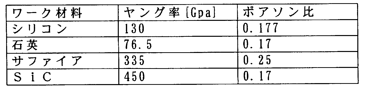
ここでは、1つの切れ刃がワーク材料に切り込むものとする。また、細いストレートなブレード先端は、特段恣意的に鋭利化するものではなく常に加工すると、断面形状は略半円形になるものとする。
そうした場合、例えば0.15μmの切り込みを直方体状のもので与えるとすれば、略1μm程度の幅で平行に切り込みを与えると、ポアソン比によれば、付随的に縦方向に単純に0.17μm程度変位することになり、これは実際の切り込み量近くになる。実際は、ポアソン比の影響は縦変位のみならず、水平方向にも及ぶため、概算で1μm程度の幅であれば切り込み量として与えることができる。
しかし、図19に示すように、略半円状のブレード先端(ブレード外周端部)をワーク材料に対して0.15μm切り込む場合は、その幅として平行に一様に変位させているわけではないので、外周の立ち上がりを考慮すると、約5μmの円弧状の幅であればポアソン比の影響を受けずに切り込むことが可能となる。すなわち、Rsinθ=2.5となり、R(1-cosθ)=0.15となる。
これを逆算すると、先端部分のブレード半径は約25μm程度となり、上記5μm幅の切り込みを与える頂角は12度程度になる。
よって、材料に切り込むブレードの幅としては、約50μm以内には抑えておく必要がある。それ以上となると、各点平面的に同時に材料に作用することになり、時として微小なクラックを誘発することにつながる。
なお、それ以上の曲率、すなわち、30μm程度のブレード厚みであれば、基本的に上記の状態よりも局所的に切れ刃が作用するため、基本的に切れ刃の横幅が切り込み深さに影響を及ぼすことはなく安定的に切り込むことができる。
なお、ブレードの幅については、延性モードの加工を行う上での観点もあるが、ブレード単体の座屈強度とも大きく関係する。
上記ブレードの幅は、ワーク厚みからも制限を受ける。
ここで、ブレードの幅とワーク厚みの関係を示す。
ワークは、一般的にはダイシングテープに支えられている。ダイシングテープは弾性体であるため、ワークのような硬い材料とは異なり、少しの応力で多少なりとも縦方向(Z方向)に変位しやすい。ここで、ワークをブレードで切断する際には、ワーク内の切断される部分の断面形状、図20Aに示される斜線部分が重要になる。
ブレード厚み(ブレード接触領域)lがワーク厚みhよりも大きいl>hの場合、図20Bに示すようにブレードが接する部分(加工除去される部分)は横長の長方形になる。こうした除去対象の断面部分が横長の長方形になる場合においては、上部から分布荷重が作用すると、撓みによって弓なりに曲がる状態が発生し、その撓みの最大変位は以下となる。(実際は板の撓みではあるが、単純に梁の問題と考え分布荷重が作用と仮定)

断面が奥行きbで高さhの長方形梁の場合、

であるため、上式は以下となる。

最大撓みは、梁の中央部分で、ワーク厚みhの3乗に反比例し、ブレード接触領域lの4乗に比例する。
特に、(l/h)3において、l/hが1を境にして、l/hが1より小さくなれば撓みは格段に小さくなり、逆にl/hが1より大きくなれば撓みは格段に大きくなる。これより、ブレード厚み(ブレード接触領域)lとワーク厚みhの相対的な厚みの形状で撓みが発生する場合と、発生しない場合が分かれる。
このブレード接触領域がワーク厚みよりも大きい場合(l>h)、ワークは接触領域内で撓みが発生するが、ワークが撓む場合、断続的に面内で上下に撓みによるワークの振れの振動が発生し、所定の切込みを達成できなくなる。結果的にワークの縦方向の振動でブレードから致命的な切込みが与えられ、ワーク表面に割れが発生する。
よって、特に本発明のPCDブレードによる加工では、クラックフリーの加工を行うため、所定の切込み深さを安定して忠実に守る必要がある。そのためには、切れ刃間隔制御による切込み深さを設定する他にも、ワークそのものの加工時おける縦振動を抑えることで、所定の切込みを精度よく確保しなればならない。
そのためにも、ブレード厚みは、図20Cに示すように対象ワークの厚みよりも薄くしなければならない。
例えば、ワーク厚みが50μm以下の場合は、ブレードの幅は当然50μm以下にする必要がある。
この場合には、ワークは接触領域内で撓むことはない。一方、接触領域内で屈曲ないしは圧縮させる応力が働くが、ワークは横方向には密な連続体でポアソン比により変形が拘束される。そのため、局所的にはワークから反力としてブレードから与えられた応力に作用し、結果的に、割れを発生することなく所定切込みでの加工が可能となる。
[従来のブレードとの比較]
特許文献1にあるような電鋳ブレードの場合、ダイヤモンドを分散させ、その上からメッキを行うため、ダイヤモンドはまばらに存在し、しかもそれらは突き出した構成となる。その結果、突き出した部分は、当然のように過剰な切り込みを与えてしまうこともあり、脆性破壊を誘発する。なお、溝の底部や側面部も連続している部分は、ワーク材料も互いに密に構成されているため、すぐさまクラックは入りにくいが、ブレードが抜ける部分が最もクラックや割れが入りやすい。それは、ブレードが抜ける際に、バリがでることと同じであり、ワーク材料は連続ではなく支えがないからである。
特許文献1にあるような電鋳ブレードの場合、ダイヤモンドを分散させ、その上からメッキを行うため、ダイヤモンドはまばらに存在し、しかもそれらは突き出した構成となる。その結果、突き出した部分は、当然のように過剰な切り込みを与えてしまうこともあり、脆性破壊を誘発する。なお、溝の底部や側面部も連続している部分は、ワーク材料も互いに密に構成されているため、すぐさまクラックは入りにくいが、ブレードが抜ける部分が最もクラックや割れが入りやすい。それは、ブレードが抜ける際に、バリがでることと同じであり、ワーク材料は連続ではなく支えがないからである。
また、特許文献2のブレードの場合は、CVD法で成膜されているために、突出したクラックはない。ただし、ブレード端部の切れ刃の配列、ブレード側面部の平面状態やうねりなど、制御することは不可能である。
特に、ブレード側面部に限れば、成膜時の膜厚むらはそのままブレードの厚みむらに相当する。また、成膜の表面そのものは無垢な面であるため、材料側面と完全に接触して摩擦熱を誘発することや、微妙なうねりがあり、そのうねりで材料を叩き割ることもある。
それに対して、本実施形態のブレード26では、軟質金属の焼結助剤を用いて焼結されたダイヤモンド焼結体で一体的に構成されるため、ブレード外周端部とブレード側面部を摩耗処理で成形することが可能となる。特にブレード外周端部は切れ刃となるため、前述のように、所定の切れ刃とするためにさらに摩耗処理条件を変更することも可能である。
一方、ブレード側面部の役割としては、切り屑を排除することがまず第一にあるが、ワーク側面との接触を加味すると、ある程度の接触しつつも、過度に接触せず、安定してワーク側面を微小に削る程度に荒らされていることが望ましい。
このようにブレードの外周端部と、ブレード側面部をそれぞれその状態に応じて所望の表面状態を設計し、そのような表面に製作できることについていずれの引用文献の技術も不可能である。
なお、スクライビングで使用されるブレードの場合、以下のような理由から延性モードでの加工には適さない。
すなわち、スクライビングでは、ブレード自体を回転させるわけではないので、等間隔に揃った微小な切れ刃自体が必要になるものではない。また、たとえ、切れ刃があったとしても、ミクロンオーダの結晶粒界に沿った微小切刃でなく、大きい切れ刃とする場合、高速回転のダイシングでは材料にクラックを与えてしまい到底使用することはできない。
また、結晶粒界に沿った微小な切れ刃をもつブレードをスクライビングで使用しても、その微小な切れ刃はスクライビングのクラックを与える切れ刃として機能するものではない。
また、スクライビングは、ブレードを鉛直方向に押圧する。そのため、ブレード内を通す軸に垂直下方向に応力を与え、ブレードを軸に対して滑るように構成する。軸とブレードを固定して使用するものではないため、軸に対するブレードのクリアランスは低く、また、ブレード自体が高速回転しないので、ブレードの片側面に基準面を設ける必要もない。
また、50μm以下、とりわけ30μm以下の細い刃先のスクライビング用のブレードを製作しても、ブレードは薄い軸受けで受け、またブレードの片側面に広い面で受ける基準面が存在しないため、ワークに対する精度良い真直度を確保できない。その結果、細い刃先のブレードは座屈変形してしまうことになり使用できない。
[ブレードの強度について]
次に、ブレード材料の強度(弾性率)とワーク材料の強度(弾性率)の関係について述べる。
次に、ブレード材料の強度(弾性率)とワーク材料の強度(弾性率)の関係について述べる。
ブレードがワークに一定量切り込んでそのまま切り進めるためには、ブレード材料はワーク材料に対して大きい強度が必要となる。仮に、単純にブレード材料がワーク材料に対して軟らかい材料、すなわちヤング率の小さい材料で構成されていた場合、極細いブレード先端部分をワーク表面に作用させ、ブレードを進めようとしても、ワーク材料が高弾性率の部材であればワーク表面を微小に変形させることができず、それを無理に変形させようとすると、ブレード自体が座屈変形する。そのため、結果的に加工が進行しない。ここで、両端支持の長柱の座屈荷重Pは次式で与えられる。

なお、E:ヤング率、I:断面二次モーメント、l:長柱の長さ(ブレード径に対応)とする。
仮に、ワーク材料より低い弾性率を有するブレードの場合、ブレードの座屈変形を抑えながら加工を進展させるのであれば、座屈変形しない程度の断面二次モーメントが必要となり、具体的にはブレード厚みを分厚くせざるを得ない。しかし、特に脆性材料を加工する場合でブレード厚みがワーク厚みより厚い場合、ワーク材料表面を変形させ押し割ってしまう。よって、ブレード厚みはワーク厚みよりも薄くしなくてはならない。
そうすれば、結果的には、ブレード材料はワーク材料よりも高弾性率のものを使用しなくてはならないことになる。
こうした関係は、従来の電鋳ブレードと本実施形態のブレード26との差に相当する。すなわち、電鋳ブレードは、ニッケル等の結合材で結合しており素材的にはニッケルベースとなる。ニッケルのヤング率は219GPaであるが、例えばSiCは450GPaである。ニッケルに電着されているダイヤモンド砥粒自体は970GPaであるが、それらは個別に独立に存在するため、結果的にニッケルのヤング率に支配される。そうすれば、原理上、ワーク材料が高弾性であるため、付随的にブレード厚みを増して対応しなくてはならない。その結果、電鋳ブレードの厚みを太くして接触面積を大きくすることを余儀なくされ、クラックや割れを誘発することになる。
これに対して、本実施形態のブレード26の場合、ダイヤモンド焼結体のヤング率はダイヤモンド同士が結合しているため、700~800GPa相当である。これは、ほとんどダイヤモンドのヤング率に匹敵する。
ここで、ブレード26の弾性率がワークWの弾性率に比べて大きい場合、ブレード26は切り込みを与えた際に、ブレード26ではなくワークW側の表面が変形することになる。ワークW側が変形したまま、そのまま切り込みを入れて加工除去していくことが可能となる。しかも、その過程でブレード26が座屈変形することはない。よって、非常に鋭利なブレード26であっても、座屈することなく加工を進めることが可能となる。
表5に各材料のヤング率を示す。表4から明らかなように、ダイヤモンド焼結体(PCD)は、サファイアやSiCなどの大抵の材料と比較しても格段にヤング率が高い。このため、ワーク材料厚みより細いブレードであっても加工することが可能となる。

次に、ワーク材料とブレード材料の硬度の関係を述べるが、高度の関係も先の弾性率と同様である。
ブレード材料の硬度がワーク材料の硬度に比べて低い場合、例えば電鋳ブレードの場合は、ダイヤモンドを軟質の銅やニッケルが支えている。表面のダイヤモンド砥粒は非常に硬度が高いが、その下でダイヤモンド砥粒を支えているニッケルの硬度は、ダイヤモンドと比較すると極めて低い。よって、ダイヤモンド砥粒に衝撃が与えられると、その下のニッケルが衝撃を吸収することになる。結果的に、電鋳ブレードの場合はニッケルの硬度が支配的になるため、結果、硬質のダイヤモンド砥粒がワーク材料に衝突し、ワークに切り込みを与えようとしても、結合材がその衝撃を吸収するため、結果的に所定の切り込みを与えることが難しい。よって、加工を進行させるためには、ある一定以上のブレード回転数をダイヤモンドに衝撃的に与えないことには加工が進まない。また、この際にニッケルに一瞬衝撃が吸収され、その反力がダイヤモンド砥粒にのって大きな力でワーク材料を押圧するため、ワーク材料を脆性破壊させてしまう。
それに対して、本実施形態のブレード26の場合、ダイヤモンド焼結体はダイヤモンド単結晶に匹敵する硬度を有し、サファイア、SiCなどの硬脆性材料と比較しても格段に高い硬度である。その結果、ダイヤモンド焼結体の表面に形成される凹部からなる切れ刃(微小切刃)がワーク材料に作用しても、その衝撃はそのまま微小な切れ刃部分に局所的に作用し、鋭利な先端部分と相まって、極微小部分を精度よく除去加工することが可能となる。
[ブレードの切れ刃付けについて]
次に、ブレードの切れ刃付けについて説明する。
次に、ブレードの切れ刃付けについて説明する。
上述した実施形態では、レーザ光(パルスレーザ)を用いてブレード外周端部に切れ刃付けを行う方法として、ブレード面(ブレード26の回転軸に垂直な面)の法線方向(ブレード法線方向)からレーザ光を照射することにより切れ刃を形成している。
しかしながら、本発明者らが鋭意検討したところ、上記のような切れ刃付けの方法では、レーザ光が照射されていない逃げ面で磨耗が進行し、切れ刃は比較的早期に摩滅してしまうことが判明した。
そこで、さらに検討を重ねた結果、レーザ光をブレード法線方向ではなく、ブレード面に平行な方向(ブレード接線方向)から照射することにより、ブレード外周端部には、掬い面と逃げ面を有する切れ刃が周方向に沿って連続して形成され、安定した加工を実現することできるようになった。以下、本発明のより好ましい態様について説明する。
まず、先の説明と一部重複するが、本発明に係るブレード(PCDブレード)の切れ刃付けの考え方と従来の砥石との違いについて説明する。
図27A及び27Bは、従来の砥石と本発明に係るブレードによる砥石切れ刃に関する違いを示す模式図である。従来の一般砥石は、図27Aに示すように、砥粒と結合材で構成される。目詰まりや砥粒の摩滅を防ぐには、結合材を削りながら自生発刃させることで切れ味を確保する。それに対し、本発明に係るブレード(PCDブレード)は、図27Bに示すように、80%以上(例えば、約90%)のダイヤモンド砥粒と極微量の焼結助剤で一体的に焼結した一様なPCD素材で構成される。PCDは、一般的に切削工具として使用されてきたが、本発明では、一様なPCD表面にパルスレーザで恣意的に刻みをつけ、切れ刃を等間隔に恣意的に形成することで、延性モード加工を行う砥石として機能させる。切れ刃は、砥粒径とは関係なく独立して設定できることから、切れ刃サイズが砥粒径と同じになる従来の砥粒番手の概念とは全く異なる。
仮に、PCDブレードではなく、結合材で砥粒を保持して形成された従来の砥石(例えば、ニッケル等の電鋳ブレード、ビトリファイド、レジンブレード)にレーザ加工を施した場合、結合材とともに砥粒(ダイヤモンド砥粒)も同時に吹き飛ばされる。このときの様子を図28に示す。ダイヤモンド砥粒は600℃でグラファイト化する一方、例えば結合材のニッケルの融点は1455℃であり、酸化したニッケルの融点は1900℃である。そのとき、ダイヤモンド砥粒はグラファイト化するが、ニッケルは酸化して残り、内部の硬質なダイヤモンド砥粒を覆う場合がある。そのまま砥石として加工すると、表面にダイヤモンド砥粒がなく、酸化ニッケルが支配的となるため、レーザ光を照射した部分がそのままダイヤモンド砥粒のエッジとして機能しない。
すなわち、レーザの当て方などで、掬い面や逃げ面を形成できるものではない。基本的に結合材を除去して下地の新しい砥粒を発生する原理にとどまり、レーザ照射そのものが切れ刃を形成するといった原理に属するものではない。
こうして形成した表面は、基本的にレーザ光によって、切れ刃間隔を形成されたものではない。なぜなら、ある周期でレーザ光を照射したとしても、その照射されたピッチで形成された凹凸の凸部は、ダイヤモンド砥粒が存在せず、切れ刃としての機能を果たさないからである。単純に、結合材を削り取って下地の新しいダイヤモンド砥粒を出しやすくしているだけである。
結局、切れ刃間隔は、下地のダイヤモンドの砥粒や集中度に依存した形となり、レーザ光のパルス周期と関係ない。すなわち、レーザ光のパルス間隔などによるレーザ痕の間隔が、切れ刃の間隔にならない。これは、本発明に係るブレード(PCDブレード)をレーザ光の照射によるドレッシングを行って切れ刃を形成することとは全く異なる原理で、単に表面の結合材をレーザ光の照射によるジュール熱で溶かしているに過ぎず、レーザ光のパルス間隔で形成した凹凸を切れ刃として利用するものではない。
一方、本発明に係るブレード(PCDブレード)は、ほとんどがダイヤモンド砥粒で構成されているために、レーザによって局所的に熱せられて昇華する。このときの様子を図29に示す。同図に示すように、レーザ光が照射されると、ブレードを構成するダイヤモンド砥粒の一部がグラファイト化して残るが、これは物理的にもろく、加工中で容易に剥がれ落ち、その下にあるダイヤモンド砥粒が作用する。レーザ光(レーザビーム)の照射角度、強度や集光手段にもよるが、ブレード外周端部(砥石表面)に、ブレードのワークに対する進行方向に略垂直な稜線をもった尖った形状が形成され、その稜線部分はほとんどがダイヤモンド砥粒で形成される。その結果、ブレードの進行方向に対して稜線を境として掬い面と逃げ面が形成され、これが切れ刃に相当する。
ブレードを回転させながら切れ刃加工する場合、レーザ光のパルス周期やブレードの回転数を変えることで、切れ刃間隔を調整することができる。従来の砥石の場合、通常番手(砥粒径)や集中度で、一つの切れ刃の切込み量や切れ刃間隔を変化させる。しかし、本発明のように、ダイヤモンド焼結体をレーザ光で切れ刃付けする方法では、こうした番手や集中度に相当するパラメータをレーザ光のパルス周波数や出力、パルス幅で調整することによって任意の形態の切れ刃サイズを構成できる。これは、各ワークの切込みをワーク毎に一つの素材(PCDブレード)で自由に設定できることを意味する。なお、ダイヤモンド焼結体の場合では、ダイヤモンド砥粒(ダイヤモンド粒子)を大きくすると、硬度は増すが靱性は低下する。靱性を増すためには、ダイヤモンド砥粒を微粒化して焼結助剤の含有量を少し多くするとよい。通常、80%以上のダイヤモンド含有量は必要だが、ダイヤモンド焼結体の硬度を保ちつつ靱性を確保しながら、レーザ光で切れ刃付けした際に切れ刃の先端のダイヤモンド硬度を確保する場合は、70vol%以上、可能ならば70vol%を超えたダイヤモンド砥粒で構成することが必要となる。
なお、70vol%より多いダイヤモンド砥粒を焼結して構成されている製品には、トーメイダイヤ社製TDC-HM80,TDC-GM80などがありこれらの素材も好適に使用できる。
また、通常、研削において電鋳などの場合の砥粒分布は平均的に切れ刃を設定することはできても、ローカルな箇所では砥粒分布の濃淡などにより調整することはできない。しかし、レーザ光(パルスレーザ)による切れ刃形成は、先に述べたように延性モード加工を実現するための必須条件になる。ローカルな場所でも理論通りにブレードの外周端部に周方向に沿って等間隔の切れ刃を形成することは、一つの切れ刃の切込み量を厳密に制御することにつながり、理想的な延性モード加工を実現し、鏡面加工を行うことが可能となる。
ところで、上述した実施形態では、ブレード外周端部への切れ刃付けを行う方法として、図30に示すように、レーザ光を用いて、ブレード法線方向からレーザ光を照射することにより切れ刃を形成している。図31に、レーザ光(パルスレーザ)による切れ刃付けと逃げ面磨耗の状態を示す。同図から分かるように、ブレード法線方向からレーザ光を照射することにより切れ刃を形成する方法では、長期間にわたって安定して使用する場合には、次のような問題があることが明らかになった。
まず、1つ目の問題としては、レーザ光の入側と出側で穴径が変わることである。図31に示すように、入側の方がどうしても穴径が広くなり、出側で穴径が小さくなる傾向がある。この場合、加工ではレーザ光の入側と出側で切削抵抗が異なることに対応し、ワークWの割れにつながりやすい。
また、2つ目の問題は、切れ刃が早く磨耗していくことである。これは、切れ刃を形成した際に、その切れ刃と切れ刃の間は、フラットのままになる(図23参照)。そのときにワークとこすれて摩滅しやすくなってしまう。特に切れ刃部分の切り屑がそのまま巻き込まれながら、フラットの部分に入り込み、さらに先端部の摩滅が早まることになる。図31にも示すように、使用前(図31の左側の写真)と使用後(図31の右側の写真)で穴がない先端部分の摩滅が早まることになる。また、使用前と使用後で穴がない先端部分の摩滅が早急に進行し、摩滅で光っていることが分かる。これは、逃げ面磨耗に相当し、逃げ面が存在しないために、その逃げの部分が摩滅することになる。
同じレーザで加工するにも、切れ刃を形成する上で逃げ面を形成することは非常に重要となる。本発明のより好ましい態様では、図32に示すように、ブレード面に平行な方向(ブレード接線方向)からレーザ光を入射し、すなわち加工対象のブレードの進行方向に沿ってレーザ光を入射し、掬い面と逃げ面を有する切れ刃をブレード外周端部の周方向に沿って連続的に形成する。ビーム状のレーザ光(レーザビーム)による加工の場合、図33に示すように、ブレード接線方向にレーザ光を入れることでレーザ光が照射された部分は掬い面となり、途中のレーザ光が通過した部分は逃げ面になる。このようにして、ブレード面内に掬い面と逃げ面が形成され、その間に稜線が生じて切れ刃に相当する形になる。
こうして形成された、ブレード外周端部に一定の間隔の稜線が形成され、その稜線を境に掬い面と逃げ面を形成すること自体は、ブレード面の横から、すなわち、ブレード面の法線方向からレーザを照射して形成した方法とは、作用効果が全く異なる。所定の切込みを安定して入れるには、逃げ面が形成されていることが非常に重要になっている。
また、掬い面と逃げ面を形成する際にも、レーザ光のようにビームで形成することに非常に意義がある。ビームで形成する場合、ブレード面の法線方向からレーザ光を照射することにより切れ刃を形成すると(図30参照)、ビーム特性上、ビームが入射する手前は大きく穴が開くが、出口側は、穴径は小さくなり、結果的にブレードの通過・進行方向に対してきれいに垂直な切れ刃ができない。
それに対し、レーザ光のビームをブレードの運動する方向に迎え撃つ形で平行かつ低角度で照射した場合、掬い面と逃げ面をきれいに形成できる。また、ビームの入射先端が掬い面の形成に寄与し、ビームの側面部が逃げ面を形成することに寄与する。掬い角は小さい負の角であることが望ましいので、ブレード面に対して仰角を低い角度で入射させることと切り立った掬い面ができる。すなわち、ビームの直進性という特性を利用することで、掬い面と逃げ面を形成することが可能となるのである。
以上のように、ブレード法線方向ではなく、ブレード接線方向からレーザ光を照射することにより切れ刃付けを行う態様によれば、ブレード外周端部に掬い面と逃げ面を有する切れ刃を周方向に沿って連続的に形成することができる。
以下、図32に示した構成を用いて、PCDブレードに切れ刃付けを行ったときの実施例について説明する。なお、ブレードは、図32において右回転で使用する。また、このときのレーザ加工条件は、以下のとおりである。
レーザ光の波長 1060-1070nm
レーザ光の周波数 100kHz
レーザ光の出力 6W
送り速度 300mm/s
レーザ光の入射角 30度
図34に、ブレード接線方向からレーザ光を照射することにより切れ刃付けを行った結果を示す。図34に示すように、ブレード外周端部には、ブレード接線方向からのレーザ光の照射によって、掬い面と逃げ面を有する切れ刃が形成されている。したがって、新たに加工されたエッジ部分が、そのまま切れ刃として作用するため、定期的に連続して切れ刃付けを行うことで、砥石の目立てを行うことが可能となる。
レーザ光の周波数 100kHz
レーザ光の出力 6W
送り速度 300mm/s
レーザ光の入射角 30度
図34に、ブレード接線方向からレーザ光を照射することにより切れ刃付けを行った結果を示す。図34に示すように、ブレード外周端部には、ブレード接線方向からのレーザ光の照射によって、掬い面と逃げ面を有する切れ刃が形成されている。したがって、新たに加工されたエッジ部分が、そのまま切れ刃として作用するため、定期的に連続して切れ刃付けを行うことで、砥石の目立てを行うことが可能となる。
また、上述のように、ブレード接線方向からレーザ光を照射する場合、シリンドリカルレンズを介してレーザ光を照射する態様がより好ましい。
図35は、ダイヤモンド焼結体(平板試料)に対してシリンドリカルレンズを介してレーザ光を照射した結果を示す。このときのレーザ加工条件は、以下のとおりである。
レーザ:100kHz 5ns 6W
シリンドリカルレンズ
加工ビーム形状 80μm(1:7)
1パルスエネルギー 6/100k 60μJ
レーザ光のパルス幅 5ns
周速度 300mm/s
レーザパワー 2.4W
レーザ繰り返し 40khz
(1パルスエネルギー60μJ)
シリンドリカルレンズ(蒲鉾レンズ)を使用することで、レーザ痕を円形ではなく楕円形につくることが可能となる。特に、切れ刃となる溝を、ブレード進行方向に対して垂直方向に細かいピッチで形成するとよい。例えば、上述したレーザ加工条件では、図35に示すように、溝幅が80μmに対して、溝ピッチの間隔が約10μmとなる。このため、例えば、ブレード幅が50μmブレードの外周端部に対して稜線がブレード回転によるブレード進行方向に対して略垂直になるように形成すればよい。図36は、シリンドリカルレンズを用いてブレード外周端部に切れ刃が形成された様子を示した図であり、ブレード面に平行な方向から見た図である。図36に示すように、ブレード外周端部に急峻な稜線が多数形成されると、それぞれの端面が切れ刃となってワークに作用させることができる。その結果、理想的な延性モード加工を行うことができる。
シリンドリカルレンズ
加工ビーム形状 80μm(1:7)
1パルスエネルギー 6/100k 60μJ
レーザ光のパルス幅 5ns
周速度 300mm/s
レーザパワー 2.4W
レーザ繰り返し 40khz
(1パルスエネルギー60μJ)
シリンドリカルレンズ(蒲鉾レンズ)を使用することで、レーザ痕を円形ではなく楕円形につくることが可能となる。特に、切れ刃となる溝を、ブレード進行方向に対して垂直方向に細かいピッチで形成するとよい。例えば、上述したレーザ加工条件では、図35に示すように、溝幅が80μmに対して、溝ピッチの間隔が約10μmとなる。このため、例えば、ブレード幅が50μmブレードの外周端部に対して稜線がブレード回転によるブレード進行方向に対して略垂直になるように形成すればよい。図36は、シリンドリカルレンズを用いてブレード外周端部に切れ刃が形成された様子を示した図であり、ブレード面に平行な方向から見た図である。図36に示すように、ブレード外周端部に急峻な稜線が多数形成されると、それぞれの端面が切れ刃となってワークに作用させることができる。その結果、理想的な延性モード加工を行うことができる。
[平面砥石への応用について]
先に述べたのと同様の原理で、ダイシングブレードのみならず、平面砥石にも同じ原理が利用できる。すなわち、図37に示すように、回転する平面砥石の進行方向前方から、迎え撃つように傾けてレーザを照射する。その結果、砥石の進行方向に対して、垂直な方向に稜線が形成され、掬い面と逃げ面が形成される。これを平面砥石の回転数を一定にして、一定パルスで照射し、パルス幅を制御すると、切れ刃間隔をコントロールできる。一つの切れ刃の切込み量がワークにクラックを及ぼさない程度に切れ刃間隔を調整することで、安定した延性モード研削を行うことができる。
先に述べたのと同様の原理で、ダイシングブレードのみならず、平面砥石にも同じ原理が利用できる。すなわち、図37に示すように、回転する平面砥石の進行方向前方から、迎え撃つように傾けてレーザを照射する。その結果、砥石の進行方向に対して、垂直な方向に稜線が形成され、掬い面と逃げ面が形成される。これを平面砥石の回転数を一定にして、一定パルスで照射し、パルス幅を制御すると、切れ刃間隔をコントロールできる。一つの切れ刃の切込み量がワークにクラックを及ぼさない程度に切れ刃間隔を調整することで、安定した延性モード研削を行うことができる。
また、図37に示すようにレーザ光を砥石の半径方向にスキャンしていくことで、平面砥石のリング状の面内に同様の切れ刃を多数形成することができる。
このようにダイヤモンドを70vol%以上含むことにより、レーザ光の照射によって得られたダイヤモンド焼結体の表面の形態は、そのまま切れ刃として作用し、砥石としての役割を果たす。
なお、従来よりレーザ光の照射によりドレッシングする公知例は存在するが、それは結合材をレーザ光の照射によるジュール熱によって溶かして除去し、次のダイヤモンド砥粒の目だしを行うことが目的であった。しかし、本発明の場合は、レーザ光でダイヤモンド焼結体そのものを荒らし、掬い面と逃げ面とを形成して、表面に形成された荒さそのものを切れ刃として機能させる。
また、従来、砥石には砥粒の粒径によって切れ刃サイズを変化させ、砥粒番手という形で考えられていた。本発明の場合は、切れ刃サイズはレーザ照射間隔に依存するので、砥石に含まれる砥粒の粒径は関係ない。すなわち、砥粒番手という概念は存在しない。また、レーザの照射方向によっては、一つ一つの切れ刃に掬い面や逃げ面を形成でき、効率的な研削加工を実現する。
以上説明したように、本実施形態によれば、ダイヤモンド砥粒82の含有量が80%以上からなるダイヤモンド焼結体80によって円盤状に一体的に構成され、このブレード26の外周部にはダイヤモンド焼結体80の表面に形成された凹部からなる切れ刃(微小切刃)が周方向に沿って連続的に配列された切刃部40が設けられる。このため、従来の電鋳ブレードに比べて、ワークWに対するブレード26の切り込み深さ(切り込み量)を高精度に制御することが可能となる。これにより、過剰な切り込みが与えられることなく、ワークWに一定の切り込み深さを与えながら、ワークWをブレード26に対して相対的に移動させることができる。その結果、脆性材料から構成されるワークWに対しても、ブレード26の切り込み深さをワークの臨界切り込み深さ以下に設定した状態で切り込みを行うことが可能となり、クラックや割れを発生させることなく、延性モードで安定して精度良く切断加工を行うことができる。
また、ダイヤモンド焼結体80の表面に形成された凹部は、ワークWを加工する際に生じる切り屑を搬送するポケットとして機能する。これにより、切り屑の排出性が向上するとともに、加工時に生じる熱を切り屑とともに排出することが可能となる。また、ダイヤモンド焼結体80は熱伝導率が高いので、切断加工時に発生する熱がブレード26に蓄積されることがなく、切断抵抗の上昇やブレード26の反りを防ぐ効果もある。
また、本実施形態のブレード26を用いたダイシング加工では、ブレード26の回転方向はダウンカット方向であることが好ましい。すなわち、ワークWに対して切り込みを与えながら、ワークWをブレード26に対して相対的に移動させる際、図14に示したように、ブレード26の切れ刃がワーク表面に切り入るような回転方向にブレード26を回転させながらダイシング加工を行う態様が好ましい。
また、本実施形態のブレード26を用いたダイシング加工では、ブレード26によってワークWに一定の切り込み深さを与えながら、ワークWをブレード26に対して相対的に移動させる際、ブレード26に微粒子を与えながら行う態様が好ましい。
ここで、上記態様が好ましい理由について、以下に詳しく説明する。
本実施形態のようにダイヤモンド焼結体で構成された円盤状のブレードの場合、ダイヤモンド粒子の間である粒界部分に凹みができる。その凹み部分が切れ刃として作用する。または、自然に形成された粗さによる凹凸で切れ刃が形成され、特に凹部分に切れ刃が形成される。
ブレードの外周部分の作用は、主として切れ刃が作用してワークに切れ刃を切り込んでさらに切り進めながら、切り屑を除去していかなければならない。
一方、ブレード側面はワークを切り進めるというよりは、既にブレード先端部で切り進められた側面をブレードの側面で削りながら馴らすことが重要になる。そのためには、ブレード側面は切れ刃が積極的に作用するというよりも、ワーク側面とブレード側面とが食いつくことなく、スムーズに潤滑しながら、ワーク側面を削る必要がある。
このブレード側面においてワーク側面とブレード側面とを食いつくことなくスムーズに潤滑させる方法として、ダイシングブレードに微粒子を作用させることが効果的な方法である。
特に、ブレード先端部が除去したばかりの溝部分は、ワーク側面も新しい側面が出たばかりであり、ワーク材料によっては、非常に活性な面が現れる。活性な面は、他の材料と相互作用しやすく特にブレード材料であるダイヤモンド焼結体とくっつくこともある。こうしたことを防ぐためには、ブレード先端が除去した直後におけるブレード側面部とワーク材料との間の潤滑を考慮する必要がある。
そこで、焼結ダイヤモンドで構成されたブレード側面に微粒子を作用させることがブレードとワークの間の潤滑効果を向上させる効果として大きい役割を果たす。
焼結ダイヤモンドで構成されたブレードの側面に、微粒子を作用させる場合、焼結ダイヤモンドは先にも述べたように、粒界部分や自然な粗さで構成された凹凸表面において、凹みの部分を多く有している。その凹み部分に微粒子が取り込まれる。ブレード側面がワークに擦られながら加工する際に、そのダイヤモンド焼結体で形成された凹み部分に溜まった微粒子が、飛び出してきてブレード側面とワーク側面の間を連続的に転動する。この連続的な微粒子の転動を「ベアリング効果」とよぶが、ブレードとワーク表面との食い付きを防止して、ブレードとワークの間の潤滑効果を形成する。
また、この潤滑効果は、単純にブレードとワーク間の食い付きを防止する潤滑効果だけにとどまらない。微粒子のベアリング効果は、転動する微粒子はワークの側面を研磨する作用も持ち合わせる。
微粒子が転動することによって、微粒子がワーク側面に擦れることによって、ワーク側面の研磨を行い、その結果、ワーク側面は単純に固定砥粒で研削したような研削条痕を残すことなく、きれいな鏡面を形成することができる。
こうした潤滑効果は、回転に沿った形でブレード両側面に溝が形成されている場合、微粒子が転動しやすくなり、すなわちベアリング効果が現れる。例えば、ブレード半径方向の断面において、ブレードがワークに入り込む部分の断面部分において側面表面を細かいV字の溝を切り込んでおくとよい。すると、微粒子がV溝の間に入り込み、ブレードの回転に伴って、V溝に沿って転動する。その結果、ワーク材料とブレードの間で微粒子がV字溝に沿って転動しベアリング効果が現れる。転動効果が現れると、微粒子は固定砥粒とは異なってある程度個々の微粒子が方向を変えてランダムに作用するため、一方向の研削条痕が残ることはなく、ワーク材料側面は研磨効果が発揮される。結果的に研削条痕を除去した鏡面を得ることが可能となる。
このような微粒子を利用しながら加工する方式として、例えば微粒子を予め焼成するなどして固めておいて、その固めた微粒子で形成したブレードの表面から微粒子がこぼれ落ちながら、こぼれ落ちた微粒子がブレード側面で転動して鏡面加工するブレードを想起するかもしれない。
しかし、こうした転動させる微粒子をあらかじめブレード表面に焼成したブレードでは、加工が進行すると共に、ブレードは微粒子が脱落する分、徐々に細くなっていく。すなわち、安定した一定の溝幅を形成することはできない。また、安定して絶えず連続して微粒子を供給し続けることも難しくなる。
また、微粒子を連続的に作用させるためには、ブレード側面が連続的に摩耗しながら、微粒子を供給することを意味するが、このようなブレードでは微粒子を蓄えておく凹み部分を安定して構成することは難しく、また凹み部分を硬度が高いダイヤモンドで形成することもできない。また、ブレード部材そのもの剛性の高い恣意的な凹凸を形成したブレードを供給することはできない。
さらに、こうした剥がれやすい材料では、下地を支えるブレード自体の硬度が確保できないため、微粒子が転動しながらも、ワークに一定の切込みを与えることが難しくなる。
一方、従来のニッケルなどの結合材で固めた電鋳ブレードではこうした潤滑効果は得られない。なぜなら、電鋳ブレードでは結合材の表面に対してところどころダイヤモンドが突き出した形態をしている。すなわち、平面上にところどころ突起物があるような表面形態をしている。
ダイヤモンドが突き出した状態で存在するため、基準平面を形成する結合材が除去されていくと、砥粒の臨界切込み深さを制御できなくなる。よって致命的なクラックをワーク側面に及ぼしてしまう。上記態様のように微粒子を流入させるにしても、一部場合によっては凹みがなくてもワーク側面は鏡面化するかもしれないが、ブレード側面に微粒子を作用させて研磨効果を発現させるにしても、一方で固定砥粒の突き出したダイヤモンドが研削する状況の場合、依然ワーク側面部分は研削条痕が残るとともに、突き出しによる潜在的なクラックが入り込む。転動しながら鏡面化させる微粒子の効果は、こうした一方でクラックを及ぼしながら脆性破壊を伴う加工現象と併用すると意味を成さなくなってしまう。
また、ブレード表面を見た場合、平面の中に突出したダイヤモンドが散らばっている状態にある。すなわち、微粒子がブレード側面に蓄える凹みの部分が存在しない。
仮に、ダイヤモンドが抜け落ちた部分、すなわちニッケルなどの結合材の間に微粒子が蓄えられたとしても、ニッケルなどの金属材料によって形成された凹み部分では、微粒子に使用される材料と比べ硬度が低い。凹み部分から微粒子が抜け出したとしても、ニッケルなどの金属材料で周囲が形成された凹み部分は、凹み部分が切れ刃としての作用を持たないばかりか、微粒子が抜けた出した部分は、逆にそのニッケルなどの軟質金属のブレード側が摩耗するだけで、一方ワークを研磨除去する効果はほとんどない。その結果、ブレード自体が徐々に削ぎとられていくだけで、ワークを研磨する効果を期待できない。
ブレードの結合材が微粒子によって摩耗する場合、ブレード厚みが微粒子による結合材に対する研磨除去作用によって加工途中からも変化することを意味する。例えば溝加工などにおいて、溝幅を厳密に制御された場合においては、ブレードがみるみるうちに摩耗する過程では、到底使用できるものではなく、加工するブレードとして意味を成さないものとなる。
それに対して、本実施形態のようにダイヤモンド焼結体で構成されたブレードの場合、まず、前提としてダイヤモンドの焼結体で構成されていることである。また、そのダイヤモンドの含有量も80%以上あることが望ましい。
そのダイヤモンド焼結体で構成されているブレードに対し、微粒子は焼結体の凹部に溜まり、そこからワークと擦れることによって微粒子が外へ出された状態で転動する。凹部の周囲がダイヤモンドで構成されるため、まさにダイヤモンドで構成された凹部の縁の部分で微粒子が作用しワークの研磨を行う。
凹みの部分は、焼結助剤の割合が比較的高いため、摩擦によって選択的に除去されて凹みを形成しているが、凹みではない部分は逆にダイヤモンドリッチであり、ワーク材料よりも通常硬度は高くなる。よって、凹み部分から出た微粒子は凹みの縁の部分で高硬度のダイヤモンドに支えられ、その高硬度のダイヤモンドで構成される縁で微粒子が転動して作用する。その結果、ワーク側に研磨する圧力が加わって、効率的にワークを研磨する。
このように、効率的な微粒子の保持と、その微粒子が硬質ダイヤモンド上で転動する効果を両立させることが可能となる。
(微粒子の供給方法)
微粒子の供給方法としては、上記のような作用効果が得られるものであれば特に限定されるものではないが、例えば、以下に示す方法(第1~第3例)を好ましく採用することができる。
微粒子の供給方法としては、上記のような作用効果が得られるものであれば特に限定されるものではないが、例えば、以下に示す方法(第1~第3例)を好ましく採用することができる。
<第1例>
微粒子の供給方法の一例(第1例)として、ブレードそのものに毛細管構造体で液体に含ませた微粒子をブレードに塗り込む方法がある。
微粒子の供給方法の一例(第1例)として、ブレードそのものに毛細管構造体で液体に含ませた微粒子をブレードに塗り込む方法がある。
使用する微粒子としては、WAホワイトアルミナ砥粒、GCグリーンカーボランダム砥粒、ダイヤモンド砥粒:などの微粒子が好適に使用される。粒径は、0.01μmから10μm程度の様々な粒径の微粒子を使用してよい。粒径や使用する微粒子の材料は、ワーク材料やその目的に応じて適宜最適化すればよい。例えば、PC基板や銅基板のカット側面の研削条痕の除去を目的としたカッティングの場合は、粒径として1μm程度のWAが適している。
また、これらの微粒子をそのまま粉体として使用する場合、細かい微粒子であれば高速回転するブレードの風圧で吹き飛ばされてしまう。よって、微粒子を液体に懸濁して使用するのがよい。懸濁する溶媒としては、最も簡易的な液体としては水があげられるが、ブレード表面に微粒子を効率よく付着させるためにはエタノールやIPAなどに懸濁したものでもかまわない。また、ラッピングオイルなど潤滑油を使用しても構わない。微粒子を懸濁するための溶媒は、ワークの特性などによって適宜最適化するとよい。ラッピングオイルなどを使用したとしても、ブレードのみに供給され、ワークへは直接供給されない。
ブレードに供給された微粒子を含む液体は、ワークの切断面だけに作用し、ワーク表面に作用しない。したがって、ワークからしてみれば、潤滑効果で熱の発生を防ぐと共に、ワーク表面に特段の液体を供給するものでもない。そのため、従来ウェット環境では、表面のチップを濡らしてしまい、素子をだめにしてしまうワークに対しても、あたかもドライ加工のごとく加工することができる。
液体を作用させる場所は、ワークにブレードが切り込む直前に入れるのが望ましい。ブレードは高速回転しており、一部はその遠心力で吹き飛ばされてしまうため、ブレードがワークに入り込む直前であるのが望ましい。
なお、ブレードに塗布するものが、微粒子を含まない液体である場合であれば、全く意味を成すものでもない。微粒子を含まない液体を塗る場合、基本的に切断したワーク側面を研磨するという能力は作用しない。よって、微粒子を含まない液体は塗布するにしても意味をなすものではない。
また、微粒子を含まない液体は粘性が低く、微粒子を含ませることで微粒子と液体と間の界面張力が作用して結合力が高まり、その結果として全体的に粘性を高めることが可能となる。粘性を高めることができれば、ブレードに塗布した場合でも、ブレードの遠心力で微粒子を含む液体が吹き飛ばされることはなく、効率的にブレード側面ないしは先端にも微粒子を含む液体を塗布することが可能である。
例えば、微粒子を含むスラリーを供給しながら、加工する方法があるが、時として、ワーク内の切断する場所以外の他の箇所を濡らしてしまうため、厳密にワークをドライな状態で加工する場合は適用できるものではない。
また、ワークに沿わせて液状のスラリーを供給する場合、ワークにスラリーが固着するのではなく、ワークに沿って流れる程度に粘性が低い必要がある。しかし、そうした場合、高速回転で回転するブレードにスラリーが接すると、スラリーが吹き飛ばされてしまう問題がある。特に、ダイヤモンド焼結体で構成されるブレードでは凹み部分が非常に小さくそうした部分のポケットに、効果的に微粒子を取り込む際において、ブレードの風圧や遠心力が支配的で、微粒子がブレード上に滞在しにくい場合もある。
これに対し、本例における微粒子の供給方法では、微粒子を液体に懸濁し、その懸濁液をブレード側面に塗布する。塗布する方法としては、刷毛のような毛細管構造体を利用して、液体の毛細管の原理で固体から回転するブレード固体に液体を塗り込みならが供給し、液体に含まれる微粒子成分を残して、ブレードに微粒子を作用させる方法が考えられる。
通常に微粒子をブレードに作用させようとしても、高速回転するブレード側面に、固体微粒子を塗布して付着させることは非常に難しい。
そこで、液体を利用し、液体に微粒子を溶かし込んで懸濁液の状態とし、その状態で微粒子をブレード表面に作用させるのが効率的でよい方法である。
まず、液体に微粒子を溶かし込むことで粘性が上昇して表面張力が大きくなり、ジェル状にすることができる。微粒子の間に液体が入り込み表面張力を増すことが可能となる。
このように微粒子を液体に溶かし込むことで、液体だけをブレードに塗布する場合とは異なり、粘性を持った表面張力が高い液体としてブレード表面に確実に作用させることが可能となる。
このブレード表面に微粒子を含む液体を塗布する方式としては、例えば、図24及び図25に示す微粒子の供給機構を好ましく採用することができる。同図に示すように、ブレード26は、スピンドル28(図1参照)側に固定されたフランジカバー100によって包囲されており、このフランジカバー100の部分に取り付けられた液体供給手段としての液体供給管102と、液体供給管102から微粒子を含む液体の供給を受け、この供給を受けた微粒子を含む液体を毛細管現象によりブレード26の両側面側に移送させる毛細管構造部材104とを備えた供給機構106が配設されている。
毛細管構造部材104としては、刷毛状部材、筆状部材もしくは発泡体部材のいずれかが用いられている。即ち、空隙に小さい空間が連続的に存在する構造部材が用いられている。毛細管構造部材104は、図25に示すように、液体供給管102の下端部とブレード26の周側面との間でやや撓んで、その先端がブレード26の回転方向に沿うように両サイドからブレード26の両周側面に接触している。毛細管構造部材104は、微粒子を含む液体をブレード26の周側面に均一に塗り入れるため、所要幅に形成されている。
また、図25に示すように、液体供給管102の下端部には、毛細管構造部材104の先端部をブレード26の周側面にガイドする剛性材製のガイド部材108が設けられている。毛細管構造部材104としての刷毛状部材、筆状部材等の構成材としては、例えば、ポリエステル素材の線材や綿繊維などの軟らかい線状部材も好適に使用できる。軟らかい線状部材などを使用すれば、高速で回転するブレード26側面に接触したとしてもブレード26側面を過度に損傷させることはない。
そして、このような軟らかい線状部材を使用した毛細管構造部材104であっても、毛細管構造部材104の先端部を剛性材製のガイド部材108でブレード26の周側面にガイドすることにより、毛細管構造部材104内の隙間に存在する液体の重力等の影響を受けることなく、軟らかい線状部材からなる毛細管構造部材104の先端部をブレード26に接触させるようにガイドすることができて高速回転するブレード26の周側面に微粒子を含む液体を確実に供給することが可能となる。
このように本例における微粒子の供給方法によれば、微粒子を含んだ液体をブレード側面に塗りつけることが可能となる。これによって、ブレードに液体を作用させる塗布対象の毛細管構造体自体をブレードに触れさせ、液体と固体の間に働く界面張力を利用して、液体内に含まれる微粒子をワーク側面部分に運び入れることができる。
高速回転しているブレードに対して、液体を吹き付ける方式では、液体がブレード上で吹き飛んでしまい、その結果効率的にブレードに微粒子を作用させることはできないが、ブレードに液体を界面張力を利用して塗りつけることで、効率よくブレード側面に沿って微粒子を供給することが可能となる。
微粒子を含む液体をブレードに塗り込むと、液体はブレード表面の凹み部分に液体の界面張力によって付着する。ブレードは立て回転で高速回転しているため、ブレードに付着した液体の一部は乾燥し、微粒子による研磨による発熱を気化熱によって奪い去ることができる。これにより、研磨しても過剰に発熱することなく研磨を行うことができる。
ブレードに塗布するだけでその他、ワークに水をかけるなどの冷却をすることがない。場合によっては、ブレードに少量の液体を作用させるのみで、ワークに対してはドライで加工することが可能となる。
その結果、微粒子の転動による物理的な研磨加工をより効率的に進めることが可能となる。
また、微粒子が凹み部分から抜け出る際に、下のダイヤモンド粒子で形成された凹みのエッジ部分とワークの間に微粒子が挟まれ転動していくため、ワークに転動する微粒子の切込みが確実に与えられながらワークを確実に研磨することができる。
(第2例)
微粒子の供給方法の他の例(第2例)として、ワーク上でブレードが進行していく部分にあらかじめジェル状の微粒子を塗布しておく方法がある。
微粒子の供給方法の他の例(第2例)として、ワーク上でブレードが進行していく部分にあらかじめジェル状の微粒子を塗布しておく方法がある。
この方法では、ブレードが進行する部分にあらかじめ少量の水に高濃度の微粒子を懸濁し、それをブレードが進行する部分に細い線状に付着させておく。付着させる方法としては、注射器のようなもので押し出して付着させても構わない。
(第3例)
微粒子の供給方法の更に他の例(第3例)として、粒子が塗布された薄いシートをワーク上に貼り付け、その薄いシートごとカットしていくことで、自然にシート上の微粒子を巻き込みながらワークとブレードの間に微粒子を作用させていく方法がある。
微粒子の供給方法の更に他の例(第3例)として、粒子が塗布された薄いシートをワーク上に貼り付け、その薄いシートごとカットしていくことで、自然にシート上の微粒子を巻き込みながらワークとブレードの間に微粒子を作用させていく方法がある。
この方法では、薄いシート状にあらかじめ高密度の微粒子を塗布しておく。切断ないしは溝加工する基板上に貼り付ける。
基板上の所定の部分を加工する際に、表面に貼り付けられた薄いシートとともに加工することになるが、その薄いシートを加工しながら基板を加工することで、薄いシートに塗布している微粒子をブレード表面に付着させながら、自然にブレード表面に微粒子を供給し、そのブレード表面に付着した微粒子を巻き込みながら基板を加工することが可能となる。
最後に、本実施形態のブレード26を用いてダイシング加工を行う際のワーク保持方法について説明する。
本実施形態では、上述したように、ワークテーブル30に載置されたワークWは、ワークテーブル30を構成するポーラスチャック(多孔質体)により真空吸着された状態で保持固定される。ワークWの保持方式としては、上述したように、真空吸着方式に限らず、ワークWを平面全体で一様に固定できるものであればその手段は問わない。そして、平板状のワークWの裏面全体が真空吸着により保持固定された後、本実施形態のブレード26を用いてダイシング加工が行われる。
とりわけ、本実施形態のブレード26では、ブレード外周端部に大きい凹凸をつける一方で、ブレード側面はダイヤモンド焼結体の細かい粗さだけで構成することが可能となる。よって、ブレード側面がワーク側面を過剰に削ることはない。
また、本実施形態においては、ブレード26が切り込まれるワークWの表面がブレード26側に向かって凸状となるようにワークWを撓ませた状態で、ブレード26を用いてダイシング加工を行う態様が好ましい。
ワークWを撓ませる方法としては、ワークWを真空吸着により保持固定するワークテーブル30を湾曲変形させる態様を採用することができる。ワークテーブル30を湾曲させる方法としては、例えば特開2012-119670号公報に開示される方法などを好適に用いることができる。
このようにワークWを撓ませた状態でダイシング加工が行われると、図26Aに示すように、ブレード26が切り込まれる側のワーク表面側において引張応力が作用する。そして、このように引張応力が作用する状況下で、ブレード26をワークWに対して切り込ませると、図26Bに示すように、ブレード26が切り込んだ部分から順に、ワークWの表面部分は引張応力によって切り込み部分を起点として両側に裂けるように加工が進行し、それとともにワーク側面とブレード側面の間にわずかな隙間が形成される。その結果、ブレード側面の凹凸がワーク側面を過剰に削ることがなく、チッピングを効果的に抑えながら、スムーズにブレード26をワークW内に切り込ませることが可能となる。
また、前述したように、ブレード26に微粒子を与えながらダイシング加工を行う場合には、微粒子がブレード側面とワーク側面の間にスムーズに搬送され、搬送された微粒子によってワーク側面が効果的に研磨されることになる。これにより、ワーク側面に対してブレード側面の凹凸が衝撃的に作用することがない。したがって、極薄のワークに対しても安定して精度良くダイシング加工を行うことが可能となる。
ブレードの材質として、上記において、ダイヤモンド砥粒を焼結して形成されたダイヤモンド焼結体によって、円板状に一体的に構成されるブレードを示した。
しかし、ワークが磁性材料などの鉄系の材料とする場合は、ダイヤモンド砥粒ではなく、CBN砥粒を使用した焼結体(PCBN:Poly-crystalline Boron Nitride)が好適に使用できる。
PCBNもPCDとほとんど同じ製法で製造される。すなわち、PCBN砥粒を圧力容器に入れて、高温高圧化で焼成することにより、PCDと同様にPCBNは完成される。
焼結体のPCBNとして、汎用的な商品は、住友電工ハードメタル社製のスミボロンがある。スミボロンBNC200やBNC300はCBNを80%以上含み、PCDと同構成で、PCDに次ぐ硬度を有する。(PCDはHv8600に対し、CBNは約Hv5000)(Hvはビッカース硬度)熱伝導率もPCDでは1000W/mK有するが、PCBNも200W/mKの熱伝導率を持つ。
PCBNの別なる汎用商品としては、エレメントシックス社のPCBN焼結体として市販されているDBW85、AMB90、DBS900なども好適に使用される。DBW85ではCBN砥粒を85%、AMB90ではCBN砥粒を90%、DBS900ではCBN砥粒を90%含有している。
これらCBN砥粒を80%以上の割合で含有し、高温高圧化で焼結した砥石は、延性モード加工を行う切れ刃の作用においてPCDと同じ特徴を有する。特にPCBNは焼結体にした場合も、CBN砥粒同士が密に結合されるとともに、その砥粒間の粒界部分が切れ刃となる。
本ブレードを試作し、鉄系の磁性材料を加工した結果、PCDは、鉄系ワークに溶着して、すぐにダイヤモンド表面が摩滅するため使い物にならないことを確認した。それに対して、CBNで構成したブレードの場合、長い時間、先端部の摩滅が起こることなく、持続的に加工できることを確認した。また、CBNの焼結体で製作したブレードも、単結晶ではなく、砥粒を組み合わせて高温高圧化で焼結した焼結体とすることで、結晶方位性はなくなる。すなわち、円板ブレードのあらゆるところで同じ強度や硬度を有するブレードを提供できる。
さらに、ブレード円周一周において回転させながらレーザ加工などによる刃付け加工を行うことで結晶粒界に基づく一様な切れ刃間隔を有する凹凸を自動的に形成することも可能となる。その凹凸を有するブレードが高速に回転することで、一定間隔の切れ刃が効率的に作用し延性モード加工を実現する。たとえば、鉄系金属の代表例としてSUS304(日本工業規格で規定するステンレス鋼材料)を加工する実施例としては、以下がある。
材料:DBW85,ブレード外径50.8mm、ブレード厚50μm、送り速度2mm/s、スピンドル回転数30000rpm、切り込み深さ200mm
こうした条件で、効率よく加工することが可能となる。
こうした条件で、効率よく加工することが可能となる。
以上、本発明のダイシング装置及びダイシング方法について詳細に説明したが、本発明は、以上の例には限定されず、本発明の要旨を逸脱しない範囲において、各種の改良や変形を行ってもよいのはもちろんである。
(付記)
上記に詳述した実施形態についての記載から把握されるとおり、本明細書では以下に示す発明を含む多様な技術思想の開示を含んでいる。
上記に詳述した実施形態についての記載から把握されるとおり、本明細書では以下に示す発明を含む多様な技術思想の開示を含んでいる。
(付記1)
ワークを相対的にスライドさせて切断ないしは溝入れ加工するための回転するスピンドルに取り付ける砥石ブレードであって、前記砥石ブレードは、円盤状ないしは円環状で構成され、前記砥石ブレードの加工に寄与する外周端部は、連続した一様なダイヤモンド焼結体で構成され、前記ワークに対する進行方向に対し、ブレードの最外周端に連続かつ一定の間隔の稜線が形成され、前記稜線を境に掬い面と逃げ面が形成されていることを特徴とする砥石ブレード。
ワークを相対的にスライドさせて切断ないしは溝入れ加工するための回転するスピンドルに取り付ける砥石ブレードであって、前記砥石ブレードは、円盤状ないしは円環状で構成され、前記砥石ブレードの加工に寄与する外周端部は、連続した一様なダイヤモンド焼結体で構成され、前記ワークに対する進行方向に対し、ブレードの最外周端に連続かつ一定の間隔の稜線が形成され、前記稜線を境に掬い面と逃げ面が形成されていることを特徴とする砥石ブレード。
付記1の構成によれば、まず円盤状ないし円環状に連続した外周端を有することで、個片化したものではなく、一体物として円形状にダイヤモンド焼結体が構成される。このことから、加工中の温度分布は軸対称の温度分布になる。その結果、先端部分の切れ刃に相当する部分が形成する平面の平面度は乱れることなく向上し、ブレードが回転しても一直線上に作用する。
次に、外周端部が一様なダイヤモンド焼結体で構成されている。このことから、ダイヤモンド焼結体に対して周期性を有する加工を施すことで、任意の間隔の切れ刃を形成することが可能となる(周期性を有する加工としては、パルスレーザによる加工がある。)。従来は、砥石の切れ刃を変化させるためには、構成する砥粒径を変えることで、作用する切れ刃サイズを変更していたが、一様なダイヤモンド焼結体であれば、これに任意の間隔や大きさの切れ刃を形成することで、砥粒径とは関係ないピッチの凹凸を形成することができ、これが切れ刃として機能する。
このように周期性のある加工により、番手とは関係なく、任意の切れ刃を形成できる。特に、従来の砥石で番手の低い(粒径の大きい)砥石を形成しようとした場合に、ダイヤモンド砥粒を大きくした焼結体を使用すると、単結晶ダイヤモンド割合が大きくなり、非常に硬度が上がる一方、砥粒同士に隙間ができ焼結助剤が十分に拡散せず、靱性が低下してしまって欠けやすく脆い砥石となってしまう問題があった。そこで、切れ刃を大きく形成する場合においても小径のダイヤモンドで密に形成した焼結体を形成し、その一様な焼結体の外側に粒径よりも大きい切れ刃を形成することで、見かけ上番手の低い砥石を形成することが可能となる。このように単一の部材で任意の切れ刃を形成でき、その強度も安定させることが可能となる。続いて、最外周端部に一定の間隔の稜線が形成され、その稜線を境に掬い面と逃げ面が形成されるので、効率的な研削加工を実現することができる。
(付記2)
前記砥石ブレードは、ダイヤモンドの体積含有率が70%以上であることを特徴とする付記1記載の砥石ブレード。
前記砥石ブレードは、ダイヤモンドの体積含有率が70%以上であることを特徴とする付記1記載の砥石ブレード。
(付記3)
前記砥石ブレードにおいて、前記等間隔に形成された前記切れ刃の大きさは、ダイヤモンド砥粒より大きいことを特徴とする付記1記載の砥石ブレード。
前記砥石ブレードにおいて、前記等間隔に形成された前記切れ刃の大きさは、ダイヤモンド砥粒より大きいことを特徴とする付記1記載の砥石ブレード。
(付記4)
前記砥石ブレードにおいて、一定の等間隔で凹状に掘り込まれた切れ刃は、パルスレーザによりブレードを一定回転させながら形成したことを特徴とする付記1~3のいずれかに記載の砥石ブレード。
前記砥石ブレードにおいて、一定の等間隔で凹状に掘り込まれた切れ刃は、パルスレーザによりブレードを一定回転させながら形成したことを特徴とする付記1~3のいずれかに記載の砥石ブレード。
(付記5)
前記砥石ブレードにおいて前記砥石ブレードの切れ刃は、前記パルスレーザを、ブレード面に平行かつブレード外周端に向けて照射し、ブレードのワークに対する加工方向に対して、垂直方向に稜線が形成され、掬い面と逃げ面を有する切れ刃を形成したことを特徴とする付記4記載の砥石ブレード。
前記砥石ブレードにおいて前記砥石ブレードの切れ刃は、前記パルスレーザを、ブレード面に平行かつブレード外周端に向けて照射し、ブレードのワークに対する加工方向に対して、垂直方向に稜線が形成され、掬い面と逃げ面を有する切れ刃を形成したことを特徴とする付記4記載の砥石ブレード。
(付記6)
前記砥石ブレードの外周端の切れ刃を形成する前記パルスレーザは、ブレード面に平行かつブレード外周端で、外周の接線方向から0度から90度の間の所定の角度で照射し形成したことを特徴とする付記5記載の砥石ブレード。
前記砥石ブレードの外周端の切れ刃を形成する前記パルスレーザは、ブレード面に平行かつブレード外周端で、外周の接線方向から0度から90度の間の所定の角度で照射し形成したことを特徴とする付記5記載の砥石ブレード。
(付記7)
前記砥石ブレードの外周端の切れ刃を形成する前記パルスレーザは、ブレード面に平行かつブレード外周端で、外周の接線方向から楕円状に集光してレーザによる切れ目を入れたことを特徴とする付記5記載の砥石ブレード。
前記砥石ブレードの外周端の切れ刃を形成する前記パルスレーザは、ブレード面に平行かつブレード外周端で、外周の接線方向から楕円状に集光してレーザによる切れ目を入れたことを特徴とする付記5記載の砥石ブレード。
10…ダイシング装置、20…加工部、26…ブレード、28…スピンドル、30…ワークテーブル、36…環状部、38…装着孔、40…切刃部、42…ダイヤモンド砥粒、44…スピンドル本体、46…スピンドル軸、48…ハブフランジ、80…ダイヤモンド焼結体、82…ダイヤモンド砥粒、84…切れ刃(微小切刃)、86…焼結助剤
Claims (18)
- ワークを切断加工するダイシング装置において、
ダイヤモンド砥粒を焼結して形成されたダイヤモンド焼結体によって円盤状に構成され、外周部の周方向に連続した微小切れ刃を有するダイシングブレードと、
前記ダイシングブレードを回転させる回転機構と、
前記ダイシングブレードによって前記ワークに切り込み深さを与えながら、前記ワークを前記ダイシングブレードに対して相対的に移動させる移動機構と、
を備えるダイシング装置。 - 前記回転機構には、前記ダイシングブレードを回転させる回転軸に垂直な金属製のフランジ面が設けられ、
前記ダイシングブレードは、片側面に基準平面部を備え、前記基準平面部を前記フランジ面に当接させた状態で前記回転軸に固定される請求項1に記載のダイシング装置。 - 前記ダイシングブレードの基準平面部は、前記回転軸を中心とする環状に構成されている請求項2に記載のダイシング装置。
- 前記ダイヤモンド砥粒の平均粒子径は25μm以下である請求項1~3のいずれか1項に記載のダイシング装置。
- 前記ダイシングブレードの外周部の厚さは50μm以下である請求項1~4のいずれか1項に記載のダイシング装置。
- 前記ダイヤモンド焼結体は、前記ダイヤモンド砥粒の含有量が80vol%以上である請求項1~5のいずれか1項に記載のダイシング装置。
- 前記ダイシングブレードは、ダウンカット方向に回転しながら前記ワークに切り込みを与える請求項1~6のいずれか1項に記載のダイシング装置。
- 前記ダイシング装置は、加工対象となる前記ワークの表面に引張応力を与える手段を有する請求項1~7のいずれか1項に記載のダイシング装置。
- 前記ダイシングブレードの外周部は、前記外周部の内側部分よりも薄く構成されている請求項1~8のいずれか1項に記載のダイシング装置。
- ワークを切断加工するダイシング装置において、
ダイヤモンド砥粒を焼結して形成されたダイヤモンド焼結体によって円盤状に構成され、前記ダイヤモンド焼結体は前記ダイヤモンド砥粒の含有量が80vol%以上であるダイシングブレードと、
前記ダイシングブレードを回転させる回転機構と、
前記ダイシングブレードによって前記ワークに一定の切り込み深さを与えて、前記ダイシングブレードに微粒子を与えながら、前記ワークを前記ダイシングブレードに対して相対的に移動させる移動機構と、
を備えるダイシング装置。 - ワークを切断加工するダイシング方法において、
ダイヤモンド砥粒を焼結して形成されたダイヤモンド焼結体によって円盤状に構成されたダイシングブレードを回転させながら、前記ワークに一定の切り込み深さを与える工程と、
前記ダイシングブレードによって前記ワークに一定の切り込み深さが与えられた状態で、前記ワークを前記ダイシングブレードに対して相対的に移動させる工程と、
を含むダイシング方法。 - 前記ダイシングブレードを回転させる回転軸に垂直な金属製のフランジ面が設けられ、
前記ダイシングブレードは、片側面に基準平面部を備え、前記基準平面部を前記フランジ面に当接させた状態で前記回転軸に固定される請求項11に記載のダイシング方法。 - 前記ダイシングブレードの基準平面部は、前記回転軸を中心とする環状に構成されている請求項12に記載のダイシング方法。
- 前記ダイヤモンド砥粒の平均粒子径は25μm以下である請求項11~13のいずれか1項に記載のダイシング方法。
- 前記ダイシングブレードの外周部の厚さは50μm以下である請求項11~14のいずれか1項に記載のダイシング方法。
- 前記ダイシングブレードは、ダウンカット方向に回転しながら前記ワークに切り込みを与える請求項11~15のいずれか1項に記載のダイシング方法。
- 前記ダイシングブレードの外周部には、前記ダイヤモンド焼結体の表面に形成された凹部が周方向に沿って連続して設けられている請求項11~16のいずれか1項に記載のダイシング方法。
- 前記ダイシングブレードの外周部は、前記外周部の内側部分よりも薄く構成されている請求項11~17のいずれか1項に記載のダイシング方法。
Priority Applications (1)
| Application Number | Priority Date | Filing Date | Title |
|---|---|---|---|
| JP2015534228A JP6039084B2 (ja) | 2013-08-26 | 2014-08-26 | ダイシング装置及びダイシング方法 |
Applications Claiming Priority (4)
| Application Number | Priority Date | Filing Date | Title |
|---|---|---|---|
| JP2013174955 | 2013-08-26 | ||
| JP2013-174955 | 2013-08-26 | ||
| JP2014039308 | 2014-02-28 | ||
| JP2014-039308 | 2014-02-28 |
Publications (1)
| Publication Number | Publication Date |
|---|---|
| WO2015029988A1 true WO2015029988A1 (ja) | 2015-03-05 |
Family
ID=52586544
Family Applications (1)
| Application Number | Title | Priority Date | Filing Date |
|---|---|---|---|
| PCT/JP2014/072268 Ceased WO2015029988A1 (ja) | 2013-08-26 | 2014-08-26 | ダイシング装置及びダイシング方法 |
Country Status (2)
| Country | Link |
|---|---|
| JP (2) | JP6039084B2 (ja) |
| WO (1) | WO2015029988A1 (ja) |
Cited By (2)
| Publication number | Priority date | Publication date | Assignee | Title |
|---|---|---|---|---|
| WO2017026031A1 (ja) * | 2015-08-10 | 2017-02-16 | 株式会社ナノ炭素研究所 | 球形ダイヤモンドおよびその製造方法 |
| CN117400428A (zh) * | 2023-11-10 | 2024-01-16 | 光力瑞弘电子科技有限公司 | 刀片切割高度确定方法、装置、设备、存储介质和系统 |
Families Citing this family (8)
| Publication number | Priority date | Publication date | Assignee | Title |
|---|---|---|---|---|
| JP7012439B2 (ja) * | 2017-02-13 | 2022-01-28 | 株式会社東京精密 | ハブ型ブレード及びハブ型ブレード製造方法 |
| JP2018130779A (ja) * | 2017-02-13 | 2018-08-23 | 株式会社東京精密 | ハブ型ブレード |
| MY190340A (en) * | 2017-02-13 | 2022-04-15 | Tokyo Seimitsu Co Ltd | Hub-type blade and hub-type blade manufacturing method |
| JP7012440B2 (ja) * | 2017-02-13 | 2022-01-28 | 株式会社東京精密 | ハブ型ブレード |
| JP7012441B2 (ja) * | 2017-02-13 | 2022-01-28 | 株式会社東京精密 | ハブ型ブレード |
| EP3450082B1 (en) | 2017-08-31 | 2020-12-16 | Mazak Corporation | Devices and methods for increased wear resistance during low temperature friction stir processing |
| JP7186505B2 (ja) * | 2018-02-07 | 2022-12-09 | 株式会社東京精密 | ハブ型ブレード |
| DE102018127980A1 (de) * | 2018-11-08 | 2020-05-14 | Voestalpine Metal Forming Gmbh | Bearbeitungsscheibe zum Trennen und Abtragen sowie Verfahren zu ihrer Herstellung |
Citations (6)
| Publication number | Priority date | Publication date | Assignee | Title |
|---|---|---|---|---|
| JP2001334471A (ja) * | 2000-05-25 | 2001-12-04 | Toshiba Corp | 研削工具用台金および研削工具 |
| JP2002192469A (ja) * | 2000-12-27 | 2002-07-10 | Allied Material Corp | 超砥粒薄刃切断砥石 |
| JP2009045723A (ja) * | 2007-08-23 | 2009-03-05 | Disco Abrasive Syst Ltd | 総型砥石工具 |
| JP2010010514A (ja) * | 2008-06-30 | 2010-01-14 | Fujitsu Microelectronics Ltd | 半導体装置の製造方法及び半導体装置 |
| JP2010050324A (ja) * | 2008-08-22 | 2010-03-04 | Disco Abrasive Syst Ltd | 光デバイスウエーハの加工方法 |
| JP2012086291A (ja) * | 2010-10-18 | 2012-05-10 | Disco Corp | 切削砥石 |
Family Cites Families (14)
| Publication number | Priority date | Publication date | Assignee | Title |
|---|---|---|---|---|
| JPH03196976A (ja) * | 1989-12-26 | 1991-08-28 | Nec Corp | 切断砥石及びその製造方法 |
| JPH06111227A (ja) * | 1992-09-25 | 1994-04-22 | Sony Corp | 磁気ヘッドの製造方法、及びこの方法の実施に使用する砥石 |
| JPH06151586A (ja) * | 1992-11-12 | 1994-05-31 | Sony Corp | ダイシング方法および装置 |
| JPH09254042A (ja) * | 1996-03-15 | 1997-09-30 | Symtec:Kk | 溝切り用砥石およびその製造方法 |
| JP3308246B2 (ja) * | 1999-08-18 | 2002-07-29 | 株式会社リード | 希土類磁石切断用ダイヤモンドブレードの芯金 |
| JP2002275571A (ja) * | 2001-03-13 | 2002-09-25 | Toshiba Tungaloy Co Ltd | cBN基焼結体およびその被覆工具 |
| JP2003117806A (ja) * | 2001-10-10 | 2003-04-23 | Kobe Steel Ltd | 多結晶セラミックスの鏡面研磨方法 |
| JP4636905B2 (ja) * | 2005-03-10 | 2011-02-23 | 株式会社ディスコ | 超音波振動用砥石,これを備える超音波振動加工装置および超音波振動用砥石の製造方法 |
| JP2006253441A (ja) * | 2005-03-11 | 2006-09-21 | Kumamoto Univ | ブレード加工方法 |
| JP2008149430A (ja) * | 2006-12-20 | 2008-07-03 | Ran Corporation:Kk | 外装材用溝切り回転刃物、外装材用溝切り装置および外装材の取付方法 |
| WO2008087612A1 (en) * | 2007-01-19 | 2008-07-24 | Dutch Diamond Technologies B.V. | Cutting disk for forming a scribed line |
| JP2011126754A (ja) * | 2009-12-21 | 2011-06-30 | Sumitomo Electric Hardmetal Corp | ダイヤモンド被覆切断刃 |
| JP5623795B2 (ja) * | 2010-06-04 | 2014-11-12 | 株式会社ディスコ | サファイア基板の加工方法 |
| CN104303270B (zh) * | 2012-04-24 | 2016-04-13 | 株式会社东京精密 | 切割刀 |
-
2014
- 2014-08-26 JP JP2015534228A patent/JP6039084B2/ja not_active Expired - Fee Related
- 2014-08-26 WO PCT/JP2014/072268 patent/WO2015029988A1/ja not_active Ceased
-
2016
- 2016-11-02 JP JP2016215347A patent/JP6412538B2/ja not_active Expired - Fee Related
Patent Citations (6)
| Publication number | Priority date | Publication date | Assignee | Title |
|---|---|---|---|---|
| JP2001334471A (ja) * | 2000-05-25 | 2001-12-04 | Toshiba Corp | 研削工具用台金および研削工具 |
| JP2002192469A (ja) * | 2000-12-27 | 2002-07-10 | Allied Material Corp | 超砥粒薄刃切断砥石 |
| JP2009045723A (ja) * | 2007-08-23 | 2009-03-05 | Disco Abrasive Syst Ltd | 総型砥石工具 |
| JP2010010514A (ja) * | 2008-06-30 | 2010-01-14 | Fujitsu Microelectronics Ltd | 半導体装置の製造方法及び半導体装置 |
| JP2010050324A (ja) * | 2008-08-22 | 2010-03-04 | Disco Abrasive Syst Ltd | 光デバイスウエーハの加工方法 |
| JP2012086291A (ja) * | 2010-10-18 | 2012-05-10 | Disco Corp | 切削砥石 |
Cited By (3)
| Publication number | Priority date | Publication date | Assignee | Title |
|---|---|---|---|---|
| WO2017026031A1 (ja) * | 2015-08-10 | 2017-02-16 | 株式会社ナノ炭素研究所 | 球形ダイヤモンドおよびその製造方法 |
| JPWO2017026031A1 (ja) * | 2015-08-10 | 2018-06-07 | 株式会社ナノ炭素研究所 | 球形ダイヤモンドおよびその製造方法 |
| CN117400428A (zh) * | 2023-11-10 | 2024-01-16 | 光力瑞弘电子科技有限公司 | 刀片切割高度确定方法、装置、设备、存储介质和系统 |
Also Published As
| Publication number | Publication date |
|---|---|
| JPWO2015029988A1 (ja) | 2017-03-02 |
| JP2017022425A (ja) | 2017-01-26 |
| JP6039084B2 (ja) | 2016-12-07 |
| JP6412538B2 (ja) | 2018-10-24 |
Similar Documents
| Publication | Publication Date | Title |
|---|---|---|
| JP5888827B2 (ja) | ダイシング装置及びダイシング方法 | |
| JP6282613B2 (ja) | ダイシングブレード | |
| JP6412538B2 (ja) | ダイシング装置 | |
| JP6656327B2 (ja) | ワーク加工装置 | |
| JP5976228B2 (ja) | ダイシングブレード | |
| JP6253206B2 (ja) | ブレード加工装置及びブレード加工方法 | |
| JP6434113B2 (ja) | ワーク加工装置及びワーク加工方法 | |
| JP7385985B2 (ja) | ブレード加工装置及びブレード加工方法 | |
| JP2008161992A (ja) | 被加工部材の切断方法およびウェハの製造方法 |
Legal Events
| Date | Code | Title | Description |
|---|---|---|---|
| 121 | Ep: the epo has been informed by wipo that ep was designated in this application |
Ref document number: 14840994 Country of ref document: EP Kind code of ref document: A1 |
|
| DPE1 | Request for preliminary examination filed after expiration of 19th month from priority date (pct application filed from 20040101) | ||
| ENP | Entry into the national phase |
Ref document number: 2015534228 Country of ref document: JP Kind code of ref document: A |
|
| NENP | Non-entry into the national phase |
Ref country code: DE |
|
| 122 | Ep: pct application non-entry in european phase |
Ref document number: 14840994 Country of ref document: EP Kind code of ref document: A1 |