WO2015029488A1 - 媒体処理装置および自動取引装置 - Google Patents
媒体処理装置および自動取引装置 Download PDFInfo
- Publication number
- WO2015029488A1 WO2015029488A1 PCT/JP2014/060534 JP2014060534W WO2015029488A1 WO 2015029488 A1 WO2015029488 A1 WO 2015029488A1 JP 2014060534 W JP2014060534 W JP 2014060534W WO 2015029488 A1 WO2015029488 A1 WO 2015029488A1
- Authority
- WO
- WIPO (PCT)
- Prior art keywords
- medium
- statement slip
- discharge port
- shutter
- paper
- Prior art date
- Legal status (The legal status is an assumption and is not a legal conclusion. Google has not performed a legal analysis and makes no representation as to the accuracy of the status listed.)
- Ceased
Links
Images






Classifications
-
- G—PHYSICS
- G07—CHECKING-DEVICES
- G07D—HANDLING OF COINS OR VALUABLE PAPERS, e.g. TESTING, SORTING BY DENOMINATIONS, COUNTING, DISPENSING, CHANGING OR DEPOSITING
- G07D11/00—Devices accepting coins; Devices accepting, dispensing, sorting or counting valuable papers
- G07D11/10—Mechanical details
- G07D11/14—Inlet or outlet ports
-
- B—PERFORMING OPERATIONS; TRANSPORTING
- B65—CONVEYING; PACKING; STORING; HANDLING THIN OR FILAMENTARY MATERIAL
- B65H—HANDLING THIN OR FILAMENTARY MATERIAL, e.g. SHEETS, WEBS, CABLES
- B65H29/00—Delivering or advancing articles from machines; Advancing articles to or into piles
- B65H29/70—Article bending or stiffening arrangements
-
- B—PERFORMING OPERATIONS; TRANSPORTING
- B65—CONVEYING; PACKING; STORING; HANDLING THIN OR FILAMENTARY MATERIAL
- B65H—HANDLING THIN OR FILAMENTARY MATERIAL, e.g. SHEETS, WEBS, CABLES
- B65H2301/00—Handling processes for sheets or webs
- B65H2301/50—Auxiliary process performed during handling process
- B65H2301/51—Modifying a characteristic of handled material
- B65H2301/512—Changing form of handled material
- B65H2301/5122—Corrugating; Stiffening
-
- B—PERFORMING OPERATIONS; TRANSPORTING
- B65—CONVEYING; PACKING; STORING; HANDLING THIN OR FILAMENTARY MATERIAL
- B65H—HANDLING THIN OR FILAMENTARY MATERIAL, e.g. SHEETS, WEBS, CABLES
- B65H2408/00—Specific machines
- B65H2408/10—Specific machines for handling sheet(s)
- B65H2408/13—Wall or kiosk dispenser, i.e. for positively handling or holding material until withdrawal by user
Definitions
- the present invention relates to a medium processing apparatus and an automatic transaction apparatus.
- ATMs automated teller machines
- financial institutions are installed in various places such as banks, station premises, and convenience stores.
- the customer can perform transactions such as deposit, withdrawal and balance inquiry by performing various operations on the display screen displayed on the automatic transaction apparatus.
- Such an automatic transaction apparatus has a receipt discharge port for discharging a receipt on which transaction information is printed, and a card insertion / discharge port for inserting and discharging a magnetic card.
- the receipt discharge port and the card insertion port are provided adjacent to each other so that the customer can receive the card and the receipt discharged from the automatic transaction apparatus in one behavior, as disclosed in, for example, Patent Document 1.
- Patent Document 1 a convex portion is provided on the inner side of the conveyance guide for conveying the receipt, and the gap formed by the convex portion is formed so as to be larger than the thickness of the receipt and smaller than the thickness of the card. In the case of a thin card, there is a problem that it is erroneously inserted.
- the present invention has been made in view of the above problems, and the object of the present invention is to more reliably prevent erroneous insertion of other media into the paper medium outlet. It is an object of the present invention to provide a new and improved medium processing apparatus and automatic transaction apparatus.
- a conveyance port that is formed by a discharge port that discharges a paper-like medium subjected to predetermined processing and a guide and that conveys the paper-like medium to the discharge port.
- a shutter that is rotatable in a direction to close or open the transport path, the shutter closes the transport path by contacting the guide, and when the medium of the paper-like medium is discharged,
- a medium processing apparatus having a contact portion that opens the conveyance path when pressed by the discharged paper-like medium.
- the paper-like medium may be discharged while being pressed by the contact portion.
- the guide includes an upper guide and a lower guide, and a recess is provided in a portion of the upper guide or the lower guide that comes into contact when the contact portion closes the transport path, and the contact portion is
- the conveyance path may be closed by forming a recess and a nest.
- the contact portion may have a shape that enters the recess and does not protrude from the guide surface when the conveyance path is closed.
- the paper-like medium may be discharged from the discharge port in a state where the paper-like medium is bent by being sandwiched between the contact portion and the recess.
- neither the discharge roller nor the medium sensor may be provided downstream from the shutter.
- the shutter may be rotated in the closing direction by an elastic member.
- the discharge port for discharging the paper-like medium may be provided close to the card-like medium insertion / discharge port.
- a discharge port that discharges a paper-like medium subjected to a predetermined process, a conveyance path that is formed by a guide and conveys the paper-like medium to the discharge port, and the conveyance
- a shutter capable of rotating in a direction to close or open the path, and the shutter closes the transport path by contacting the guide, and when the medium of the paper-like medium is discharged
- an automatic transaction apparatus having a contact portion that opens the conveyance path when pressed by the discharged paper-like medium.
- the medium processing device (detail slip processing device 3) according to each embodiment is A.
- a discharge port (detail slip discharge port 40) for discharging the paper-like medium (detail slip 13) that has undergone predetermined processing;
- B. A conveyance path (discharge conveyance path 12) formed by an upper guide and a lower guide and conveying the paper-like medium to the discharge port;
- C. A shutter (30) rotatable in a direction to close or open the transport path; With D. The shutter closes the transport path by contacting the upper guide or the lower guide, and opens the transport path by being pressed by the discharged paper medium when the paper medium is discharged.
- a contact portion (tip portion 31) is provided.
- FIG. 1 is an explanatory diagram showing the overall configuration of an automatic transaction system according to an embodiment of the present invention.
- the automatic transaction system includes a plurality of automatic transaction apparatuses 1, a dedicated network 62, and a financial institution host 70.
- the automatic transaction apparatus 1 is a customer operation type terminal that executes money transactions based on operations by customers of financial institutions.
- the automatic transaction apparatus 1 is installed in various facilities such as a financial institution sales store, a convenience store, a station premises, a hotel, a hospital, an amusement park, a restaurant, and an office building.
- the automatic transaction apparatus 1 also includes a card insertion / ejection port 4, a statement slip ejection port 40, an operation display unit 54, a passbook insertion port 56, and a customer service port 58.
- the operation display unit 54 includes a function as a display unit that displays an operation guidance screen by a customer and a customer operation unit that detects a customer operation.
- the function as the display unit is realized by, for example, a CRT (Cathode Ray Tube) display device, a liquid crystal display (LCD) device, or an OLED (Organic Light Emitting Diode) device.
- the function as a customer operation part is implement
- FIG. 1 shows an example in which the functions of the display unit and the customer operation unit are integrally configured in the automatic transaction apparatus 1, the functions of the display unit and the customer operation unit may be configured separately. .
- the passbook insertion port 56 inserts and discharges the customer's passbook.
- the customer service port 58 has a function as a banknote deposit port by a customer and a banknote withdrawal port to the customer.
- the card insertion / discharge port 4 is an opening for inserting and discharging the customer's magnetic card.
- the statement slip discharge port 40 is an opening for discharging a statement slip (receipt) on which transaction information is printed. As shown in FIG. 1, the card insertion / discharge port 4 and the statement slip discharge port 40 are provided adjacent to each other in the vertical direction, so that the customer can use the magnetic card and the statement slip discharge port 40 discharged from the card insertion / discharge port 4. It is possible to receive the receipt discharged from the machine in one behavior.
- the dedicated network 62 is a network of a financial institution, and is configured by, for example, an IP-VPN (Internet Protocol-Virtual Private Network).
- IP-VPN Internet Protocol-Virtual Private Network
- the financial institution host 70 controls various transactions by communicating with the automatic transaction apparatus 1 via the dedicated network 62.
- the financial institution host 70 authenticates a customer who operates the automatic transaction apparatus 1 or executes a financial transaction (account transaction processing) such as payment or transfer instructed by the customer in the automatic transaction apparatus 1.
- the financial institution host 70 also manages customer information (account ledger) such as account number, personal identification number, name, address, age, date of birth, telephone number, occupation, family structure, annual income, and deposit balance.
- Embodiment of this invention is related with the automatic transaction apparatus 1 contained in the automatic transaction system mentioned above, Specifically, It is related with the structure of the periphery of the statement slip discharge port 40 in the automatic transaction apparatus 1.
- FIG. Then, after demonstrating the basic composition of the card processing apparatus 2 and the statement slip processing apparatus 3 mounted in the automatic transaction apparatus 1, each embodiment of this invention is described in detail below.
- FIG. 2 is a diagram showing a basic configuration of the card processing device 2 and the statement slip processing device 3 mounted on the automatic transaction apparatus 1 according to one embodiment of the present invention.
- the automatic transaction apparatus 1 includes a card processing device 2 and a statement slip processing device 3.
- the card processing device 2 and the statement slip processing device 3 are arranged side by side in the vertical direction so that the card insertion discharge port 4 and the statement slip discharge port 40 are close to each other in the vertical direction.
- the card processing device 2 and the statement slip processing device 3 are configured as a single unit.
- the card processing device 2 includes a card insertion / exhaust port 4, a reader / writer unit 5, and a printing unit 6.
- the reader / writer unit 5 reads and writes data on the magnetic card 7 which is a card-like medium.
- the data read by the reader / writer unit 5 is acquired by the control unit of the automatic transaction apparatus 1, and the control unit controls transactions based on the data acquired from the reader / writer unit 5.
- the card-like medium is a rewrite card using a cloudiness method or a leuco method
- the transaction result is printed by the printing unit 6.
- the statement processing apparatus 3 includes a paper roll 9 around which the continuous paper 8 is wound, a printing unit 10 including a thermal head and a platen, a cutter knife 11, a discharge conveyance path 12, a take-in conveyance path 14, and a collection unit 15. Have.
- the printing unit 10 prints predetermined transaction information on the continuous paper 8 conveyed on the platen by the thermal head.
- the cutter knife 11 cuts the portion of the continuous paper 8 on which the transaction information is printed into a statement slip 13 that is a single sheet-like medium.
- the cut statement slip 13 is conveyed in the direction D1 toward the statement slip discharge port 40 in the discharge conveyance path 12.
- the take-in conveyance path 14 conveys the statement slip 13 that has not been removed from the statement slip discharge port 40 in a D2 direction even if a predetermined time has passed due to a customer forgetting to receive it.
- the collection unit 15 collects the statement slips 13 conveyed through the take-in conveyance path 14.
- the control unit also has a function of writing transaction information to the magnetic card 7 by the reader / writer unit 5.
- writing to the inserted card is not limited to writing by the reader / writer unit 5, and may be carried by printing by the printing unit 6 after being conveyed to the printing unit 6 provided further upstream.
- control unit performs the issue operation of the statement slip 13 in the statement slip processing device 3 in parallel with the writing operation to the magnetic card 7 in the card processing device 2. Specifically, the control unit prints transaction information on the continuous paper 8 by the printing unit 10.
- the continuous paper 8 is fed by a predetermined amount in the direction of the statement slip discharge port 40 as the platen rotates, and is cut as the statement slip 13 by the cutter knife 11.
- the statement slip 13 is conveyed in the direction D1 with the discharge conveyance path 12 facing the statement slip discharge port 40.
- the statement slip 13 is discharged from the statement slip discharge port 40 almost simultaneously with the magnetic card 7 being discharged from the card insertion discharge port 4. Since the statement slip discharge port 40 is disposed close to the card insertion / discharge port 4 in the vertical direction, the statement slip 13 includes the magnetic card 7 discharged from the card insertion / discharge port 4 as shown in FIG. In the overlapped state, it is discharged from the statement slip discharge port 40 in the D1 direction. Thereby, the customer can receive the statement slip 13 and the magnetic card 7 in one behavior.
- FIG. 4 is a diagram for explaining a case where the magnetic card 7 is erroneously inserted into the statement slip outlet 20 according to the comparative example. As shown in FIG. 4, when the magnetic card 7 is erroneously inserted into the statement slip discharge port 20, it is detected by the medium sensor 16 provided upstream of the discharge conveyance path.
- the control unit erroneously identifies a check slip that the customer forgot to receive. Recognize and rotate the feed roller 17 to take in the magnetic card 7. The taken-in magnetic card 7 is collected by the collecting unit 15 via the take-in conveyance path 14.
- the customer's magnetic card 7 is stored inside the statement processing apparatus 3 and cannot be returned to the customer. Further, when the magnetic card 7 having a higher hardness than the statement slip 13 that is a paper-like medium enters the statement slip processing apparatus 3, the magnetic card 7 may damage the components near the conveyance path.
- the automatic transaction apparatus according to the present embodiment has been created with the above circumstances in mind.
- the automatic transaction apparatus according to the present embodiment can more reliably prevent erroneous insertion of another medium into the paper medium outlet.
- each embodiment of the present invention will be described in detail.
- FIG. 5 is a diagram showing a configuration around the discharge unit of the statement slip processing apparatus 3-1 according to the first embodiment.
- the statement slip processing apparatus 3-1 according to the first embodiment includes a shutter 30 that can be rotated in a direction to close or open the discharge conveyance path 12-1 that discharges the statement slip 13 to the statement slip discharge port 40.
- the discharge conveyance path 12-1 is formed by the upper guide 41-1 and the lower guide 42, and conveys the statement slip 13 to the statement slip discharge port 40.
- the shutter 30 has a structure that can rotate around a fulcrum 32, and is urged in the direction D ⁇ b> 3 by its own weight or the force of an elastic member such as a spring or a spring. It is held in contact with the upper guide 41-1 of the discharge conveyance path 12-1. Further, the shutter 30 is provided downstream (feed slip discharge port 40 side) from the feed roller 17 and the medium sensor 16, and both the discharge roller (feed roller) and the medium sensor are provided downstream from the shutter 30. It is not done.
- the front end portion 31 of the shutter 30 is provided at the end portion on the statement slip outlet 40 side from the fulcrum 32 among both end portions of the shutter 30.
- the tip 31 is formed by distorting the end of the shutter 30 toward the statement slip outlet 40 side.
- FIG. 6 is a diagram for explaining the statement slip issuing operation of the statement slip processing apparatus 3-1 according to the first embodiment.
- the statement slip 13 is conveyed by the discharge roller along the discharge conveyance path 12-1 toward the statement slip discharge port 40.
- the shutter 30 rotates in the direction D4 by pressing the front end portion 31 of the shutter 30, so that the discharge conveyance path 12- 1 is opened, and a gap C1 is formed between the tip 31 and the upper guide 41-1.
- the statement slip 13 passes through the gap C1 along the upper guide 41-1, and is discharged from the statement slip discharge port 40 while being pressed by the tip portion 31.
- the magnetic card 7 is ejected from the card insertion / ejection port 4 adjacent to the statement slip ejection port 40 almost simultaneously with the ejection of the statement slip, but the description thereof is omitted here.
- the statement slip 13 can be discharged from the statement slip discharge port 40 as usual.
- FIG. 7 is a diagram for explaining a case where the magnetic card 7 is erroneously inserted into the statement slip processing apparatus 3-1 according to the first embodiment.
- the magnetic card 7 comes into contact with the front end portion 31 of the shutter 30 that closes the discharge conveyance path 12-1, and is pushed into the back. I can't. That is, since the gap G1 between the end of the tip 31 formed by bending the end of the shutter 30 toward the discharge port and the upper guide 41-1 is less than the thickness of the magnetic card 7, the magnetic card 7 Butt against the tip 31.
- the tip 31 is pushed by the magnetic card 7 and tries to move in the direction D3, but the tip 31 cannot move by contacting the upper guide 41-1. Therefore, the magnetic card 7 cannot be pushed further into the back.
- the statement slip 13 presses the distal end portion 31 of the shutter 30 to rotate the shutter 30 in the D4 direction, thereby causing the distal end portion 31 and the upper guide 41-1 to move.
- a gap is generated between the item slip and the statement slip outlet 40 through the gap.
- the magnetic card 7 is erroneously inserted from the statement slip discharge port 40, the magnetic card 7 abuts against the front end portion 31 of the shutter 30. Even if the leading end 31 is pushed by the magnetic card 7, the leading end 31 cannot move in contact with the upper guide 41-1, so that intrusion into the inside of the magnetic card 7 can be prevented.
- the front end portion 31 of the shutter 30 is provided downstream (on the side of the statement slip discharge port 40) from the medium sensor 16, the magnetic card 7 erroneously inserted is detected by the medium sensor 16, and the statement slip forgotten to be removed. It is also possible to prevent erroneous recognition as 13 and recovery into the apparatus.
- the shutter 30 is provided downstream of the feed roller 17, it is possible to prevent the surface of the feed roller 17 from being damaged by the magnetic card 7 having a high hardness that is erroneously inserted.
- the discharge conveyance path is held by the front end portion 31 of the shutter 30 being held in contact with the upper guide 41-1.
- 12-1 is closed
- the present embodiment is not limited to this.
- the discharge conveyance path 12-1 may be closed by holding the front end portion 31 of the shutter 30 in contact with the lower guide 42.
- the slip slip 13 conveyed from the feed roller 17 rotates the shutter 30 in the D3 direction by pressing the front end portion 31 to create a gap between the lower guide 42 and the front end portion 31, It is conveyed to the statement slip discharge port 40 through the gap.
- FIG. 8 is a diagram for explaining erroneous insertion of a very thin card from the statement slip outlet 40 into the apparatus.
- the card 71 with a small thickness follows the upper guide 41-1.
- the tip 31 When inserted from the statement slip discharge port 40, the tip 31 can be pressed in the D4 direction. When the tip 31 moves in the direction D4, a gap C1 is generated between the tip 31 and the upper guide 41-1, and the card 71 may enter the apparatus from the gap C1. Accordingly, a statement slip processing apparatus 3-2 according to the second embodiment that more reliably prevents such an extremely thin card or paper piece from entering is proposed.
- FIG. 9 is a view showing a configuration around the discharge unit of the statement slip processing device 3-2 according to the second embodiment.
- the statement slip processing apparatus 3-2 according to the second embodiment includes a shutter 30 that can be rotated in a direction to close or open the discharge conveyance path 12-2 for discharging the statement slip 13 to the statement slip discharge port 40.
- the discharge conveyance path 12-2 is formed by an upper guide 41-2 and a lower guide 42, and conveys the statement slip 13 to the statement slip discharge port 40.
- the shutter 30 has a structure that can rotate about a fulcrum 32, and is urged in the direction D3 by its own weight or the force of an elastic member such as a spring or a spring. 31 is held in contact with the upper guide 41-2 of the discharge conveyance path 12-2.
- a recess 43 is provided in a portion of the upper guide 41-2 that comes into contact with the tip 31 when the discharge conveyance path 12-2 is closed.
- the distal end portion 31 of the shutter 30 enters the recess 43 of the upper guide 41-2.
- the tip 31 enters the recess 43, as shown in FIG. 9, the surface 31a of the tip 31 enters the recess 43 more than the guide surface 41-2a of the upper guide 41-2.
- FIG. 10 shows a perspective view of the statement slip discharge portion according to the present embodiment having such a structure.
- the tip portion 31 provided in the shutter 30 according to the present embodiment may be a plurality of tip portions 31 formed by extending both sides of the shutter 30, and in this case, the upper guide A plurality of recesses 43 provided in 41-2 are also provided.
- the shutter 30 is rotatable about a fulcrum 32, and as shown in FIG. 10, a plurality of tip portions 31 are formed in a plurality of recesses 43 provided in the upper guide 41-2 of the discharge conveyance path 12-2. By being held in the state of entering, the discharge conveyance path 12-2 is closed.
- FIG. 11 is a diagram for explaining the statement slip issuing operation of the statement slip processing device 3-2 according to the second embodiment.
- the statement slip 13 is conveyed along the discharge conveyance path 12-2 toward the statement slip discharge port 40.
- the tip 30 of the shutter 30 is pressed to rotate the shutter 30 in the direction D 4, thereby opening the discharge conveyance path 12-1.
- a gap C2 is generated between the guides 41-2.
- the statement slip 13 passes through the gap C2 along the upper guide 41-2, and is discharged from the statement slip discharge port 40 while being pressed by the tip portion 31.
- the magnetic card 7 is ejected from the card insertion / ejection port 4 adjacent to the statement slip ejection port 40 almost simultaneously with the ejection of the statement slip, but the description thereof is omitted here.
- the statement slip 13 can be discharged from the statement slip discharge port 40 as usual. Further, the statement slip 13 is discharged from the statement slip discharge port 40 in a state where the slip is given by being sandwiched between the tip portion 31 and the recess 43.
- the bending given to the statement slip 13 is demonstrated using sectional drawing of FIG. 12 is a cross-sectional view taken along the line AA of the statement slip discharge portion shown in FIG.
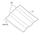
- the statement slip 13 when the statement slip 13 passes over the shutter 30, the statement slip 13 is bent (bent) in a direction perpendicular to the discharge direction by being sandwiched between the tip portion 31 and the recess 43 of the shutter 30. ) 130 is given. Since the statement slip 13 is obtained by cutting the continuous paper 8 wound in a roll shape by the cutter knife 11, it has a curl ridge in the discharge direction as shown in FIG. 13A. On the other hand, in the present embodiment, as shown in FIG. 13B, by ejecting while being sandwiched between the distal end portion 31 and the concave portion 43 of the shutter 30, a bend 130 is given in a direction perpendicular to the curl. , And can be discharged with the curl soot removed.
- FIG. 14 is a diagram for explaining a case where the card 71 is erroneously inserted into the statement slip processing apparatus 3-2 according to the second embodiment.
- the surface 31a of the distal end portion 31 enters the recess 43 more than the guide surface 41-2a of the upper guide 41-2.
- the card 71 cannot enter between the front end portion 31 and the upper guide 41-2, but hits the shutter 30 that closes the discharge conveyance path 12-2. That is, since the surface 31a of the tip 31 of the shutter 30 enters the recess 43 provided in the upper guide 41-2 and does not protrude from the guide surface 41-2a of the upper guide 41-2, it is extremely thick. Even when the thin card 71 is erroneously inserted, no gap is generated between the tip 31 and the upper guide 41-2.
- the statement slip 13 presses the distal end portion 31 of the shutter 30 to rotate the shutter 30 in the opening direction, thereby causing the distal end portion 31 and the upper guide 41-2 to move.
- the gap is generated and normally discharged from the statement slip discharge port 40 through the gap.
- the tip 31 enters the recess 43 of the upper guide 41-1, and does not protrude from the guide surface, so that no gap is generated. Intrusion into the inside of the card 71 can be prevented.
- the statement slip 13 when the statement slip 13 is ejected, it is ejected while being sandwiched between the tip portion 31 and the concave portion 43, thereby giving a deflection 130 in a direction perpendicular to the ejection direction of the statement slip 13 and curling the statement slip 13. Soot can be removed. Thereby, it becomes easy for a customer to receive the statement slip 13, and the operativity of the automatic transaction apparatus 1 improves.
- FIG. 10 In the perspective view shown in FIG. 10, an example in which there are two tip portions 31 and two concave portions 43 is shown. However, the present embodiment is not limited to this. For example, one tip portion 31 and one concave portion 43 are provided. There may be three or more.
- the distal end portion 31 of the shutter 30 is held in a state of entering the concave portion 43 provided in the upper guide 41-2.
- the discharge conveyance path 12-1 is closed, but the present embodiment is not limited to this.
- a specific description will be given with reference to FIG.
- FIG. 15 is a diagram showing a configuration around the discharge unit of a statement slip processing device 3-2 ′ according to a modification of the second embodiment.
- the statement slip processing device 3-2 ′ according to the modification can be rotated in the direction of closing or opening the discharge conveyance path 12-2 ′ for discharging the statement slip 13 to the statement slip discharge port 40. It has a shutter 30 '.
- the discharge conveyance path 12-2 ′ is formed by the upper guide 41 and the lower guide 42 ′, and conveys the statement slip 13 to the statement slip discharge port 40.
- the shutter 30 ′ is rotatable about the fulcrum 32 ′, and operates in the direction D4 by its own weight or the force of an elastic member such as a spring or a spring. It is held in contact with the 2 'lower guide 42'.
- the lower guide 42 ′ is provided with a concave portion 43 ′ in a portion where the tip portion 31 ′ contacts when closing the discharge conveyance path 12-2 ′. Accordingly, in the present embodiment, when the shutter 30 ′ operates in the D4 direction, the distal end portion 31 ′ of the shutter 30 ′ enters the concave portion 43 ′ of the lower guide 42 ′.
- the statement slip 13 When the statement slip is issued, the statement slip 13 is conveyed along the discharge conveyance path 12-2 'toward the statement slip discharge port 40.
- the statement slip 13 presses the front end portion 31 ′ of the shutter 30 ′ When the statement slip 13 presses the front end portion 31 ′ of the shutter 30 ′, the shutter 30 ′ rotates in the D3 direction to open the discharge conveyance path 12-2 ′, and the front end portion 31 ′ and the lower guide 42 ′ There is a gap between them.
- the statement slip 13 passes through the gap along the lower guide 42 ′, and is discharged from the statement slip outlet 40 while being pressed by the tip portion 31 ′.
- the magnetic card 7 is ejected from the card insertion / ejection port 4 adjacent to the statement slip ejection port 40 almost simultaneously with the ejection of the statement slip, but the description thereof is omitted here.
- the statement slip processing apparatus 3-2 may have a structure in which the concave portion 43 'is provided in the lower guide 42'. Further, since the tip 31 'enters the recess 43' provided in the lower guide 42 'and does not protrude from the guide surface of the lower guide 42', even if a very thin card is erroneously inserted Intrusion into the apparatus can be prevented without creating a gap between the tip 31 'and the lower guide 42'.
- the statement slip processing device 3 is arranged in the upward direction of the card processing device 2, but the present invention is not limited to this, for example, the statement slip processing device 3 is the card processing device 2. You may arrange
- the present invention is not limited to this. Specifically, the present invention can be applied to all media processing devices having a function of issuing a paper sheet or other paper-like media to customers, such as a ticket issuing processing device.
Landscapes
- Physics & Mathematics (AREA)
- General Physics & Mathematics (AREA)
- Engineering & Computer Science (AREA)
- Mechanical Engineering (AREA)
- Separation, Sorting, Adjustment, Or Bending Of Sheets To Be Conveyed (AREA)
- Conveying Record Carriers (AREA)
Abstract
所定の処理を行った紙状媒体(13)を排出する排出口(40)と、上部ガイド(41-1)と下部ガイド(42)により形成され、前記紙状媒体(13)を前記排出口(40)に搬送する搬送路(12-1)と、前記搬送路(12-1)を閉塞または開放する方向に回動可能なシャッタ(30)と、を備え、前記シャッタ(30)は、前記上部ガイド(41-1)または下部ガイド(42)と当接することで前記搬送路(12-1)を閉塞し、前記紙状媒体(13)の媒体排出時に、排出される前記紙状媒体(13)により押圧されることで前記搬送路(12-1)を開放する当接部(31)を有する、媒体処理装置。
Description
本発明は、媒体処理装置および自動取引装置に関する。
昨今、金融機関のATM(Automated teller machine)に代表される自動取引装置は、銀行、駅構内およびコンビニエンスストアなど、多様な場所に設置されている。顧客は、この自動取引装置に表示される表示画面において各種操作を行うことにより、入金、出金および残高照会などの取引を行うことができる。
このような自動取引装置は、取引情報が印刷されたレシートを排出するレシート排出口、および、磁気カードを挿入および排出するためカード挿入排出口を有する。レシート排出口およびカード挿入口は、例えば特許文献1に開示されているように、自動取引装置から排出されるカードおよびレシートを顧客が一挙動で受け取れるように、隣接して設けられるケースが多い。
しかし、レシート排出口とカード挿入排出口とが隣接する場合、顧客が磁気カードを誤ってレシート排出口に入れようとしてしまうことが想定される。このため、上記特許文献1では、レシートを搬送する搬送ガイドの内側に凸部を設け、凸部により形成される隙間を、レシートの厚みより広くカードの厚みより狭くなるように形成しているが、薄いカードの場合は誤挿入されてしまうという問題がある。
そこで、本発明は、上記問題に鑑みてなされたものであり、本発明の目的とするところは、紙状媒体の排出口への他媒体の誤挿入をより確実に防止することが可能な、新規かつ改良された媒体処理装置および自動取引装置を提供することにある。
上記課題を解決するために、本発明のある観点によれば、所定の処理を行った紙状媒体を排出する排出口と、ガイドにより形成され、前記紙状媒体を前記排出口に搬送する搬送路と、前記搬送路を閉塞または開放する方向に回動可能なシャッタと、を備え、前記シャッタは、前記ガイドと当接することで前記搬送路を閉塞し、前記紙状媒体の媒体排出時に、排出される前記紙状媒体により押圧されることで前記搬送路を開放する当接部を有する、媒体処理装置が提供される。
また、前記紙状媒体は、前記当接部により押さえつけられながら排出されてもよい。
また、前記ガイドは上部ガイドと下部ガイドから成り、前記上部ガイドまたは前記下部ガイドのうち、前記当接部が前記搬送路を閉塞する際に当接する部分に凹部が設けられ、前記当接部は、前記凹部と入れ子を形成することで前記搬送路を閉塞してもよい。
また、前記当接部は、前記搬送路を閉塞する状態の際、前記凹部に入り込み、ガイド面から突出しない形状とされてもよい。
また、前記紙状媒体は、前記当接部と前記凹部とに挟まれることにより撓みが与えられた状態で前記排出口から排出されてもよい。
また、前記シャッタより下流には、排出ローラおよび媒体センサのいずれも設けなくてもよい。
また、前記シャッタは、弾性部材により閉塞方向に回動されてもよい。
また、前記紙状媒体を排出する排出口は、カード状媒体の挿入排出口に近接して設けられてもよい。
また、本発明の他の観点によれば、所定の処理を行った紙状媒体を排出する排出口と、ガイドにより形成され、前記紙状媒体を前記排出口に搬送する搬送路と、前記搬送路を閉塞または開放する方向に回動可能なシャッタと、を有する媒体処理装置を備え、前記シャッタは、前記ガイドと当接することで前記搬送路を閉塞し、前記紙状媒体の媒体排出時に、排出される前記紙状媒体により押圧されることで前記搬送路を開放する当接部を有する、自動取引装置が提供される。
以上説明したように本発明によれば、紙状媒体の排出口への他媒体の誤挿入をより確実に防止することが可能である。
以下に添付図面を参照しながら、本発明の実施の形態について詳細に説明する。なお、本明細書及び図面において、実質的に同一の機能構成を有する構成要素については、同一の符号を付することにより重複説明を省略する。
本発明は、以下本明細書において詳細に説明するような多様な形態で実施され得る。また、各実施形態による媒体処理装置(明細票処理装置3)は、
A.所定の処理を行った紙状媒体(明細票13)を排出する排出口(明細票排出口40)と、
B.上部ガイドと下部ガイドにより形成され、前記紙状媒体を前記排出口に搬送する搬送路(排出搬送路12)と、
C.前記搬送路を閉塞または開放する方向に回動可能なシャッタ(30)と、
を備え、
D.前記シャッタは、前記上部ガイドまたは下部ガイドと当接することで前記搬送路を閉塞し、前記紙状媒体の媒体排出時に、排出される前記紙状媒体により押圧されることで前記搬送路を開放する当接部(先端部31)を有する。
A.所定の処理を行った紙状媒体(明細票13)を排出する排出口(明細票排出口40)と、
B.上部ガイドと下部ガイドにより形成され、前記紙状媒体を前記排出口に搬送する搬送路(排出搬送路12)と、
C.前記搬送路を閉塞または開放する方向に回動可能なシャッタ(30)と、
を備え、
D.前記シャッタは、前記上部ガイドまたは下部ガイドと当接することで前記搬送路を閉塞し、前記紙状媒体の媒体排出時に、排出される前記紙状媒体により押圧されることで前記搬送路を開放する当接部(先端部31)を有する。
このような明細票処理装置3について、まず明細票処理装置3を搭載する自動取引装置1を用いた自動取引システムの概要を説明してから、各実施形態を参照して説明する。
<1.自動取引システムの概要>
図1は、本発明の実施形態である自動取引システムの全体構成を示した説明図である。図1に示したように、自動取引システムは、複数の自動取引装置1、専用網62、および金融機関ホスト70を含む。
図1は、本発明の実施形態である自動取引システムの全体構成を示した説明図である。図1に示したように、自動取引システムは、複数の自動取引装置1、専用網62、および金融機関ホスト70を含む。
自動取引装置1は、金融機関の顧客による操作に基づいて金銭の取引を実行する顧客操作型端末である。この自動取引装置1は、金融機関の営業店、コンビニエンスストア、駅構内、ホテル、病院、アミューズメントパーク、飲食店、オフィスビルディングなどの多様な施設に設置される。
また、自動取引装置1は、カード挿入排出口4、明細票排出口40、操作表示部54、通帳挿入口56、および接客口58を備える。操作表示部54は、顧客による操作の誘導画面を表示する表示部および顧客操作を検出する顧客操作部としての機能を包含する。表示部としての機能は、例えば、CRT(Cathode Ray Tube)ディスプレイ装置、液晶ディスプレイ(LCD)装置、OLED(Organic Light Emitting Diode)装置により実現される。また、顧客操作部としての機能は例えばタッチパネルにより実現される。
なお、図1においては表示部および顧客操作部の機能が自動取引装置1において一体的に構成される例を示しているが、表示部および顧客操作部の機能は分離して構成されてもよい。
通帳挿入口56は顧客の通帳の挿入および排出を行う。また、接客口58は、顧客による紙幣の入金口、および顧客への紙幣の出金口としての機能を有する。
カード挿入排出口4は、顧客の磁気カードの挿入および排出を行うための開口部である。また、明細票排出口40は、取引情報が印刷された明細票(レシート)を排出するための開口部である。このカード挿入排出口4と明細票排出口40は、図1に示したように上下に隣接して設けられるので、顧客は、カード挿入排出口4から排出される磁気カードおよび明細票排出口40から排出されるレシートを一挙動で受け取ることが可能である。
専用網62は、金融機関のネットワークであり、例えばIP-VPN(Internet Protocol-Virtual Private Network)により構成される。金融機関ホスト70は、この専用網62を介して自動取引装置1と通信することができる。
金融機関ホスト70は、専用網62を介して自動取引装置1と通信することにより、各種取引を制御する。例えば、金融機関ホスト70は、自動取引装置1を操作する顧客の認証を行ったり、自動取引装置1において顧客により指示された入金や振込などの金銭取引(勘定の取引処理)を実行したりする。また、金融機関ホスト70は、口座番号、暗証番号、氏名、住所、年齢、生年月日、電話番号、職業、家族構成、年収、預金残高などの顧客情報(口座の元帳)を管理する。
本発明の実施形態は、上述した自動取引システムに含まれる自動取引装置1に関し、特に、自動取引装置1における明細票排出口40の周辺の構成に関する。そこで、以下、自動取引装置1に搭載されるカード処理装置2および明細票処理装置3の基本構成を説明した後に、本発明の各実施形態について詳細に説明する。
<2.基本構成>
(構成)
図2は、本発明の一実施形態による自動取引装置1に搭載されるカード処理装置2および明細票処理装置3の基本構成を示した図である。図2に示したように、本実施形態による自動取引装置1は、カード処理装置2、および明細票処理装置3を有する。カード処理装置2と明細票処理装置3は、図2に示すように、カード挿入排出口4と明細票排出口40が上下方向に近接するよう上下方向に並べて配置される。なお、カード処理装置2および明細票処理装置3は一体になった1つのユニットとして構成される。
(構成)
図2は、本発明の一実施形態による自動取引装置1に搭載されるカード処理装置2および明細票処理装置3の基本構成を示した図である。図2に示したように、本実施形態による自動取引装置1は、カード処理装置2、および明細票処理装置3を有する。カード処理装置2と明細票処理装置3は、図2に示すように、カード挿入排出口4と明細票排出口40が上下方向に近接するよう上下方向に並べて配置される。なお、カード処理装置2および明細票処理装置3は一体になった1つのユニットとして構成される。
カード処理装置2は、カード挿入排出口4、リーダライタ部5、および印字部6を有する。リーダライタ部5は、カード状媒体である磁気カード7上のデータの読み取りおよび書込みを行う。リーダライタ部5により読み取られたデータは、自動取引装置1の制御部により取得され、制御部は、リーダライタ部5から取得したデータに基づいて取引を制御する。また、カード状媒体が、白濁方式やロイコ方式によるリライトカードの場合、印字部6により取引結果が印字される。
一方、明細票処理装置3は、連続用紙8が巻回された用紙ロール9、サーマルヘッドおよびプラテンを含む印字部10、カッタナイフ11、排出搬送路12、取込搬送路14、回収部15を有する。
印字部10は、サーマルヘッドにより、プラテン上に搬送された連続用紙8に所定の取引情報を印字する。カッタナイフ11は、連続用紙8の取引情報が印字された部分を、一枚の紙葉状媒体である明細票13に切断する。切断された明細票13は、排出搬送路12において、明細票排出口40に向けてD1方向に搬送される。
取込搬送路14は、顧客の受取忘れ等により、一定時間経過しても明細票排出口40から除去されなかった明細票13をD2方向に搬送する。回収部15は、取込搬送路14で搬送された明細票13を回収する。
(動作)
続いて、以上説明した構成を有するカード処理装置2および明細票処理装置3の取引動作について説明する。顧客が、カード挿入排出口4から、キャッシュカード、振込カード等の磁気カード7を挿入すると、カード挿入排出口4とリーダライタ部5の間に設けられたフィードローラが回転して磁気カード7をリーダライタ部5に搬送する。そして、リーダライタ部5は、カード状媒体である磁気カード7上のデータを読取る。制御部はリーダライタ部5により読み取ったデータに基づいて取引を制御する。
続いて、以上説明した構成を有するカード処理装置2および明細票処理装置3の取引動作について説明する。顧客が、カード挿入排出口4から、キャッシュカード、振込カード等の磁気カード7を挿入すると、カード挿入排出口4とリーダライタ部5の間に設けられたフィードローラが回転して磁気カード7をリーダライタ部5に搬送する。そして、リーダライタ部5は、カード状媒体である磁気カード7上のデータを読取る。制御部はリーダライタ部5により読み取ったデータに基づいて取引を制御する。
また、制御部は、リーダライタ部5により取引情報を磁気カード7に書き込む機能も有する。なお挿入されたカードへの書き込みは、リーダライタ部5による書込みに限定されず、さらに上流に設けられた印字部6に搬送して印字部6による印字で行ってもよい。
また、制御部は、カード処理装置2における磁気カード7への書き込み動作に並行して、明細票処理装置3において明細票13の発行動作を行う。具体的には、制御部は、印字部10により連続用紙8に取引情報を印字する。連続用紙8は、プラテンが回転することにより、明細票排出口40の方向に所定量送られ、カッタナイフ11により明細票13として切断される。明細票13は、排出搬送路12を明細票排出口40に向けてD1方向に搬送される。
そして、明細票13は、磁気カード7がカード挿入排出口4から排出されると略同時に、明細票排出口40から排出される。明細票排出口40は、カード挿入排出口4と上下方向に近接して配置されているので、図3に示すように、明細票13は、カード挿入排出口4から排出される磁気カード7と重なった状態で、明細票排出口40からD1方向に排出される。これにより、顧客は、明細票13と磁気カード7を一挙動で受け取ることができる。
(問題点)
しかしながら、明細票排出口40とカード挿入排出口4が上下方向に近接した配置になっている場合、顧客が誤って磁気カード7を明細票排出口40に挿入してしまう場合がある。この際の問題点について図4を参照して説明する。
しかしながら、明細票排出口40とカード挿入排出口4が上下方向に近接した配置になっている場合、顧客が誤って磁気カード7を明細票排出口40に挿入してしまう場合がある。この際の問題点について図4を参照して説明する。
図4は、比較例による明細票排出口20に磁気カード7を誤挿入した場合について説明するための図である。図4に示すように、明細票排出口20に磁気カード7を誤挿入した場合、排出搬送路の上流に設けられた媒体センサ16に検知される。
媒体センサ16の検知結果からは、検知対象が紙状媒体である明細票か、カード状媒体である磁気カードかを識別することができないので、制御部は、顧客が受け取り忘れた明細票と誤認識し、フィードローラ17を回転して磁気カード7を取り込んでしまう。取り込まれた磁気カード7は、取込搬送路14を経由して回収部15に回収される。
つまり、顧客の磁気カード7は、明細票処理装置3の内部に収納されてしまい、顧客に返却することができなくなってしまう。また、紙状媒体である明細票13と比較して硬度が高い磁気カード7が明細票処理装置3に侵入することにより、磁気カード7が搬送路近傍の部品を破損させてしまう場合もある。
そこで、上記事情を一着眼点にして本実施形態による自動取引装置を創作するに至った。本実施形態による自動取引装置は、紙状媒体の排出口への他媒体の誤挿入をより確実に防止することが可能である。以下、このような本発明の各実施形態について順次詳細に説明する。
<3.各実施形態の詳細な説明>
[3-1.第1の実施形態]
(構成)
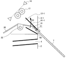
図5は、第1の実施形態による明細票処理装置3-1の排出部周辺の構成を示した図である。第1の実施形態による明細票処理装置3-1は、明細票排出口40へ明細票13を排出する排出搬送路12-1を閉塞または開放する方向に回動可能なシャッタ30を有する。排出搬送路12-1は、上部ガイド41-1と下部ガイド42により形成され、明細票13を明細票排出口40に搬送する。
[3-1.第1の実施形態]
(構成)
図5は、第1の実施形態による明細票処理装置3-1の排出部周辺の構成を示した図である。第1の実施形態による明細票処理装置3-1は、明細票排出口40へ明細票13を排出する排出搬送路12-1を閉塞または開放する方向に回動可能なシャッタ30を有する。排出搬送路12-1は、上部ガイド41-1と下部ガイド42により形成され、明細票13を明細票排出口40に搬送する。
シャッタ30は、図5に示すように、支点32を軸として回動可能な構造であって、自重、または、ばねやスプリング等の弾性部材の力によりD3方向に付勢され、先端部31が排出搬送路12-1の上部ガイド41-1に接触した状態で保持される。また、シャッタ30は、フィードローラ17および媒体センサ16よりも下流(明細票排出口40側)に設けられており、シャッタ30より下流には、排出ローラ(フィードローラ)や媒体センサのいずれも設けられていない。
また、シャッタ30の先端部31は、シャッタ30の両端部のうち、支点32より明細票排出口40側の端部に設けられる。また、先端部31は、シャッタ30の端部を明細票排出口40側に歪曲させて形成している。
(動作)
このような構成を有する明細票処理装置3-1による明細票発行動作について図6を参照して説明する。図6は、第1の実施形態による明細票処理装置3-1の明細票発行動作について説明するための図である。
このような構成を有する明細票処理装置3-1による明細票発行動作について図6を参照して説明する。図6は、第1の実施形態による明細票処理装置3-1の明細票発行動作について説明するための図である。
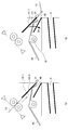
図6(a)に示すように、明細票発行時には、明細票13が排出ローラによって排出搬送路12-1を明細票排出口40の方向に搬送される。明細票13は、シャッタ30上を通過する際、図6(b)に示すように、シャッタ30の先端部31を押圧することで、シャッタ30がD4方向に回動して排出搬送路12-1が開放し、先端部31と上部ガイド41-1の間に隙間C1が生じる。
そして、明細票13は、隙間C1を上部ガイド41-1に沿って通過し、先端部31により押さえつけられながら明細票排出口40から排出される。なお明細票の排出と略同時に、明細票排出口40と近接するカード挿入排出口4から磁気カード7が排出されるが、ここでは説明を省略する。
このように、シャッタ30が設けられていても、明細票13は通常通り明細票排出口40から排出され得る。
一方、明細票排出口40から誤って磁気カード7が挿入された場合について、図7を参照して説明する。図7は、第1の実施形態による明細票処理装置3-1に磁気カード7が誤挿入された場合について説明するための図である。
図7に示すように、明細票排出口40から磁気カード7が誤挿入された場合、磁気カード7は、排出搬送路12-1を閉塞するシャッタ30の先端部31に接触し、奥に押し入ることができない。すなわち、シャッタ30の端部を排出口側に歪曲して形成された先端部31の端部と上部ガイド41-1の間隔G1が、磁気カード7の厚さ未満であるので、磁気カード7は、先端部31に突き当たる。また、顧客が磁気カード7をさらに押し込んだ場合、先端部31は磁気カード7に押されてD3方向に動作しようとするが、先端部31は上部ガイド41-1に接触して動くことができないので、磁気カード7をこれ以上奥に押し入ることはできない。
(効果)
以上説明したように、第1の実施形態によれば、明細票13は、シャッタ30の先端部31を押圧することでシャッタ30をD4方向に回動させて先端部31と上部ガイド41-1との間に隙間を発生させ、当該隙間を通って明細票排出口40から外部に排出される。一方、明細票排出口40から磁気カード7が誤挿入された場合、磁気カード7はシャッタ30の先端部31に突き当たる。磁気カード7により先端部31を押しても、先端部31は上部ガイド41-1に接触して動くことができないので、磁気カード7の内部への侵入を防止することができる。
以上説明したように、第1の実施形態によれば、明細票13は、シャッタ30の先端部31を押圧することでシャッタ30をD4方向に回動させて先端部31と上部ガイド41-1との間に隙間を発生させ、当該隙間を通って明細票排出口40から外部に排出される。一方、明細票排出口40から磁気カード7が誤挿入された場合、磁気カード7はシャッタ30の先端部31に突き当たる。磁気カード7により先端部31を押しても、先端部31は上部ガイド41-1に接触して動くことができないので、磁気カード7の内部への侵入を防止することができる。
また、シャッタ30の先端部31は媒体センサ16よりも下流(明細票排出口40側)に設けられているので、誤挿入された磁気カード7を媒体センサ16で検知し、取り忘れの明細票13と誤認識して装置内部に回収してしまうことを防止することもできる。
さらに、シャッタ30はフィードローラ17よりも下流に設けられているので、誤挿入された、硬度が高い磁気カード7によってフィードローラ17の表面が破損してしまうことも防止することができる。
なお、図5を参照して説明した本実施形態による明細票処理装置3-1の構成では、シャッタ30の先端部31が上部ガイド41-1に接触した状態で保持されることで排出搬送路12-1を閉塞しているが、本実施形態はこれに限定されない。例えば、シャッタ30の先端部31が下部ガイド42に接触した状態で保持されることで排出搬送路12-1を閉塞する構成であってもよい。この場合、フィードローラ17から搬送される明細票13は、先端部31を押圧することでシャッタ30をD3方向に回動させ、下部ガイド42と先端部31の間に隙間を生じさせて、当該隙間を通って明細票排出口40に搬送される。
[3-2.第2の実施形態]
次に、第2の実施形態による明細票処理装置3-2について説明する。上述した第1の実施形態による明細票処理装置3-1では、極めて厚さの薄いカードや紙片が上部ガイド41-1に沿わせて明細票排出口40から挿入された場合、装置内部に侵入させてしまう恐れがある。以下、図8を参照して具体的に説明する。
次に、第2の実施形態による明細票処理装置3-2について説明する。上述した第1の実施形態による明細票処理装置3-1では、極めて厚さの薄いカードや紙片が上部ガイド41-1に沿わせて明細票排出口40から挿入された場合、装置内部に侵入させてしまう恐れがある。以下、図8を参照して具体的に説明する。
図8は、明細票排出口40から装置内部への極めて厚さの薄いカードの誤挿入について説明するための図である。図8に示すように、第1の実施形態による排出搬送路12-1を形成する上部ガイド41-1のガイド面は平坦であるので、厚さの薄いカード71が上部ガイド41-1に沿って明細票排出口40から挿入されると、先端部31をD4方向に押圧できてしまう。そして、先端部31がD4方向に動作すると、先端部31と上部ガイド41-1との間に隙間C1が発生し、カード71が当該隙間C1から装置内部に侵入してしまう恐れがある。そこで、このような極めて厚さの薄いカードや紙片の侵入もより確実に防止する第2の実施形態による明細票処理装置3-2を提案する。
(構成)
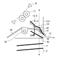
図9は、第2の実施形態による明細票処理装置3-2の排出部周辺の構成を示した図である。第2の実施形態による明細票処理装置3-2は、明細票排出口40へ明細票13を排出する排出搬送路12-2を閉塞または開放する方向に回動可能なシャッタ30を有する。排出搬送路12-2は、上部ガイド41-2と下部ガイド42により形成され、明細票13を明細票排出口40に搬送する。
図9は、第2の実施形態による明細票処理装置3-2の排出部周辺の構成を示した図である。第2の実施形態による明細票処理装置3-2は、明細票排出口40へ明細票13を排出する排出搬送路12-2を閉塞または開放する方向に回動可能なシャッタ30を有する。排出搬送路12-2は、上部ガイド41-2と下部ガイド42により形成され、明細票13を明細票排出口40に搬送する。
シャッタ30は、第1の実施形態と同様に、支点32を軸として回動可能な構造であって、自重、または、ばねやスプリング等の弾性部材の力によりD3方向に付勢され、先端部31が排出搬送路12-2の上部ガイド41-2に接触した状態で保持される。
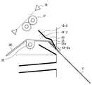
さらに、本実施形態では、上部ガイド41-2において、先端部31が排出搬送路12-2を閉塞する際に当接する部分に凹部43を設ける。これにより、本実施形態では、シャッタ30がD3方向に動作した場合に、シャッタ30の先端部31が上部ガイド41-2の凹部43に入り込む構造となる。先端部31が凹部43に入り込んだ際、図9に示すように、先端部31の面31aは、上部ガイド41-2のガイド面41-2aよりも凹部43内部に入り込む。
このような構造を有する本実施形態による明細票排出部の斜視図を図10に示す。図10に示すように、本実施形態によるシャッタ30に設けられる先端部31は、シャッタ30の両側辺がそれぞれ延長されて形成された複数の先端部31であってもよく、この場合、上部ガイド41-2に設けられる凹部43も複数個設けられる。シャッタ30は、支点32を軸として回動可能であって、図10に示すように、複数の先端部31が排出搬送路12-2の上部ガイド41-2に設けられた複数の凹部43にそれぞれ入り込む状態で保持されることで、排出搬送路12-2を閉塞する。
(動作)
このような構成を有する明細票処理装置3-2による明細票発行動作について図11を参照して説明する。図11は、第2の実施形態による明細票処理装置3-2の明細票発行動作について説明するための図である。
このような構成を有する明細票処理装置3-2による明細票発行動作について図11を参照して説明する。図11は、第2の実施形態による明細票処理装置3-2の明細票発行動作について説明するための図である。
図11に示すように、明細票発行時には、明細票13が排出搬送路12-2を明細票排出口40の方向に搬送される。明細票13は、シャッタ30上を通過する際、シャッタ30の先端部31を押圧することで、シャッタ30がD4方向に回動して排出搬送路12-1が開放し、先端部31と上部ガイド41-2の間に隙間C2が生じる。
そして、明細票13は、隙間C2を上部ガイド41-2に沿って通過し、先端部31により押さえつけられながら明細票排出口40から排出される。なお明細票の排出と略同時に、明細票排出口40と近接するカード挿入排出口4から磁気カード7が排出されるが、ここでは説明を省略する。
このように、シャッタ30が設けられていても、明細票13は通常通り明細票排出口40から排出され得る。また、明細票13は、先端部31と凹部43に挟まれることにより撓みが与えられた状態で明細票排出口40から排出される。明細票13に与えられる撓みについて図12の断面図を用いて説明する。図12は、図11に示す明細票排出部のA-A断面図である。
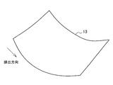
図12に示すように、明細票13がシャッタ30上を通過する際、シャッタ30の先端部31と凹部43に挟まれることで、明細票13には、排出方向に垂直な方向に撓み(屈曲)130が与えられる。明細票13は、ロール状に巻かれた連続用紙8がカッタナイフ11により切断されたものであるので、図13Aに示すように、排出方向にカール癖を有している。これに対し、本実施形態では、シャッタ30の先端部31と凹部43で挟みながら排出することで、図13Bに示すように、カールに垂直な方向に撓み130が与えられるので、明細票13は、カール癖が除去された状態で排出され得る。
一方、明細票排出口40から誤って極めて厚さの薄いカード71が挿入された場合について、図14を参照して説明する。図14は、第2の実施形態による明細票処理装置3-2にカード71が誤挿入された場合について説明するための図である。
図14に示すように、明細票排出口40からカード71が誤挿入された場合、先端部31の面31aは上部ガイド41-2のガイド面41-2aよりも凹部43内部に入り込んでいるので、カード71は先端部31と上部ガイド41-2の間に進入することができず、排出搬送路12-2を閉塞するシャッタ30に突き当たる。すなわち、シャッタ30の先端部31の面31aが上部ガイド41-2に設けられた凹部43に入り込み、上部ガイド41-2のガイド面41-2aから突出しない形状とされるので、極めて厚さの薄いカード71が誤挿入された場合でも先端部31と上部ガイド41-2の間に隙間は発生しない。
(効果)
以上説明したように、第2の実施形態によれば、明細票13は、シャッタ30の先端部31を押圧することでシャッタ30を開放方向に回動させて先端部31と上部ガイド41-2の隙間を発生させ、当該隙間を通って明細票排出口40から外部に正常に排出される。一方、明細票排出口40から極めて厚さの薄いカード71が誤挿入された場合でも、先端部31は上部ガイド41-1の凹部43に入り込み、ガイド面から突出していないので、隙間は発生せず、カード71の内部への侵入を防止することができる。
以上説明したように、第2の実施形態によれば、明細票13は、シャッタ30の先端部31を押圧することでシャッタ30を開放方向に回動させて先端部31と上部ガイド41-2の隙間を発生させ、当該隙間を通って明細票排出口40から外部に正常に排出される。一方、明細票排出口40から極めて厚さの薄いカード71が誤挿入された場合でも、先端部31は上部ガイド41-1の凹部43に入り込み、ガイド面から突出していないので、隙間は発生せず、カード71の内部への侵入を防止することができる。
また、本実施形態では、明細票13を排出する際、先端部31と凹部43で挟みながら排出することで、明細票13の排出方向に垂直な方向に撓み130を与えて明細票13のカール癖を除去することができる。これにより、顧客は明細票13を受け取り易くなり、自動取引装置1の操作性が向上する。
なお、図10に示した斜視図では、先端部31と凹部43がそれぞれ2つある例を示したが、本実施形態はこれに限定されず、例えば先端部31と凹部43がそれぞれ1つであってもよいし、3つ以上であってもよい。
また、図9を参照して説明した本実施形態による明細票処理装置3-2の構成では、シャッタ30の先端部31が上部ガイド41-2に設けられた凹部43に入り込む状態で保持されることで排出搬送路12-1を閉塞しているが、本実施形態はこれに限定されない。以下、図15を参照して具体的に説明する。
(変形例)
図15は、第2の実施形態の変形例による明細票処理装置3-2’の排出部周辺の構成を示した図である。図15に示すように、変形例による明細票処理装置3-2’は、明細票排出口40へ明細票13を排出する排出搬送路12-2’を閉塞または開放する方向に回動可能なシャッタ30’を有する。排出搬送路12-2’は、上部ガイド41と下部ガイド42’により形成され、明細票13を明細票排出口40に搬送する。
図15は、第2の実施形態の変形例による明細票処理装置3-2’の排出部周辺の構成を示した図である。図15に示すように、変形例による明細票処理装置3-2’は、明細票排出口40へ明細票13を排出する排出搬送路12-2’を閉塞または開放する方向に回動可能なシャッタ30’を有する。排出搬送路12-2’は、上部ガイド41と下部ガイド42’により形成され、明細票13を明細票排出口40に搬送する。
シャッタ30’は、支点32’を軸として回動可能な構造であって、自重、または、ばねやスプリング等の弾性部材の力によりD4方向に動作し、先端部31’が排出搬送路12-2’の下部ガイド42’に接触した状態で保持される。
さらに、本実施形態では、下部ガイド42’において、先端部31’が排出搬送路12-2’を閉塞する際に当接する部分に凹部43’を設ける。これにより、本実施形態では、シャッタ30’がD4方向に動作した場合に、シャッタ30’の先端部31’が下部ガイド42’の凹部43’に入り込む構造となる。
明細票発行時には、明細票13が排出搬送路12-2’を明細票排出口40の方向に搬送される。明細票13がシャッタ30’の先端部31’を押圧することで、シャッタ30’がD3方向に回動して排出搬送路12-2’を開放し、先端部31’と下部ガイド42’の間に隙間が生じる。明細票13は、当該隙間を下部ガイド42’に沿って通過し、先端部31’により押さえつけられながら明細票排出口40から排出される。なお明細票の排出と略同時に、明細票排出口40と近接するカード挿入排出口4から磁気カード7が排出されるが、ここでは説明を省略する。
このように、第2の実施形態による明細票処理装置3-2は、下部ガイド42’に凹部43’が設けられる構造であってもよい。また、先端部31’が下部ガイド42’に設けられた凹部43’に入り込み、下部ガイド42’のガイド面から突出しない形状とされるので、極めて厚さの薄いカードが誤挿入された場合でも、先端部31’と下部ガイド42’の間に隙間を生じさせず、装置内部に侵入することを防止することができる。
<4.まとめ>
以上説明したように、本発明の第1~第2の実施形態によれば、明細票排出口40への磁気カードの誤挿入をより確実に防止することが可能である。
以上説明したように、本発明の第1~第2の実施形態によれば、明細票排出口40への磁気カードの誤挿入をより確実に防止することが可能である。
なお、添付図面を参照しながら本発明の好適な実施形態について詳細に説明したが、本発明はかかる例に限定されない。本発明の属する技術の分野における通常の知識を有する者であれば、特許請求の範囲に記載された技術的思想の範疇内において、各種の変更例または修正例に想到し得ることは明らかであり、これらについても、当然に本発明の技術的範囲に属するものと了解される。
例えば、上述した各実施形態では、明細票処理装置3がカード処理装置2の上方向に配置されているが、本発明はこれに限定されず、例えば明細票処理装置3がカード処理装置2の下方向に配置されていてもよい。
また、上述した各実施形態では、金銭の取引を実行する顧客操作型端末に搭載され、取引情報を印字した明細票を発行する明細票(発行)処理装置3に適用した例を説明したが、本発明はこれに限定されない。具体的には、例えば乗車券発行処理装置等、明細票他の紙状媒体を顧客に発行する機能を有する媒体処理装置全般に適用可能である。
1 自動取引装置
2 カード処理装置
3、3-1、3-2、3-2’ 明細票処理装置
4 カード挿入排出口
5 リーダライタ部
6 印字部
7 磁気カード
71 カード
8 連続用紙
9 用紙ロール
10 印字部
11 カッタナイフ
12、12-1、12-2、12-2’ 排出搬送路
14 取込搬送路
15 回収部
16 媒体センサ
17 フィードローラ
30 シャッタ
31 先端部
32 支点
40 明細票排出口
41、41-1、41-2 上部ガイド
42、42’ 下部ガイド
43、43’ 凹部
54 操作表示部
56 通帳挿入口
58 接客口
62 専用網
70 金融機関ホスト
130 撓み
D1~D4 方向
2 カード処理装置
3、3-1、3-2、3-2’ 明細票処理装置
4 カード挿入排出口
5 リーダライタ部
6 印字部
7 磁気カード
71 カード
8 連続用紙
9 用紙ロール
10 印字部
11 カッタナイフ
12、12-1、12-2、12-2’ 排出搬送路
14 取込搬送路
15 回収部
16 媒体センサ
17 フィードローラ
30 シャッタ
31 先端部
32 支点
40 明細票排出口
41、41-1、41-2 上部ガイド
42、42’ 下部ガイド
43、43’ 凹部
54 操作表示部
56 通帳挿入口
58 接客口
62 専用網
70 金融機関ホスト
130 撓み
D1~D4 方向
Claims (9)
- 所定の処理を行った紙状媒体を排出する排出口と、
ガイドにより形成され、前記紙状媒体を前記排出口に搬送する搬送路と、
前記搬送路を閉塞または開放する方向に回動可能なシャッタと、
を備え、
前記シャッタは、前記ガイドと当接することで前記搬送路を閉塞し、前記紙状媒体の媒体排出時に、排出される前記紙状媒体により押圧されることで前記搬送路を開放する当接部を有する、媒体処理装置。 - 前記紙状媒体は、前記当接部により押さえつけられながら排出される、請求項1に記載の媒体処理装置。
- 前記ガイドは上部ガイドと下部ガイドから成り、前記上部ガイドまたは前記下部ガイドのうち、前記当接部が前記搬送路を閉塞する際に当接する部分に凹部が設けられ、
前記当接部は、前記凹部と入れ子を形成することで前記搬送路を閉塞する、請求項1に記載の媒体処理装置。 - 前記当接部は、前記搬送路を閉塞する状態の際、前記凹部に入り込み、ガイド面から突出しない形状とされる、請求項3に記載の媒体処理装置。
- 前記紙状媒体は、前記当接部と前記凹部とに挟まれることにより撓みが与えられた状態で前記排出口から排出される、請求項3に記載の媒体処理装置。
- 前記シャッタより下流には、排出ローラおよび媒体センサのいずれも設けない、請求項1に記載の媒体処理装置。
- 前記シャッタは、弾性部材により閉塞方向に回動される、請求項1に記載の媒体処理装置。
- 前記紙状媒体を排出する排出口は、カード状媒体の挿入排出口に近接して設けられる、請求項1に記載の媒体処理装置。
- 所定の処理を行った紙状媒体を排出する排出口と、ガイドにより形成され、前記紙状媒体を前記排出口に搬送する搬送路と、前記搬送路を閉塞または開放する方向に回動可能なシャッタと、を有する媒体処理装置を備え、
前記シャッタは、ガイドと当接することで前記搬送路を閉塞し、前記紙状媒体の媒体排出時に、排出される前記紙状媒体により押圧されることで前記搬送路を開放する当接部を有する、自動取引装置。
Priority Applications (1)
| Application Number | Priority Date | Filing Date | Title |
|---|---|---|---|
| CN201480023905.9A CN105144253B (zh) | 2013-08-30 | 2014-04-11 | 介质处理装置以及自动交易装置 |
Applications Claiming Priority (2)
| Application Number | Priority Date | Filing Date | Title |
|---|---|---|---|
| JP2013179246A JP6102642B2 (ja) | 2013-08-30 | 2013-08-30 | 媒体処理装置および自動取引装置 |
| JP2013-179246 | 2013-08-30 |
Publications (1)
| Publication Number | Publication Date |
|---|---|
| WO2015029488A1 true WO2015029488A1 (ja) | 2015-03-05 |
Family
ID=52586071
Family Applications (1)
| Application Number | Title | Priority Date | Filing Date |
|---|---|---|---|
| PCT/JP2014/060534 Ceased WO2015029488A1 (ja) | 2013-08-30 | 2014-04-11 | 媒体処理装置および自動取引装置 |
Country Status (3)
| Country | Link |
|---|---|
| JP (1) | JP6102642B2 (ja) |
| CN (1) | CN105144253B (ja) |
| WO (1) | WO2015029488A1 (ja) |
Families Citing this family (3)
| Publication number | Priority date | Publication date | Assignee | Title |
|---|---|---|---|---|
| CN107749132B (zh) * | 2017-11-15 | 2023-05-12 | 湖南长城医疗科技有限公司 | 凭条出纸口防插卡机构 |
| JP7314578B2 (ja) * | 2019-04-05 | 2023-07-26 | 沖電気工業株式会社 | 自動取引装置 |
| JP7400325B2 (ja) * | 2019-10-15 | 2023-12-19 | 富士フイルムビジネスイノベーション株式会社 | 用紙搬送装置および画像形成装置 |
Citations (4)
| Publication number | Priority date | Publication date | Assignee | Title |
|---|---|---|---|---|
| JPH0341375U (ja) * | 1989-09-01 | 1991-04-19 | ||
| JPH076865U (ja) * | 1993-07-02 | 1995-01-31 | グローリー工業株式会社 | 伝票発行部構造 |
| JP3056350B2 (ja) * | 1993-06-30 | 2000-06-26 | 沖電気工業株式会社 | 自動取引装置 |
| JP2013061913A (ja) * | 2011-09-15 | 2013-04-04 | Oki Electric Ind Co Ltd | 自動取引装置 |
Family Cites Families (4)
| Publication number | Priority date | Publication date | Assignee | Title |
|---|---|---|---|---|
| JPH0731326Y2 (ja) * | 1989-03-31 | 1995-07-19 | グローリー工業株式会社 | 紙幣識別機の紙幣受入れ装置 |
| JPH0393978U (ja) * | 1990-01-18 | 1991-09-25 | ||
| JP4348866B2 (ja) * | 2001-01-12 | 2009-10-21 | 沖電気工業株式会社 | 通帳処理装置 |
| JP2007133786A (ja) * | 2005-11-11 | 2007-05-31 | Toyo Network Systems Co Ltd | 金銭取扱い装置 |
-
2013
- 2013-08-30 JP JP2013179246A patent/JP6102642B2/ja active Active
-
2014
- 2014-04-11 WO PCT/JP2014/060534 patent/WO2015029488A1/ja not_active Ceased
- 2014-04-11 CN CN201480023905.9A patent/CN105144253B/zh not_active Expired - Fee Related
Patent Citations (4)
| Publication number | Priority date | Publication date | Assignee | Title |
|---|---|---|---|---|
| JPH0341375U (ja) * | 1989-09-01 | 1991-04-19 | ||
| JP3056350B2 (ja) * | 1993-06-30 | 2000-06-26 | 沖電気工業株式会社 | 自動取引装置 |
| JPH076865U (ja) * | 1993-07-02 | 1995-01-31 | グローリー工業株式会社 | 伝票発行部構造 |
| JP2013061913A (ja) * | 2011-09-15 | 2013-04-04 | Oki Electric Ind Co Ltd | 自動取引装置 |
Also Published As
| Publication number | Publication date |
|---|---|
| CN105144253A (zh) | 2015-12-09 |
| CN105144253B (zh) | 2018-08-31 |
| JP6102642B2 (ja) | 2017-03-29 |
| JP2015049571A (ja) | 2015-03-16 |
Similar Documents
| Publication | Publication Date | Title |
|---|---|---|
| US9640008B2 (en) | Cash transaction machine | |
| JP6102642B2 (ja) | 媒体処理装置および自動取引装置 | |
| JP5607008B2 (ja) | 自動取引装置 | |
| US11055971B1 (en) | Bendable anti-skimming plate for a card reader | |
| JP5142740B2 (ja) | 自動取引装置 | |
| JP6245029B2 (ja) | 媒体取引装置 | |
| JP2012137922A (ja) | 通帳取扱装置および通帳取扱方法 | |
| JP5658573B2 (ja) | 取引処理装置、および取引処理システム | |
| JP6183105B2 (ja) | 媒体処理装置および自動取引装置 | |
| JP5729444B2 (ja) | 自動取引装置 | |
| KR100526580B1 (ko) | 지폐류 입출금기의 일시저장장치 | |
| JP6561561B2 (ja) | 自動取引装置 | |
| JP6696217B2 (ja) | 冊子状媒体処理装置 | |
| JP6583045B2 (ja) | 自動取引装置 | |
| JP4753598B2 (ja) | 自動取引装置 | |
| JP5664361B2 (ja) | 紙葉類取込装置及び自動取引装置 | |
| JPH06290332A (ja) | 自動取引方式 | |
| KR101932189B1 (ko) | 매체 입금장치 및 금융기기 | |
| JP5454611B2 (ja) | 印刷装置及び自動取引装置 | |
| JP2018092537A (ja) | 紙幣処理装置 | |
| JP4478611B2 (ja) | 顧客受付用端末及びその制御プログラム及び顧客受付システム | |
| JPS5853386B2 (ja) | 通帳処理装置 | |
| WO2015198801A1 (ja) | 紙幣取引装置 | |
| JPH1186091A (ja) | 自動取引装置 | |
| JPH04163689A (ja) | 自動取引方式 |
Legal Events
| Date | Code | Title | Description |
|---|---|---|---|
| WWE | Wipo information: entry into national phase |
Ref document number: 201480023905.9 Country of ref document: CN |
|
| 121 | Ep: the epo has been informed by wipo that ep was designated in this application |
Ref document number: 14840269 Country of ref document: EP Kind code of ref document: A1 |
|
| NENP | Non-entry into the national phase |
Ref country code: DE |
|
| 122 | Ep: pct application non-entry in european phase |
Ref document number: 14840269 Country of ref document: EP Kind code of ref document: A1 |