WO2015029217A1 - 燃料配管用防音カバー - Google Patents
燃料配管用防音カバー Download PDFInfo
- Publication number
- WO2015029217A1 WO2015029217A1 PCT/JP2013/073330 JP2013073330W WO2015029217A1 WO 2015029217 A1 WO2015029217 A1 WO 2015029217A1 JP 2013073330 W JP2013073330 W JP 2013073330W WO 2015029217 A1 WO2015029217 A1 WO 2015029217A1
- Authority
- WO
- WIPO (PCT)
- Prior art keywords
- cover
- cover body
- clamp
- fuel pipe
- fuel piping
- Prior art date
- Legal status (The legal status is an assumption and is not a legal conclusion. Google has not performed a legal analysis and makes no representation as to the accuracy of the status listed.)
- Ceased
Links
Images


Classifications
-
- F—MECHANICAL ENGINEERING; LIGHTING; HEATING; WEAPONS; BLASTING
- F02—COMBUSTION ENGINES; HOT-GAS OR COMBUSTION-PRODUCT ENGINE PLANTS
- F02M—SUPPLYING COMBUSTION ENGINES IN GENERAL WITH COMBUSTIBLE MIXTURES OR CONSTITUENTS THEREOF
- F02M37/00—Apparatus or systems for feeding liquid fuel from storage containers to carburettors or fuel-injection apparatus; Arrangements for purifying liquid fuel specially adapted for, or arranged on, internal-combustion engines
- F02M37/0011—Constructional details; Manufacturing or assembly of elements of fuel systems; Materials therefor
- F02M37/0017—Constructional details; Manufacturing or assembly of elements of fuel systems; Materials therefor related to fuel pipes or their connections, e.g. joints or sealings
-
- F—MECHANICAL ENGINEERING; LIGHTING; HEATING; WEAPONS; BLASTING
- F16—ENGINEERING ELEMENTS AND UNITS; GENERAL MEASURES FOR PRODUCING AND MAINTAINING EFFECTIVE FUNCTIONING OF MACHINES OR INSTALLATIONS; THERMAL INSULATION IN GENERAL
- F16L—PIPES; JOINTS OR FITTINGS FOR PIPES; SUPPORTS FOR PIPES, CABLES OR PROTECTIVE TUBING; MEANS FOR THERMAL INSULATION IN GENERAL
- F16L55/00—Devices or appurtenances for use in, or in connection with, pipes or pipe systems
- F16L55/02—Energy absorbers; Noise absorbers
- F16L55/033—Noise absorbers
-
- F—MECHANICAL ENGINEERING; LIGHTING; HEATING; WEAPONS; BLASTING
- F16—ENGINEERING ELEMENTS AND UNITS; GENERAL MEASURES FOR PRODUCING AND MAINTAINING EFFECTIVE FUNCTIONING OF MACHINES OR INSTALLATIONS; THERMAL INSULATION IN GENERAL
- F16L—PIPES; JOINTS OR FITTINGS FOR PIPES; SUPPORTS FOR PIPES, CABLES OR PROTECTIVE TUBING; MEANS FOR THERMAL INSULATION IN GENERAL
- F16L57/00—Protection of pipes or objects of similar shape against external or internal damage or wear
-
- F—MECHANICAL ENGINEERING; LIGHTING; HEATING; WEAPONS; BLASTING
- F02—COMBUSTION ENGINES; HOT-GAS OR COMBUSTION-PRODUCT ENGINE PLANTS
- F02M—SUPPLYING COMBUSTION ENGINES IN GENERAL WITH COMBUSTIBLE MIXTURES OR CONSTITUENTS THEREOF
- F02M2200/00—Details of fuel-injection apparatus, not otherwise provided for
- F02M2200/09—Fuel-injection apparatus having means for reducing noise
Definitions
- the present invention relates to a soundproof cover for a fuel pipe that is attached to a fuel pipe of an automobile.
- Patent Document 1 discloses a protector for protection attached to a resin tube serving as a fuel pipe.
- a protector main body attached to the outer periphery of the resin tube and a positioning fixing portion provided at an end of the protector main body are integrally formed of polypropylene or the like.
- the cover body is formed of a foam such as urethane, and a resin clip for sandwiching the fuel pipe is integrally coupled to the inside of the cover body.
- the cover main body may be broken because the adhesion strength between the clip and the cover main body is weaker than the pipe removal load.
- an object of the present invention is to provide a sound insulation cover for fuel pipes that can be removed from the fuel pipe without damaging the cover body and is excellent in reliability.
- the invention according to claim 1 is a sound insulation cover for a fuel pipe comprising a cover body covering the fuel pipe and a clip coupled to the cover body and capable of sandwiching the fuel pipe.
- the clip is formed of a clamp part that is arranged inside the cover body and can hold the fuel pipe, and a grip part that is connected to the clamp part and exposed to the outside of the cover body.
- a positioning recess for positioning the clamp portion is provided on the inner surface of the cover body.
- the clamp part and the grip part are formed separately and are connected to each other through the cover body.
- the cover main body is pre-compressed in a connected state of the clamp portion and the gripping portion.
- the positioning recess is provided, so that the clamp portion can be properly positioned within the cover body.
- the invention described in claim 3 in addition to the effect of claim 1 or 2, there is no need to deform the cover body when the clip is assembled to the cover body, and there is no possibility of breaking the cover body.
- the invention of claim 4 in addition to the effect of claim 3, even if there is an error in the connecting part between the clamp part and the grip part, this can be absorbed, and the cover main body can be suitably used without the rattling.
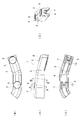
- FIG. 1 is a perspective view showing an example of a sound insulation cover for fuel piping (hereinafter abbreviated as “sound insulation cover”)
- FIG. 2 is an explanatory view thereof
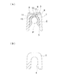
- FIG. 3 is a cross-sectional view taken along lines AA and BB.
- the soundproof cover 1 includes a cover main body 2 and clips 3 and 3 arranged at two positions of the cover main body 2.
- the cover body 2 is a foam (here, urethane) having a U-shaped cross section that is bent along a metal fuel pipe and has a groove 4 extending over its entire length.
- the mounting portions of the clips 3 and 3 in the groove 4 are positioning recesses 5 and 5 in which the interval and depth of the groove are increased. Is formed.
- the clip 3 includes a clamp portion 7 located inside the cover main body 2 (inside the groove 4) and a grip portion 8 connected to the clamp portion 7 and exposed to the outside (plane side) of the cover main body 2.
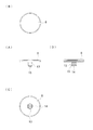
- the clamp portion 7 is made of a resin in which both ends of a C-shaped plate body are bent outward, and a cylindrical portion 9 having a through hole 10 is formed at the upper center portion. Is done.
- a ridge 11 having a mortar-shaped taper portion 12 at the top is provided on the other hand, as shown in FIG.
- the gripping portion 8 is made of a resin having a disk shape, and a boss 13 having a slit 14 formed in the diameter direction protrudes from the center of the lower surface.
- a barb 15 is formed on the outer periphery.
- the outer diameter of the boss 13 is slightly smaller than the inner diameter narrowed by the protrusion 11 in the through hole 10 of the clamp portion 7.
- the soundproof cover 1 configured as described above has the clamp portion 7 in the positioning recess 5 of the cover body 2, and the C-shaped central axis is parallel to the center of the groove 4.
- the cylindrical portion 9 is inserted into the through hole 6 from below.
- the boss 13 of the grip portion 8 is inserted into the through hole 10 of the tubular portion 9 from the upper side of the cover body 2, the tip of the boss 13 is guided by the tapered portion 12 of the protrusion 11 and elastically contracts. And penetrate the ridge 11.
- the boss 13 gets over the ridge 11, the boss 13 is elastically restored and the barb 15 is locked to the lower surface of the barb 11, so that the boss 13 is snap-fit with the tubular portion 9 in a state of being prevented from coming off. Therefore, the clamp part 7 is connected to the grip part 8 through the cover body 2, and the clip 3 is integrated with the cover body 2. In this state, the grip 8 is exposed on the upper surface of the cover body 2.
- the clamp portion 7 is fitted in the positioning recess 5 of the cover body 2, the C-shaped central axis is held in a direction parallel to the center of the groove 4.
- the height of the cylindrical portion 9 is smaller than the length of the through hole 6 of the cover main body 2 (the thickness of the cover main body 2), in the state where the grip portion 8 is connected to the clamp portion 7, the clamp portion The cover body 2 is pre-compressed between the outer surface of 7 and the lower surface of the gripping portion 8 so that the clip 3 does not rattle even if there is an error in the connecting portion.
- the snap-fit coupling between the clamp part 7 and the grip part 8 is a shape design in which the removal load between the clamp part 7 and the grip part 8 is larger than the removal load between the clamp part 7 and the fuel pipe. I am doing.
- the soundproof cover 1 when the soundproof cover 1 is attached to the fuel pipe, the fuel pipe is applied to the clamp portion 7 of each clip 3 when the cover main body 2 is applied so that the fuel pipe is fitted in the groove 4 of the cover main body 2.
- the clip 3 When the clip 3 is pushed in as it comes into contact, the fuel pipe P is sandwiched between the clamp portions 7 as shown in FIG. Accordingly, the cover main body 2 is mounted along the fuel pipe P via the clips 3 and 3.
- the clamp portion 7 when removing the soundproof cover 1, if the grip 3 exposed on the upper surface of the cover body 2 is gripped and the clip 3 is pulled, the clamp portion 7 is removed from the fuel pipe P according to the setting of the extraction load described above. Can be removed. At this time, since the cover main body 2 is not pulled directly, there is no possibility that the cover main body 2 may be broken due to an applied load.
- the clip 3 is arrange
- the cover main body 2 By forming from the gripping part 8 exposed to the outside, the cover main body 2 can be detached from the fuel pipe P without fear of damage, and the reliability is excellent.
- the separate clip 3 is assembled to the molded cover body 2 here, there is no concern that the cover body 2 will adhere to the clip 3 as in the case of integral molding, and the cover body 2 may be torn during demolding. The risk of doing so is eliminated.
- the clamp portion 7 can be properly positioned in the cover body 2. Furthermore, by forming the clamp part 7 and the grip part 8 separately and connecting them through the cover body 2, there is no need to deform the cover body 2 when the clip 3 is assembled to the cover body 2, Again, there is no risk of breaking the cover body 2. And since the cover main body 2 is pre-compressed in the connection state of the clamp part 7 and the holding part 8, even if there is an error in the connection part, this can be absorbed, and the cover main body 2 It is preferably integrated.
- two clips are provided on the cover body, but one may be used, or three or more may be used.
- the snap fit coupling between the clamp part and the grip part is a cylindrical part on the clamp part side and a boss on the grip part side, but they may be reversed.
- the structure of the clamp part and the grip part is not limited to the above-described form.
- the gripping part can be gripped from the outside of the cover main body, it is not limited to a disk shape, and a cutout may be provided on the outer periphery, a quadrangle, a polygon, or the like. It can also be provided. Therefore, depending on the shape of the gripping portion, the clip does not necessarily have to be composed of two parts, and the clamp portion and the gripping portion may be integrated as long as the clip can be assembled to the cover body.
Landscapes
- Engineering & Computer Science (AREA)
- General Engineering & Computer Science (AREA)
- Mechanical Engineering (AREA)
- Chemical & Material Sciences (AREA)
- Combustion & Propulsion (AREA)
- Cooling, Air Intake And Gas Exhaust, And Fuel Tank Arrangements In Propulsion Units (AREA)
- Protection Of Pipes Against Damage, Friction, And Corrosion (AREA)
- Clamps And Clips (AREA)
- Supports For Pipes And Cables (AREA)
- Pipe Accessories (AREA)
Abstract
Description
一方、防音を目的としたカバーの場合、カバー本体がウレタン等の発泡体で形成され、このカバー本体の内側に、燃料配管を挟持するための樹脂製のクリップが一体に結合されている。
請求項2に記載の発明は、請求項1の構成において、カバー本体の内面に、クランプ部の位置決めを行う位置決め凹部を設けたことを特徴とするものである。
請求項3に記載の発明は、請求項1又は2の構成において、クランプ部と把持部とを別体に形成して、カバー本体越しに両者を連結したことを特徴とするものである。
請求項4に記載の発明は、請求項3の構成において、クランプ部と把持部との連結状態でカバー本体を予圧縮することを特徴とするものである。
請求項2に記載の発明によれば、請求項1の効果に加えて、位置決め凹部を設けたことで、カバー本体内でのクランプ部の位置決めを適正に行うことができる。
請求項3に記載の発明によれば、請求項1又は2の効果に加えて、クリップをカバー本体に組み付ける際にカバー本体を変形させる必要がなく、カバー本体を破いたりするおそれがなくなる。
請求項4に記載の発明によれば、請求項3の効果に加えて、クランプ部と把持部との連結部に誤差があってもこれを吸収でき、クリップががたつくことなくカバー本体と好適に一体化される。
図1は、燃料配管用防音カバー(以下「防音カバー」と略称する。)の一例を示す斜視図、図2はその説明図、図3はA-A線及びB-B線断面図である。防音カバー1は、カバー本体2と、カバー本体2の二カ所に配置されるクリップ3,3とを含んでなる。
カバー本体2は、金属製の燃料配管に沿って屈曲形成され、全長に亘って溝4を形成した横断面U字状の発泡体(ここではウレタン)となっている。また、溝4におけるクリップ3,3の装着部位は、溝の間隔及び深さが大きくなる位置決め凹部5,5となっており、各位置決め凹部5の底となる部位には、透孔6がそれぞれ形成されている。
まずクランプ部7は、図4にも示すように、C字状に形成した板体の両端を外向きに折り曲げた樹脂製で、中央上部には、貫通孔10を有する筒状部9が形成される。貫通孔10の内周面には、上部をすり鉢状のテーパ部12とした突条11が周設されている。
一方、把持部8は、図5にも示すように円板状を有した樹脂製で、下面中心には、直径方向にスリット14を形成したボス13が突設されており、ボス13の先端外周には、返し15が形成されている。このボス13の外径は、クランプ部7の貫通孔10において突条11によって絞られる内径よりも僅かに小さくなっている。
また、筒状部9の高さはカバー本体2の透孔6の長さ(カバー本体2の厚み)よりも小さくなっているため、クランプ部7に把持部8を連結した状態では、クランプ部7の外面と把持部8の下面との間でカバー本体2は予圧縮され、連結部に誤差があってもクリップ3ががたつかないようになっている。さらに、クランプ部7と把持部8とのスナップフィット結合は、クランプ部7と燃料配管との間の抜去荷重より、クランプ部7と把持部8との間の抜去荷重の方が大きくなる形状設計をしている。
一方、防音カバー1を取り外す際には、カバー本体2の上面に露出している把持部8を把持してクリップ3を引っ張れば、先述した抜去荷重の設定により、燃料配管Pからクランプ部7を外すことができる。このとき、カバー本体2を直接引っ張ることがないため、カバー本体2に荷重が加わって破断したりするおそれは生じない。
特にここでは、成形したカバー本体2に別体のクリップ3を組み付けているので、一体成形の場合のようにクリップ3にカバー本体2が付着する懸念がなくなり、脱型時にカバー本体2が破れたりするおそれが解消される。
さらに、クランプ部7と把持部8とを別体に形成して、カバー本体2越しに両者を連結したことで、クリップ3をカバー本体2に組み付ける際にカバー本体2を変形させる必要がなく、ここでもカバー本体2を破いたりするおそれがなくなる。
そして、クランプ部7と把持部8との連結状態でカバー本体2を予圧縮するようにしているので、連結部に誤差があってもこれを吸収でき、クリップ3ががたつくことなくカバー本体2と好適に一体化される。
また、クランプ部と把持部とのスナップフィット結合は、クランプ部側が筒状部、把持部側がボスとなっているが、互いに逆にしてもよい。勿論スナップフィット結合に限らず、両部品の連結が可能であれば他の構造も採用可能である。
さらに、クランプ部や把持部の構造も上記形態に限らない。特に把持部は、カバー本体の外部から把持可能であれば、円板状に限らず、外周に切欠を設けたり、四角形や多角形等としたりしてもよいし、把持しやすいように突起を設けることもできる。
よって、把持部の形状によってはクリップは必ずしも2部品から構成する必要はなく、カバー本体への組み付けが可能であればクランプ部と把持部とが一体化されたものであってもよい。
Claims (4)
- 燃料配管を覆うカバー本体と、そのカバー本体と結合され、燃料配管を挟持可能なクリップとからなる燃料配管用防音カバーであって、
前記クリップを、前記カバー本体の内側に配置されて前記燃料配管を挟持可能なクランプ部と、前記クランプ部と接続されて前記カバー本体の外側に露出する把持部とから形成したことを特徴とする燃料配管用防音カバー。 - 前記カバー本体の内面に、前記クランプ部の位置決めを行う位置決め凹部を設けたことを特徴とする請求項1に記載の燃料配管用防音カバー。
- 前記クランプ部と前記把持部とを別体に形成して、前記カバー本体越しに両者を連結したことを特徴とする請求項1又は2に記載の燃料配管用防音カバー。
- 前記クランプ部と前記把持部との連結状態で前記カバー本体を予圧縮することを特徴とする請求項3に記載の燃料配管用防音カバー。
Priority Applications (4)
| Application Number | Priority Date | Filing Date | Title |
|---|---|---|---|
| PCT/JP2013/073330 WO2015029217A1 (ja) | 2013-08-30 | 2013-08-30 | 燃料配管用防音カバー |
| JP2015533893A JP5868560B2 (ja) | 2013-08-30 | 2013-08-30 | 燃料配管用防音カバー |
| CN201380078671.3A CN105452747B (zh) | 2013-08-30 | 2013-08-30 | 燃料配管用隔音罩 |
| US14/971,075 US9528477B2 (en) | 2013-08-30 | 2015-12-16 | Soundproof cover for fuel pipe |
Applications Claiming Priority (1)
| Application Number | Priority Date | Filing Date | Title |
|---|---|---|---|
| PCT/JP2013/073330 WO2015029217A1 (ja) | 2013-08-30 | 2013-08-30 | 燃料配管用防音カバー |
Related Child Applications (1)
| Application Number | Title | Priority Date | Filing Date |
|---|---|---|---|
| US14/971,075 Continuation US9528477B2 (en) | 2013-08-30 | 2015-12-16 | Soundproof cover for fuel pipe |
Publications (1)
| Publication Number | Publication Date |
|---|---|
| WO2015029217A1 true WO2015029217A1 (ja) | 2015-03-05 |
Family
ID=52585832
Family Applications (1)
| Application Number | Title | Priority Date | Filing Date |
|---|---|---|---|
| PCT/JP2013/073330 Ceased WO2015029217A1 (ja) | 2013-08-30 | 2013-08-30 | 燃料配管用防音カバー |
Country Status (4)
| Country | Link |
|---|---|
| US (1) | US9528477B2 (ja) |
| JP (1) | JP5868560B2 (ja) |
| CN (1) | CN105452747B (ja) |
| WO (1) | WO2015029217A1 (ja) |
Citations (2)
| Publication number | Priority date | Publication date | Assignee | Title |
|---|---|---|---|---|
| JPS6226761U (ja) * | 1985-08-01 | 1987-02-18 | ||
| JP2002168373A (ja) * | 2000-11-28 | 2002-06-14 | Suzuki Motor Corp | 配管カバーの取付構造 |
Family Cites Families (13)
| Publication number | Priority date | Publication date | Assignee | Title |
|---|---|---|---|---|
| CH588660A5 (ja) * | 1975-12-16 | 1977-06-15 | Deria Destra | |
| JPS6226761A (ja) | 1985-07-26 | 1987-02-04 | Shin Kobe Electric Mach Co Ltd | 密閉形アルカリ電池の相互接続方法 |
| JPS6256897A (ja) * | 1985-09-06 | 1987-03-12 | 株式会社日立製作所 | 安全容器と原子炉容器の組立方法 |
| JPH10213037A (ja) * | 1997-01-31 | 1998-08-11 | Suzuki Motor Corp | 配管のクランプ装置 |
| DE10119892C2 (de) * | 2001-04-24 | 2003-04-03 | Skf Ab | Deckel, insbesondere zur Dämpfung des Geräusches eines Verbrennungsmotors |
| JP3833909B2 (ja) * | 2001-07-11 | 2006-10-18 | 東海ゴム工業株式会社 | 防音カバー |
| US6581720B1 (en) * | 2001-11-30 | 2003-06-24 | Dana Corporation | Noise attenuating insulated heat shield |
| FR2835035B1 (fr) * | 2002-01-22 | 2004-08-20 | Fabien Cacciani | Support de pose pour canalisation et circuits divers, domestiques ou industriels |
| US20050082111A1 (en) * | 2003-10-18 | 2005-04-21 | Sika Technology Ag | Acoustic baffle |
| JP2005282836A (ja) * | 2004-03-31 | 2005-10-13 | Tokai Rubber Ind Ltd | 樹脂チューブ用プロテクタ |
| US7441533B1 (en) * | 2007-05-07 | 2008-10-28 | Gm Global Technology Operations, Inc. | Cover assembly for an internal combustion engine |
| FR2922290B1 (fr) * | 2007-10-15 | 2012-09-21 | Delattre Ind Dev Did | Dispositif destine a monter un conduit sur un support |
| WO2012059840A1 (en) * | 2010-11-01 | 2012-05-10 | Koninklijke Philips Electronics N.V. | Gas delivery conduit management system |
-
2013
- 2013-08-30 JP JP2015533893A patent/JP5868560B2/ja active Active
- 2013-08-30 WO PCT/JP2013/073330 patent/WO2015029217A1/ja not_active Ceased
- 2013-08-30 CN CN201380078671.3A patent/CN105452747B/zh active Active
-
2015
- 2015-12-16 US US14/971,075 patent/US9528477B2/en active Active
Patent Citations (2)
| Publication number | Priority date | Publication date | Assignee | Title |
|---|---|---|---|---|
| JPS6226761U (ja) * | 1985-08-01 | 1987-02-18 | ||
| JP2002168373A (ja) * | 2000-11-28 | 2002-06-14 | Suzuki Motor Corp | 配管カバーの取付構造 |
Also Published As
| Publication number | Publication date |
|---|---|
| US20160097357A1 (en) | 2016-04-07 |
| JP5868560B2 (ja) | 2016-02-24 |
| CN105452747B (zh) | 2018-10-16 |
| CN105452747A (zh) | 2016-03-30 |
| JPWO2015029217A1 (ja) | 2017-03-02 |
| US9528477B2 (en) | 2016-12-27 |
Similar Documents
| Publication | Publication Date | Title |
|---|---|---|
| EP2749778B1 (en) | Clip | |
| JP5168694B2 (ja) | クリップ | |
| JP6399383B2 (ja) | 防振クランプ | |
| US20140166825A1 (en) | Clamp | |
| JP6966263B2 (ja) | プロテクタ | |
| JP2012095434A (ja) | バンドクリップ | |
| WO2013114466A1 (ja) | 超音波センサモジュールの取り付け構造 | |
| JP2010159843A (ja) | ボルト用クリップ | |
| JP2008190682A (ja) | 防振クランプ装置 | |
| JP5868560B2 (ja) | 燃料配管用防音カバー | |
| JP2003143741A (ja) | フラットケーブル用ストッパ及びフラットケーブルの取付け構造 | |
| JP2019202732A5 (ja) | ||
| JP2018201284A (ja) | 車体固定用クリップ及びワイヤハーネス | |
| JP5910581B2 (ja) | 結束バンドの取付構造 | |
| JP5181889B2 (ja) | 樹脂容器構造 | |
| JP5182161B2 (ja) | ワイヤハーネス用クランプ | |
| JP2009185934A (ja) | 樹脂部品の取付構造 | |
| JP6322105B2 (ja) | アース端子ユニット | |
| WO2017204108A1 (ja) | バンド具及び複合バンド具 | |
| JP5910281B2 (ja) | クリップ及びクリップ付きワイヤーハーネス | |
| JP2016032412A (ja) | ワイヤハーネス用プロテクタ | |
| JP5488259B2 (ja) | バンド式コルゲートクランプ | |
| JP5776536B2 (ja) | 水密部材付きバンドクリップ、ワイヤーハーネス及びバンドクリップ用水密部材 | |
| JP2013219858A (ja) | 経路維持部材付コルゲートチューブ | |
| JP2006067676A (ja) | ハーネスの支持構造 |
Legal Events
| Date | Code | Title | Description |
|---|---|---|---|
| WWE | Wipo information: entry into national phase |
Ref document number: 201380078671.3 Country of ref document: CN |
|
| 121 | Ep: the epo has been informed by wipo that ep was designated in this application |
Ref document number: 13892545 Country of ref document: EP Kind code of ref document: A1 |
|
| ENP | Entry into the national phase |
Ref document number: 2015533893 Country of ref document: JP Kind code of ref document: A |
|
| NENP | Non-entry into the national phase |
Ref country code: DE |
|
| 122 | Ep: pct application non-entry in european phase |
Ref document number: 13892545 Country of ref document: EP Kind code of ref document: A1 |