WO2015025670A1 - 空気入りタイヤ - Google Patents
空気入りタイヤ Download PDFInfo
- Publication number
- WO2015025670A1 WO2015025670A1 PCT/JP2014/069456 JP2014069456W WO2015025670A1 WO 2015025670 A1 WO2015025670 A1 WO 2015025670A1 JP 2014069456 W JP2014069456 W JP 2014069456W WO 2015025670 A1 WO2015025670 A1 WO 2015025670A1
- Authority
- WO
- WIPO (PCT)
- Prior art keywords
- groove
- tire
- radial direction
- main groove
- siping
- Prior art date
Links
Images


Classifications
-
- B—PERFORMING OPERATIONS; TRANSPORTING
- B60—VEHICLES IN GENERAL
- B60C—VEHICLE TYRES; TYRE INFLATION; TYRE CHANGING; CONNECTING VALVES TO INFLATABLE ELASTIC BODIES IN GENERAL; DEVICES OR ARRANGEMENTS RELATED TO TYRES
- B60C11/00—Tyre tread bands; Tread patterns; Anti-skid inserts
- B60C11/03—Tread patterns
- B60C11/13—Tread patterns characterised by the groove cross-section, e.g. for buttressing or preventing stone-trapping
- B60C11/1353—Tread patterns characterised by the groove cross-section, e.g. for buttressing or preventing stone-trapping with special features of the groove bottom
-
- B—PERFORMING OPERATIONS; TRANSPORTING
- B60—VEHICLES IN GENERAL
- B60C—VEHICLE TYRES; TYRE INFLATION; TYRE CHANGING; CONNECTING VALVES TO INFLATABLE ELASTIC BODIES IN GENERAL; DEVICES OR ARRANGEMENTS RELATED TO TYRES
- B60C11/00—Tyre tread bands; Tread patterns; Anti-skid inserts
- B60C11/03—Tread patterns
- B60C11/0327—Tread patterns characterised by special properties of the tread pattern
-
- B—PERFORMING OPERATIONS; TRANSPORTING
- B60—VEHICLES IN GENERAL
- B60C—VEHICLE TYRES; TYRE INFLATION; TYRE CHANGING; CONNECTING VALVES TO INFLATABLE ELASTIC BODIES IN GENERAL; DEVICES OR ARRANGEMENTS RELATED TO TYRES
- B60C11/00—Tyre tread bands; Tread patterns; Anti-skid inserts
- B60C11/03—Tread patterns
- B60C11/04—Tread patterns in which the raised area of the pattern consists only of continuous circumferential ribs, e.g. zig-zag
- B60C11/042—Tread patterns in which the raised area of the pattern consists only of continuous circumferential ribs, e.g. zig-zag further characterised by the groove cross-section
- B60C11/047—Tread patterns in which the raised area of the pattern consists only of continuous circumferential ribs, e.g. zig-zag further characterised by the groove cross-section the groove bottom comprising stone trapping protection elements, e.g. ribs
-
- B—PERFORMING OPERATIONS; TRANSPORTING
- B60—VEHICLES IN GENERAL
- B60C—VEHICLE TYRES; TYRE INFLATION; TYRE CHANGING; CONNECTING VALVES TO INFLATABLE ELASTIC BODIES IN GENERAL; DEVICES OR ARRANGEMENTS RELATED TO TYRES
- B60C11/00—Tyre tread bands; Tread patterns; Anti-skid inserts
- B60C11/03—Tread patterns
- B60C11/12—Tread patterns characterised by the use of narrow slits or incisions, e.g. sipes
- B60C11/1236—Tread patterns characterised by the use of narrow slits or incisions, e.g. sipes with special arrangements in the tread pattern
- B60C11/125—Tread patterns characterised by the use of narrow slits or incisions, e.g. sipes with special arrangements in the tread pattern arranged at the groove bottom
-
- B—PERFORMING OPERATIONS; TRANSPORTING
- B60—VEHICLES IN GENERAL
- B60C—VEHICLE TYRES; TYRE INFLATION; TYRE CHANGING; CONNECTING VALVES TO INFLATABLE ELASTIC BODIES IN GENERAL; DEVICES OR ARRANGEMENTS RELATED TO TYRES
- B60C11/00—Tyre tread bands; Tread patterns; Anti-skid inserts
- B60C11/03—Tread patterns
- B60C11/0327—Tread patterns characterised by special properties of the tread pattern
- B60C2011/0334—Stiffness
-
- B—PERFORMING OPERATIONS; TRANSPORTING
- B60—VEHICLES IN GENERAL
- B60C—VEHICLE TYRES; TYRE INFLATION; TYRE CHANGING; CONNECTING VALVES TO INFLATABLE ELASTIC BODIES IN GENERAL; DEVICES OR ARRANGEMENTS RELATED TO TYRES
- B60C11/00—Tyre tread bands; Tread patterns; Anti-skid inserts
- B60C11/03—Tread patterns
- B60C2011/0337—Tread patterns characterised by particular design features of the pattern
- B60C2011/0339—Grooves
- B60C2011/0341—Circumferential grooves
- B60C2011/0353—Circumferential grooves characterised by width
-
- B—PERFORMING OPERATIONS; TRANSPORTING
- B60—VEHICLES IN GENERAL
- B60C—VEHICLE TYRES; TYRE INFLATION; TYRE CHANGING; CONNECTING VALVES TO INFLATABLE ELASTIC BODIES IN GENERAL; DEVICES OR ARRANGEMENTS RELATED TO TYRES
- B60C11/00—Tyre tread bands; Tread patterns; Anti-skid inserts
- B60C11/03—Tread patterns
- B60C2011/0337—Tread patterns characterised by particular design features of the pattern
- B60C2011/0339—Grooves
- B60C2011/0341—Circumferential grooves
- B60C2011/0355—Circumferential grooves characterised by depth
-
- B—PERFORMING OPERATIONS; TRANSPORTING
- B60—VEHICLES IN GENERAL
- B60C—VEHICLE TYRES; TYRE INFLATION; TYRE CHANGING; CONNECTING VALVES TO INFLATABLE ELASTIC BODIES IN GENERAL; DEVICES OR ARRANGEMENTS RELATED TO TYRES
- B60C11/00—Tyre tread bands; Tread patterns; Anti-skid inserts
- B60C11/03—Tread patterns
- B60C11/13—Tread patterns characterised by the groove cross-section, e.g. for buttressing or preventing stone-trapping
- B60C11/1353—Tread patterns characterised by the groove cross-section, e.g. for buttressing or preventing stone-trapping with special features of the groove bottom
- B60C2011/1361—Tread patterns characterised by the groove cross-section, e.g. for buttressing or preventing stone-trapping with special features of the groove bottom with protrusions extending from the groove bottom
Definitions
- the present invention relates to a pneumatic tire in which drainage performance and noise performance are improved in a well-balanced manner.
- a pneumatic tire provided with a main groove extending continuously in the tire circumferential direction is known.
- the present invention has been devised in view of the actual situation as described above, and provides a pneumatic tire in which drainage performance and noise performance are improved in a well-balanced manner on the basis of improving the shape of the groove bottom of the main groove.
- the main purpose is to do.
- the present invention is a pneumatic tire in which at least one main groove extending continuously in a tire circumferential direction is provided in a tread portion, and the main groove has one of the cross sections perpendicular to the groove center line.
- a first groove wall extending inward in the tire radial direction from the tread surface, a second groove wall extending inward in the tire radial direction from the other tread surface, and an inner end of the first groove wall in the tire radial direction and the A groove bottom including a protruding portion that is connected to the inner end of the second groove wall in the tire radial direction and protrudes outward in the radial direction of the tire; and the protruding portion is continuous along the main groove; and
- the width of the main groove in the direction perpendicular to the groove center line is 50% to 100% of the groove width of the main groove, and the inner end of the first groove wall and the inner end of the second groove wall
- the outermost apex of the protruding portion in the tire radial direction is located on the groove center line of the main groove.
- the main groove extends linearly in the tire circumferential direction.
- the projecting portion is provided with siping extending along the groove center line of the main groove.
- the depth of the siping is 50% to 100% of a height in a radial direction of the tire from the virtual groove bottom of the protruding portion at a position where the siping is provided. Is desirable.
- the siping is provided on the inner side in the tire axial direction or on the tire equator than the intermediate position in the width direction of the protruding portion.
- At least one main groove extending continuously in the tire circumferential direction is provided in the tread portion.
- the main groove has a first groove wall extending inward in the tire radial direction from one tread tread surface, a second groove wall extending inward in the tire radial direction from the other tread tread surface in a cross section perpendicular to the groove center line, And a groove bottom including a projecting portion that is connected to the inner end of the first groove wall in the tire radial direction and the inner end of the second groove wall in the tire radial direction and protrudes outward in the tire radial direction.
- Such protrusions increase the rigidity of the groove bottom and suppress the vibration of the groove bottom. Therefore, the air column resonance is reduced and the noise performance is improved.
- the protruding portion is continuous along the main groove, and the width in the direction perpendicular to the groove center line of the main groove is 50% to 100% of the groove width of the main groove. Thereby, the rigidity of the groove bottom of the main groove is enhanced in a wide range.
- the cross-sectional area of the protrusion is 3% to 15% of the cross-sectional area of the main groove.
- Such a protrusion increases the rigidity of the groove bottom of the main groove while suppressing a decrease in the groove volume. Therefore, the pneumatic tire of the present invention improves drainage performance and noise performance with a good balance.
- FIG. 2 is a cross-sectional view taken along a line AA in FIG. It is a perspective view of the AA part of FIG.
- FIG. 3 is an enlarged view of a protruding portion in FIG. 2.
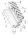
- FIG. 1 is a developed view of a tread portion showing an embodiment of the present invention.
- the pneumatic tire of the present embodiment (hereinafter sometimes simply referred to as “tire”) is suitably used as a pneumatic tire for passenger cars, for example.
- the tread portion 2 of the tire is provided with at least one main groove 3 extending continuously in the tire circumferential direction.
- the main groove 3 of the present embodiment includes a pair of center main grooves 4 extending on both sides of the tire equator C and a pair of shoulder main grooves 5 extending on the outer side in the tire axial direction of the center main groove 4.
- the tread portion 2 of the present embodiment includes a center land portion 6 divided by a pair of center main grooves 4, a pair of middle land portions 7 divided by the center main groove 4 and the shoulder main grooves 5, and a shoulder main A pair of shoulder land portions 8 that are divided by the groove 5 and the ground contact Te are provided.
- the shape of the tread portion 2 is not limited to such an aspect, and the main groove 3 may include, for example, a portion extending on the tire equator C. Further, each land portion 6 to 8 may be provided with a lateral groove, a lug groove, or the like extending in the tire axial direction.
- the “ground contact end” is a normal load loaded state in which a normal load is loaded on a normal rim that is assembled with a normal rim and filled with a normal internal pressure, and a normal load is applied to a flat surface with a camber angle of 0 °. Is determined as the ground contact position on the outermost side in the tire axial direction. In the normal state, the distance in the tire axial direction between the ground contact ends Te and Te is determined as the tread ground contact width TW. When there is no notice in particular, the dimension of each part of a tire, etc. are values measured in this normal state.
- the “regular rim” is a rim that is defined for each tire in the standard system including the standard on which the tire is based, and is “standard rim” for JATMA, “Design Rim” for TRA, In the case of ETRTO, it is “Measuring” Rim.
- Regular internal pressure is the air pressure that each standard defines for each tire in the standard system including the standard on which the tire is based.
- “JATMA” is the “highest air pressure”
- TRA is “TIRE” LOAD LIMITS The maximum value described in AT “VARIOUS” COLD “INFLATION” PRESSURES ”, or“ INFLATION PRESSURE ”in ETRTO.
- the normal internal pressure is 180 kPa.
- Regular load is a load determined by each standard for each tire in the standard system including the standard on which the tire is based.
- JATMA “maximum load capacity”, for TRA, “TIRE” LOAD
- the normal load is a load corresponding to 88% of the load.
- Both the main grooves 4 and 5 of the present embodiment extend linearly along the tire circumferential direction. Such main grooves 4 and 5 smoothly discharge the water in the grooves to the rear in the tire rotation direction, and increase the rigidity in the tire circumferential direction of the land portions 6 to 8.
- the main groove 3 may extend in a zigzag shape or a wave shape.
- the groove width W1 of each main groove 3 can be variously determined according to the custom. In order to increase the rigidity of each land portion 6 to 8 while ensuring the drainage performance, the groove width W1 of each main groove 3 is preferably 2.0% to 8.0% of the tread ground contact width TW, for example. .
- FIG. 2 shows the AA cross section of FIG. 1 as a cross-sectional view of the center main groove 4.
- FIG. 3 shows a perspective view of FIG. 2 and 3
- the center main groove 4 has a first groove wall 10, a second groove wall 11, and a groove bottom 12 in a cross section perpendicular to the groove center line G1.
- the “groove center line” is a line passing through the center of the groove width, and the position in the tire radial direction is not particularly limited.
- the first groove wall 10 extends inward in the tire radial direction from the tread surface 6A of the center land portion 6.
- the first groove wall 10 of the present embodiment has a first portion 10A that is inclined at an angle ⁇ 1 with respect to the normal line n of the tread tread 6A, and is smoothly connected to the first portion 10A and at an angle ⁇ 2 that is larger than the first portion 10A. And an inclined second portion 10B.
- the inner end 10t on the groove center line G1 side of the second portion 10B is the inner end 10i of the first groove wall 10 in the tire radial direction.
- the second groove wall 11 extends inward in the tire radial direction from the tread surface 7A of the middle land portion 7. Similar to the first groove wall 10, the second groove wall 11 of the present embodiment includes a first portion 11 ⁇ / b> A and a second portion 11 ⁇ / b> B that is inclined at a larger angle than the first portion 11 ⁇ / b> A. An inner end 11t of the second portion 11B on the groove center line G1 side is an inner end 11i of the second groove wall 11 in the tire radial direction.
- the second portion 10B of the first groove wall and the second portion 11B of the second groove wall of the present embodiment have an arc shape and gradually increase the angle toward the groove center line G1 side. Both the second portions 10B and 11B greatly increase the rigidity of the center main groove 4.
- the groove bottom 12 connects the inner end 10 i of the first groove wall 10 and the inner end 11 i of the second groove wall 11.
- the groove bottom 12 includes a protruding portion 13 that protrudes outward in the tire radial direction. Such a protruding portion 13 increases the rigidity of the groove bottom 12 and suppresses vibration generated in the groove bottom 12 when the tread portion 2 is grounded. Therefore, the air column resonance sound excited by the groove bottom 12 is reduced, and the noise performance is improved.
- the groove bottom 12 of this embodiment is comprised only by the protruding part 13, the part may be the protruding part 13. FIG.
- the protruding portion 13 has a triangular shape including the first inclined portion 14 and the second inclined portion 15.
- the first inclined portion 14 is inclined outward in the tire radial direction from the inner end 10i of the first groove wall 10 toward the groove center line G1.
- the second inclined portion 15 is inclined outward in the tire radial direction from the inner end 11i of the second groove wall 11 toward the groove center line G1.
- Such a protruding portion 13 can secure a sufficient groove volume on the land portions 6 and 7 side of the groove bottom 12 while effectively increasing the rigidity of the central portion of the groove bottom 12 to which a large stress acts.
- the first inclined portion 14 and the second inclined portion 15 are connected to each other on the groove center line G1.
- the protrusion 13 has a width W3 perpendicular to the groove center line G1 of the center main groove 4 that is 50% to 100% of the groove width W1 of the center main groove 4.
- the width W3 of the protruding portion 13 is less than 50% of the groove width W1 of the center main groove 4, vibration of the groove bottom 12 cannot be effectively suppressed.
- the width W3 of the protruding portion 13 does not exceed 100% of the width W1 of the center main groove 4.
- the width W3 of the protruding portion 13 is preferably 55% to 95% of the groove width W1 of the center main groove 4.
- the projecting portion 13 has a cross-sectional area that protrudes outward in the tire radial direction from a virtual groove bottom 12A (indicated by a virtual line) that connects the inner end 10i of the first groove wall 10 and the inner end 11i of the second groove wall 11 with a straight line.
- the center cross-sectional area of the center main groove 4 is 3% to 15%.
- the cross-sectional area of the projecting portion 13 exceeds 15% of the cross-sectional area of the center main groove 4, the cross-sectional area of the center main groove 4 becomes small, and the drainage performance deteriorates.
- the cross-sectional area of the projecting portion 13 is 5% to 13% of the cross-sectional area of the center main groove 4.
- the outermost apex 13t of the projecting portion 13 in the tire radial direction is preferably located on the groove center line G1 of the center main groove 4.
- the rigidity on the groove center line G1 of the groove bottom 12 on which the greatest stress acts is enhanced, and the vibration suppressing effect by the protruding portion 13 is effectively exhibited.
- That the top is on the groove center line is an aspect in which the normal and the top of the virtual tread surface obtained by filling the groove through the groove center line intersect.
- the protruding portion 13 is continuous along the center main groove 4 of the present embodiment. Therefore, the vibration suppressing effect of the groove bottom 12 is continuously exhibited in the tire circumferential direction.
- the siping 20 is provided on the protruding portion 13 of the present embodiment. As shown in FIG. 4, the siping 20 is a cut having a small thickness, and has a sipe wall 20 ⁇ / b> A extending inward in the tire radial direction from the protruding portion 13. As a result, the vibration in the tire radial direction, which is the excitation source of the air column resonance generated in the groove bottom 12, is attenuated by the sipe wall 20A. Therefore, the air column resonance in the center main groove 4 is further suppressed.
- the sipe wall 20A of the sipe 20 of the present embodiment extends linearly. Such a siping 20 ensures a high rigidity of the groove bottom 12.
- the sipe wall 20A is not limited to such an embodiment, and may have a zigzag shape or a wave shape, for example, in order to ensure a large area and exhibit a great damping effect.
- the depth Da of the siping 20 is preferably 50% to 100% of the height H in the tire radial direction from the virtual groove bottom 12A of the protruding portion 13 at the position where the siping 20 is provided. More preferably, it is 60% to 100%.
- the width W4 of the siping 20 is preferably 0.6 to 0.8 mm.
- the width W4 of the siping 20 is less than 0.6 mm, the width of the knife blade for forming the siping 20 becomes small, and the knife blade may be damaged at the time of tire manufacture, and the siping 20 may not be formed.
- the width W4 of the siping 20 exceeds 0.8 mm, the rigidity of the groove bottom 12 is lowered, and the vibration of the groove bottom 12 may be increased.
- the siping 20 extends along the groove center line G1 of the center main groove 4. Thereby, the vibration damping effect is exhibited continuously in the tire circumferential direction.
- the siping 20 of the present embodiment extends in a straight line, but may be, for example, a wave or zigzag.
- two sipings 20 are provided on the protruding portion 13 in the present embodiment. Thereby, the vibration damping effect by the sipe wall 20A is greatly exhibited.
- one pitch P ( 4) is preferably 1.0 to 3.0 mm. Further, it is desirable that the sipings 20 are arranged at an equal pitch across the groove center line G1.
- siping 20 When one siping 20 is provided on the projecting portion 13, it is desirable to provide the siping 20 at an intermediate position in the width direction of the projecting portion 13. As a result, it is possible to ensure a large siping depth Da and to effectively attenuate vibrations.
- the siping 20 is preferably provided on the tire equator C.
- FIG. 5 shows a cross-sectional view of the center main groove 4 according to another embodiment of the present invention.
- the groove bottom 12 of the center main groove 4 has a substantially semicircular arc-shaped protrusion that smoothly connects the inner end 10 i of the first groove wall 10 and the inner end 11 i of the second groove wall 11.
- the aspect which has the shape part 13 may be sufficient.
- Such a protruding portion 13 can further increase the rigidity of the groove bottom 12 and suppress vibration.
- FIG. 6 shows a cross-sectional view of the center main groove 4 of still another embodiment of the present invention.
- the groove bottom 12 of this embodiment is formed in a substantially trapezoidal shape including a first inclined portion 14, a second inclined portion 15, and an outer portion 16.
- Such protrusions 13 can increase the rigidity of the groove bottom 12 substantially uniformly along the groove width direction.
- the projecting portion 13 and the siping 20 are provided in the center main groove 4, but instead of, or together with, the groove bottom of the shoulder main groove 5 as shown in FIG. 1.
- the protrusion 13 and the siping 20 may be formed.
- the present invention is not limited to the above-mentioned specific embodiment, and is carried out by changing it to various modes.
- Tread contact width TW 190mm Center main groove depth: 8.2mm Center main groove width / tread contact width: 6.8% Shoulder main groove depth: 8.2mm Shoulder main groove width / tread contact width: 3.7% Siping width: 0.8mm
- ⁇ Drainage performance> The test driver entered the test vehicle at a speed of 80 km / h on a puddle with a water depth of 10 mm and a length of 20 m provided on a test course on an asphalt road surface with a radius of 100 m. The average lateral acceleration (lateral G) acting on the front wheels at this time was calculated. The results were displayed as an index with the value of Conventional Example 1 being 100. The larger the value, the better. The test results are shown in Table 1.
- the tire of the example is significantly improved as compared with the tires of the conventional example and the comparative example.
- tests were performed on tires with varying siping widths, and the results were good when the siping width was in the range of 0.6 to 0.8 mm.
- tread portion 3 main groove 3G groove centerline 10 of main groove first groove wall 10i inner end 11 of first groove wall second groove wall 11i inner end 12 of second groove wall groove bottom 12A virtual groove bottom 13 projecting portion
Landscapes
- Engineering & Computer Science (AREA)
- Mechanical Engineering (AREA)
- Tires In General (AREA)
Abstract
排水性能と騒音性能とをバランス良く向上させる。 トレッド部2に、主溝3が設けられた空気入りタイヤである。主溝3は、横断面において、第1溝壁10、第2溝壁11、及び、溝底12を有している。溝底12は、タイヤ半径方向外側に凸となる突状部13を含む。突状部13は、主溝3に沿って連続している。突状部13は、主溝3の溝中心線G1と直角方向の幅W3が、主溝3の溝幅W1の50%~100%である。突状部13は、第1溝壁の内端10iと第2溝壁の内端11iとを直線で継ぐ仮想溝底12Aからタイヤ半径方向外側にはみ出す突状部13の断面積が、主溝3の溝断面積の3%~15%である。
Description
本発明は、排水性能と騒音性能とをバランス良く向上させた空気入りタイヤに関する。
路面とトレッド部の踏面との間の水膜をタイヤ回転方向の後方へスムーズに排出するため、タイヤ周方向に連続してのびる主溝が設けられた空気入りタイヤが知られている。この空気入りタイヤの排水性能を高めるため、主溝の溝容積を大きくすることが提案されている。
しかしながら、主溝の溝容積を大きくすると、主溝の溝底の剛性が小さくなる傾向がある。このため、タイヤの接地時、主溝の溝底が振動して、主溝内を流れる空気を振動させることにより気柱共鳴音を生じさせる。従って、騒音性能が悪化するという問題があった。このように排水性能と騒音性能とは相反関係を有し、これら両性能をバランス良く向上するのは困難であった。
本発明は、以上のような実状に鑑み案出されたもので、主溝の溝底の形状を改善することを基本として、排水性能と騒音性能とをバランス良く向上させた空気入りタイヤを提供することを主たる目的としている。
本発明は、トレッド部に、タイヤ周方向に連続してのびる少なくとも1本の主溝が設けられた空気入りタイヤであって、前記主溝は、溝中心線と直角な横断面において、一方のトレッド踏面からタイヤ半径方向の内方にのびる第1溝壁、他方のトレッド踏面からタイヤ半径方向の内方にのびる第2溝壁、及び、前記第1溝壁のタイヤ半径方向の内端と前記第2溝壁のタイヤ半径方向の内端とを継ぎかつタイヤ半径方向外側に凸となる突状部を含む溝底を有し、前記突状部は、前記主溝に沿って連続し、かつ、前記主溝の前記溝中心線と直角方向の幅が、前記主溝の溝幅の50%~100%であり、前記第1溝壁の前記内端と前記第2溝壁の前記内端とを直線で継ぐ仮想溝底からタイヤ半径方向外側にはみ出す前記突状部の断面積は、前記主溝の溝断面積の3%~15%であることを特徴とする。
本発明に係る前記空気入りタイヤは、前記突状部のタイヤ半径方向の最も外側の頂部は、前記主溝の前記溝中心線上に位置しているのが望ましい。
本発明に係る前記空気入りタイヤは、前記主溝は、タイヤ周方向に直線状にのびているのが望ましい。
本発明に係る前記空気入りタイヤは、前記突状部には、前記主溝の前記溝中心線に沿ってのびるサイピングが設けられるのが望ましい。
本発明に係る前記空気入りタイヤは、前記サイピングの深さは、前記サイピングを設けた位置での前記突状部の前記仮想溝底からのタイヤ半径方向の高さの50%~100%であるのが望ましい。
本発明に係る前記空気入りタイヤは、前記サイピングは、前記突状部の前記幅方向の中間位置よりもタイヤ軸方向の内側又はタイヤ赤道上に設けられるのが望ましい。
本発明の空気入りタイヤは、トレッド部に、タイヤ周方向に連続してのびる少なくとも1本の主溝が設けられている。主溝は、溝中心線と直角な横断面において、一方のトレッド踏面からタイヤ半径方向の内方にのびる第1溝壁、他方のトレッド踏面からタイヤ半径方向の内方にのびる第2溝壁、及び、第1溝壁のタイヤ半径方向の内端と第2溝壁のタイヤ半径方向の内端とを継ぎかつタイヤ半径方向外側に凸となる突状部を含む溝底を有している。このような突状部は、溝底の剛性を高め、溝底の振動を抑制する。従って、気柱共鳴音が小さくなり、騒音性能が向上する。
突状部は、主溝に沿って連続し、かつ、主溝の溝中心線と直角方向の幅が、主溝の溝幅の50%~100%である。これにより、主溝の溝底の剛性が広い範囲で高められる。
突状部の断面積は、主溝の溝断面積の3%~15%である。このような突状部は、溝容積の減少を抑制しつつ、主溝の溝底の剛性を高める。従って、本発明の空気入りタイヤは、排水性能及び騒音性能がバランス良く向上する。
以下、本発明の実施の一形態が図面に基づき説明される。
図1には、本発明の一実施形態を示すトレッド部の展開図が示される。図1に示されるように、本実施形態の空気入りタイヤ(以下、単に「タイヤ」ということがある。)は、例えば、乗用車用の空気入りタイヤとして好適に利用される。タイヤのトレッド部2には、タイヤ周方向に連続してのびる少なくとも1本の主溝3が設けられている。本実施形態の主溝3は、タイヤ赤道Cの両側をのびる一対のセンター主溝4と、センター主溝4のタイヤ軸方向外側をのびる一対のショルダー主溝5とを含んでいる。
図1には、本発明の一実施形態を示すトレッド部の展開図が示される。図1に示されるように、本実施形態の空気入りタイヤ(以下、単に「タイヤ」ということがある。)は、例えば、乗用車用の空気入りタイヤとして好適に利用される。タイヤのトレッド部2には、タイヤ周方向に連続してのびる少なくとも1本の主溝3が設けられている。本実施形態の主溝3は、タイヤ赤道Cの両側をのびる一対のセンター主溝4と、センター主溝4のタイヤ軸方向外側をのびる一対のショルダー主溝5とを含んでいる。
本実施形態のトレッド部2には、一対のセンター主溝4で区分されるセンター陸部6、センター主溝4とショルダー主溝5とで区分される一対のミドル陸部7、及び、ショルダー主溝5と接地端Teとで区分される一対のショルダー陸部8が設けられている。トレッド部2の形状は、この様な態様に限定されるものではなく、主溝3は、例えば、タイヤ赤道C上をのびるものを含んでも良い。また、各陸部6乃至8には、タイヤ軸方向にのびる横溝やラグ溝等が設けられても良い。
前記「接地端」は、正規リムにリム組みされかつ正規内圧が充填された無負荷である正規状態のタイヤに、正規荷重を負荷してキャンバー角0°で平面に接地させた正規荷重負荷状態のときの最もタイヤ軸方向外側の接地位置として定められる。正規状態において、接地端Te、Te間のタイヤ軸方向の距離がトレッド接地幅TWとして定められる。特に断りがない場合、タイヤ各部の寸法等は、この正規状態で測定された値である。
「正規リム」とは、タイヤが基づいている規格を含む規格体系において、各規格がタイヤ毎に定めているリムであり、JATMAであれば"標準リム"、TRAであれば "Design Rim" 、ETRTOであれば "Measuring Rim"である。「正規内圧」とは、タイヤが基づいている規格を含む規格体系において、各規格がタイヤ毎に定めている空気圧であり、JATMAであれば"最高空気圧"、TRAであれば表 "TIRE LOAD LIMITS AT VARIOUS COLD INFLATION PRESSURES" に記載の最大値、ETRTOであれば "INFLATION PRESSURE" である。タイヤが乗用車用である場合、正規内圧は、180kPaである。
「正規荷重」とは、タイヤが基づいている規格を含む規格体系において、各規格がタイヤ毎に定めている荷重であり、JATMAであれば "最大負荷能力" 、TRAであれば表 "TIRE LOAD LIMITS AT VARIOUS COLD INFLATION PRESSURES" に記載の最大値、ETRTOであれば "LOAD CAPACITY" である。タイヤが乗用車用である場合、正規荷重は、前記荷重の88%に相当する荷重である。
本実施形態の両主溝4、5は、タイヤ周方向に沿って直線状にのびている。このような主溝4、5は、溝内の水をタイヤ回転方向の後方へスムーズに排出するとともに、各陸部6乃至8のタイヤ周方向の剛性を高める。なお、主溝3は、ジグザグ状や波状にのびるものでも良い。
各主溝3の溝幅W1については、慣例に従って種々定めることができる。排水性能を確保しつつ各陸部6乃至8の剛性を高めるために、各主溝3の溝幅W1は、例えば、トレッド接地幅TWの好ましくは、2.0%~8.0%である。
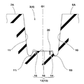
図2には、センター主溝4の断面図として、図1のA-A断面が示されている。図3には、図2の斜視図が示される。図2及び図3に示されるように、センター主溝4は、溝中心線G1と直角な横断面において、第1溝壁10と、第2溝壁11と、溝底12とを有している。なお、「溝中心線」とは、本明細書では、溝幅の中心を通る線であり、タイヤ半径方向位置については、特に限定されるものではない。
第1溝壁10は、センター陸部6のトレッド踏面6Aからタイヤ半径方向の内方にのびている。本実施形態の第1溝壁10は、トレッド踏面6Aの法線nに対し角度α1で傾斜する第1部分10Aと、第1部分10Aに滑らかに接続され第1部分10Aよりも大きな角度α2で傾斜する第2部分10Bとを含んでいる。本実施形態では第2部分10Bの溝中心線G1側の内端10tが、第1溝壁10のタイヤ半径方向の内端10iである。
第2溝壁11は、ミドル陸部7のトレッド踏面7Aからタイヤ半径方向の内方にのびている。本実施形態の第2溝壁11は、第1溝壁10と同様に、第1部分11Aと、第1部分11Aよりも大きな角度で傾斜する第2部分11Bとを含んでいる。第2部分11Bの溝中心線G1側の内端11tは、第2溝壁11のタイヤ半径方向の内端11iである。
本実施形態の第1溝壁の第2部分10B、及び、第2溝壁の第2部分11Bは、円弧状かつ溝中心線G1側に向かって前記角度が漸増している。このような両第2部分10B、11Bは、センター主溝4の剛性を大きく高める。
溝底12は、第1溝壁10の前記内端10iと第2溝壁11の前記内端11iとを継いでいる。溝底12には、タイヤ半径方向外側に凸となる突状部13を含んでいる。このような突状部13は、溝底12の剛性を高め、トレッド部2の接地時に、溝底12に生じる振動を抑制する。従って、溝底12が励起する気柱共鳴音が小さくなり、騒音性能が向上する。本実施形態の溝底12は、突状部13のみで構成されているが、その一部が突状部13であっても良い。
突状部13は、本実施形態では、第1傾斜部14と第2傾斜部15とを含んだ三角形状である。第1傾斜部14は、第1溝壁10の内端10iから溝中心線G1側に向かってタイヤ半径方向外側に傾斜している。第2傾斜部15は、第2溝壁11の内端11iから溝中心線G1側に向かってタイヤ半径方向外側に傾斜している。このような突状部13は、大きな応力が作用する溝底12の中央部分の剛性を効果的に高めつつ、溝底12の陸部6、7側において十分な溝容積を確保することができる。第1傾斜部14と第2傾斜部15とは、本実施形態では、溝中心線G1上で互いに接続されている。
突状部13は、センター主溝4の溝中心線G1と直角方向の幅W3が、センター主溝4の溝幅W1の50%~100%である。突状部13の前記幅W3がセンター主溝4の溝幅W1の50%未満の場合、溝底12の振動を効果的に抑制できない。なお、センター主溝4の深さD1を確保して摩耗末期での外観を高めるため、突状部13の幅W3が、センター主溝4の幅W1の100%を超えることはない。突状部13の幅W3は、好ましくは、センター主溝4の溝幅W1の55%~95%である。
突状部13は、第1溝壁10の内端10iと第2溝壁11の内端11iとを直線で継ぐ仮想溝底12A(仮想線で示す)からタイヤ半径方向外側にはみ出す断面積が、センター主溝4の溝断面積の3%~15%である。突状部13の断面積がセンター主溝4の断面積の3%未満の場合、突状部13の容積が小さく、溝底12の剛性を高めることができない。突状部13の断面積がセンター主溝4の断面積の15%を超える場合、センター主溝4の断面積が小さくなり、排水性能が悪化する。好ましくは、突状部13の断面積は、センター主溝4の断面積の5%~13%である。
突状部13のタイヤ半径方向の最も外側の頂部13tは、センター主溝4の溝中心線G1上に位置しているのが望ましい。これにより、最も大きな応力が作用する溝底12の溝中心線G1上の剛性が高められ、突状部13による振動抑制効果が効果的に発揮される。頂部が溝中心線上にあるとは、溝中心線を通りかつ溝を埋めて得られる仮想トレッド面に対する法線と頂部とが交差する態様である。
突状部13は、本実施形態のセンター主溝4に沿って連続している。従って、溝底12の振動抑制効果がタイヤ周方向に連続して発揮される。
本実施形態の突状部13には、サイピング20が設けられている。図4に示されるように、サイピング20は、厚さが小さい切れ込みであり、突状部13からタイヤ半径方向の内方にのびるサイプ壁20Aを有している。これにより、溝底12に生じた気柱共鳴音の加振源となるタイヤ半径方向の振動が、サイプ壁20Aで減衰される。従って、センター主溝4内の気柱共鳴がさらに抑制される。
本実施形態のサイピング20のサイプ壁20Aは、直線状にのびている。このようなサイピング20は、溝底12の剛性を高く確保する。サイプ壁20Aは、このような態様に限定されるものではなく、その面積を大きく確保して、大きな減衰効果を発揮させるため、例えば、ジグザグ状や波状のものでも良い。
サイピング20の深さDaが、サイピング20が設けられた位置での突状部13の仮想溝底12Aからのタイヤ半径方向の高さHの50%未満の場合、サイプ壁20Aの振動減衰効果が小さくなるおそれがある。サイピング20の底が仮想溝底12Aよりもタイヤ半径方向の内方にある場合、溝底12の剛性が小さくなり、溝底12に生じる振動が大きくなるおそれがある。このため、サイピング20の深さDaは、好ましくは、サイピング20が設けられた位置での突状部13の仮想溝底12Aからのタイヤ半径方向の高さHの50%~100%であり、より好ましくは60%~100%である。
サイピング20の幅W4は、好ましくは、0.6~0.8mmである。サイピング20の幅W4が0.6mm未満の場合、サイピング20を形成するためのナイフブレードの幅が小さくなり、タイヤ製造時にナイフブレードが破損して、サイピング20を形成できないおそれがある。サイピング20の幅W4が0.8mmを超える場合、溝底12の剛性が低下し、溝底12の振動が大きくなるおそれがある。
図3に示されるように、サイピング20は、センター主溝4の溝中心線G1に沿ってのびている。これにより、振動減衰効果がタイヤ周方向に連続して発揮される。本実施形態のサイピング20は、直線状にのびているが、例えば、波状やジグザグ状にのびるものでも良い。
図4に示されるように、サイピング20は、本実施形態では、突状部13に2本設けられている。これにより、サイプ壁20Aによる振動減衰効果が大きく発揮される。なお、突状部13に複数本のサイピング20が設けられる場合、サイプ壁20Aによる振動減衰効果と溝底12の剛性確保による振動抑制効果とをバランス良く発揮させるため、サイピング20の1ピッチP(図4に示す)は、1.0~3.0mmが望ましい。また、サイピング20は、溝中心線G1を挟んで等ピッチに配されるのが望ましい。
サイピング20は、突状部13に1本設けられる場合、突状部13の幅方向の中間位置に設けられるのが望ましい。これにより、サイピングの深さDaを大きく確保することができ、効果的に振動を減衰することができる。
直進走行時、タイヤ赤道C上には、最も大きな接地圧が作用する。このため、センター主溝4がタイヤ赤道C上をのびる場合、サイピング20は、タイヤ赤道C上に設けられるのが望ましい。
図5には、本発明の他の実施形態のセンター主溝4の断面図が示される。図5に示されるように、センター主溝4の溝底12は、第1溝壁10の前記内端10iと第2溝壁11の前記内端11iとを滑らかに継ぐ略半円弧状の突状部13を有する態様でも良い。このような突状部13は、溝底12の剛性をさらに高め、振動を抑制することができる。
図6には、本願発明のさらに他の実施形態のセンター主溝4の断面図が示される。図6に示されるように、この実施形態の溝底12は、第1傾斜部14と第2傾斜部15と外側部16とを含む略台形状で形成されている。このような突状部13は、溝底12の剛性を溝幅方向に沿って、ほぼ均一に高めることができる。
上記実施形態では、センター主溝4に、突状部13及びサイピング20が設けられているが、それに代えて、又はそれと共に、図1に示されるように、ショルダー主溝5の溝底にも、突状部13及びサイピング20が形成されても良い。
以上、本発明の空気入りタイヤについて詳細に説明したが、本発明は上記の具体的な実施形態に限定されることなく種々の態様に変更して実施される。
図1の基本パターンを有するサイズ235/45R18の空気入りタイヤが、表1の仕様に基づき試作され、各試供タイヤの排水性能及び騒音性能がテストされた。各試供タイヤの共通仕様やテスト方法は、以下の通りである。
トレッド接地幅TW:190mm
センター主溝の溝深さ:8.2mm
センター主溝の溝幅/トレッド接地幅:6.8%
ショルダー主溝の溝深さ:8.2mm
ショルダー主溝の溝幅/トレッド接地幅:3.7%
サイピングの幅:0.8mm
トレッド接地幅TW:190mm
センター主溝の溝深さ:8.2mm
センター主溝の溝幅/トレッド接地幅:6.8%
ショルダー主溝の溝深さ:8.2mm
ショルダー主溝の溝幅/トレッド接地幅:3.7%
サイピングの幅:0.8mm
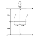
<騒音性能(実車による惰行通過騒音)>
各試供タイヤが、下記の条件で、排気量2000ccの乗用車の全輪に装着された。図7に示されるように、このテスト車両を、タイヤ単体騒音規制に係る国際基準(ECE R117)に準拠して、1名のテストドライバーが、A-B間を、エンジン停止かつギヤをニュートラルの状態で惰行走行させた。そして、この惰行走行時の最大騒音レベルが測定された。騒音測定具Sは、車両走行中心C-Cから両側に7.5±0.05m離間させかつ地上高さ1.2±0.02mの位置に取り付けられた。結果は、従来例1の騒音レベルとの差(dB(A))で評価された。数値が大きいほど良好である。
リム:8.0J×18
内圧:176kPa(平均)
荷重:4.60kN(平均)
A-B間の速度:70~90km/h
<排水性能>
上記テスト車両を、テストドライバーが、半径100mのアスファルト路面のテストコースに設けた水深10mm、長さ20mの水たまり上を、速度80km/hで進入させた。このときの前輪に作用する平均横加速度(横G)が算出された。結果は、従来例1の値を100とする指数で表示された。数値が大きいほど良好である。
テストの結果が表1に示される。
上記テスト車両を、テストドライバーが、半径100mのアスファルト路面のテストコースに設けた水深10mm、長さ20mの水たまり上を、速度80km/hで進入させた。このときの前輪に作用する平均横加速度(横G)が算出された。結果は、従来例1の値を100とする指数で表示された。数値が大きいほど良好である。
テストの結果が表1に示される。
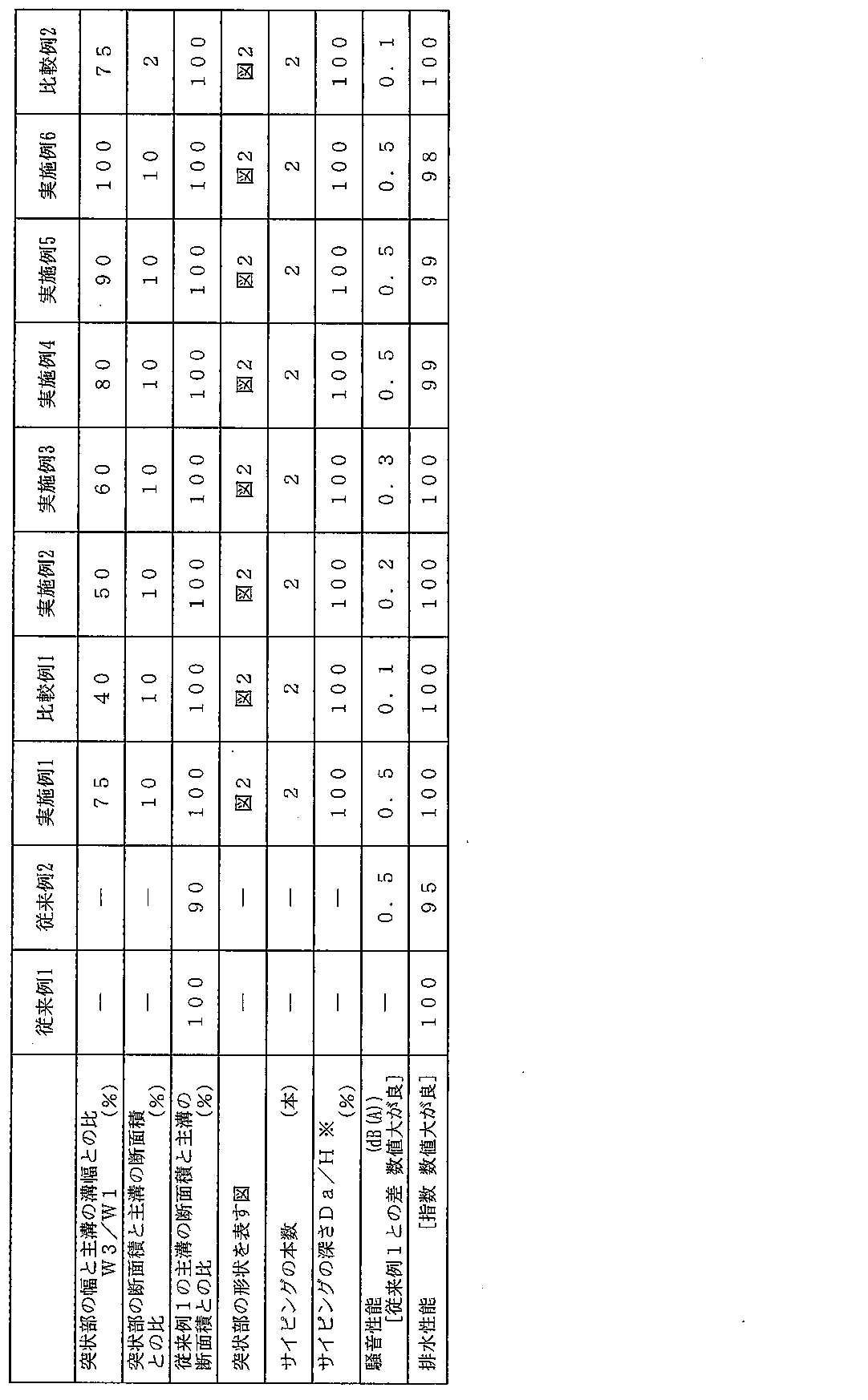

テストの結果、実施例のタイヤは、従来例及び比較例のタイヤに比べて有意に向上している。また、サイピングの幅を変化させたタイヤについてテストを行ったが、サイピングの幅が、0.6~0.8mmの範囲で結果が良かった。
2 トレッド部
3 主溝
3G 主溝の溝中心線
10 第1溝壁
10i 第1溝壁の内端
11 第2溝壁
11i 第2溝壁の内端
12 溝底
12A 仮想溝底
13 突状部
3 主溝
3G 主溝の溝中心線
10 第1溝壁
10i 第1溝壁の内端
11 第2溝壁
11i 第2溝壁の内端
12 溝底
12A 仮想溝底
13 突状部
Claims (6)
- トレッド部に、タイヤ周方向に連続してのびる少なくとも1本の主溝が設けられた空気入りタイヤであって、
前記主溝は、溝中心線と直角な横断面において、一方のトレッド踏面からタイヤ半径方向の内方にのびる第1溝壁、他方のトレッド踏面からタイヤ半径方向の内方にのびる第2溝壁、及び、前記第1溝壁のタイヤ半径方向の内端と前記第2溝壁のタイヤ半径方向の内端とを継ぎかつタイヤ半径方向外側に凸となる突状部を含む溝底を有し、
前記突状部は、前記主溝に沿って連続し、かつ、前記主溝の前記溝中心線と直角方向の幅が、前記主溝の溝幅の50%~100%であり、
前記第1溝壁の前記内端と前記第2溝壁の前記内端とを直線で継ぐ仮想溝底からタイヤ半径方向外側にはみ出す前記突状部の断面積は、前記主溝の溝断面積の3%~15%であることを特徴とする空気入りタイヤ。 - 前記突状部のタイヤ半径方向の最も外側の頂部は、前記主溝の前記溝中心線上に位置している請求項1記載の空気入りタイヤ。
- 前記主溝は、タイヤ周方向に直線状にのびている請求項1又は2記載の空気入りタイヤ。
- 前記突状部には、前記主溝の前記溝中心線に沿ってのびるサイピングが設けられる請求項1乃至3のいずれかに記載の空気入りタイヤ。
- 前記サイピングの深さは、前記サイピングを設けた位置での前記突状部の前記仮想溝底からのタイヤ半径方向の高さの50%~100%である請求項4記載の空気入りタイヤ。
- 前記サイピングは、前記突状部の前記幅方向の中間位置よりもタイヤ軸方向の内側又はタイヤ赤道上に設けられる請求項4又は5記載の空気入りタイヤ。
Priority Applications (3)
| Application Number | Priority Date | Filing Date | Title |
|---|---|---|---|
| US14/908,943 US10207545B2 (en) | 2013-08-21 | 2014-07-23 | Pneumatic tire |
| CN201480043269.6A CN105452018B (zh) | 2013-08-21 | 2014-07-23 | 充气轮胎 |
| EP14837871.4A EP3028877B1 (en) | 2013-08-21 | 2014-07-23 | Pneumatic tire |
Applications Claiming Priority (2)
| Application Number | Priority Date | Filing Date | Title |
|---|---|---|---|
| JP2013-171587 | 2013-08-21 | ||
| JP2013171587A JP5848731B2 (ja) | 2013-08-21 | 2013-08-21 | 空気入りタイヤ |
Publications (1)
| Publication Number | Publication Date |
|---|---|
| WO2015025670A1 true WO2015025670A1 (ja) | 2015-02-26 |
Family
ID=52483451
Family Applications (1)
| Application Number | Title | Priority Date | Filing Date |
|---|---|---|---|
| PCT/JP2014/069456 WO2015025670A1 (ja) | 2013-08-21 | 2014-07-23 | 空気入りタイヤ |
Country Status (5)
| Country | Link |
|---|---|
| US (1) | US10207545B2 (ja) |
| EP (1) | EP3028877B1 (ja) |
| JP (1) | JP5848731B2 (ja) |
| CN (1) | CN105452018B (ja) |
| WO (1) | WO2015025670A1 (ja) |
Cited By (1)
| Publication number | Priority date | Publication date | Assignee | Title |
|---|---|---|---|---|
| US10800212B2 (en) * | 2016-07-11 | 2020-10-13 | Sumitomo Rubber Industries, Ltd. | Pneumatic tire |
Families Citing this family (11)
| Publication number | Priority date | Publication date | Assignee | Title |
|---|---|---|---|---|
| CN106671706A (zh) * | 2016-08-31 | 2017-05-17 | 青岛双星轮胎工业有限公司 | 轮胎 |
| JP6766561B2 (ja) * | 2016-09-29 | 2020-10-14 | 住友ゴム工業株式会社 | タイヤ |
| JP2019104410A (ja) * | 2017-12-13 | 2019-06-27 | Toyo Tire株式会社 | 空気入りタイヤ |
| JP7017981B2 (ja) * | 2018-05-18 | 2022-02-09 | Toyo Tire株式会社 | 空気入りタイヤ |
| JP7196588B2 (ja) * | 2018-12-19 | 2022-12-27 | 横浜ゴム株式会社 | 空気入りタイヤ |
| JP7251166B2 (ja) * | 2019-01-25 | 2023-04-04 | 住友ゴム工業株式会社 | タイヤ |
| JP2021194927A (ja) * | 2020-06-09 | 2021-12-27 | 住友ゴム工業株式会社 | 空気入りタイヤ |
| FR3111292B1 (fr) * | 2020-06-10 | 2022-08-26 | Michelin & Cie | Bande de roulement de pneumatique pour un véhicule poids lourd avec une résistance aux agressions améliorée |
| CN111873719A (zh) * | 2020-08-12 | 2020-11-03 | 合肥工业大学 | 低噪声轮胎中主沟槽降噪结构 |
| US20220088967A1 (en) * | 2020-09-22 | 2022-03-24 | The Goodyear Tire & Rubber Company | Tire tread |
| JP2023132074A (ja) * | 2022-03-10 | 2023-09-22 | Toyo Tire株式会社 | 空気入りタイヤ |
Citations (6)
| Publication number | Priority date | Publication date | Assignee | Title |
|---|---|---|---|---|
| JPS62194908A (ja) * | 1986-02-22 | 1987-08-27 | Sumitomo Rubber Ind Ltd | 重車両用空気入りタイヤ |
| JPH09150609A (ja) * | 1995-11-28 | 1997-06-10 | Sumitomo Rubber Ind Ltd | 空気入りタイヤ |
| JPH11198610A (ja) * | 1998-01-19 | 1999-07-27 | Sumitomo Rubber Ind Ltd | 重荷重用タイヤ |
| JP2002211210A (ja) | 2001-01-12 | 2002-07-31 | Toyo Tire & Rubber Co Ltd | 空気入りタイヤ |
| JP2005119614A (ja) * | 2003-10-20 | 2005-05-12 | Sumitomo Rubber Ind Ltd | 空気入りタイヤ |
| JP2008296795A (ja) * | 2007-05-31 | 2008-12-11 | Sumitomo Rubber Ind Ltd | 空気入りタイヤ |
Family Cites Families (8)
| Publication number | Priority date | Publication date | Assignee | Title |
|---|---|---|---|---|
| JPH069922B2 (ja) * | 1983-05-12 | 1994-02-09 | 住友ゴム工業株式会社 | 良路高速走行重荷重用ラジアルタイヤ |
| JPH0271002U (ja) * | 1988-11-21 | 1990-05-30 | ||
| JPH0966708A (ja) | 1995-08-31 | 1997-03-11 | Yokohama Rubber Co Ltd:The | 空気入りタイヤ |
| JP3273742B2 (ja) * | 1997-02-14 | 2002-04-15 | 住友ゴム工業株式会社 | 空気入りタイヤ |
| JPH10250317A (ja) * | 1997-03-13 | 1998-09-22 | Bridgestone Corp | 重荷重用空気入りタイヤ |
| JP4212617B2 (ja) | 2006-10-02 | 2009-01-21 | 東洋ゴム工業株式会社 | 空気入りタイヤ |
| KR100934609B1 (ko) * | 2008-05-19 | 2009-12-31 | 한국타이어 주식회사 | 자동차용 타이어 |
| JP5632823B2 (ja) | 2011-12-26 | 2014-11-26 | 住友ゴム工業株式会社 | 重荷重用空気入りタイヤ |
-
2013
- 2013-08-21 JP JP2013171587A patent/JP5848731B2/ja not_active Expired - Fee Related
-
2014
- 2014-07-23 CN CN201480043269.6A patent/CN105452018B/zh not_active Expired - Fee Related
- 2014-07-23 EP EP14837871.4A patent/EP3028877B1/en not_active Not-in-force
- 2014-07-23 US US14/908,943 patent/US10207545B2/en active Active
- 2014-07-23 WO PCT/JP2014/069456 patent/WO2015025670A1/ja active Application Filing
Patent Citations (6)
| Publication number | Priority date | Publication date | Assignee | Title |
|---|---|---|---|---|
| JPS62194908A (ja) * | 1986-02-22 | 1987-08-27 | Sumitomo Rubber Ind Ltd | 重車両用空気入りタイヤ |
| JPH09150609A (ja) * | 1995-11-28 | 1997-06-10 | Sumitomo Rubber Ind Ltd | 空気入りタイヤ |
| JPH11198610A (ja) * | 1998-01-19 | 1999-07-27 | Sumitomo Rubber Ind Ltd | 重荷重用タイヤ |
| JP2002211210A (ja) | 2001-01-12 | 2002-07-31 | Toyo Tire & Rubber Co Ltd | 空気入りタイヤ |
| JP2005119614A (ja) * | 2003-10-20 | 2005-05-12 | Sumitomo Rubber Ind Ltd | 空気入りタイヤ |
| JP2008296795A (ja) * | 2007-05-31 | 2008-12-11 | Sumitomo Rubber Ind Ltd | 空気入りタイヤ |
Cited By (1)
| Publication number | Priority date | Publication date | Assignee | Title |
|---|---|---|---|---|
| US10800212B2 (en) * | 2016-07-11 | 2020-10-13 | Sumitomo Rubber Industries, Ltd. | Pneumatic tire |
Also Published As
| Publication number | Publication date |
|---|---|
| JP5848731B2 (ja) | 2016-01-27 |
| EP3028877A1 (en) | 2016-06-08 |
| US20160159163A1 (en) | 2016-06-09 |
| CN105452018A (zh) | 2016-03-30 |
| EP3028877A4 (en) | 2017-03-22 |
| JP2015039952A (ja) | 2015-03-02 |
| CN105452018B (zh) | 2018-04-03 |
| US10207545B2 (en) | 2019-02-19 |
| EP3028877B1 (en) | 2019-04-24 |
Similar Documents
| Publication | Publication Date | Title |
|---|---|---|
| JP5848731B2 (ja) | 空気入りタイヤ | |
| JP5503622B2 (ja) | 空気入りタイヤ | |
| JP4369734B2 (ja) | 空気入りタイヤ | |
| JP6082378B2 (ja) | 空気入りタイヤ | |
| JP5667617B2 (ja) | 空気入りタイヤ | |
| JP5802243B2 (ja) | 空気入りタイヤ | |
| JP5291739B2 (ja) | 空気入りタイヤ | |
| JP6438344B2 (ja) | 自動二輪車用空気入りタイヤ | |
| JP5973942B2 (ja) | 空気入りタイヤ | |
| KR20120116338A (ko) | 공기 타이어 | |
| US9630454B2 (en) | Pneumatic tire | |
| JP5913247B2 (ja) | 空気入りタイヤ | |
| JP5503634B2 (ja) | 空気入りタイヤ | |
| JP6450261B2 (ja) | 空気入りタイヤ | |
| JP2017136998A (ja) | タイヤ | |
| JP6496208B2 (ja) | 空気入りタイヤ | |
| JP2018176881A (ja) | タイヤ | |
| JP6383323B2 (ja) | 空気入りタイヤ | |
| JP5476497B2 (ja) | 空気入りタイヤ | |
| JP6575660B2 (ja) | 空気入りタイヤ | |
| JP6417226B2 (ja) | 空気入りタイヤ | |
| JP6013952B2 (ja) | 空気入りタイヤ | |
| JP2020100220A (ja) | タイヤ | |
| JP5782480B2 (ja) | 空気入りタイヤ | |
| JP6130760B2 (ja) | 空気入りタイヤ |
Legal Events
| Date | Code | Title | Description |
|---|---|---|---|
| WWE | Wipo information: entry into national phase |
Ref document number: 201480043269.6 Country of ref document: CN |
|
| 121 | Ep: the epo has been informed by wipo that ep was designated in this application |
Ref document number: 14837871 Country of ref document: EP Kind code of ref document: A1 |
|
| WWE | Wipo information: entry into national phase |
Ref document number: 14908943 Country of ref document: US |
|
| NENP | Non-entry into the national phase |
Ref country code: DE |
|
| WWE | Wipo information: entry into national phase |
Ref document number: 2014837871 Country of ref document: EP |