WO2015019927A1 - 光記録媒体 - Google Patents
光記録媒体 Download PDFInfo
- Publication number
- WO2015019927A1 WO2015019927A1 PCT/JP2014/070151 JP2014070151W WO2015019927A1 WO 2015019927 A1 WO2015019927 A1 WO 2015019927A1 JP 2014070151 W JP2014070151 W JP 2014070151W WO 2015019927 A1 WO2015019927 A1 WO 2015019927A1
- Authority
- WO
- WIPO (PCT)
- Prior art keywords
- layer
- recording
- optical
- recording medium
- inorganic
- Prior art date
- Legal status (The legal status is an assumption and is not a legal conclusion. Google has not performed a legal analysis and makes no representation as to the accuracy of the status listed.)
- Ceased
Links
Images



Classifications
-
- G—PHYSICS
- G11—INFORMATION STORAGE
- G11B—INFORMATION STORAGE BASED ON RELATIVE MOVEMENT BETWEEN RECORD CARRIER AND TRANSDUCER
- G11B7/00—Recording or reproducing by optical means, e.g. recording using a thermal beam of optical radiation by modifying optical properties or the physical structure, reproducing using an optical beam at lower power by sensing optical properties; Record carriers therefor
- G11B7/24—Record carriers characterised by shape, structure or physical properties, or by the selection of the material
- G11B7/241—Record carriers characterised by shape, structure or physical properties, or by the selection of the material characterised by the selection of the material
- G11B7/252—Record carriers characterised by shape, structure or physical properties, or by the selection of the material characterised by the selection of the material of layers other than recording layers
- G11B7/257—Record carriers characterised by shape, structure or physical properties, or by the selection of the material characterised by the selection of the material of layers other than recording layers of layers having properties involved in recording or reproduction, e.g. optical interference layers or sensitising layers or dielectric layers, which are protecting the recording layers
-
- G—PHYSICS
- G11—INFORMATION STORAGE
- G11B—INFORMATION STORAGE BASED ON RELATIVE MOVEMENT BETWEEN RECORD CARRIER AND TRANSDUCER
- G11B7/00—Recording or reproducing by optical means, e.g. recording using a thermal beam of optical radiation by modifying optical properties or the physical structure, reproducing using an optical beam at lower power by sensing optical properties; Record carriers therefor
- G11B7/24—Record carriers characterised by shape, structure or physical properties, or by the selection of the material
- G11B7/2403—Layers; Shape, structure or physical properties thereof
- G11B7/24067—Combinations of two or more layers with specific interrelation
-
- G—PHYSICS
- G11—INFORMATION STORAGE
- G11B—INFORMATION STORAGE BASED ON RELATIVE MOVEMENT BETWEEN RECORD CARRIER AND TRANSDUCER
- G11B7/00—Recording or reproducing by optical means, e.g. recording using a thermal beam of optical radiation by modifying optical properties or the physical structure, reproducing using an optical beam at lower power by sensing optical properties; Record carriers therefor
- G11B7/24—Record carriers characterised by shape, structure or physical properties, or by the selection of the material
- G11B7/241—Record carriers characterised by shape, structure or physical properties, or by the selection of the material characterised by the selection of the material
- G11B7/242—Record carriers characterised by shape, structure or physical properties, or by the selection of the material characterised by the selection of the material of recording layers
- G11B7/243—Record carriers characterised by shape, structure or physical properties, or by the selection of the material characterised by the selection of the material of recording layers comprising inorganic materials only, e.g. ablative layers
-
- G—PHYSICS
- G11—INFORMATION STORAGE
- G11B—INFORMATION STORAGE BASED ON RELATIVE MOVEMENT BETWEEN RECORD CARRIER AND TRANSDUCER
- G11B7/00—Recording or reproducing by optical means, e.g. recording using a thermal beam of optical radiation by modifying optical properties or the physical structure, reproducing using an optical beam at lower power by sensing optical properties; Record carriers therefor
- G11B7/24—Record carriers characterised by shape, structure or physical properties, or by the selection of the material
- G11B7/241—Record carriers characterised by shape, structure or physical properties, or by the selection of the material characterised by the selection of the material
- G11B7/242—Record carriers characterised by shape, structure or physical properties, or by the selection of the material characterised by the selection of the material of recording layers
- G11B7/243—Record carriers characterised by shape, structure or physical properties, or by the selection of the material characterised by the selection of the material of recording layers comprising inorganic materials only, e.g. ablative layers
- G11B2007/24302—Metals or metalloids
- G11B2007/24312—Metals or metalloids group 14 elements (e.g. Si, Ge, Sn)
-
- G—PHYSICS
- G11—INFORMATION STORAGE
- G11B—INFORMATION STORAGE BASED ON RELATIVE MOVEMENT BETWEEN RECORD CARRIER AND TRANSDUCER
- G11B7/00—Recording or reproducing by optical means, e.g. recording using a thermal beam of optical radiation by modifying optical properties or the physical structure, reproducing using an optical beam at lower power by sensing optical properties; Record carriers therefor
- G11B7/24—Record carriers characterised by shape, structure or physical properties, or by the selection of the material
- G11B7/241—Record carriers characterised by shape, structure or physical properties, or by the selection of the material characterised by the selection of the material
- G11B7/242—Record carriers characterised by shape, structure or physical properties, or by the selection of the material characterised by the selection of the material of recording layers
- G11B7/243—Record carriers characterised by shape, structure or physical properties, or by the selection of the material characterised by the selection of the material of recording layers comprising inorganic materials only, e.g. ablative layers
- G11B2007/24302—Metals or metalloids
- G11B2007/24314—Metals or metalloids group 15 elements (e.g. Sb, Bi)
-
- G—PHYSICS
- G11—INFORMATION STORAGE
- G11B—INFORMATION STORAGE BASED ON RELATIVE MOVEMENT BETWEEN RECORD CARRIER AND TRANSDUCER
- G11B7/00—Recording or reproducing by optical means, e.g. recording using a thermal beam of optical radiation by modifying optical properties or the physical structure, reproducing using an optical beam at lower power by sensing optical properties; Record carriers therefor
- G11B7/24—Record carriers characterised by shape, structure or physical properties, or by the selection of the material
- G11B7/241—Record carriers characterised by shape, structure or physical properties, or by the selection of the material characterised by the selection of the material
- G11B7/242—Record carriers characterised by shape, structure or physical properties, or by the selection of the material characterised by the selection of the material of recording layers
- G11B7/243—Record carriers characterised by shape, structure or physical properties, or by the selection of the material characterised by the selection of the material of recording layers comprising inorganic materials only, e.g. ablative layers
- G11B2007/24318—Non-metallic elements
- G11B2007/2432—Oxygen
-
- G—PHYSICS
- G11—INFORMATION STORAGE
- G11B—INFORMATION STORAGE BASED ON RELATIVE MOVEMENT BETWEEN RECORD CARRIER AND TRANSDUCER
- G11B7/00—Recording or reproducing by optical means, e.g. recording using a thermal beam of optical radiation by modifying optical properties or the physical structure, reproducing using an optical beam at lower power by sensing optical properties; Record carriers therefor
- G11B7/24—Record carriers characterised by shape, structure or physical properties, or by the selection of the material
- G11B7/241—Record carriers characterised by shape, structure or physical properties, or by the selection of the material characterised by the selection of the material
- G11B7/252—Record carriers characterised by shape, structure or physical properties, or by the selection of the material characterised by the selection of the material of layers other than recording layers
- G11B7/257—Record carriers characterised by shape, structure or physical properties, or by the selection of the material characterised by the selection of the material of layers other than recording layers of layers having properties involved in recording or reproduction, e.g. optical interference layers or sensitising layers or dielectric layers, which are protecting the recording layers
- G11B2007/25701—Record carriers characterised by shape, structure or physical properties, or by the selection of the material characterised by the selection of the material of layers other than recording layers of layers having properties involved in recording or reproduction, e.g. optical interference layers or sensitising layers or dielectric layers, which are protecting the recording layers consisting essentially of organic materials
-
- G—PHYSICS
- G11—INFORMATION STORAGE
- G11B—INFORMATION STORAGE BASED ON RELATIVE MOVEMENT BETWEEN RECORD CARRIER AND TRANSDUCER
- G11B7/00—Recording or reproducing by optical means, e.g. recording using a thermal beam of optical radiation by modifying optical properties or the physical structure, reproducing using an optical beam at lower power by sensing optical properties; Record carriers therefor
- G11B7/24—Record carriers characterised by shape, structure or physical properties, or by the selection of the material
- G11B7/241—Record carriers characterised by shape, structure or physical properties, or by the selection of the material characterised by the selection of the material
- G11B7/252—Record carriers characterised by shape, structure or physical properties, or by the selection of the material characterised by the selection of the material of layers other than recording layers
- G11B7/258—Record carriers characterised by shape, structure or physical properties, or by the selection of the material characterised by the selection of the material of layers other than recording layers of reflective layers
- G11B2007/2582—Record carriers characterised by shape, structure or physical properties, or by the selection of the material characterised by the selection of the material of layers other than recording layers of reflective layers based on silver
-
- G—PHYSICS
- G11—INFORMATION STORAGE
- G11B—INFORMATION STORAGE BASED ON RELATIVE MOVEMENT BETWEEN RECORD CARRIER AND TRANSDUCER
- G11B7/00—Recording or reproducing by optical means, e.g. recording using a thermal beam of optical radiation by modifying optical properties or the physical structure, reproducing using an optical beam at lower power by sensing optical properties; Record carriers therefor
- G11B7/24—Record carriers characterised by shape, structure or physical properties, or by the selection of the material
- G11B7/2403—Layers; Shape, structure or physical properties thereof
- G11B7/24035—Recording layers
- G11B7/24038—Multiple laminated recording layers
-
- G—PHYSICS
- G11—INFORMATION STORAGE
- G11B—INFORMATION STORAGE BASED ON RELATIVE MOVEMENT BETWEEN RECORD CARRIER AND TRANSDUCER
- G11B7/00—Recording or reproducing by optical means, e.g. recording using a thermal beam of optical radiation by modifying optical properties or the physical structure, reproducing using an optical beam at lower power by sensing optical properties; Record carriers therefor
- G11B7/24—Record carriers characterised by shape, structure or physical properties, or by the selection of the material
- G11B7/2403—Layers; Shape, structure or physical properties thereof
- G11B7/24047—Substrates
- G11B7/2405—Substrates being also used as track layers of pre-formatted layers
Definitions
- the present invention relates to an optical recording medium suitable for multilayering.
- the recording layer is multi-layered.
- a method is known in which tracking control during recording or reproduction of data on the recording layer is performed using a guide layer provided separately from the recording layer.
- the recording layer of the optical recording medium is made of a material that causes a large difference in reflectance between the recorded portion and the unrecorded portion due to a chemical or physical change caused by the heat of the laser beam.
- the constituent material of the recording layer an inorganic material and an organic dye material are known, and different materials are used for the write-once recording layer and the rewritable recording layer.
- Patent Document 1 describes a write-once type multilayer optical recording medium using a Bi—Ge—O-based material for a recording layer.
- Patent Document 2 describes a write-once type optical recording medium having a single layer structure in which a Bi—O-based thin film, an organic material thin film, and an Ag reflective layer are sequentially laminated on a substrate having a tracking control guide groove. Has been.
- the recording layer farthest from the incident surface of the laser beam needs to have a transmittance that allows the laser beam with sufficient power to reach the recording layer, while a recording mark can be formed on each recording layer. Sufficient heat storage and reflectivity are required.
- an object of the present invention is to provide an optical recording medium capable of improving the heat storage property of a recording layer without reducing the reflectance.
- an optical recording medium includes a guide layer, one or more inorganic recording layers, a first optical adjustment layer, a buffer layer, and a light absorption layer.
- the guide layer includes a guide track for tracking control and a reflective film made of a metal material that covers the guide track.
- the inorganic recording layer is made of a material containing at least Bi and O.
- the first optical adjustment layer is disposed between the reflective film and the inorganic recording layer and is made of a metal oxide material.
- the buffer layer is disposed between the reflective film and the first optical adjustment layer, and has a thickness larger than the depth of the guide track.
- the light absorption layer is disposed adjacent to the inorganic recording layer and has a thermal conductivity lower than that of the reflective film.
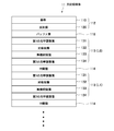
- FIG. 1 is a schematic cross-sectional view showing an optical recording medium according to an embodiment of the present invention. It is a schematic sectional drawing which shows the structure of the guide layer of the said optical recording medium. It is a schematic diagram which shows the guide track of the said guide layer. It is a schematic sectional drawing which shows the layer structure of the recording / reproducing layer of the said optical recording medium. It is a schematic sectional drawing of the optical recording medium explaining the experiment example of this invention.
- An optical recording medium includes a guide layer, one or more inorganic recording layers, a first optical adjustment layer, a buffer layer, and a light absorption layer.
- the guide layer includes a guide track for tracking control and a reflective film made of a metal material that covers the guide track.
- the inorganic recording layer is made of a material containing at least Bi and O.
- the first optical adjustment layer is disposed between the reflective film and the inorganic recording layer and is made of a metal oxide material.
- the buffer layer is disposed between the reflective film and the first optical adjustment layer, and has a thickness larger than the depth of the guide track.
- the light absorption layer is disposed adjacent to the inorganic recording layer and has a thermal conductivity lower than that of the reflective film. *
- the optical recording medium is configured as a guide layer separation type optical recording medium in which a reflective film of a guide layer and an inorganic recording layer are laminated via a buffer layer. And since the inorganic recording layer is separated from the reflective film having high heat dissipation by the buffer layer, and the light absorption layer is made of a material having a lower thermal conductivity than the reflective film, the inorganic recording layer It is possible to ensure the heat storage necessary for forming the recording mark. In addition, since no tracking control groove is formed in the recording layer, the heat storage effect of the inorganic recording layer can be increased.
- the first optical adjustment layer made of a metal oxide material is disposed between the reflective layer and the inorganic recording layer, the recording / reproducing light, particularly after the formation of the recording mark, is sufficient. The reflectance can be ensured.
- both the heat storage necessary for forming the recording mark and the reflectance characteristic necessary for detecting the recording / reproducing light are combined. Can be suppressed.
- the light absorption layer may be composed of an inorganic material or an organic pigment material.
- the light absorption layer is made of an organic material containing an organic dye.
- a material containing at least Bi (bismuth) and O (oxygen) is used for the inorganic recording layer.
- the positional relationship between the inorganic recording layer and the light absorption layer is not particularly limited, and the light absorption layer may be disposed between the first optical adjustment layer and the inorganic recording layer, or the first optical adjustment layer and An inorganic recording layer may be disposed between the light absorption layer. In any configuration, an optical recording medium having sufficient reflectance characteristics with respect to recording / reproducing light can be obtained.
- the thermal conductivity of the light absorption layer can be set to, for example, 0.05 [W / m ⁇ K] or more and 1.2 [W / m ⁇ K] or less.
- the thermal conductivity of the light absorption layer is less than 0.05 [W / m ⁇ K]
- the recording sensitivity is inferior and it is difficult to form a recording mark.
- the thermal conductivity of the light absorption layer exceeds 1.2 [W / m ⁇ K]
- it is difficult to form a recording mark without ensuring sufficient heat storage by heat radiation.
- the optical recording medium may further include a second optical adjustment layer made of a metal oxide material.
- the second optical adjustment layer is disposed on the opposite side of the inorganic recording layer from the reflective film side.
- the inorganic recording layer may include a plurality of inorganic recording layers. Thereby, a multilayer optical recording medium having a good recording sensitivity can be constituted.
- FIG. 1 is a schematic sectional view showing an optical recording medium according to an embodiment of the present invention. *
- the optical recording medium 11 of the present embodiment is configured by a guide layer separation type multilayer optical disc having a guide layer 112 and a plurality of recording / reproducing layers 113.
- the illustrated optical recording medium 11 has four recording / reproducing layers 113, but is not limited thereto, and may have one to three layers or five or more recording / reproducing layers.
- the optical recording medium 11 has a disk shape, and a center hole is formed in the central portion. *
- a light-transmitting buffer layer 116 and an intermediate layer 114 are interposed between the guide layer 112 and the nearest recording / reproducing layer 113 and between the adjacent recording / reproducing layers 113.
- These layers are layered. These layers are a protective layer (cover layer) 115, a recording / reproducing layer 113 (L3), and an intermediate layer 114 from the side on which recording / reproducing light R1 and guide light R2 from an optical pickup in a recording / reproducing apparatus (not shown) are incident.
- the recording / reproducing layer 113 (L2), the intermediate layer 114, the recording / reproducing layer 113 (L1), the intermediate layer 114, the recording / reproducing layer 113 (L0), the buffer layer 116, and the guide layer 112 are laminated in this order.
- the recording / reproducing light R1 and the guide light R2 are controlled so as to be focused on the target recording / reproducing layer 113 and the guide layer 112 via the objective lens 60.
- Laser beams having different wavelengths are used for the recording / reproducing light R1 and the guide light R2.
- blue laser light having a wavelength of 405 nm is used for the recording / reproducing light R1
- wavelength 650 nm is used for the guide light R2. Red laser light is used.
- FIG. 2 is a schematic cross-sectional view showing the configuration of the guide layer 112
- FIG. 3 is a schematic diagram showing the guide track of the guide layer 112. *
- the guide layer 112 covers the uneven portion 111 in accordance with the uneven shape of the uneven portion 111 and the plastic base material 110 such as a disk-shaped polycarbonate having a spiral uneven portion 111 on one surface. It has a laminated structure with the reflective film 120.
- the substrate 110 is typically molded using a molding die such as a stamper, and has an outer diameter of 120 mm and a thickness of 1.1 mm.
- the reflective film 120 is formed of a sputtered film of a metal material having a high reflectance with respect to red laser light, such as silver (Ag) or an alloy thereof.
- the thickness of the reflective film 120 is not particularly limited, and is, for example, 20 nm to 100 nm, and in this embodiment, 80 nm. *
- a guide track 121 for tracking control is formed on the surface of the guide layer 112 facing the recording / reproducing layer 113 as shown in FIGS.
- the guide track 121 has a land / groove structure formed in a spiral shape.
- the land is formed between the grooves, and the groove is formed between the lands.
- a track closer to the laser light source (optical pickup) is referred to as “groove” or “on-groove portion”, and a track farther from the laser light source is referred to as “land”.
- it is referred to as an “in-groove part”. *
- the guide track 121 includes a land-based guide track (in-groove portion 121L) and a groove-based guide track (on-groove portion 121G), and means for switching between the land track and the groove track every round is used.
- a so-called “double spiral track” may be configured.
- the in-groove portion 121L and the on-groove portion 121G are continuously formed in a spiral shape from the inner peripheral side to the outer peripheral side of the optical recording medium 11, but are not limited thereto.
- the in-groove portion 121L and the on-groove portion 121G may be continuously formed in a spiral shape so that they are alternately switched at a predetermined period (for example, every circumference) from the inner circumference side to the outer circumference side of the optical recording medium 11. .
- the in-groove portion 121L and the on-groove portion 121G may be a concentric arrangement of a plurality of annular grooves.
- the in-groove portion 121L is surrounded by a pair of side walls 121s that form a boundary with the on-groove portion 121G.
- the side wall 121s is typically formed with a tapered surface, but may be formed with a surface perpendicular to the surface of the substrate 110.
- the taper angle of the side wall 121s is not particularly limited, and is appropriately set according to the draft angle of the stamper mold, the uneven height of the uneven portion 111, the thickness of the reflective film 120, and the like. *
- the in-groove portion 121L and the on-groove portion 121G are formed with a track pitch (0.64 ⁇ m) corresponding to red laser light used for recording / reproduction of a DVD (Digital Versatile Disk), for example.
- the average pitch between the land and the groove is 0.32 ⁇ m, which corresponds to the track pitch of the guide track 121.
- the laser beam of the red laser beam is referred to as “guide light”.
- the push-pull method (PP: Push-Pull)
- the differential push-pull method (DPP: Differential-Push-Pull)
- Tracking control is performed by a three-beam method or the like.
- FIG. 4 is a schematic sectional view showing the layer structure of the recording / reproducing layer. *
- the recording / reproducing layers 113 (L0 to L3) of the respective layers have the same layer structure and are laminated with the intermediate layer 114 interposed therebetween.
- the recording / reproducing layer 113 (L0) closest to the guide layer 112 is formed on the buffer layer 116 formed with a thickness larger than the depth of the guide track 121 covered with the reflective film 120. Therefore, the recording / reproducing layer 113 and the intermediate layer 114 formed on the buffer layer 116 are sequentially laminated on a flat plane without a groove (guide track).
- Each recording / reproducing layer 113 has a laminated structure of a first optical adjustment layer 131, a light absorption layer 132, an inorganic recording layer 133, and a second optical adjustment layer 134.
- the inorganic recording layer 133 records information at a track pitch (0.32 ⁇ m) corresponding to blue laser light having a wavelength of 380 to 450 nm (in this example, 405 nm) used for recording and reproduction of a Blu-ray Disc (registered trademark), for example. Is a layer.
- this blue laser light is referred to as “recording / reproducing light” or “recording light”.
- the inorganic recording layer 133 is made of a material containing at least Bi (bismuth) and O (oxygen). By using such a material, it is possible to form a write-once type inorganic recording layer that can write information but cannot rewrite information.
- Bi-MO is a material containing at least Bi and O (where M is Mg (magnesium), Ca (calcium), Y (yttrium), Dy (dysprosium), Ce (cerium), Tb (terbium). , Ti (titanium), Zr (zirconium), V (vanadium), Nb (niobium), Ta (tantalum), Mo (molybdenum), W (tungsten), Mn (manganese), Fe (iron), Zn (zinc) Al (aluminum), In (indium), Si (silicon), Ge (germanium), Sn (tin), Sb (antimony), Li (lithium), Na (sodium), K (potassium), Sr (strontium) , Ba (barium), Sc (scandium), La (lanthanum), Nd (neodymium), Sm (samarium), Gd (gadori) Um), Ho (holmium), Cr (chromium), Co (cobalt), Ni (nic
- the inorganic recording layer 133 is typically formed on the light absorption layer 132 by a sputtering method.
- the thickness of the inorganic recording layer 133 is not particularly limited, and is, for example, 10 nm to 70 nm, and is appropriately set according to the layer position and the number of layers of the recording / reproducing layer 113. *
- the light absorption layer 132 is for compensating for heat absorption efficiency that is insufficient with the inorganic recording layer 133 alone, and is disposed adjacent to the inorganic recording layer 133.
- the light absorbing layer 132 may be disposed adjacent to the recording / reproducing light incident side of the inorganic recording layer 133 or may be disposed adjacent to the opposite side thereof.
- the light absorption layer 132 is disposed between the inorganic recording layer 133 and the first optical adjustment layer 131, but between the inorganic recording layer 133 and the second optical adjustment layer 134. It may be arranged. *
- the light absorption layer 132 is made of an inorganic material or an organic material, and is made of an organic dye material in this embodiment.
- the light absorption layer 132 is thermally decomposed by absorption of the recording / reproducing light R1, and heat generated by the heat decomposition is propagated to the inorganic recording layer 133, thereby improving the heat storage property of the inorganic recording layer 133.
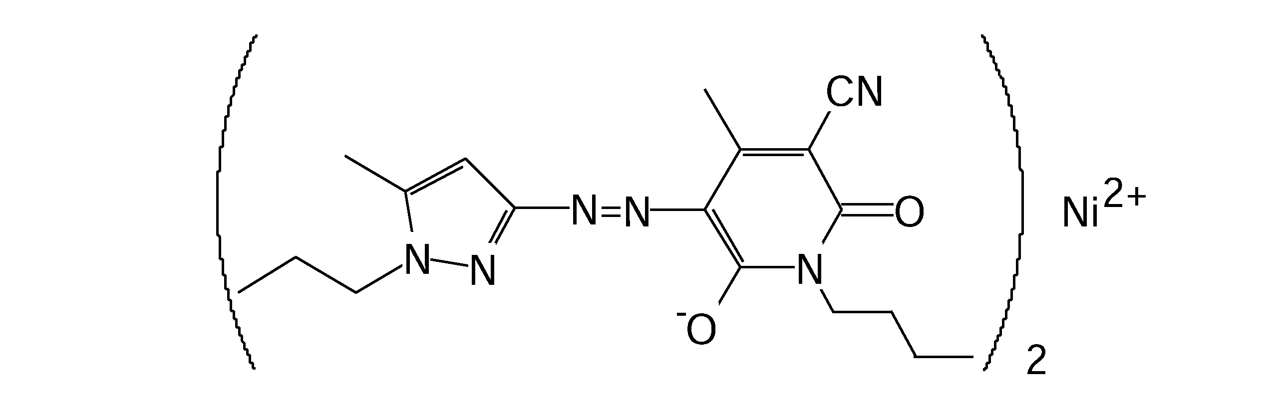
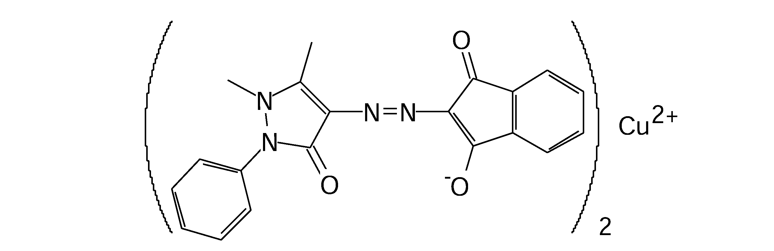
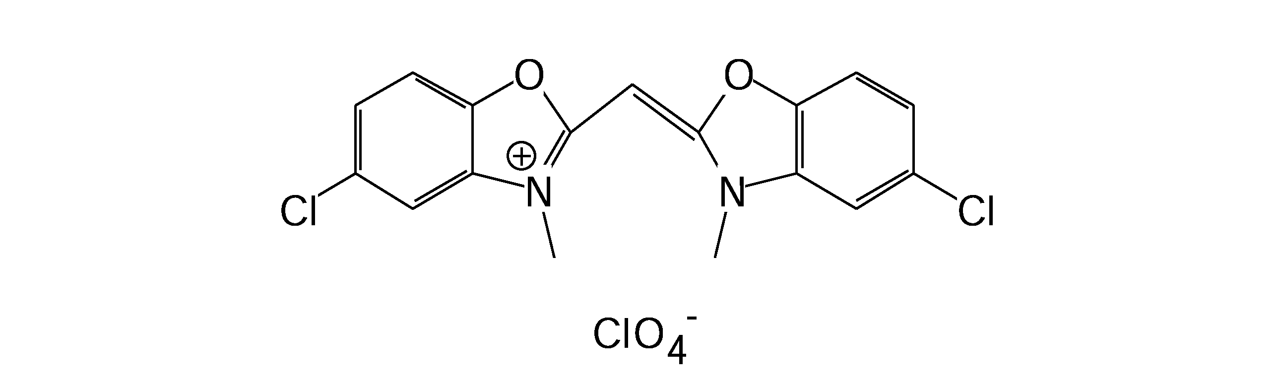
- the organic dye material constituting the light absorption layer 132 is not particularly limited, and an appropriate material such as a cyanine dye or an azo dye is used.
- an appropriate material such as a cyanine dye or an azo dye is used.
- a material having a high transmittance for the guide light R2 and an appropriate transmittance and absorption for the recording / reproducing light R1 is used.
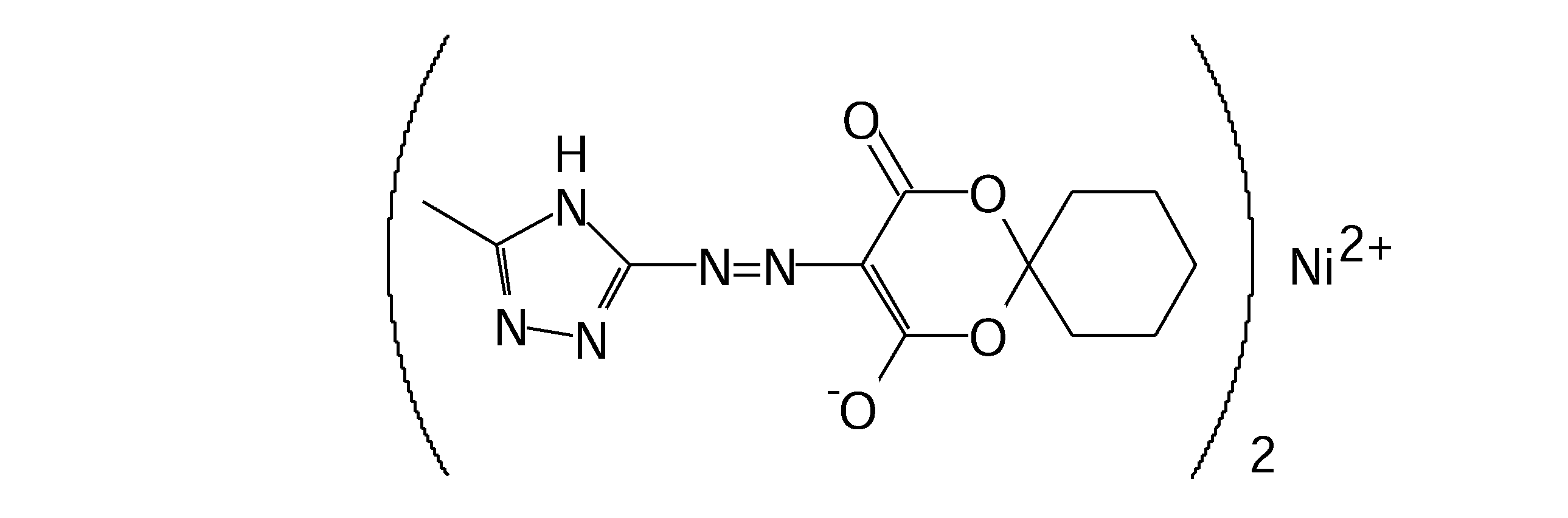
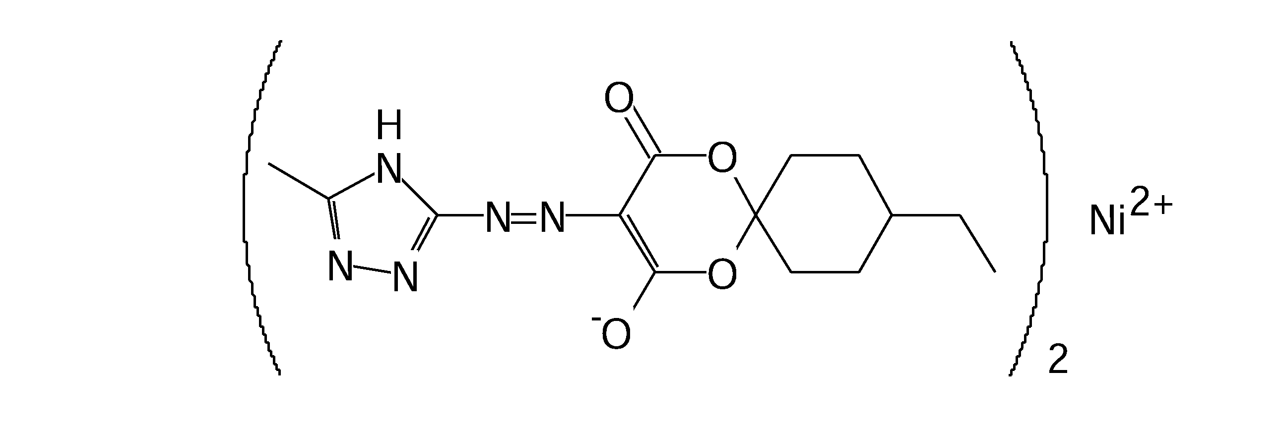
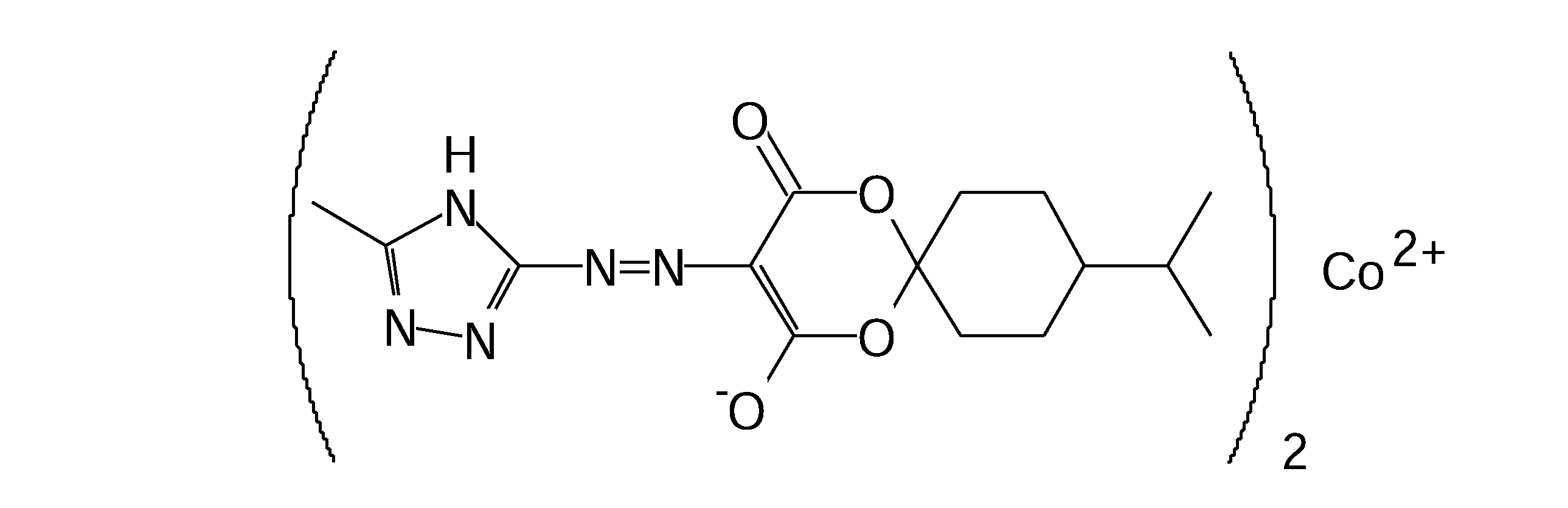
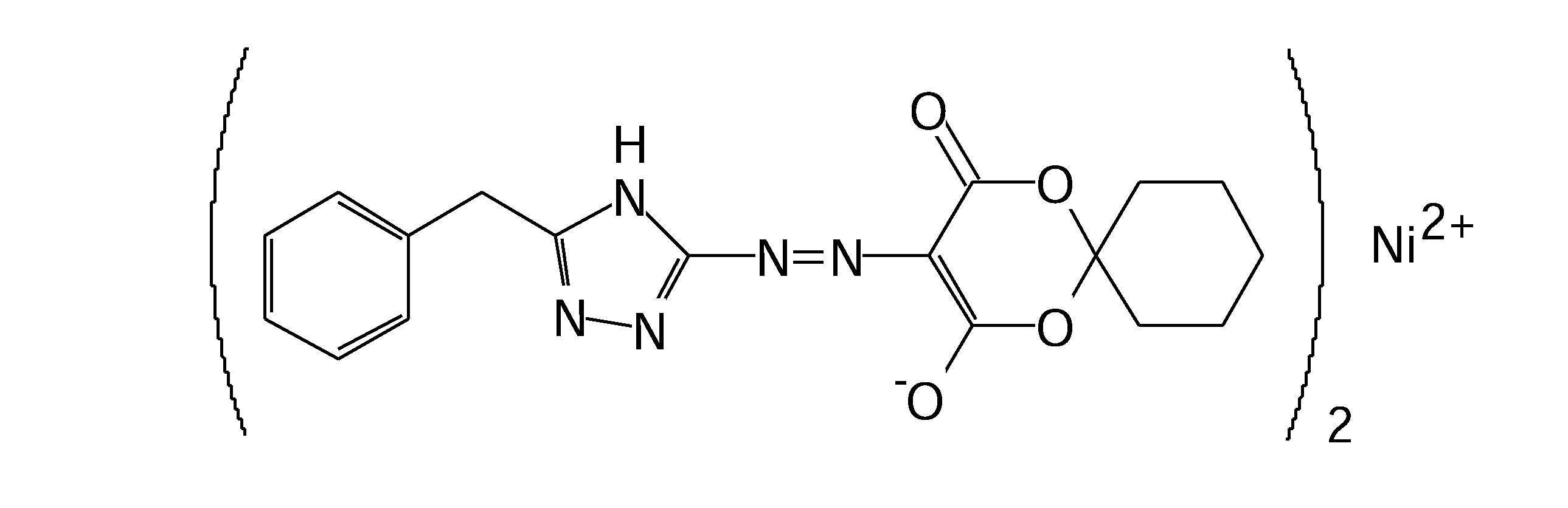
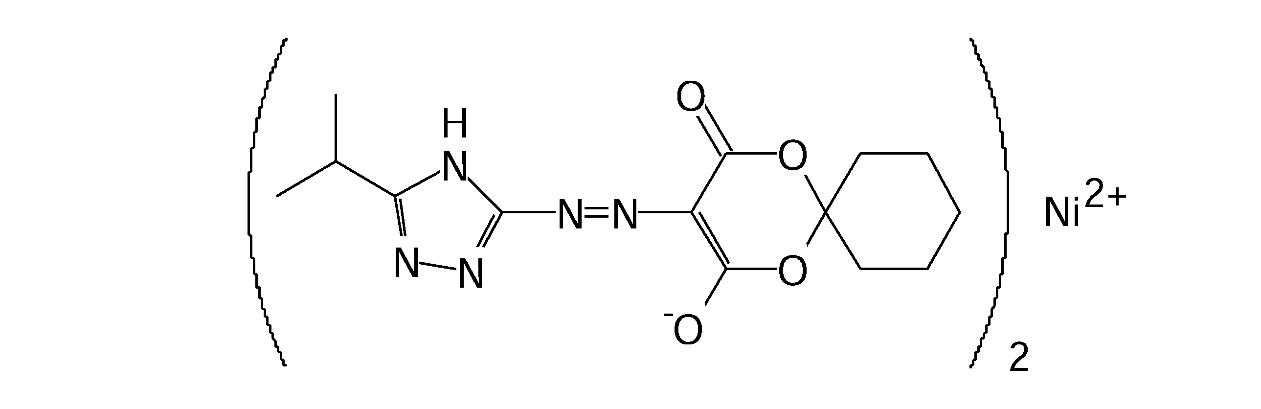
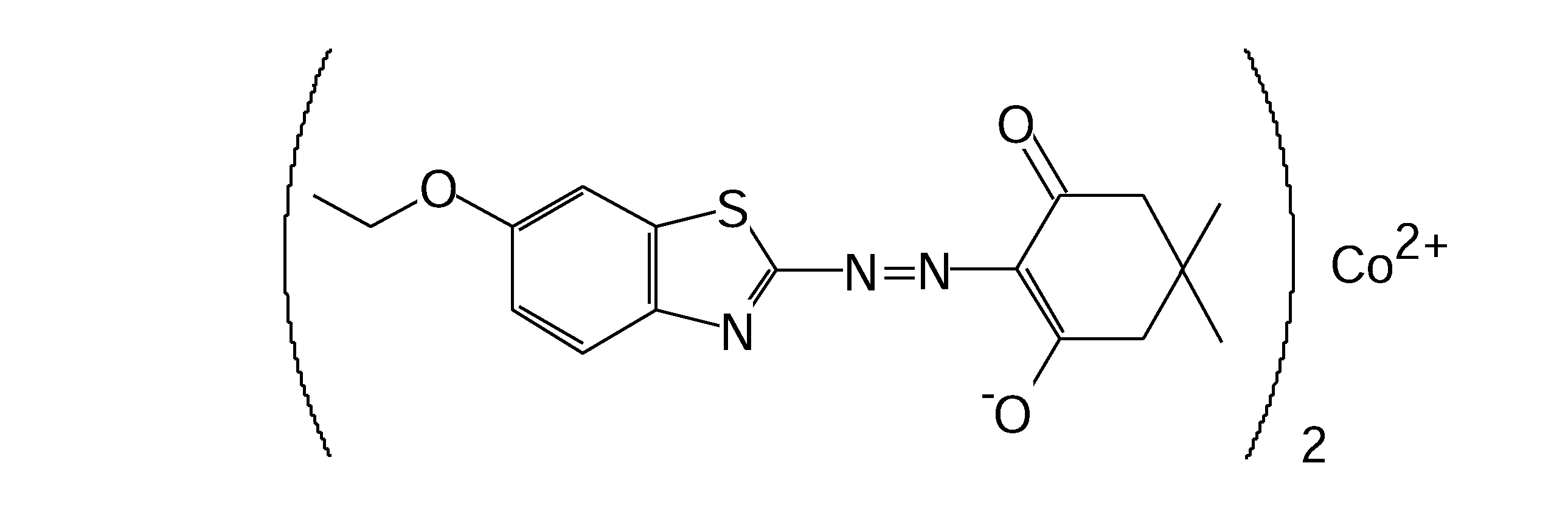
- any one of the dyes represented by the following structural formulas [Chemical Formula 1] to [Chemical Formula 21] is used. *
- the light absorption layer 132 is formed on the first optical adjustment layer 131 by using a dye solution obtained by dissolving the dye in a predetermined solvent using an appropriate coating method such as a spin coat method.
- the thickness of the light absorption layer 132 is not particularly limited, and is appropriately set according to the target reflectance, the layer position of the recording / reproducing layer 113, the number of layers, and the like.
- the light absorption layer 132 has a thermal conductivity lower than that of the reflective film 120.
- the magnitude of the thermal conductivity of the light absorption layer 132 can be, for example, 0.05 [W / m ⁇ K] or more and 1.2 [W / m ⁇ K] or less.
- the thermal conductivity of the light absorption layer 132 is less than 0.05 [W / m ⁇ K]
- the recording sensitivity is inferior and it is difficult to appropriately form a recording mark on the inorganic recording layer 133.
- the thermal conductivity of the light absorbing layer 132 exceeds 1.2 [W / m ⁇ K]
- the thermal conductivity of the light absorption layer 132 is 0.05 [W / m ⁇ K] or more and 1.2 [W / m ⁇ K] or less, the recording mark can be stably formed.
- the first optical adjustment layer 131 is disposed between the reflective film 120 and the inorganic recording layer 133 for the purpose of ensuring the reflectance necessary for reproducing information (record marks) recorded on the inorganic recording layer 133.
- the first optical adjustment layer 131 is made of a metal oxide material, for example, a SnO 2 -based, TiO 2 -based, SiO 2 -based, or ZnO-SnO 2 -based glass material.
- the magnitude of the reflectance adjusted by the first optical adjustment layer 131 is not particularly limited.
- the reflectance of the recording / reproducing light R1 before the formation of the recording mark is less than 1%, and the recording / reproduction after the recording mark is formed.
- the reflectance of the light R1 is set to be 0.8% to 0.1%.
- the first optical adjustment layer 131 also has a function as a boundary layer that partitions between the light absorption layer 132 and the buffer layer 116 or the intermediate layer 114. Thereby, the light absorption layer 132 and the buffer layer 116 or the intermediate layer 114 can be appropriately separated.
- the first optical adjustment layer 131 is typically formed on the buffer layer 116 or the intermediate layer 114 by a sputtering method.
- the thickness of the first optical adjustment layer 131 is not particularly limited, and is, for example, 20 nm to 100 nm, and is appropriately set according to the target reflectance, the layer position of the recording / reproducing layer 113 or the number of layers thereof.
- the second optical adjustment layer 134 is for assisting the function of adjusting the optical characteristics (reflectance, etc.) of the recording / reproducing layer 113 by the first optical adjustment layer 131, and the laser beam incident side of the inorganic recording layer 133. That is, it is disposed on the side opposite to the reflective film 120 side.
- the second optical adjustment layer 134 is made of a metal oxide material. In the present embodiment, the second optical adjustment layer 134 is made of the same material as the first optical adjustment layer 131. *
- the second optical adjustment layer 134 is typically formed on the inorganic recording layer 133 by a sputtering method.
- the thickness of the second optical adjustment layer 134 is not particularly limited, and is, for example, 20 nm to 100 nm.
- the thickness of the first optical adjustment layer 131, the target reflectance, the layer position of the recording / reproducing layer 113, or the number of layers thereof It is set appropriately according to *
- the intermediate layer 114, the protective layer 115, and the buffer layer 116 are made of a resin material that is transparent to the guide light and the recording / reproducing light, for example, an ultraviolet curable resin material.
- the intermediate layer 114, the protective layer 115, and the buffer layer 116 are typically formed by a coating method such as a spin coating method.
- the thicknesses of the intermediate layer 114, the protective layer 115, and the buffer layer 116 are not particularly limited, and are appropriately set according to optical characteristics such as a desired transmittance. *
- the optical recording medium 11 is rotationally driven at an appropriate speed in a CLV system or CAV system in a recording / reproducing apparatus (not shown), and is irradiated with the guide light R2 on the guide track 121 of the guide layer 112, and a predetermined recording / reproducing layer.
- 113 is irradiated with recording / reproducing light (or recording light) R1.
- the recording / reproducing layer 113 records information in areas corresponding to the in-groove portion 121L and the on-groove portion 121G of the guide track 121.
- the inorganic recording layer 133 forms a recording mark by causing a required phase transformation in the irradiation region of the recording / reproducing light R1. A certain difference or more in the reflectance difference is ensured between the recording mark formation site and the non-formation site, and information can be read.
- the optical recording medium 11 of the present embodiment is configured as a guide layer separation type optical recording medium in which the reflective film 120 of the guide layer 112 and the inorganic recording layer 133 are laminated via the buffer layer 116.
- the inorganic recording layer 133 is disposed by being separated from the reflective film 120 with high heat dissipation by the buffer layer 116, and the light absorbing layer 132 is made of a material having a lower thermal conductivity than the reflective film 120. It is possible to ensure the heat storage necessary for forming the recording mark on the recording layer 133.
- the optical recording medium 11 of this embodiment has a large refractive index change because the first optical adjustment layer 131 made of a metal oxide material is disposed between the reflective film 120 and the inorganic recording layer 133. Thus, it is possible to ensure a sufficient reflectance of the recording / reproducing light R1 particularly after the recording mark is formed.
- FIG. 5 is a schematic cross-sectional view showing the configuration of the optical recording medium 10 according to Experimental Example 1.
- the optical recording medium 10 is a guide layer separation type recording medium having a single recording / reproducing layer 113, and the manufacturing procedure thereof is as follows. *
- a stamper having grooves for forming guide tracks with a track pitch of 0.64 ⁇ m was mounted on a molding die, and a disk-shaped polycarbonate substrate (base material) 110 having an outer diameter of 120 mm and a thickness of 1.1 mm was produced by injection molding. .
- the annular area from the position of the radius of 23.5 mm to the radius of 58.0 mm is used as the guide area where the guide track is formed.
- a reflective film 120 made of an Ag-0.2 wt% In alloy was sputtered to a thickness of 80 nm on the surface of the guide track.
- a UV curable resin was applied on the reflective film by a spin coat method so as to have a film thickness of 200 ⁇ m, and cured to form a buffer layer 116. Then, a first optical adjustment layer 131 having a thickness of 30 nm was formed on the buffer layer 116 by sputtering a ZnO—SnO 2 glass material.
- a dye solution is prepared by dissolving the dye represented by the structural formula of [Chemical Formula 1] in a TFP (tetrafluoropropanol) solvent, and the dye solution is spin-coated on the first optical adjustment layer 131.
- TFP tetrafluoropropanol
- the OD value refers to the absorbance when the dye film is formed directly without forming the reflective film on the substrate with the absorbance of the substrate alone as the baseline (OD value is zero).
- a Ge—Bi—O-based inorganic material layer was formed on the light absorption layer 132 by sputtering to form an inorganic recording layer 133 having a thickness of 35 nm. Bi 2 O 3 and GeO 2 were used as targets. Then, a second optical adjustment layer 134 having a thickness of 54 nm was formed on the inorganic recording layer 133 by sputtering a ZnO—SnO 2 glass material. Finally, a UV curable resin was applied on the second optical adjustment layer 134 by a spin coating method so as to have a film thickness of 100 ⁇ m and cured to form a protective layer (cover layer) 115.
- the recording / reproduction characteristics of the optical recording medium 10 manufactured as described above were evaluated using an optical disc drive unit “ODU-1000” manufactured by Pulse Tech Industrial Co., Ltd. Specifically, the optical recording medium is rotated at a linear velocity of 7.68 m / s, and a laser beam (guide light) having a wavelength of 650 nm and an output of 0.3 mW is focused on the in-groove portion to execute tracking tracking control. Then, a recording mark was formed by condensing laser light (recording light) having a wavelength of 405 nm on the region of the inorganic recording layer corresponding to the in-groove portion. Then, the power (output) of the recording light that minimizes iMLSE when reproduced with laser light (reproducing light) having a wavelength of 405 nm and an output of 1.1 mW, and the reflectance at that time were evaluated.
- ODU-1000 optical disc drive unit
- iMLSE Maximum likelihood sequence ⁇ ⁇ ⁇ error
- PRML Partial Response Maximum Likelihood
- the recording power at which iMLSE was minimized was 21.5 mW, and the reflectance was 0.91%.
- Example 2 An optical recording medium was prepared under the same conditions as in Experimental Example 1, except that the organic dye material constituting the light absorbing layer was a dye represented by the structural formula of [Chemical Formula 2]. The recording / reproduction characteristics were evaluated. As a result of the measurement, the recording power at which iMLSE was minimized was 21.0 mW, and the reflectance was 0.88%. *
- Example 3 An optical recording medium was prepared under the same conditions as Experimental Example 1, except that the dye represented by the structural formula of [Chemical Formula 3] was used as the organic dye material constituting the light absorption layer. The recording / reproduction characteristics were evaluated. As a result of the measurement, the recording power at which iMLSE was minimized was 20.5 mW, and the reflectance was 0.87%. *
- Example 4 An optical recording medium was prepared under the same conditions as in Experimental Example 1 except that the organic dye material constituting the light absorbing layer was a dye represented by the structural formula of [Chemical Formula 4]. The recording / reproduction characteristics were evaluated. As a result of the measurement, the recording power at which iMLSE was minimized was 22.0 mW, and the reflectance was 0.92%. *
- Example 5 An optical recording medium was prepared under the same conditions as Experimental Example 1 except that the organic dye material constituting the light absorbing layer was a dye represented by the structural formula of [Chemical Formula 5]. The recording / reproduction characteristics were evaluated. As a result of the measurement, the recording power at which iMLSE was minimized was 22.0 mW, and the reflectance was 0.93%. *
- Example 6 An optical recording medium was prepared under the same conditions as in Experimental Example 1, except that the organic dye material constituting the light absorbing layer was a dye represented by the structural formula of [Chemical Formula 6]. The recording / reproduction characteristics were evaluated. As a result of the measurement, the recording power at which iMLSE was minimized was 21.5 mW, and the reflectance was 0.91%. *
- Example 7 An optical recording medium was prepared under the same conditions as Experimental Example 1, except that the organic dye material constituting the light absorption layer was a dye represented by the structural formula of [Chemical Formula 7]. The recording / reproduction characteristics were evaluated. As a result of measurement, iMLSE was 21.5 mW and the reflectance was 0.91%.
- Example 8 An optical recording medium was prepared under the same conditions as Experimental Example 1, except that the organic dye material constituting the light absorbing layer was a dye represented by the structural formula of [Chemical Formula 8]. The recording / reproduction characteristics were evaluated. As a result of the measurement, the recording power at which iMLSE was minimized was 20.0 mW, and the reflectance was 0.84%. *
- Example 9 An optical recording medium was prepared under the same conditions as Experimental Example 1, except that the dye represented by the structural formula of [Chemical Formula 9] was used as the organic dye material constituting the light absorption layer. The recording / reproduction characteristics were evaluated. As a result of the measurement, the recording power at which iMLSE was minimized was 22.2 mW, and the reflectance was 0.96%. *
- Example 10 An optical recording medium was prepared under the same conditions as Experimental Example 1, except that the organic dye material constituting the light absorbing layer was a dye represented by the structural formula of [Chemical Formula 10]. The recording / reproduction characteristics were evaluated. As a result of the measurement, the recording power at which iMLSE was minimized was 21.0 mW, and the reflectance was 0.88%. *
- Example 11 An optical recording medium was prepared under the same conditions as in Experimental Example 1 except that the organic dye material constituting the light absorbing layer was a dye represented by the structural formula of [Chemical Formula 11]. The recording / reproduction characteristics were evaluated. As a result of the measurement, the recording power at which iMLSE was minimized was 21.0 mW, and the reflectance was 0.89%. *
- Example 12 An optical recording medium was prepared under the same conditions as in Experimental example 1 except that the organic dye material constituting the light absorbing layer was a dye represented by the structural formula of [Chemical formula 12]. The recording / reproduction characteristics were evaluated. As a result of the measurement, the recording power at which iMLSE was minimized was 22.0 mW, and the reflectance was 0.93%. *
- Example 13 An optical recording medium was prepared under the same conditions as in Experimental Example 1 except that the organic dye material constituting the light absorbing layer was a dye represented by the structural formula of [Chemical Formula 13]. The recording / reproduction characteristics were evaluated. As a result of the measurement, the recording power at which iMLSE was minimized was 21.5 mW, and the reflectance was 0.91%. *
- Example 14 An optical recording medium was manufactured under the same conditions as Experimental Example 1, except that the dye represented by the structural formula of [Chemical Formula 14] was used as the organic dye material constituting the light absorption layer. The recording / reproduction characteristics were evaluated. As a result of the measurement, the recording power at which iMLSE was minimized was 19.5 mW, and the reflectance was 0.82%. *
- Example 15 An optical recording medium was prepared under the same conditions as in Experimental Example 1 except that the organic dye material constituting the light absorbing layer was a dye represented by the structural formula of [Chemical Formula 15]. The recording / reproduction characteristics were evaluated. As a result of the measurement, the recording power at which iMLSE was minimized was 22.0 mW, and the reflectance was 0.98%. *
- Example 16 An optical recording medium was manufactured under the same conditions as Experimental Example 1, except that the dye represented by the structural formula of [Chemical Formula 16] was used as the organic dye material constituting the light absorption layer. The recording / reproduction characteristics were evaluated. As a result of the measurement, the recording power at which iMLSE was minimized was 21.0 mW, and the reflectance was 0.88%. *
- Example 17 An optical recording medium was prepared under the same conditions as in Experimental Example 1, except that the organic dye material constituting the light absorbing layer was a dye represented by the structural formula of [Chemical Formula 17]. The recording / reproduction characteristics were evaluated. As a result of the measurement, the recording power at which iMLSE was minimized was 21.5 mW, and the reflectance was 0.91%. *
- Example 18 An optical recording medium was prepared under the same conditions as in Experimental Example 1, except that the organic dye material constituting the light absorbing layer was a dye represented by the structural formula of [Chemical Formula 18]. The recording / reproduction characteristics were evaluated. As a result of the measurement, the recording power at which iMLSE was minimized was 22.0 mW, and the reflectance was 0.92%. *
- Example 19 An optical recording medium was prepared under the same conditions as in Experimental Example 1, except that the organic dye material constituting the light absorbing layer was a dye represented by the structural formula of [Chemical Formula 19]. The recording / reproduction characteristics were evaluated. As a result of the measurement, the recording power at which iMLSE was minimized was 20.0 mW, and the reflectance was 0.94%. *
- Example 20 An optical recording medium was prepared under the same conditions as in Experimental example 1 except that the dye represented by the structural formula of [Chemical formula 20] was used as the organic dye material constituting the light absorption layer. The recording / reproduction characteristics were evaluated. As a result of the measurement, the recording power at which iMLSE was minimized was 22.0 mW, and the reflectance was 0.92%. *
- Example 21 An optical recording medium was prepared under the same conditions as in Experimental Example 1, except that the organic dye material constituting the light absorbing layer was a dye represented by the structural formula of [Chemical Formula 21]. The recording / reproduction characteristics were evaluated. As a result of the measurement, the recording power at which iMLSE was minimized was 19.5 mW, and the reflectance was 0.91%. *
- Example 22 An optical recording medium was manufactured under the same conditions as in Experimental Example 1 except that the light absorption layer was formed of a sputtered film of iron oxide (Fe 3 O 4 ) having a thickness of 3 nm. evaluated. As a result of the measurement, the recording power at which iMLSE was minimized was 26.0 mW, and the reflectance was 0.91%.
- the optical recording media according to Experimental Examples 1 to 21 in which the light absorption layer is made of an organic dye material and the Experimental Example 22 in which the light absorption layer is made of an inorganic material (Fe 3 O 4 ) When compared with such an optical recording medium, it was confirmed that the reflectance was in the range of 0.8 to 1.0%. By setting the reflectance to less than 1%, the recording mark can be formed stably.
- the iMLSE minimum recording power in Experimental Examples 1 to 21 was smaller than the iMLSE minimum recording power in Experimental Example 22. That is, when the light absorption layer is made of an organic dye material, it is possible to form a recording mark with lower power than when the light absorption layer is made of Fe 3 O 4 . From this, it was confirmed that the optical recording medium in which the light absorption layer is composed of an organic dye material is highly sensitive to recording light (high recording sensitivity).
- the inventors focused on the fact that the difference in recording sensitivity between the experimental examples 1 to 21 and the experimental example 22 is the heat storage property of the light absorption layer, and compared these thermal conductivities.
- the thermal conductivity of the dye film and the inorganic film (Fe 3 O 4 ) used in Experimental Examples 1, 2, 20, 21, and 22 was measured.
- the thermal conductivity was measured by a periodic heating method.
- the measurement sample may be one that has been scraped off from the optical recording medium, or one that is formed from raw materials for measurement.
- the thermal conductivities of the samples according to Experimental Examples 1, 2, 20, 21, and 22 are 0.1 [W / m ⁇ K], 0.05 [W / m ⁇ K], 0. They were 2 [W / m ⁇ K], 1.2 [W / m ⁇ K], and 2.5 [W / m ⁇ K] (Table 1). *
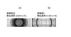
- FIG. 6 is a simulation result showing the heat distribution when the recording layer is heated under a predetermined recording condition.
- (A) shows the medium structure according to Experimental Example 22, and (B) shows the medium structure according to Experimental Example 1.
- the recording power was 10 mW, and the spot diameter of the Gaussian beam measured at the 1 / e 2 intensity point was 400 nm.
- FIG. 6B shows the sample of Experimental Example 1 (FIG. 6B) was about 180 ° C. higher than the sample of Experimental Example 22 (FIG. 6A).
- the thermal conductivity of the light absorption layer is preferably 0.05 [W / m ⁇ K] or more and 1.2 [W / m ⁇ K] or less. If it is less than 0.05 [W / m ⁇ K], it is difficult to form the recording mark appropriately because the heat storage property becomes too high and the recording mark becomes enlarged. On the other hand, if it exceeds 1.2 [W / m ⁇ K], sufficient heat storage property cannot be ensured by heat radiation, which may cause a decrease in recording sensitivity. By setting the thermal conductivity of the light absorption layer to 0.05 [W / m ⁇ K] or more and 1.2 [W / m ⁇ K] or less, the recording mark can be stably formed. *
- the inventors of the present invention have a heat storage property according to the presence or absence of a guide track groove (unevenness) in the recording layer, the presence or absence of a metal reflective film adjacent to the light absorption layer, and the thermal conductivity of the light absorption layer. Therefore, the maximum temperature reached by the light absorption layer when the same laser energy was irradiated was calculated. The results are shown in Table 2. For the calculation of the temperature, the thermal diffusion equation represented by the following [Equation 1] was used. *
- C (x) represents specific heat
- ⁇ (x) represents density
- T (x, t) represents temperature
- K (x) represents thermal conductivity
- the optical recording medium having the single recording / reproducing layer 113 has been described as an example.
- the same effect can be obtained for the optical recording medium having the multilayer recording / reproducing layer 113.
- An optical recording medium can also be configured.
- the light absorption layer 132 is disposed between the first optical adjustment layer 131 and the inorganic recording layer 133.
- the present invention is not limited to this, and the first optical adjustment layer 131 and the light absorption layer 132 are provided.
- An inorganic recording layer 133 may be disposed between the two. Even in this case, a sufficient reflectance with respect to the recording / reproducing light can be secured.
- the light absorption layer 132 was comprised with the organic pigment
- the thermal conductivity is preferably 0.05 [W / m ⁇ K] or more and 1.2 [W / m ⁇ K] or less.
Landscapes
- Chemical & Material Sciences (AREA)
- Inorganic Chemistry (AREA)
- Optical Record Carriers And Manufacture Thereof (AREA)
Abstract
【課題】反射率を低下させることなく記録層の蓄熱性を向上させることができる光記録媒体を提供する。【解決手段】本発明の一実施形態に係る光記録媒体11は、ガイド層112と、1以上の無機記録層133と、第1の光学調整層134と、バッファ層116と、光吸収層132とを具備する。ガイド層112は、トラッキング制御用のガイドトラックと、ガイドトラックを被覆する金属材料で構成された反射膜120とを有する。第1の光学調整層131は、反射膜120と無機記録層133との間に配置され、金属酸化物材料で構成される。バッファ層116は、反射膜120と第1の光学調整層131との間に配置され、上記ガイドトラックの深さよりも大きい厚みを有する。光吸収層132は、無機記録層133に隣接して配置され、反射膜120の熱伝導率よりも低い熱伝導率を有する。
Description
本発明は、多層化に適した光記録媒体に関する。
DVD(Digital Versatile Disk)、ブルーレイディスク(登録商標)などの光ディスクの大容量化を目的として、記録層を多層化することが行われる。記録層の多層化に伴い、記録層へのデータの記録または再生時のトラッキング制御を、記録層とは別に設けられたガイド層を用いて行う方式が知られている。
一方、光記録媒体の記録層は、レーザ光の熱による化学的又は物理的な変化で記録部分と未記録部分とで反射率に大きな差が生じる材料が用いられる。記録層の構成材料としては無機系材料と有機色素系材料が知られており、さらに追記型記録層と書換え型記録層とで異なる材料が用いられている。
例えば下記特許文献1には、記録層にBi-Ge-O系材料を用いた追記型の多層光記録媒体が記載されている。また下記特許文献2には、トラッキング制御用の案内溝を有する基板上にBi-O系薄膜と、有機材料薄膜と、Ag反射層とを順に積層した単層構造の追記型光記録媒体が記載されている。
多層光記録媒体においては、各記録層への記録感度の向上が要求される。例えば、レーザ光の入射面から最も遠い奥側の記録層にも十分なパワーのレーザ光が到達し得る透過率が必要とされる一方で、各記録層には記録マークを形成し得るのに十分な蓄熱性と反射率が要求される。
しかしながら上記特許文献1に記載の構造では、Bi-Ge-Oだけでは十分な熱吸収率が得られず、記録感度の向上を図ることができない。また特許文献2に記載の構造では、有機材料薄膜にAg反射層が隣接しているため熱拡散しやすく、記録層の蓄熱性が低下しやすい。その一方でAg反射層を排除すると、十分な反射率が得られず、再生特性が低下するという問題がある。このような問題は、記録層の層数が多くなるほど顕著となる。
以上のような事情に鑑み、本発明の目的は、反射率を低下させることなく記録層の蓄熱性を向上させることができる光記録媒体を提供することにある。
上記目的を達成するため、本発明の一形態に係る光記録媒体は、ガイド層と、1以上の無機記録層と、第1の光学調整層と、バッファ層と、光吸収層とを具備する。 上記ガイド層は、トラッキング制御用のガイドトラックと、上記ガイドトラックを被覆する金属材料で構成された反射膜とを有する。 上記無機記録層は、Bi及びOを少なくとも含む材料で構成される。 上記第1の光学調整層は、上記反射膜と上記無機記録層との間に配置され、金属酸化物材料で構成される。 上記バッファ層は、上記反射膜と上記第1の光学調整層との間に配置され、上記ガイドトラックの深さよりも大きい厚みを有する。 上記光吸収層は、上記無機記録層に隣接して配置され、上記反射膜の熱伝導率よりも低い熱伝導率を有する。
本発明の一実施形態に係る光記録媒体は、ガイド層と、1以上の無機記録層と、第1の光学調整層と、バッファ層と、光吸収層とを具備する。 上記ガイド層は、トラッキング制御用のガイドトラックと、上記ガイドトラックを被覆する金属材料で構成された反射膜とを有する。 上記無機記録層は、Bi及びOを少なくとも含む材料で構成される。 上記第1の光学調整層は、上記反射膜と上記無機記録層との間に配置され、金属酸化物材料で構成される。 上記バッファ層は、上記反射膜と上記第1の光学調整層との間に配置され、上記ガイドトラックの深さよりも大きい厚みを有する。 上記光吸収層は、上記無機記録層に隣接して配置され、上記反射膜の熱伝導率よりも低い熱伝導率を有する。
上記光記録媒体は、ガイド層の反射膜と無機記録層とがバッファ層を介して積層された、ガイド層分離型の光記録媒体として構成される。そして無機記録層は、バッファ層によって放熱性の高い上記反射膜から隔てて配置され、かつ、光吸収層に上記反射膜よりも熱伝導率の小さい材料が用いられているため、無機記録層への記録マークの形成に必要な蓄熱性を確保することができる。しかも、記録層にトラッキング制御用の溝が形成されていないため、無機記録層の蓄熱効果を増大させることができる。さらに上記光記録媒体は、金属酸化物材料で構成された第1の光学調整層が反射層と無機記録層との間に配置されているため、特に記録マーク形成後における記録再生光の十分な反射率を確保することができる。
したがって上記光記録媒体によれば、記録マークの形成に必要な蓄熱性と記録再生光の検出に必要な反射率特性とを兼ね備えるため、多層化したときの記録感度の低下や記録再生特性の低下を抑制することができる。
上記光吸収層は、無機材料で構成されてもよいし、有機色素材料で構成されてもよい。典型的には、上記光吸収層は、有機色素を含む有機材料で構成される。これにより、所望の熱伝導率を有する光吸収層を容易に構成することができる。
上記無機記録層には、Bi(ビスマス)及びO(酸素)を少なくとも含む材料が用いられる。
無機記録層と光吸収層との位置的関係は特に限定されず、第1の光学調整層と無機記録層との間に光吸収層が配置されてもよいし、第1の光学調整層と光吸収層との間に無機記録層が配置されてもよい。いずれの構成においても、記録再生光に対して十分な反射率特性を有する光記録媒体を得ることができる。
上記光吸収層の熱伝導率は、例えば0.05[W/m・K]以上1.2[W/m・K]以下とすることができる。光吸収層の熱伝導率が0.05[W/m・K]未満であると、記録感度が劣ってしまい記録マークを形成することが困難となる。また、光吸収層の熱伝導率が1.2[W/m・K]を超えると、放熱により十分な蓄熱性を確保できずに記録マークを形成することが困難となる。光吸収層の熱伝導率を0.05[W/m・K]以上1.2[W/m・K]以下とすることで、記録マークを安定に形成することが可能となる。
上記光記録媒体は、金属酸化物材料で構成された第2の光学調整層をさらに具備してもよい。上記第2の光学調整層は、上記無機記録層の上記反射膜側とは反対側に配置される。第2の光学調整層を設けることで、第1の光学調整層の光学特性(例えば反射率特性)を補うことができる。
上記無機記録層は、複数の無機記録層を含んでもよい。 これにより良好な記録感度を有する多層光記録媒体を構成することができる。
以下、図面を参照しながら、本発明の実施形態を説明する。
図1は、本発明の一実施形態に係る光記録媒体を示す概略断面図である。
[光記録媒体の構成] 本実施形態の光記録媒体11は、ガイド層112と複数の記録再生層113とを有する、ガイド層分離型の多層光ディスクで構成される。図示する光記録媒体11は、4層の記録再生層113を有するが、これに限られず、1層~3層あるいは5層以上の記録再生層を有してもよい。光記録媒体11は、円盤状をなし、中央部分にはセンターホールが形成されている。
光記録媒体11において、ガイド層112とこれに最も近い記録再生層113との間、及び、隣り合う記録再生層113の間には、光透過性を有するバッファ層116及び中間層114がそれぞれ介層されている。これらの層は、図示しない記録再生装置内の光ピックアップからの記録再生光R1およびガイド光R2が入射される側から、保護層(カバー層)115、記録再生層113(L3)、中間層114、記録再生層113(L2)、中間層114、記録再生層113(L1)、中間層114、記録再生層113(L0)、バッファ層116、ガイド層112の順に積層される。
記録再生光R1及びガイド光R2は、対物レンズ60を介して目的とする記録再生層113及びガイド層112に焦点を結ぶように制御される。記録再生光R1及びガイド光R2には相互に異なる波長のレーザ光が用いられ、典型的には、記録再生光R1には波長405nmの青色レーザ光が用いられ、ガイド光R2には波長650nmの赤色レーザ光が用いられる。
(ガイド層) 図2はガイド層112の構成を示す概略断面図であり、図3はガイド層112のガイドトラックを示す模式図である。
図2に示すようにガイド層112は、一方の面に渦巻き状の凹凸部111を有する円盤形状のポリカーボネート等のプラスチック基材110と、凹凸部111の凹凸形状にならって凹凸部111を被覆する反射膜120との積層構造を有する。
基材110は、典型的にはスタンパ等の成形金型を用いて成形され、外径は120mm、厚さは1.1mmで形成される。反射膜120は、例えば銀(Ag)やその合金等のように赤色レーザ光に対して反射率の高い金属材料のスパッタ膜で形成される。反射膜120の厚みは特に限定されず、例えば20nm~100nmであり、本実施形態では80nmである。
ガイド層112において記録再生層113に対向する側の面には、図2及び図3に示すようにトラッキング制御用のガイドトラック121が形成される。ガイドトラック121は、渦巻き状に形成されたランド・グルーブ構造を有する。ランドはグルーブ間に形成され、グルーブはランド間に形成される。以下の説明では、ガイドトラック121において、レーザ光源(光ピックアップ)に近い方のトラックを「グルーブ」あるいは「オングルーブ(On-Groove)部」と称し、レーザ光源から遠い方のトラックを「ランド」あるいは「イングルーブ(In-Groove)部」と称する。
ガイドトラック121は、ランドによるガイドトラック(イングルーブ部121L)とグルーブによるガイドトラック(オングルーブ部121G)とからなり、一周毎にランドトラックとグルーブトラックを切り替える手段が用いられる。いわゆる「ダブルスパイラルトラック」を構成してもよい。本実施形態では、イングルーブ部121Lおよびオングルーブ部121Gは光記録媒体11の内周側から外周側にかけてそれぞれ渦巻き状に連続的に形成されているが、これに限定されない。例えば、イングルーブ部121Lおよびオングルーブ部121Gは、光記録媒体11の内周側から外周側にかけて所定周期で(例えば周ごとに)交互に入れ替わるように渦巻き状に連続的に形成されてもよい。また例えばイングルーブ部121Lおよびオングルーブ部121Gは、複数の円環状のグルーブを同心状に配列したものであってもよい。
イングルーブ部121Lは、オングルーブ部121Gとの境界を形成する一対の側壁121sに囲まれている。側壁121sは、典型的にはテーパ面で形成されるが、基材110の表面に垂直な面で形成されてもよい。側壁121sのテーパ角は特に限定されず、スタンパ金型の抜き勾配や凹凸部111の凹凸高さ、反射膜120の厚さ等に応じて適宜設定される。
ガイドトラック121には、側壁面のウォブリングあるいはピット列などによって物理アドレス情報が形成されてい
る。イングルーブ部121Lおよびオングルーブ部121Gは、例えばDVD(Digital Versatile Disk)の記録再生に用いられる赤色レーザ光に対応するトラックピッチ(0.64μm)で形成される。ランドとグルーブ間のピッチの平均は0.32μmであり、これはガイドトラック121のトラックピッチに相当する。以後、赤色レーザ光のレーザ光を「ガイド光」と呼ぶ。
る。イングルーブ部121Lおよびオングルーブ部121Gは、例えばDVD(Digital Versatile Disk)の記録再生に用いられる赤色レーザ光に対応するトラックピッチ(0.64μm)で形成される。ランドとグルーブ間のピッチの平均は0.32μmであり、これはガイドトラック121のトラックピッチに相当する。以後、赤色レーザ光のレーザ光を「ガイド光」と呼ぶ。
光記録媒体11を駆動する記録再生装置では、ガイドトラック121のランドとグルーブのそれぞれにおいて、例えば、プッシュプル法(PP:Push-Pull)、差動プッシュプル法(DPP:Differential Push-Pull)、3ビーム法などによるトラッキング制御が行われる。ガイドトラック121のランドとグルーブのそれぞれにおいてトラッキング制御が行われることで、記録再生層113に対する情報の記録は0.32μmのトラックピッチで行うことが可能である。
(記録再生層) 図4は、記録再生層の層構造を示す概略断面図である。
各層の記録再生層113(L0~L3)はそれぞれ同一の層構造を有し、中間層114を挟んで相互に積層されている。ガイド層112に最も近い記録再生層113(L0)は、反射膜120で被覆されたガイドトラック121の深さよりも大きな厚みで形成されたバッファ層116の上に成膜される。したがってバッファ層116上に成膜される記録再生層113及び中間層114は、溝(ガイドトラック)のない平坦な平面上に順次積層される。
各々の記録再生層113は、第1の光学調整層131と、光吸収層132と、無機記録層133と、第2の光学調整層134との積層構造を有する。
無機記録層133は、例えばブルーレイディスク(登録商標)の記録再生に用いられる波長380~450nm(本例では405nm)の青色レーザ光に対応するトラックピッチ(0.32μm)で情報の記録が行われる層である。以後、この青色レーザ光を「記録再生光」または「記録光」と呼ぶ。
本実施形態において無機記録層133は、Bi(ビスマス)及びO(酸素)を少なくとも含む材料で構成される。このような材料を用いることにより、情報の追記は可能であるが書換えができない追記型無機記録層を構成することができる。
Bi及びOを少なくとも含む材料としては、Bi-M-O(ただし、Mは、Mg(マグネシウム)、Ca(カルシウム)、Y(イットリウム)、Dy(ジスプロシウム)、Ce(セリウム)、Tb(テルビウム)、Ti(チタン)、Zr(ジルコニウム)、V(バナジウム)、Nb(ニオブ)、Ta(タンタル)、Mo(モリブデン)、W(タングステン)、Mn(マンガン)、Fe(鉄)、Zn(亜鉛)、Al(アルミニウム)、In(インジウム)、Si(ケイ素)、Ge(ゲルマニウム)、Sn(錫)、Sb(アンチモン)、Li(リチウム)、Na(ナトリウム)、K(カリウム)、Sr(ストロンチウム)、Ba(バリウム)、Sc(スカンジウム)、La(ランタン)、Nd(ネオジウム)、Sm(サマリウム)、Gd(ガドリニウム)、Ho(ホルミウム)、Cr(クロム)、Co(コバルト)、Ni(ニッケル)、Cu(銅)、Ga(ガリウム)、Pb(鉛)の中から選択される少なくとも一種の元素)を主成分とする材料が挙げられる。本実施形態では、無機記録層133は、Bi-Ge-O系無機材料で構成される。
無機記録層133は、典型的には、スパッタリング法で光吸収層132の上に成膜される。無機記録層133の厚みは特に限定されず、例えば10nm~70nmであり、記録再生層113の層位置や層数等に応じて適宜設定される。
光吸収層132は、無機記録層133だけでは不足する熱吸収効率を補うためのものであり、無機記録層133に隣接して配置される。光吸収層132は、無機記録層133の記録再生光の入射側に隣接して配置されてもよいし、それとは反対側に隣接して配置されてもよい。図4に示す例では、光吸収層132は、無機記録層133と第1の光学調整層131との間に配置されるが、無機記録層133と第2の光学調整層134との間に配置されてもよい。
光吸収層132は、無機材料あるいは有機材料で構成され、本実施形態では有機色素材料で構成される。光吸収層132は、記録再生光R1の吸収により熱分解し、その熱分解に伴って発生する熱を無機記録層133へ伝播することで、無機記録層133の蓄熱性を向上させる。
光吸収層132を構成する有機色素材料は特に限定されず、シアニン系色素やアゾ系色素などの適宜の材料が用いられる。光吸収層132に用いられる有機色素材料には、ガイド光R2に対しては透過率が高く、記録再生光R1に対しては適度の透過率及び吸収率を有する材料が用いられる。本実施形態では、下記[化1]~[化21]の構造式で表される色素のうち何れか一種の色素が用いられる。








光吸収層132は、例えば、上記色素を所定の溶媒に溶かした色素溶液をスピンコート法等の適宜の塗布法を用いて第1の光学調整層131の上に成膜される。光吸収層132の厚みは特に限定されず、目的とする反射率や記録再生層113の層位置、層数等に応じて適宜設定される。
光吸収層132は、反射膜120の熱伝導率よりも低い熱伝導率を有する。光吸収層132の熱伝導率の大きさは、例えば0.05[W/m・K]以上1.2[W/m・K]以下とすることができる。光吸収層132に有機色素材料を用いることで、所望の熱伝導率を有する光吸収層を容易に構成することができる。
光吸収層132の熱伝導率が0.05[W/m・K]未満であると、記録感度が劣ってしまい無機記録層133に記録マークを適切に形成することが困難となる。また、光吸収層132の熱伝導率が1.2[W/m・K]を超えると、放熱により十分な蓄熱性を確保できずに無機記録層133に記録マークを形成することが困難となる。光吸収層132の熱伝導率を0.05[W/m・K]以上1.2[W/m・K]以下とすることで、記録マークを安定に形成することが可能となる。
第1の光学調整層131は、無機記録層133に記録された情報(記録マーク)の再生に必要な反射率を確保する目的で、反射膜120と無機記録層133との間に配置される。第1の光学調整層131は、金属酸化物材料で構成され、例えば、SnO2系、TiO2系、SiO2系、ZnO-SnO2系のガラス材料で構成される。第1の光学調整層131によって調整される反射率の大きさは特に限定されず、例えば、記録マークの形成前における記録再生光R1の反射率が1%弱、記録マークの形成後における記録再生光R1の反射率が0.8%~0.1%となるように設定される。
第1の光学調整層131は、光吸収層132とバッファ層116あるいは中間層114との間を仕切る境界層としての機能をも有する。これにより光吸収層132とバッファ層116あるいは中間層114とを適切に分離することが可能となる。
第1の光学調整層131は、典型的には、スパッタリング法でバッファ層116あるいは中間層114の上に成膜される。第1の光学調整層131の厚みは特に限定されず、例えば20nm~100nmであり、目的とする反射率や記録再生層113の層位置あるいはその層数等に応じて適宜設定される。
第2の光学調整層134は、第1の光学調整層131による記録再生層113の光学特性(反射率等)の調整機能を補助するためのものであり、無機記録層133のレーザ光入射側、すなわち反射膜120側とは反対側に配置される。第2の光学調整層134は、金属酸化物材料で構成され、本実施形態では、第1の光学調整層131と同一の材料で構成される。
第2の光学調整層134は、典型的には、スパッタリング法で無機記録層133の上に成膜される。第2の光学調整層134の厚みは特に限定されず、例えば20nm~100nmであり、第1の光学調整層131の厚みや目的とする反射率、記録再生層113の層位置あるいはその層数等に応じて適宜設定される。
(その他) 中間層114、保護層115及びバッファ層116は、ガイド光及び記録再生光に対して透明な樹脂材料、例えば紫外線硬化型の樹脂材料で構成される。中間層114、保護層115及びバッファ層116は、典型的にはスピンコート法等の塗布法によって成膜される。中間層114、保護層115及びバッファ層116の厚みは特に限定されず、目的とする透過率等の光学特性に応じて適宜設定される。
[光記録媒体の作用] 次に、以上のように構成される本実施形態の光記録媒体11の作用を説明する。
光記録媒体11は、図示しない記録再生装置において、CLV方式またはCAV方式において適切な速度で回転駆動され、ガイド層112のガイドトラック121へのガイド光R2の照射を受けつつ、所定の記録再生層113に記録再生光(あるいは記録光)R1が照射される。これにより記録再生層113は、ガイドトラック121のイングルーブ部121L及びオングルーブ部121Gに対応する領域に情報が記録される。
記録再生層113において、無機記録層133は、記録再生光R1の照射領域が所要の相変態が起きることで記録マークを形成する。記録マークの形成部位と非形成部位との間に一定以上の反射率差が確保されて情報の読取りが可能となる。
本実施形態の光記録媒体11においては、ガイド層112の反射膜120と無機記録層133とがバッファ層116を介して積層された、ガイド層分離型の光記録媒体として構成される。そして無機記録層133は、バッファ層116によって放熱性の高い反射膜120から隔てて配置され、かつ、光吸収層132に反射膜120よりも熱伝導率の小さい材料が用いられているため、無機記録層133への記録マークの形成に必要な蓄熱性を確保することができる。
さらに、無機記録層133にトラッキング制御用の溝が形成されていないため、無機記録層133の蓄熱効果を増大させることができる。さらに本実施形態の光記録媒体11は、金属酸化物材料で構成された第1の光学調整層131が反射膜120と無機記録層133との間に配置されているため、屈折率変化が大きくなり、これにより特に記録マーク形成後における記録再生光R1の十分な反射率を確保することが可能となる。
以下、本発明者らが行った実験例について説明する。なお勿論、本発明は以下の実験例に限定されない。
(実験例1) 図5は、実験例1に係る光記録媒体10の構成を示す概略断面図である。光記録媒体10は単一の記録再生層113を有するガイド層分離型記録媒体であり、その作製手順は以下のとおりである。
トラックピッチ0.64μmのガイドトラック形成用の溝を有するスタンパを成形金型に装着し、外径120mm、厚さ1.1mmの円盤状のポリカーボネート製基板(基材)110を射出成形により作製した。本例では、基板の半径23.5mmの位置から半径58.0mmまでの環状領域を上記ガイドトラックが形成されるガイド領域とした。このガイドトラックの表面に、Ag-0.2wt%In合金からなる反射膜120を80nmの厚さでスパッタ成膜した。次に、反射膜上にUV硬化樹脂を膜厚200μmになるようにスピンコート法にて塗布し、硬化させて、バッファ層116を形成した。そしてバッファ層116上に、ZnO-SnO2系のガラス材料をスパッタ成膜することで、厚さ30nmの第1の光学調整層131を形成した。
続いて、上記[化1]の構造式で表される色素をTFP(テトラフルオロプロパノール)溶剤に溶かした色素溶液を作製し、その色素溶液を第1の光学調整層131の上にスピンコート法で塗布して、光吸収層132としての色素膜を形成した。色素膜厚は、吸収最大波長(λmax=444nm)での光学密度(OD値)が0.055となるように設定した。なおOD値は、基板のみの吸光度をベースライン(OD値がゼロ)として、基板上に反射膜を形成せずに直接、色素膜を形成したときの吸光度をいう。
次に、光吸収層132の上に、Ge-Bi-O系無機材料層をスパッタ成膜することで、厚さ35nmの無機記録層133を形成した。ターゲットには、Bi2O3とGeO2を用いた。そして無機記録層133上に、ZnO-SnO2系のガラス材料をスパッタ成膜することで、厚さ54nmの第2の光学調整層134を形成した。最後に、第2の光学調整層134上にUV硬化樹脂を膜厚100μmになるようにスピンコート法にて塗布し、硬化させて、保護層(カバー層)115を形成した。
続いて、以上のようにして作製された光記録媒体10の記録再生特性をパルステック工業(株)製の光ディスクドライブユニット「ODU-1000」を用いて評価した。具体的には、光記録媒体を線速度7.68m/sで回転させ、波長650nm、出力0.3mWのレーザ光(ガイド光)をイングルーブ部に集光してトラッキング追従制御を実行しながら、当該イングルーブ部に対応する無機記録層の領域に波長405nmのレーザ光(記録光)を集光して記録マークを形成した。そして、波長405nm、出力1.1mWのレーザ光(再生光)で再生したときのiMLSEが最小となる記録光のパワー(出力)とそのときの反射率を評価した。
なお、iMLSE(Maximum likelihood sequence error)は、PRML(Partial Response Maximum Likelihood)によるビット検出方式を採用する再生システムで用いられるエラーレート相関の評価値である。
測定の結果、iMLSEが最小となる記録パワーは21.5mW、反射率は0.91%であった。
(実験例2) 光吸収層を構成する有機色素材料に上記[化2]の構造式で表される色素を用いた以外は、実験例1と同一の条件で光記録媒体を作製し、その記録再生特性を評価した。測定の結果、iMLSEが最小となる記録パワーは21.0mW、反射率は0.88%であった。
(実験例3) 光吸収層を構成する有機色素材料に上記[化3]の構造式で表される色素を用いた以外は、実験例1と同一の条件で光記録媒体を作製し、その記録再生特性を評価した。測定の結果、iMLSEが最小となる記録パワーは20.5mW、反射率は0.87%であった。
(実験例4) 光吸収層を構成する有機色素材料に上記[化4]の構造式で表される色素を用いた以外は、実験例1と同一の条件で光記録媒体を作製し、その記録再生特性を評価した。測定の結果、iMLSEが最小となる記録パワーは22.0mW、反射率は0.92%であった。
(実験例5) 光吸収層を構成する有機色素材料に上記[化5]の構造式で表される色素を用いた以外は、実験例1と同一の条件で光記録媒体を作製し、その記録再生特性を評価した。測定の結果、iMLSEが最小となる記録パワーは22.0mW、反射率は0.93%であった。
(実験例6) 光吸収層を構成する有機色素材料に上記[化6]の構造式で表される色素を用いた以外は、実験例1と同一の条件で光記録媒体を作製し、その記録再生特性を評価した。測定の結果、iMLSEが最小となる記録パワーは21.5mW、反射率は0.91%であった。
(実験例7) 光吸収層を構成する有機色素材料に上記[化7]の構造式で表される色素を用いた以外は、実験例1と同一の条件で光記録媒体を作製し、その記録再生特性を評価した。測定の結果、iMLSE
が最小となる記録パワーは21.5mW、反射率は0.91%であった。
が最小となる記録パワーは21.5mW、反射率は0.91%であった。
(実験例8) 光吸収層を構成する有機色素材料に上記[化8]の構造式で表される色素を用いた以外は、実験例1と同一の条件で光記録媒体を作製し、その記録再生特性を評価した。測定の結果、iMLSEが最小となる記録パワーは20.0mW、反射率は0.84%であった。
(実験例9) 光吸収層を構成する有機色素材料に上記[化9]の構造式で表される色素を用いた以外は、実験例1と同一の条件で光記録媒体を作製し、その記録再生特性を評価した。測定の結果、iMLSEが最小となる記録パワーは22.2mW、反射率は0.96%であった。
(実験例10) 光吸収層を構成する有機色素材料に上記[化10]の構造式で表される色素を用いた以外は、実験例1と同一の条件で光記録媒体を作製し、その記録再生特性を評価した。測定の結果、iMLSEが最小となる記録パワーは21.0mW、反射率は0.88%であった。
(実験例11) 光吸収層を構成する有機色素材料に上記[化11]の構造式で表される色素を用いた以外は、実験例1と同一の条件で光記録媒体を作製し、その記録再生特性を評価した。測定の結果、iMLSEが最小となる記録パワーは21.0mW、反射率は0.89%であった。
(実験例12) 光吸収層を構成する有機色素材料に上記[化12]の構造式で表される色素を用いた以外は、実験例1と同一の条件で光記録媒体を作製し、その記録再生特性を評価した。測定の結果、iMLSEが最小となる記録パワーは22.0mW、反射率は0.93%であった。
(実験例13) 光吸収層を構成する有機色素材料に上記[化13]の構造式で表される色素を用いた以外は、実験例1と同一の条件で光記録媒体を作製し、その記録再生特性を評価した。測定の結果、iMLSEが最小となる記録パワーは21.5mW、反射率は0.91%であった。
(実験例14) 光吸収層を構成する有機色素材料に上記[化14]の構造式で表される色素を用いた以外は、実験例1と同一の条件で光記録媒体を作製し、その記録再生特性を評価した。測定の結果、iMLSEが最小となる記録パワーは19.5mW、反射率は0.82%であった。
(実験例15) 光吸収層を構成する有機色素材料に上記[化15]の構造式で表される色素を用いた以外は、実験例1と同一の条件で光記録媒体を作製し、その記録再生特性を評価した。測定の結果、iMLSEが最小となる記録パワーは22.0mW、反射率は0.98%であった。
(実験例16) 光吸収層を構成する有機色素材料に上記[化16]の構造式で表される色素を用いた以外は、実験例1と同一の条件で光記録媒体を作製し、その記録再生特性を評価した。測定の結果、iMLSEが最小となる記録パワーは21.0mW、反射率は0.88%であった。
(実験例17) 光吸収層を構成する有機色素材料に上記[化17]の構造式で表される色素を用いた以外は、実験例1と同一の条件で光記録媒体を作製し、その記録再生特性を評価した。測定の結果、iMLSEが最小となる記録パワーは21.5mW、反射率は0.91%であった。
(実験例18) 光吸収層を構成する有機色素材料に上記[化18]の構造式で表される色素を用いた以外は、実験例1と同一の条件で光記録媒体を作製し、その記録再生特性を評価した。測定の結果、iMLSEが最小となる記録パワーは22.0mW、反射率は0.92%であった。
(実験例19) 光吸収層を構成する有機色素材料に上記[化19]の構造式で表される色素を用いた以外は、実験例1と同一の条件で光記録媒体を作製し、その記録再生特性を評価した。測定の結果、iMLSEが最小となる記録パワーは20.0mW、反射率は0.94%であった。
(実験例20) 光吸収層を構成する有機色素材料に上記[化20]の構造式で表される色素を用いた以外は、実験例1と同一の条件で光記録媒体を作製し、その記録再生特性を評価した。測定の結果、iMLSEが最小となる記録パワーは22.0mW、反射率は0.92%であった。
(実験例21) 光吸収層を構成する有機色素材料に上記[化21]の構造式で表される色素を用いた以外は、実験例1と同一の条件で光記録媒体を作製し、その記録再生特性を評価した。測定の結果、iMLSEが最小となる記録パワーは19.5mW、反射率は0.91%であった。
(実験例22) 光吸収層を厚さ3nmの酸化鉄(Fe3O4)のスパッタ膜で構成した以外は、実験例1と同一の条件で光記録媒体を作製し、その記録再生特性を評価した。測定の結果、iMLSEが最小となる記録パワーは26.0mW、反射率は0.91%であった。
実験例1~22の結果を表1にまとめて示す。

表1に示すように、光吸収層が有機色素材料で構成された実験例1~21に係る光記録媒体と、光吸収層が無機材料(Fe3O4)で構成された実験例22に係る光記録媒体とを比較すると、反射率がいずれも0.8~1.0%の範囲にあることが確認された。反射率を1%弱にすることで、記録マークを安定に形成することができる。
一方、実験例1~21のiMLSE最小記録パワーは、実験例22のiMLSE最小記録パワーよりも小さいことが確認された。すなわち、光吸収層を有機色素材料で構成した場合、光吸収層をFe3O4で構成した場合と比較して、低パワーで記録マークを形成することが可能である。このことから、光吸収層が有機色素材料で構成された光記録媒体は、記録光に対して高感度である(記録感度が高い)ことが確認された。
また本発明者らは、実験例1~21と実験例22との間で記録感度に違いが生じる理由が光吸収層の蓄熱性にあることに着目し、これらの熱伝導率を比較した。ここでは、実験例1,2,20,21及び22で用いた色素膜及び無機膜(Fe3O4)の熱伝導率を測定した。
熱伝導率は、周期加熱法により測定した。測定サンプルは光記録媒体から削り落としたものを使ってもよいし、原材料から測定用に成膜したものを使ってもよい。測定の結果、実験例1,2,20,21及び22に係るサンプルの熱伝導率は、それぞれ、0.1[W/m・K]、0.05[W/m・K]、0.2[W/m・K]、1.2[W/m・K]及び2.5[W/m・K]であった(表1)。
また図6は、所定の記録条件で記録層を加熱したときの熱分布を示すシミュレーション結果であり、(A)は実験例22に係る媒体構造を、(B)は実験例1に係る媒体構造をそれぞれ示している。ここでは、記録層にガイドトラック用の溝(凹凸)や金属反射膜がないことを前提とし、記録パワーを10mW、1/e2強度点で測ったガウシアンビームのスポット径を400nmとした。評価の結果、実験例1のサンプル(図6(B))の方が、実験例22のサンプル(図6(A))よりも、約180℃高温であることが確認された。
以上のように、実験例1のサンプルは実験例22のサンプルと比較して、光吸収層の蓄熱性が高いため、無機記録層の記録感度を向上させることが可能となる。光吸収層の熱伝導率は、0.05[W/m・K]以上1.2[W/m・K]以下であることが好ましい。0.05[W/m・K]未満であると、蓄熱性が高くなりすぎて記録マークが肥大化する等して記録マークを適切に形成することが困難となる。また、1.2[W/m・K]を超えると、放熱により十分な蓄熱性を確保できずに記録感度の低下の要因となり得る。光吸収層の熱伝導率を0.05[W/m・K]以上1.2[W/m・K]以下とすることで、記録マークを安定に形成することが可能となる。
また本発明者らは、記録層にガイドトラック用の溝(凹凸)の有無、光吸収層に隣接する金属反射膜の有無、及び、光吸収層の熱伝導率の大きさに応じた蓄熱性を評価するため、同一レーザエネルギーが照射された場合の光吸収層の最高到達温度を計算した。その結果を表2に示す。温度の計算には、下記[数1]で示される熱拡散方程式を用いた。

上記[数1]において、C(x)は比熱、ρ(x)は密度、T(x,t)は温度、K(x)は熱伝導率を表す。
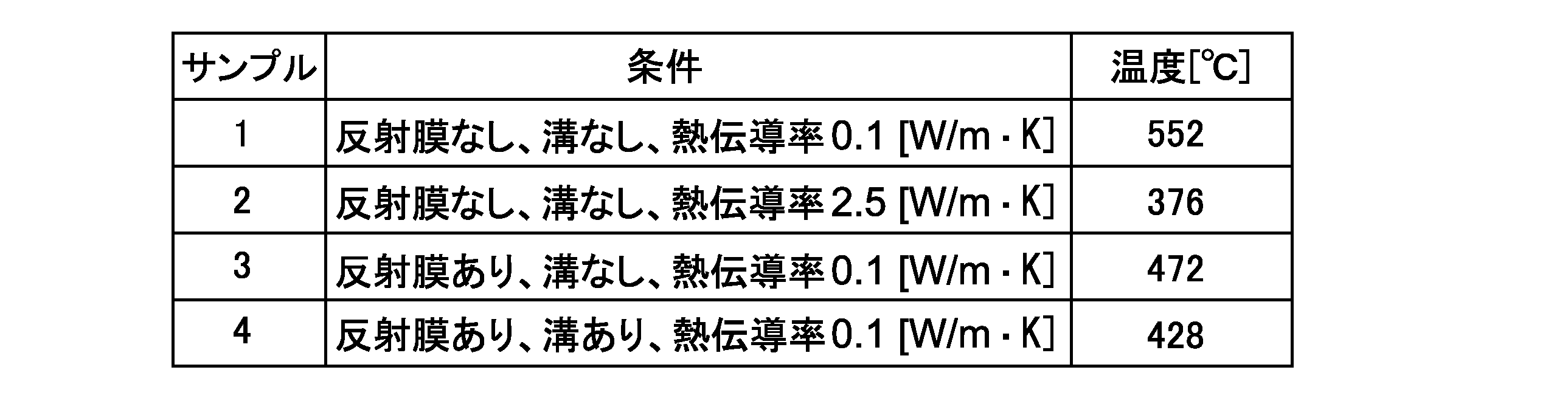
表2に示すように、光吸収層の熱伝導率が2.5W/m・Kのサンプル2では、比較的低い温度であることが確認された。一方、光吸収層の熱伝導率が同じ0.1W/m・Kであるサンプル1,3,4に関しては、反射膜及び溝のいずれもがないサンプル1で最も高い光吸収層の最高到達温度が得られた。このことから、反射膜及び溝の存在が光吸収層の放熱性を高め、蓄熱性を大きく低下させる要因となることが確認された。
以上のように本実施形態によれば、記録マークの形成に必要な蓄熱性と記録再生光の検出に必要な反射率特性とを兼ね備える光記録媒体を提供することができる。また上記各実験例は、単一の記録再生層113を有する光記録媒体を例に挙げて説明したが、多層の記録再生層113を有する光記録媒体についても同様な作用効果が得られる。特にレーザ入射側から最も遠い記録再生層の記録感度の向上を図ることができるため、多層化したときの記録感度の低下や記録再生特性の低下を抑制することができ、例えば6層以上の多層光記録媒体を構成することも可能となる。
以上、本発明の実施形態について説明したが、本発明は上述の実施形態にのみ限定されるものではなく、本発明の要旨を逸脱しない範囲内において種々変更を加え得ることは勿論である。
例えば以上の実施形態では、第1の光学調整層131と無機記録層133との間に光吸収層132が配置されたが、これに限られず、第1の光学調整層131と光吸収層132との間に無機記録層133が配置されてもよい。この場合においても記録再生光に対して十分な反射率を確保することができる。
また以上の実施形態では、光吸収層132が有機色素材料で構成されたが、金属酸化物等の無機材料で構成されてもよい。この場合も、熱伝導率が0.05[W/m・K]以上1.2[W/m・K]以下であることが好ましい。
10,11…光記録媒体 110…基材 112…ガイド層 113…記録再生層 114…中間層 115…保護層 116…バッファ層 120…反射膜 121…ガイドトラック 131…第1の光学調整層 132…光吸収層 133…無機記録層 134…第2の光学調整層
Claims (7)
- トラッキング制御用のガイドトラックと、前記ガ
イドトラックを被覆する金属材料で構成された反射膜とを有するガイド層と、 Bi及びOを少なくとも含む材料で構成された1以上の無機記録層と、 前記反射膜と前記無機記録層との間に配置され、金属酸化物材料で構成された第1の光学調整層と、 前記反射膜と前記第1の光学調整層との間に配置され、前記ガイドトラックの深さよりも大きい厚みを有するバッファ層と、 前記無機記録層に隣接して配置され、前記反射膜の熱伝導率よりも低い熱伝導率を有する光吸収層と を具備する光記録媒体。 - 請求項1に記載の光記録媒体であって、 前記光吸収層は、有機色素材料で構成される 光記録媒体。
- 請求項2に記載の光記録媒体であって、 前記光吸収層は、前記第1の光学調整層と前記無機記録層との間に配置される 光記録媒体。
- 請求項2に記載の光記録媒体であって、 前記無機記録層は、前記第1の光学調整層と前記光吸収層との間に配置される 光記録媒体。
- 請求項1から4のいずれか1項に記載の光記録媒体であって、 前記光吸収層の熱伝導率は、0.05[W/m・K]以上1.2[W/m・K]以下である 光記録媒体。
- 請求項5に記載の光記録媒体であって、 前記無機記録層の前記反射膜側とは反対側に配置され、金属酸化物材料で構成された第2の光学調整層をさらに具備する 光記録媒体。
- 請求項5に記載の光記録媒体であって、 前記無機記録層は、複数の無機記録層を含む 光記録媒体。
Applications Claiming Priority (2)
| Application Number | Priority Date | Filing Date | Title |
|---|---|---|---|
| JP2013-163796 | 2013-08-07 | ||
| JP2013163796A JP2015032340A (ja) | 2013-08-07 | 2013-08-07 | 光記録媒体 |
Publications (1)
| Publication Number | Publication Date |
|---|---|
| WO2015019927A1 true WO2015019927A1 (ja) | 2015-02-12 |
Family
ID=52461263
Family Applications (1)
| Application Number | Title | Priority Date | Filing Date |
|---|---|---|---|
| PCT/JP2014/070151 Ceased WO2015019927A1 (ja) | 2013-08-07 | 2014-07-31 | 光記録媒体 |
Country Status (2)
| Country | Link |
|---|---|
| JP (1) | JP2015032340A (ja) |
| WO (1) | WO2015019927A1 (ja) |
Families Citing this family (1)
| Publication number | Priority date | Publication date | Assignee | Title |
|---|---|---|---|---|
| JPWO2022186117A1 (ja) * | 2021-03-01 | 2022-09-09 |
Citations (2)
| Publication number | Priority date | Publication date | Assignee | Title |
|---|---|---|---|---|
| JP2005108396A (ja) * | 2003-04-15 | 2005-04-21 | Ricoh Co Ltd | 追記型光記録媒体とその記録再生方法 |
| JP2012164380A (ja) * | 2011-02-04 | 2012-08-30 | Tdk Corp | 光記録再生方法 |
-
2013
- 2013-08-07 JP JP2013163796A patent/JP2015032340A/ja active Pending
-
2014
- 2014-07-31 WO PCT/JP2014/070151 patent/WO2015019927A1/ja not_active Ceased
Patent Citations (2)
| Publication number | Priority date | Publication date | Assignee | Title |
|---|---|---|---|---|
| JP2005108396A (ja) * | 2003-04-15 | 2005-04-21 | Ricoh Co Ltd | 追記型光記録媒体とその記録再生方法 |
| JP2012164380A (ja) * | 2011-02-04 | 2012-08-30 | Tdk Corp | 光記録再生方法 |
Also Published As
| Publication number | Publication date |
|---|---|
| JP2015032340A (ja) | 2015-02-16 |
Similar Documents
| Publication | Publication Date | Title |
|---|---|---|
| JP2004213720A (ja) | 光記録媒体 | |
| WO2004093070A1 (ja) | 光記録媒体及びその記録再生方法 | |
| JP4667427B2 (ja) | 追記型光記録媒体 | |
| JP2005004944A (ja) | 光記録媒体及びその記録再生方法と装置 | |
| JP5094698B2 (ja) | 光情報記録媒体用色素及び光情報記録媒体 | |
| JP2003054135A (ja) | 光記録媒体および光記録方法 | |
| US7542404B2 (en) | Optical recording media | |
| JP4225996B2 (ja) | 光記録媒体、情報再生方法及び光情報再生装置 | |
| WO2015019927A1 (ja) | 光記録媒体 | |
| EP1624454A2 (en) | Optical information recording medium with thermosensitive mask layer, reproduction method and optical information processing device using the same | |
| JP2010033639A (ja) | 光情報記録媒体用色素及び光情報記録媒体 | |
| JP5283573B2 (ja) | 光情報記録媒体用色素及びそれを用いた光情報記録媒体 | |
| JP2008097794A (ja) | 片面2層光記録媒体 | |
| US7981494B2 (en) | Optical informaton recording medium | |
| JP2015035239A (ja) | 光記録媒体 | |
| JP5205521B2 (ja) | 光情報記録媒体用色素及びそれを用いた光情報記録媒体 | |
| JP2005302264A (ja) | 相変化型光情報記録媒体及び2層相変化型光情報記録媒体 | |
| JP2008262671A (ja) | 追記型光情報記録媒体 | |
| JP4232159B2 (ja) | 光記録媒体 | |
| JP2008090964A (ja) | 追記型2層構成光記録媒体 | |
| JP2008159207A (ja) | 光記録媒体及び光記録再生装置 | |
| JP2004213859A (ja) | 光記録媒体,光記録媒体の記録再生方法及び光記録媒体の記録再生装置 | |
| WO2014091845A1 (ja) | ガイド層分離型光記録媒体 | |
| JP2008097749A (ja) | 追記型光記録媒体 | |
| WO2015020135A1 (ja) | 光記録媒体 |
Legal Events
| Date | Code | Title | Description |
|---|---|---|---|
| 121 | Ep: the epo has been informed by wipo that ep was designated in this application |
Ref document number: 14833752 Country of ref document: EP Kind code of ref document: A1 |
|
| NENP | Non-entry into the national phase |
Ref country code: DE |
|
| 122 | Ep: pct application non-entry in european phase |
Ref document number: 14833752 Country of ref document: EP Kind code of ref document: A1 |