WO2015015868A1 - 負圧ポンプ及びシリンダヘッドカバー - Google Patents
負圧ポンプ及びシリンダヘッドカバー Download PDFInfo
- Publication number
- WO2015015868A1 WO2015015868A1 PCT/JP2014/063254 JP2014063254W WO2015015868A1 WO 2015015868 A1 WO2015015868 A1 WO 2015015868A1 JP 2014063254 W JP2014063254 W JP 2014063254W WO 2015015868 A1 WO2015015868 A1 WO 2015015868A1
- Authority
- WO
- WIPO (PCT)
- Prior art keywords
- clutch plate
- driven
- side clutch
- negative pressure
- housing
- Prior art date
- Legal status (The legal status is an assumption and is not a legal conclusion. Google has not performed a legal analysis and makes no representation as to the accuracy of the status listed.)
- Ceased
Links
Images
Classifications
-
- F—MECHANICAL ENGINEERING; LIGHTING; HEATING; WEAPONS; BLASTING
- F04—POSITIVE - DISPLACEMENT MACHINES FOR LIQUIDS; PUMPS FOR LIQUIDS OR ELASTIC FLUIDS
- F04B—POSITIVE-DISPLACEMENT MACHINES FOR LIQUIDS; PUMPS
- F04B37/00—Pumps having pertinent characteristics not provided for in, or of interest apart from, groups F04B25/00 - F04B35/00
- F04B37/10—Pumps having pertinent characteristics not provided for in, or of interest apart from, groups F04B25/00 - F04B35/00 for special use
- F04B37/14—Pumps having pertinent characteristics not provided for in, or of interest apart from, groups F04B25/00 - F04B35/00 for special use to obtain high vacuum
-
- F—MECHANICAL ENGINEERING; LIGHTING; HEATING; WEAPONS; BLASTING
- F04—POSITIVE - DISPLACEMENT MACHINES FOR LIQUIDS; PUMPS FOR LIQUIDS OR ELASTIC FLUIDS
- F04B—POSITIVE-DISPLACEMENT MACHINES FOR LIQUIDS; PUMPS
- F04B35/00—Piston pumps specially adapted for elastic fluids and characterised by the driving means to their working members, or by combination with, or adaptation to, specific driving engines or motors, not otherwise provided for
- F04B35/002—Piston pumps specially adapted for elastic fluids and characterised by the driving means to their working members, or by combination with, or adaptation to, specific driving engines or motors, not otherwise provided for driven by internal combustion engines
-
- F—MECHANICAL ENGINEERING; LIGHTING; HEATING; WEAPONS; BLASTING
- F04—POSITIVE - DISPLACEMENT MACHINES FOR LIQUIDS; PUMPS FOR LIQUIDS OR ELASTIC FLUIDS
- F04B—POSITIVE-DISPLACEMENT MACHINES FOR LIQUIDS; PUMPS
- F04B35/00—Piston pumps specially adapted for elastic fluids and characterised by the driving means to their working members, or by combination with, or adaptation to, specific driving engines or motors, not otherwise provided for
- F04B35/04—Piston pumps specially adapted for elastic fluids and characterised by the driving means to their working members, or by combination with, or adaptation to, specific driving engines or motors, not otherwise provided for the means being electric
- F04B35/045—Piston pumps specially adapted for elastic fluids and characterised by the driving means to their working members, or by combination with, or adaptation to, specific driving engines or motors, not otherwise provided for the means being electric using solenoids
-
- F—MECHANICAL ENGINEERING; LIGHTING; HEATING; WEAPONS; BLASTING
- F04—POSITIVE - DISPLACEMENT MACHINES FOR LIQUIDS; PUMPS FOR LIQUIDS OR ELASTIC FLUIDS
- F04B—POSITIVE-DISPLACEMENT MACHINES FOR LIQUIDS; PUMPS
- F04B37/00—Pumps having pertinent characteristics not provided for in, or of interest apart from, groups F04B25/00 - F04B35/00
- F04B37/10—Pumps having pertinent characteristics not provided for in, or of interest apart from, groups F04B25/00 - F04B35/00 for special use
- F04B37/14—Pumps having pertinent characteristics not provided for in, or of interest apart from, groups F04B25/00 - F04B35/00 for special use to obtain high vacuum
- F04B37/16—Means for nullifying unswept space
-
- F—MECHANICAL ENGINEERING; LIGHTING; HEATING; WEAPONS; BLASTING
- F04—POSITIVE - DISPLACEMENT MACHINES FOR LIQUIDS; PUMPS FOR LIQUIDS OR ELASTIC FLUIDS
- F04C—ROTARY-PISTON, OR OSCILLATING-PISTON, POSITIVE-DISPLACEMENT MACHINES FOR LIQUIDS; ROTARY-PISTON, OR OSCILLATING-PISTON, POSITIVE-DISPLACEMENT PUMPS
- F04C25/00—Adaptations of pumps for special use of pumps for elastic fluids
- F04C25/02—Adaptations of pumps for special use of pumps for elastic fluids for producing high vacuum
-
- F—MECHANICAL ENGINEERING; LIGHTING; HEATING; WEAPONS; BLASTING
- F04—POSITIVE - DISPLACEMENT MACHINES FOR LIQUIDS; PUMPS FOR LIQUIDS OR ELASTIC FLUIDS
- F04C—ROTARY-PISTON, OR OSCILLATING-PISTON, POSITIVE-DISPLACEMENT MACHINES FOR LIQUIDS; ROTARY-PISTON, OR OSCILLATING-PISTON, POSITIVE-DISPLACEMENT PUMPS
- F04C29/00—Component parts, details or accessories of pumps or pumping installations, not provided for in groups F04C18/00 - F04C28/00
- F04C29/0042—Driving elements, brakes, couplings, transmissions specially adapted for pumps
- F04C29/005—Means for transmitting movement from the prime mover to driven parts of the pump, e.g. clutches, couplings, transmissions
-
- F—MECHANICAL ENGINEERING; LIGHTING; HEATING; WEAPONS; BLASTING
- F16—ENGINEERING ELEMENTS AND UNITS; GENERAL MEASURES FOR PRODUCING AND MAINTAINING EFFECTIVE FUNCTIONING OF MACHINES OR INSTALLATIONS; THERMAL INSULATION IN GENERAL
- F16D—COUPLINGS FOR TRANSMITTING ROTATION; CLUTCHES; BRAKES
- F16D27/00—Magnetically- or electrically- actuated clutches; Control or electric circuits therefor
- F16D27/10—Magnetically- or electrically- actuated clutches; Control or electric circuits therefor with an electromagnet not rotating with a clutching member, i.e. without collecting rings
- F16D27/108—Magnetically- or electrically- actuated clutches; Control or electric circuits therefor with an electromagnet not rotating with a clutching member, i.e. without collecting rings with axially movable clutching members
- F16D27/112—Magnetically- or electrically- actuated clutches; Control or electric circuits therefor with an electromagnet not rotating with a clutching member, i.e. without collecting rings with axially movable clutching members with flat friction surfaces, e.g. discs
-
- F—MECHANICAL ENGINEERING; LIGHTING; HEATING; WEAPONS; BLASTING
- F16—ENGINEERING ELEMENTS AND UNITS; GENERAL MEASURES FOR PRODUCING AND MAINTAINING EFFECTIVE FUNCTIONING OF MACHINES OR INSTALLATIONS; THERMAL INSULATION IN GENERAL
- F16D—COUPLINGS FOR TRANSMITTING ROTATION; CLUTCHES; BRAKES
- F16D27/00—Magnetically- or electrically- actuated clutches; Control or electric circuits therefor
- F16D27/14—Details
-
- F—MECHANICAL ENGINEERING; LIGHTING; HEATING; WEAPONS; BLASTING
- F16—ENGINEERING ELEMENTS AND UNITS; GENERAL MEASURES FOR PRODUCING AND MAINTAINING EFFECTIVE FUNCTIONING OF MACHINES OR INSTALLATIONS; THERMAL INSULATION IN GENERAL
- F16D—COUPLINGS FOR TRANSMITTING ROTATION; CLUTCHES; BRAKES
- F16D27/00—Magnetically- or electrically- actuated clutches; Control or electric circuits therefor
- F16D27/10—Magnetically- or electrically- actuated clutches; Control or electric circuits therefor with an electromagnet not rotating with a clutching member, i.e. without collecting rings
- F16D27/108—Magnetically- or electrically- actuated clutches; Control or electric circuits therefor with an electromagnet not rotating with a clutching member, i.e. without collecting rings with axially movable clutching members
- F16D27/11—Magnetically- or electrically- actuated clutches; Control or electric circuits therefor with an electromagnet not rotating with a clutching member, i.e. without collecting rings with axially movable clutching members with conical friction surfaces, e.g. cone clutches
Definitions
- the present invention relates to a negative pressure pump and a cylinder head cover.
- Japanese Patent Application Laid-Open No. 2010-112337 discloses a vacuum pump (negative pressure pump) having a pump unit that generates a negative pressure when a rotational force is transmitted from a shaft connected to a power source.
- the clutch plate attached to the front end of the rotary shaft of the pump unit is pressed against the clutch plate attached to the front end of the shaft by a spring force to transmit the rotational force of the shaft to the pump unit.
- the clutch plate on the pump unit side is separated from the clutch plate on the shaft side by the force generated by the diaphragm, and energy loss due to driving the pump unit is lost. Reduced.
- An object of the present invention is to provide a negative pressure pump that suppresses the thrust force from acting on a drive shaft that is rotationally driven by a power source, and reduces energy loss of the power source by intermittently transmitting the rotation from the drive shaft.
- a cylinder head cover is provided.
- a negative pressure pump includes a housing in which a drive shaft that is rotationally driven by a power source is inserted and disposed, and a driven shaft that is formed in the housing.
- a pump unit that generates negative pressure by transmitting the rotation of the drive shaft, and a drive that is attached to the drive shaft, is movable in the axial direction of the drive shaft, rotates integrally with the drive shaft, and has magnetism
- An elastic body that presses and engages the driving-side clutch plate with the driven-side clutch plate by an elastic force; and a magnetic force that is fixed to the housing and resists the pressing force of the elastic body to generate the driving-side clutch Remove the plate from the driven side
- An electromagnet that is released from the engagement plate to release the engaged state, a first wall portion that is provided on the pump portion side of the housing and receives
- the driving side clutch plate is pressed against and engaged with the driven side clutch plate by the pressing force (elastic force) of the elastic body, whereby the rotation of the driving shaft is transmitted to the driven shaft.
- the pump unit generates negative pressure.
- the electromagnet when the electromagnet generates a magnetic force against the pressing force of the elastic body, the electromagnet attracts the magnetic drive side clutch plate, so that the drive side clutch plate is pulled away from the driven side clutch plate and the drive side clutch The engagement state between the plate and the driven clutch plate is released. Thereby, a pump part stops the production
- transmission of the rotation from the drive shaft with respect to a pump part can be interrupted, the energy loss of a motive power source can be reduced.
- the driven side clutch plate on which the pressing force of the elastic body acts is received by the first wall portion provided on the pump portion side of the housing.
- the end of the elastic body opposite to the pump part side is supported by the second wall part provided on the opposite side of the casing to the pump part side.
- the negative pressure pump according to the second aspect of the present invention is the negative pressure pump according to the first aspect, wherein all or part of the casing is a non-magnetic material.
- the casing is made of a non-magnetic material, the magnetic force generated from the electromagnet is not transmitted to the casing (in other words, the magnetic force is not dispersed).
- the clutch plate can be pulled away from the driven clutch plate.
- the negative pressure pump according to a third aspect of the present invention is the negative pressure pump according to the first aspect or the second aspect, in which the casing is supplied with the lubricant supplied into the pump portion from the pump portion. A flow path that leads to a contact surface between the side clutch plate and the driven side clutch plate is formed.
- the contact surface between the drive side clutch plate and the driven side clutch plate Can reduce wear. Further, heat generation due to friction between the drive side clutch plate and the driven side clutch plate is also suppressed.
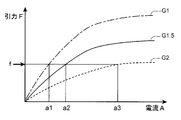
- the negative pressure pump according to a fourth aspect of the present invention is the negative pressure pump according to any one of the first to third aspects, according to the distance between the contact surfaces of the drive side clutch plate and the driven side clutch plate.
- the current applied to the electromagnet is varied.
- the attractive force (attractive force) due to the magnetic force of the electromagnet according to the distance between the contact surfaces of the drive side clutch plate and the driven side clutch plate (hereinafter referred to as “clutch gap” as appropriate).
- the strength of changes by changing the applied current to the electromagnet according to the clutch clearance, the attractive force acting on the drive side clutch plate can be maintained at a constant value (the attractive force sufficient to pull the drive side clutch plate away from the driven side clutch plate). This can improve power consumption.
- a cylinder head cover according to a fifth aspect of the present invention includes the negative pressure pump according to any one of the first to fourth aspects, and forms a part of the casing and is an engine cylinder head as a power source. Cover.
- the thrust force acts on the drive shaft that is rotationally driven by the engine as the power source.
- the energy loss of the engine can be reduced by suppressing the transmission of the rotation from the drive shaft while being suppressed. Thereby, the fuel consumption of an engine (vehicle) can be improved.
- the cylinder head cover forms a part of the housing, for example, the manufacturing cost can be reduced as compared with a case where the cylinder head cover and the negative pressure pump are separated.
- the energy loss of the power source is suppressed by suppressing the thrust force from acting on the drive shaft that is rotationally driven by the power source and intermittently transmitting the rotation from the drive shaft. Can be reduced.
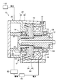
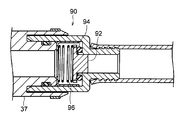
- FIG. 2 is a cross-sectional view along the axial direction of the negative pressure pump showing a state in which the drive side clutch plate is pulled away from the driven side clutch plate in the negative pressure pump of FIG. 1. It is sectional drawing along the flow-path direction of the check valve with which the negative pressure pump of FIG. 1 is provided. It is sectional drawing along the axial direction of the modification of the negative pressure pump of 1st Embodiment.
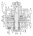
- FIG. 5 is a cross-sectional view along the axial direction of the negative pressure pump, showing a state in which the drive side clutch plate is pulled away from the driven side clutch plate in the negative pressure pump of FIG. 4.
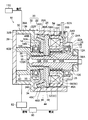
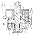
- the negative pressure pump 10 of this embodiment is a device that generates negative pressure by rotation of a drive shaft 100 that is driven to rotate in synchronization with a crankshaft of an engine (not shown) as a power source, and is a negative pressure brake for a vehicle. Used for the booster 110.
- this invention is not limited to the said structure, You may use a motor etc. as a motive power source of a negative pressure pump.
- the negative pressure pump 10 includes a housing 20, a pump unit 30 formed in the housing 20, a clutch 44 and a clutch intermittent mechanism 50 housed in the housing 20. is doing.
- the housing 20 includes a first housing 22 in which the drive shaft 100, the clutch 44, and the clutch engagement / disconnection mechanism 50 are disposed, and a second housing 32 that constitutes the pump unit 30.
- the first housing 22 includes a cylindrical portion 24 including one end portion 22 ⁇ / b> A in the axial direction (the right end portion in FIG. 1) and another portion and includes the other end portion 22 ⁇ / b> B in the axial direction. Also, it has a substantially cylindrical shape constituted by a cylindrical portion 26 having a large diameter. The drive shaft 100 is inserted into the cylindrical portion 26 through the cylindrical portion 24.
- An annular bearing 12 that rotatably supports the drive shaft 100 is attached to the inner peripheral surface 24A of the cylindrical portion 24 along the inner peripheral surface 24A.
- a projecting wall portion 28 that projects radially inward is provided at one end portion 22 ⁇ / b> A of the cylindrical portion 24.
- the overhanging wall portion 28 is in contact with the side surface 12A on one side (right side in FIG. 1) of the bearing 12 in the axial direction.
- the overhanging wall portion 28 restricts the movement of the bearing 12 in one axial direction.
- the overhanging wall portion 28 supports a coil spring 56 described later via the flange portion 102 and the bearing 14. That is, the spring force of the coil spring 56 is received by the overhanging wall portion 28.
- a flange portion 102 formed on the drive shaft 100 is in contact with the side surface 12B on the other side (left side in FIG. 1) of the bearing 12 in the axial direction.
- An annular member 54 to which an electromagnet 52 constituting the clutch engagement / disconnection mechanism 50 is attached is fixed to the one end 22A side of the cylindrical portion 26 along the inner peripheral surface 26A.
- the electromagnet 52 is a solenoid coil, and is accommodated in a hollow portion of an annular member 54 having a U-shaped cross section.
- the opening 54 ⁇ / b> A of the annular member 54 faces the other end 22 ⁇ / b> B side of the first housing 22. Further, the bottom portion 54 ⁇ / b> B of the annular member 54 is in contact with the step surface 25 formed by the difference in diameter between the cylindrical portion 24 and the cylindrical portion 26.
- a through-hole 54C for passing a cord 52A for applying a current to the electromagnet is formed in the bottom 54B of the annular member 54.
- the cord 52A passing through the through hole 54C is connected to the control unit 80 through the through hole 26B formed in the cylindrical portion 26.
- a water stop member (not shown) for preventing a lubricant (engine oil in this embodiment) from leaking out of the first housing 22 is disposed in the through hole 26B.
- a drive side clutch plate 46 constituting the clutch 44 is attached to the drive shaft 100 and disposed on the other end 22B side of the cylindrical portion 26 with respect to the annular member 54.
- the drive-side clutch plate 46 of the present embodiment includes a disc portion 46A and a tapered portion 46B that projects from the outer peripheral edge of the disc portion 46A in a tapered shape.
- the drive side clutch plate 46 is configured to be movable in the axial direction of the drive shaft 100 and to rotate integrally with the drive shaft 100.
- the drive side clutch plate 46 is made of a magnetic material (in this embodiment, iron).
- a coil spring (string winding spring) 56 is disposed between the annular member 54 and the drive shaft 100 so as to surround the drive shaft 100.
- the coil spring 56 is disposed between the flange portion 102 of the drive shaft 100 and the disk portion 46A of the drive side clutch plate 46, and one end portion 56A (the right end portion in FIG. 1) is a flange.
- the other end portion 56B is in contact with the plate member 47 attached to the disk portion 46A.
- the coil spring 56 is set to have a pressing force (spring force (elastic force)) such that the driving side clutch plate 46 is pressed against a driven side clutch plate 48 described later.
- the coil spring 56 constitutes the clutch engagement / disconnection mechanism 50.
- the coil spring 56 of this embodiment is an example of the elastic body of this invention.
- the electromagnet 52 described above can generate a magnetic force that is strong against the pressing force of the coil spring 56, and the driving side clutch plate 46 is attracted to the driven side clutch plate 46 by this magnetic force.
- the engagement state can be released by pulling away from the clutch plate 48 (details will be described later).
- the second housing 32 includes a cylindrical portion 34 including one end portion 32 ⁇ / b> A in the axial direction (the right end portion in FIG. 1) and the other end portion 32 ⁇ / b> B. Also, it has a substantially cylindrical shape composed of a cylindrical portion 36 having a large diameter.
- the second housing 32 is connected to the other end portion 22 ⁇ / b> B of the cylindrical portion 26 with the cylindrical portion 34 inserted into the first housing 22. From the inside of the cylindrical portion 36, the tip end portion 40 ⁇ / b> A of the driven shaft 40 extends into the cylindrical portion 26 through the cylindrical portion 34.
- An annular bearing 14 that rotatably supports the driven shaft 40 is attached to the inner peripheral surface 34A of the cylindrical portion 34 along the inner peripheral surface 34A. Further, on the other end side of the cylindrical portion 34, an overhanging wall portion 38 that projects radially inward is provided. The overhanging wall portion 38 is in contact with the side surface 14B on the other side (left side in FIG. 1) of the bearing 14 in the axial direction. The overhanging wall portion 38 restricts the movement of the bearing 14 toward the other side in the axial direction.
- a disk portion 48 ⁇ / b> A of a driven side clutch plate 48 attached to the driven shaft 40 is in contact with the side surface 14 ⁇ / b> A on one side (right side in FIG.
- the packing 15 is used to prevent engine oil from leaking out.
- the overhanging wall portion 38 receives the driven clutch plate 48 on which the pressing force of the coil spring 56 acts via the packing 15 and the bearing 14. That is, the spring force of the coil spring 56 is received by the overhanging wall portion 38.
- a lid 39 is attached to the other end portion 32 ⁇ / b> B of the cylindrical portion 36.
- the cylindrical portion 36 is provided with a suction port 37 (see FIG. 3) and a discharge port (not shown).
- the suction port 37 is connected to a negative pressure brake booster 110 through a check valve 90 having a check function.
- the check valve 90 allows the flow of fluid (here, air) from the negative pressure type brake booster 110 to the suction port 37 and stops the flow of fluid from the suction port 37 to the negative pressure type brake booster 110.
- a valve body 92, a valve seat 94 to which the valve body 92 is contacted and separated, and a spring 96 for pressing the valve body 92 against the valve seat 94 are configured.
- a base end portion 40B of the driven shaft 40 having a cylindrical shape is disposed inside the cylindrical portion 36.
- a groove (not shown) extending in the radial direction is formed in the base end portion 40B, and a plate-like vane 42 is slidably disposed in the groove extending direction. Thereby, the vane 42 receives the centrifugal force by the rotation of the driven shaft 40 and slides in the groove.
- the cylindrical portion 36 of the present embodiment is a long cylindrical shape
- the driven shaft 40 is a regular cylindrical shape. That is, the inner peripheral surface 36A of the cylindrical portion 36 has an elliptical cross-sectional shape, and the outer peripheral surface of the driven shaft 40 has a circular cross-sectional shape. For this reason, a space (gap) is generated between the inner peripheral surface 36 ⁇ / b> A of the cylindrical portion 36 and the outer peripheral surface of the driven shaft 40.
- the vane 42 receives the centrifugal force and moves outward from the groove of the base end portion 40B and moves along the inner peripheral surface 36A.
- the inner peripheral surface 36A and the driven shaft 40 Are divided into a plurality of spaces by the vanes 42.
- the suction port 37 is provided on the long axis of the cylindrical portion 36 and the discharge port (not shown) is provided on the short axis
- the partitioned space is the rotation of the driven shaft 40. Accordingly, the volume gradually decreases from the suction side to the discharge side, and a negative pressure is generated in the cylindrical portion 36 due to the volume change. That is, a negative pressure is generated by the pump unit 30 as the driven shaft 40 rotates.
- the pump unit 30 includes a second housing 32 (cylindrical portion 36), a suction port 37, a discharge port (not shown), a lid 39, a driven shaft 40, and a vane 42.
- the distal end portion 100A of the drive shaft 100 is inserted into the distal end portion 40A of the driven shaft 40.
- a packing 16 is closely disposed between the driven shaft 40 and the drive shaft 100. This packing 16 is used to prevent leakage of engine oil.
- a flow path 104 for guiding engine oil from the engine to the pump unit 30 is formed inside the drive shaft 100. The engine oil that has passed through the flow path 104 passes through the driven shaft 40 and is supplied into the cylindrical portion 36. Thereby, the frictional resistance between the inner peripheral surface 36A of the cylindrical portion 36 and the vane 42 can be reduced.
- a driven side clutch plate 48 constituting the clutch 44 is attached to the tip end portion 40A of the driven shaft 40.
- the driven side clutch plate 48 of the present embodiment includes a disc portion 48A and a tapered portion 48B that projects from the outer peripheral edge of the disc portion 48A in a tapered shape.
- the driven side clutch plate 48 is configured to be movable in the axial direction of the driven shaft 40 and to rotate integrally with the driven shaft 40.
- the driven side clutch plate 48 is formed of the same material as that of the drive side clutch plate 46.
- the first housing 22 and the second housing 32 are formed of a non-magnetic material (for example, aluminum or resin).
- the present invention is not limited to this configuration.
- connection between the first housing 22 and the second housing 32 can be, for example, bolted.
- first casing 22 and the second casing 32 when they are formed of a metal material, they may be connected by welding, and when the first casing 22 and the second casing 32 are formed of a resin material. May be connected by thermal welding. That is, any connection method may be used as long as the first housing 22 and the second housing 32 can be connected.
- the pump unit 30 is formed with a flow path 35 that guides engine oil supplied into the pump unit 30 from the pump unit 30 to a contact surface between the driving side clutch plate 46 and the driven side clutch plate 48.
- a groove is formed in the inner peripheral surface 34A of the cylindrical portion 34 along the axial direction, and the groove communicates with the inside of the cylindrical portion 36 and the inside of the first housing 22 (cylindrical portion 26).
- a flow path 35 is formed. The opening of the flow path 35 is formed in the vicinity of the contact surface between the drive side clutch plate 46 and the driven side clutch plate 48.
- the negative pressure pump 10 has a control unit 80.
- the control unit 80 is configured to control the current applied to the electromagnet 52.
- the control unit 80 applies a current when the negative pressure generated by the pump unit 30 exceeds a specified value. Specifically, the negative pressure generated by the pump unit 30 is measured by the pressure sensor 82, and when the measured value exceeds the specified value, a current is applied to the electromagnet.
- control unit 80 responds to a distance G (referred to as “clutch gap” hereinafter) G (see FIG. 2 as appropriate) between the contact surface 46C of the drive side clutch plate 46 and the contact surface 48C of the driven side clutch plate 48.
- the current applied to the electromagnet 52 is varied. Specifically, when the clutch gap G is large, the control unit 80 increases the current applied to the electromagnet 52 to increase the magnetic force, and when the clutch gap G is small, the control unit 80 reduces the current applied to the electromagnet 52 to weaken the magnetic force.
- the attractive force (attractive force) acting on the side clutch plate 46 is controlled to approach a constant value.
- the driving side clutch plate 46 is pressed against and engaged with the driven side clutch plate 48 by the pressing force (spring force) of the coil spring 56, whereby the rotation of the driving shaft 100 is transmitted to the driven shaft 40.
- the pump unit 30 generates a negative pressure.
- the electromagnet 52 when the electromagnet 52 generates a magnetic force that resists the spring force of the coil spring 56, the electromagnet 52 attracts the drive side clutch plate 46 by the magnetic force, so that the drive side clutch plate 46 is separated from the driven side clutch plate 48.
- the engaged state of the drive side clutch plate 46 and the driven side clutch plate 48 is released.
- the pump part 30 stops the production
- transmission of rotation from the drive shaft 100 to the pump unit 30 can be interrupted, so that energy loss of the engine as a power source can be reduced. Thereby, the fuel consumption of the vehicle can be improved.
- the driven clutch plate 48 on which the spring force of the coil spring 56 acts is received by the overhanging wall portion 38 provided in the second housing 32.
- one end portion 56 ⁇ / b> A of the coil spring 56 is supported by the overhanging wall portion 28 provided in the first housing 22.
- the drive-side clutch plate 46 that receives the spring force from the coil spring 56 and receives the magnetic force from the electromagnet 52 is movable in the axial direction of the drive shaft 100, whereby the spring force of the coil spring 56 and the electromagnet 52 are applied to the drive shaft 100.
- the thrust force due to the magnetic force is suppressed from acting.
- the driven side clutch plate 48 can be moved in the axial direction of the driven shaft 40, the spring force of the coil spring 56 is suppressed from acting on the driven shaft 40.
- the energy loss of the engine is suppressed by suppressing the thrust force from acting on the drive shaft 100 that is rotationally driven by the engine and intermittently transmitting the rotation from the drive shaft 100. Can be reduced.
- the first housing 22 and the second housing 32 are each made of a non-magnetic material, the magnetic force generated from the electromagnet 52 is not transmitted to the first housing 22 and the second housing 32 ( Therefore, the driving side clutch plate 46 can be separated from the driven side clutch plate 48 while suppressing power consumption.
- the engine oil is supplied from the pump unit 30 to the contact surface 46 ⁇ / b> C of the drive side clutch plate 46 and the contact surface 48 ⁇ / b> C of the driven side clutch plate 48 through the flow path 35.
- 46 and wear of the contact surfaces 46C and 48C of the driven side clutch plate 48 can be suppressed. Further, heat generation due to friction between the drive side clutch plate 46 and the driven side clutch plate 48 is also suppressed.
- both the drive side clutch plate 46 and the driven side clutch plate 48 are formed so as to be movable in the coaxial direction, the drive side clutch plate 46 can be smoothly engaged (re-fastened) with the driven side clutch plate 48. .
- the negative pressure pump 10 itself operates, so that the negative pressure brake booster 110 can be operated.
- the control unit 80 restarts the engine, for example, when the current is applied to the cell motor, the current is applied to the electromagnet 52 at the same time.
- the driving side clutch plate 46 is separated from the driven side clutch plate 48, so that the pump unit 30 does not operate when the engine is restarted, which affects the startability of the engine. None will happen.
- control unit 80 after the engine is started, for example, when the cell motor is turned off, the application of current to the electromagnet 52 is stopped, whereby the negative pressure pump 10 is operated by the power of the rotating engine. Further, at this time, by controlling the current so as to gradually decrease the current to the electromagnet 52, the vane 42 of the negative pressure pump 10 rotates slowly to discharge the engine oil in the pump unit 30 to the outside of the pump unit 30. Thus, damage to the pump unit 30 can be suppressed.
- the first housing 22 and the second housing 32 are formed of a nonmagnetic material.
- the present invention is not limited to this configuration, and only the first housing 22 is formed of a nonmagnetic material. It may be formed.
- the drive shaft 100 is inserted from the first housing 22 of the negative pressure pump 10, but the present invention is not limited to this configuration.
- the drive shaft 100 may be inserted from the second housing 32 as in the negative pressure pump 11 of the modification shown in FIGS. Specifically, as shown in FIGS. 4 and 5, in the negative pressure pump 11, the cylindrical portion 24 is closed by the overhanging wall portion 28 of the first housing 22, and instead the lid 39 of the second housing 32.
- the drive shaft 100 is inserted through the opening.
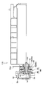
- the cylinder head cover 120 of this embodiment is used to cover the cylinder head of the engine.
- the cylinder head cover 120 includes the negative pressure pump 10 of the first embodiment.
- a part of the cylinder head cover 120 constitutes (also serves as) the first housing 22 of the negative pressure pump 10.
- the cylinder head cover 120 may be a magnetic material or a non-magnetic material, but is formed of resin in this embodiment.
- the effect of the cylinder head cover 120 of this embodiment is demonstrated. Since the cylinder head cover 120 includes the negative pressure pump 10, the thrust energy is suppressed from acting on the drive shaft 100 that is rotationally driven by the engine, and the transmission of rotation from the drive shaft 100 is interrupted to interrupt engine energy. Loss can be reduced. Thereby, the fuel consumption of an engine (vehicle) can be improved. In addition, since the cylinder head cover 120 forms the first housing 22, for example, the manufacturing cost can be reduced compared to a case where the cylinder head cover 120 and the negative pressure pump 10 are separated.
Landscapes
- Engineering & Computer Science (AREA)
- General Engineering & Computer Science (AREA)
- Mechanical Engineering (AREA)
- Physics & Mathematics (AREA)
- Electromagnetism (AREA)
- Combustion & Propulsion (AREA)
- Chemical & Material Sciences (AREA)
- Mechanical Operated Clutches (AREA)
- Details And Applications Of Rotary Liquid Pumps (AREA)
- Compressors, Vaccum Pumps And Other Relevant Systems (AREA)
- Applications Or Details Of Rotary Compressors (AREA)
- Hydraulic Clutches, Magnetic Clutches, Fluid Clutches, And Fluid Joints (AREA)
- Rotary Pumps (AREA)
Priority Applications (3)
| Application Number | Priority Date | Filing Date | Title |
|---|---|---|---|
| US14/888,991 US10233915B2 (en) | 2013-07-30 | 2014-05-19 | Negative pressure pump and cylinder head cover |
| EP14831527.8A EP2982864B1 (en) | 2013-07-30 | 2014-05-19 | Negative pressure pump and cylinder head cover |
| CN201480025115.4A CN105190032B (zh) | 2013-07-30 | 2014-05-19 | 负压泵及汽缸头盖 |
Applications Claiming Priority (2)
| Application Number | Priority Date | Filing Date | Title |
|---|---|---|---|
| JP2013157712A JP5799058B2 (ja) | 2013-07-30 | 2013-07-30 | 負圧ポンプ及びシリンダヘッドカバー |
| JP2013-157712 | 2013-07-30 |
Publications (1)
| Publication Number | Publication Date |
|---|---|
| WO2015015868A1 true WO2015015868A1 (ja) | 2015-02-05 |
Family
ID=52431414
Family Applications (1)
| Application Number | Title | Priority Date | Filing Date |
|---|---|---|---|
| PCT/JP2014/063254 Ceased WO2015015868A1 (ja) | 2013-07-30 | 2014-05-19 | 負圧ポンプ及びシリンダヘッドカバー |
Country Status (5)
| Country | Link |
|---|---|
| US (1) | US10233915B2 (enExample) |
| EP (1) | EP2982864B1 (enExample) |
| JP (1) | JP5799058B2 (enExample) |
| CN (1) | CN105190032B (enExample) |
| WO (1) | WO2015015868A1 (enExample) |
Cited By (1)
| Publication number | Priority date | Publication date | Assignee | Title |
|---|---|---|---|---|
| US10294454B2 (en) | 2016-08-24 | 2019-05-21 | General Electric Company | Methods and kits for cell activation |
Families Citing this family (6)
| Publication number | Priority date | Publication date | Assignee | Title |
|---|---|---|---|---|
| JP6549418B2 (ja) * | 2015-05-28 | 2019-07-24 | 三桜工業株式会社 | 負圧ポンプ |
| CN106246549B (zh) * | 2016-08-31 | 2018-11-30 | 上海肇民动力科技有限公司 | 真空泵 |
| US11529725B2 (en) * | 2017-10-20 | 2022-12-20 | Milwaukee Electric Tool Corporation | Power tool including electromagnetic clutch |
| EP3700713B1 (en) | 2017-10-26 | 2023-07-12 | Milwaukee Electric Tool Corporation | Kickback control methods for power tools |
| US11641102B2 (en) | 2020-03-10 | 2023-05-02 | Smart Wires Inc. | Modular FACTS devices with external fault current protection within the same impedance injection module |
| FR3131354B1 (fr) * | 2021-12-29 | 2024-02-09 | Valeo Embrayages | Ensemble d’actionnement et actionneur pour groupe motopropulseur |
Citations (4)
| Publication number | Priority date | Publication date | Assignee | Title |
|---|---|---|---|---|
| JPS5690435U (enExample) * | 1979-12-15 | 1981-07-18 | ||
| JPH0872700A (ja) * | 1994-08-31 | 1996-03-19 | Nabco Ltd | 負圧発生装置 |
| JP2010112337A (ja) | 2008-11-10 | 2010-05-20 | Nissan Motor Co Ltd | バキュームポンプ構造 |
| JP2013057293A (ja) * | 2011-09-08 | 2013-03-28 | Toyota Motor Corp | ウォータポンプ |
Family Cites Families (21)
| Publication number | Priority date | Publication date | Assignee | Title |
|---|---|---|---|---|
| US2230717A (en) * | 1939-10-24 | 1941-02-04 | Gilbert & Barker Mfg Co | Pumping means |
| US4009971A (en) * | 1974-06-07 | 1977-03-01 | Binks Manufacturing Company | Electric motor-driven, double-acting pump having pressure-responsive actuation |
| US4056178A (en) * | 1976-04-28 | 1977-11-01 | Eaton Corporation | Magnetically actuated viscous fluid coupling |
| JPS5751991A (en) * | 1980-09-12 | 1982-03-27 | Seiko Seiki Co Ltd | Bearing structure for gas compressor |
| US4516918A (en) * | 1982-05-25 | 1985-05-14 | Trw Inc. | Pump assembly |
| GB2162254B (en) * | 1984-03-30 | 1988-02-03 | Grau Girling Limited | Air compressor drive clutch |
| EP0284388A3 (en) * | 1987-03-26 | 1989-11-15 | Bendix Limited | Clutch driven compressor assembly |
| US4840543A (en) * | 1988-08-10 | 1989-06-20 | Geberth John Daniel Jun | Clutch apparatus for rapid power source conversion |
| EP0374268B1 (de) * | 1988-12-14 | 1992-05-06 | Christian Mayr GmbH & Co. KG | Selbsttätige Nachstellvorrichtung für elektromagnetisch betätigte Kupplungs- und/oder Bremsaggregate |
| US5989151A (en) * | 1998-08-11 | 1999-11-23 | Siemens Canada Limited | Hybrid engine cooling system having electric motor with electro-magnetic clutch |
| US6209700B1 (en) * | 1999-09-27 | 2001-04-03 | Tractech Inc. | Electric clutch including resilient disk biasing means |
| DE20221858U1 (de) * | 2002-12-21 | 2008-09-04 | Schaeffler Kg | Brennkraftmaschine mit einer Vorrichtung zur hydraulischen Drehwinkelverstellung ihrer Nockenwelle gegenüber ihrer Kurbelwelle sowie mit einer Vakuumpumpe für einen Servoverbraucher, insbesondere für einen Bremskraftverstärker |
| DE102006022472B3 (de) * | 2006-05-13 | 2008-02-07 | Gkn Driveline International Gmbh | Hydrostatische Kupplungsanordnung mit Zahnringmaschine |
| US8763734B2 (en) * | 2007-04-05 | 2014-07-01 | Haldex Brake Corporation | Drive through air compressor with cone clutch |
| JP2011220326A (ja) * | 2010-03-25 | 2011-11-04 | Aisin Seiki Co Ltd | 車両用ウォータポンプ |
| JP5447149B2 (ja) * | 2010-04-27 | 2014-03-19 | 大豊工業株式会社 | ベーンポンプ |
| EP2625440B1 (en) * | 2010-10-04 | 2020-01-08 | Litens Automotive Partnership | Driven component with clutch for selective operation of component |
| JP5776172B2 (ja) * | 2010-12-09 | 2015-09-09 | スズキ株式会社 | バキュームポンプの取付構造 |
| JP5482706B2 (ja) * | 2011-03-28 | 2014-05-07 | 株式会社豊田自動織機 | 変速機付き圧縮機 |
| DE112012001212T5 (de) * | 2011-04-13 | 2014-01-16 | Borgwarner Inc. | Reibungskupplungsanordnungen |
| JP5890186B2 (ja) | 2012-01-27 | 2016-03-22 | 京セラ株式会社 | 携帯端末、ロック状態制御プログラムおよびロック状態制御方法 |
-
2013
- 2013-07-30 JP JP2013157712A patent/JP5799058B2/ja not_active Expired - Fee Related
-
2014
- 2014-05-19 CN CN201480025115.4A patent/CN105190032B/zh not_active Expired - Fee Related
- 2014-05-19 US US14/888,991 patent/US10233915B2/en active Active
- 2014-05-19 EP EP14831527.8A patent/EP2982864B1/en not_active Not-in-force
- 2014-05-19 WO PCT/JP2014/063254 patent/WO2015015868A1/ja not_active Ceased
Patent Citations (4)
| Publication number | Priority date | Publication date | Assignee | Title |
|---|---|---|---|---|
| JPS5690435U (enExample) * | 1979-12-15 | 1981-07-18 | ||
| JPH0872700A (ja) * | 1994-08-31 | 1996-03-19 | Nabco Ltd | 負圧発生装置 |
| JP2010112337A (ja) | 2008-11-10 | 2010-05-20 | Nissan Motor Co Ltd | バキュームポンプ構造 |
| JP2013057293A (ja) * | 2011-09-08 | 2013-03-28 | Toyota Motor Corp | ウォータポンプ |
Cited By (1)
| Publication number | Priority date | Publication date | Assignee | Title |
|---|---|---|---|---|
| US10294454B2 (en) | 2016-08-24 | 2019-05-21 | General Electric Company | Methods and kits for cell activation |
Also Published As
| Publication number | Publication date |
|---|---|
| EP2982864A4 (en) | 2016-05-18 |
| US20160084244A1 (en) | 2016-03-24 |
| JP2015028305A (ja) | 2015-02-12 |
| JP5799058B2 (ja) | 2015-10-21 |
| EP2982864A1 (en) | 2016-02-10 |
| US10233915B2 (en) | 2019-03-19 |
| CN105190032A (zh) | 2015-12-23 |
| EP2982864B1 (en) | 2017-08-09 |
| CN105190032B (zh) | 2017-12-29 |
Similar Documents
| Publication | Publication Date | Title |
|---|---|---|
| JP5799058B2 (ja) | 負圧ポンプ及びシリンダヘッドカバー | |
| JP2018529915A (ja) | 粘性式クラッチ用のモーニングシックネスバルブシステム | |
| JP6324137B2 (ja) | シール機構付き車両用無段変速機 | |
| CN101258336A (zh) | 粘性离合器 | |
| JP2015028305A5 (enExample) | ||
| US11499594B2 (en) | Magnetorheological fluid clutch apparatus with low permeability drums | |
| JP5354081B1 (ja) | スタータ | |
| JP5310783B2 (ja) | 動力伝達装置 | |
| WO2015104866A1 (ja) | ウォーターポンプ | |
| JP5157465B2 (ja) | 自動変速機クラッチ圧制御用電磁弁装置 | |
| JP5784800B1 (ja) | 負圧ポンプの駆動制御方法 | |
| JP6549418B2 (ja) | 負圧ポンプ | |
| JP4199105B2 (ja) | 自動車用エンジンにおける位相可変装置の電磁ブレーキ冷却構造 | |
| JP5878403B2 (ja) | 可変容量型ポンプ | |
| JP5256814B2 (ja) | 可変フライホイール | |
| JP2014066180A (ja) | 電動ポンプ | |
| JP6244239B2 (ja) | シール機構付き車両用無段変速機 | |
| JP2009162326A (ja) | 動力伝達装置 | |
| JP2017227313A (ja) | 外部制御式流体継手 | |
| JP2011226499A (ja) | 電磁係合装置 | |
| JP6772475B2 (ja) | 電磁摩擦係合装置の制御装置及び制御方法 | |
| JP2010116966A (ja) | 駆動力配分装置 | |
| JP2013221540A (ja) | 駆動力伝達装置 | |
| JP2012026413A (ja) | 変速機付き圧縮機 | |
| JP2009192052A (ja) | 動力伝達装置 |
Legal Events
| Date | Code | Title | Description |
|---|---|---|---|
| WWE | Wipo information: entry into national phase |
Ref document number: 201480025115.4 Country of ref document: CN |
|
| 121 | Ep: the epo has been informed by wipo that ep was designated in this application |
Ref document number: 14831527 Country of ref document: EP Kind code of ref document: A1 |
|
| REEP | Request for entry into the european phase |
Ref document number: 2014831527 Country of ref document: EP |
|
| WWE | Wipo information: entry into national phase |
Ref document number: 2014831527 Country of ref document: EP |
|
| WWE | Wipo information: entry into national phase |
Ref document number: 14888991 Country of ref document: US |
|
| WWE | Wipo information: entry into national phase |
Ref document number: IDP00201507261 Country of ref document: ID |
|
| NENP | Non-entry into the national phase |
Ref country code: DE |