EP2982864B1 - Negative pressure pump and cylinder head cover - Google Patents
Negative pressure pump and cylinder head cover Download PDFInfo
- Publication number
- EP2982864B1 EP2982864B1 EP14831527.8A EP14831527A EP2982864B1 EP 2982864 B1 EP2982864 B1 EP 2982864B1 EP 14831527 A EP14831527 A EP 14831527A EP 2982864 B1 EP2982864 B1 EP 2982864B1
- Authority
- EP
- European Patent Office
- Prior art keywords
- clutch plate
- side clutch
- driven
- negative pressure
- drive
- Prior art date
- Legal status (The legal status is an assumption and is not a legal conclusion. Google has not performed a legal analysis and makes no representation as to the accuracy of the status listed.)
- Not-in-force
Links
Images


Classifications
-
- F—MECHANICAL ENGINEERING; LIGHTING; HEATING; WEAPONS; BLASTING
- F04—POSITIVE - DISPLACEMENT MACHINES FOR LIQUIDS; PUMPS FOR LIQUIDS OR ELASTIC FLUIDS
- F04B—POSITIVE-DISPLACEMENT MACHINES FOR LIQUIDS; PUMPS
- F04B37/00—Pumps having pertinent characteristics not provided for in, or of interest apart from, groups F04B25/00 - F04B35/00
- F04B37/10—Pumps having pertinent characteristics not provided for in, or of interest apart from, groups F04B25/00 - F04B35/00 for special use
- F04B37/14—Pumps having pertinent characteristics not provided for in, or of interest apart from, groups F04B25/00 - F04B35/00 for special use to obtain high vacuum
-
- F—MECHANICAL ENGINEERING; LIGHTING; HEATING; WEAPONS; BLASTING
- F04—POSITIVE - DISPLACEMENT MACHINES FOR LIQUIDS; PUMPS FOR LIQUIDS OR ELASTIC FLUIDS
- F04B—POSITIVE-DISPLACEMENT MACHINES FOR LIQUIDS; PUMPS
- F04B35/00—Piston pumps specially adapted for elastic fluids and characterised by the driving means to their working members, or by combination with, or adaptation to, specific driving engines or motors, not otherwise provided for
- F04B35/002—Piston pumps specially adapted for elastic fluids and characterised by the driving means to their working members, or by combination with, or adaptation to, specific driving engines or motors, not otherwise provided for driven by internal combustion engines
-
- F—MECHANICAL ENGINEERING; LIGHTING; HEATING; WEAPONS; BLASTING
- F04—POSITIVE - DISPLACEMENT MACHINES FOR LIQUIDS; PUMPS FOR LIQUIDS OR ELASTIC FLUIDS
- F04B—POSITIVE-DISPLACEMENT MACHINES FOR LIQUIDS; PUMPS
- F04B35/00—Piston pumps specially adapted for elastic fluids and characterised by the driving means to their working members, or by combination with, or adaptation to, specific driving engines or motors, not otherwise provided for
- F04B35/04—Piston pumps specially adapted for elastic fluids and characterised by the driving means to their working members, or by combination with, or adaptation to, specific driving engines or motors, not otherwise provided for the means being electric
- F04B35/045—Piston pumps specially adapted for elastic fluids and characterised by the driving means to their working members, or by combination with, or adaptation to, specific driving engines or motors, not otherwise provided for the means being electric using solenoids
-
- F—MECHANICAL ENGINEERING; LIGHTING; HEATING; WEAPONS; BLASTING
- F04—POSITIVE - DISPLACEMENT MACHINES FOR LIQUIDS; PUMPS FOR LIQUIDS OR ELASTIC FLUIDS
- F04C—ROTARY-PISTON, OR OSCILLATING-PISTON, POSITIVE-DISPLACEMENT MACHINES FOR LIQUIDS; ROTARY-PISTON, OR OSCILLATING-PISTON, POSITIVE-DISPLACEMENT PUMPS
- F04C25/00—Adaptations of pumps for special use of pumps for elastic fluids
- F04C25/02—Adaptations of pumps for special use of pumps for elastic fluids for producing high vacuum
-
- F—MECHANICAL ENGINEERING; LIGHTING; HEATING; WEAPONS; BLASTING
- F04—POSITIVE - DISPLACEMENT MACHINES FOR LIQUIDS; PUMPS FOR LIQUIDS OR ELASTIC FLUIDS
- F04C—ROTARY-PISTON, OR OSCILLATING-PISTON, POSITIVE-DISPLACEMENT MACHINES FOR LIQUIDS; ROTARY-PISTON, OR OSCILLATING-PISTON, POSITIVE-DISPLACEMENT PUMPS
- F04C29/00—Component parts, details or accessories of pumps or pumping installations, not provided for in groups F04C18/00 - F04C28/00
- F04C29/0042—Driving elements, brakes, couplings, transmissions specially adapted for pumps
- F04C29/005—Means for transmitting movement from the prime mover to driven parts of the pump, e.g. clutches, couplings, transmissions
-
- F—MECHANICAL ENGINEERING; LIGHTING; HEATING; WEAPONS; BLASTING
- F16—ENGINEERING ELEMENTS AND UNITS; GENERAL MEASURES FOR PRODUCING AND MAINTAINING EFFECTIVE FUNCTIONING OF MACHINES OR INSTALLATIONS; THERMAL INSULATION IN GENERAL
- F16D—COUPLINGS FOR TRANSMITTING ROTATION; CLUTCHES; BRAKES
- F16D27/00—Magnetically- or electrically- actuated clutches; Control or electric circuits therefor
- F16D27/10—Magnetically- or electrically- actuated clutches; Control or electric circuits therefor with an electromagnet not rotating with a clutching member, i.e. without collecting rings
- F16D27/108—Magnetically- or electrically- actuated clutches; Control or electric circuits therefor with an electromagnet not rotating with a clutching member, i.e. without collecting rings with axially movable clutching members
- F16D27/112—Magnetically- or electrically- actuated clutches; Control or electric circuits therefor with an electromagnet not rotating with a clutching member, i.e. without collecting rings with axially movable clutching members with flat friction surfaces, e.g. discs
-
- F—MECHANICAL ENGINEERING; LIGHTING; HEATING; WEAPONS; BLASTING
- F16—ENGINEERING ELEMENTS AND UNITS; GENERAL MEASURES FOR PRODUCING AND MAINTAINING EFFECTIVE FUNCTIONING OF MACHINES OR INSTALLATIONS; THERMAL INSULATION IN GENERAL
- F16D—COUPLINGS FOR TRANSMITTING ROTATION; CLUTCHES; BRAKES
- F16D27/00—Magnetically- or electrically- actuated clutches; Control or electric circuits therefor
- F16D27/14—Details
-
- F—MECHANICAL ENGINEERING; LIGHTING; HEATING; WEAPONS; BLASTING
- F04—POSITIVE - DISPLACEMENT MACHINES FOR LIQUIDS; PUMPS FOR LIQUIDS OR ELASTIC FLUIDS
- F04B—POSITIVE-DISPLACEMENT MACHINES FOR LIQUIDS; PUMPS
- F04B37/00—Pumps having pertinent characteristics not provided for in, or of interest apart from, groups F04B25/00 - F04B35/00
- F04B37/10—Pumps having pertinent characteristics not provided for in, or of interest apart from, groups F04B25/00 - F04B35/00 for special use
- F04B37/14—Pumps having pertinent characteristics not provided for in, or of interest apart from, groups F04B25/00 - F04B35/00 for special use to obtain high vacuum
- F04B37/16—Means for nullifying unswept space
-
- F—MECHANICAL ENGINEERING; LIGHTING; HEATING; WEAPONS; BLASTING
- F16—ENGINEERING ELEMENTS AND UNITS; GENERAL MEASURES FOR PRODUCING AND MAINTAINING EFFECTIVE FUNCTIONING OF MACHINES OR INSTALLATIONS; THERMAL INSULATION IN GENERAL
- F16D—COUPLINGS FOR TRANSMITTING ROTATION; CLUTCHES; BRAKES
- F16D27/00—Magnetically- or electrically- actuated clutches; Control or electric circuits therefor
- F16D27/10—Magnetically- or electrically- actuated clutches; Control or electric circuits therefor with an electromagnet not rotating with a clutching member, i.e. without collecting rings
- F16D27/108—Magnetically- or electrically- actuated clutches; Control or electric circuits therefor with an electromagnet not rotating with a clutching member, i.e. without collecting rings with axially movable clutching members
- F16D27/11—Magnetically- or electrically- actuated clutches; Control or electric circuits therefor with an electromagnet not rotating with a clutching member, i.e. without collecting rings with axially movable clutching members with conical friction surfaces, e.g. cone clutches
Definitions
- the present invention relates to a negative pressure pump and a cylinder head cover.
- JP-ANo. 2010-112337 there is disclosed a vacuum (negative pressure pump) having a pump portion that produces negative pressure as a result of a rotational force being transmitted to it from a shaft coupled to a motive power source.
- This vacuum pump transmits the rotational force of the shaft to the pump portion by using a spring force to press a clutch plate attached to the distal end of a rotating shaft of the pump portion against a clutch plate attached to the distal end of the shaft.
- a negative pressure pump of a first aspect of the present invention comprises: a casing inside of which a drive shaft driven to rotate by a motive power source is inserted and disposed; a pump portion that is formed in the casing, is equipped with a driven shaft, and produces negative pressure as a result of the rotation of the drive shaft being transmitted to the driven shaft; a drive-side clutch plate that is attached to the drive shaft, is movable in an axial direction of the drive shaft, rotates integrally with the drive shaft, and is magnetic; a driven-side clutch plate that is attached to the driven shaft, rotates integrally with the driven shaft, and transmits the rotation from the drive shaft to the driven shaft as a result of the drive-side clutch plate becoming engaged with the driven-side clutch plate; an elastic body which, by means of its elastic force, presses the drive-side clutch plate against the driven-side clutch plate to cause the drive-side clutch plate to engage with the driven-side clutch plate; an electromagnet that is fixed to the casing, produces a magnetic force counter to the pressing force of the elastic
- the drive-side clutch plate is pressed against, and engages with, the driven-side clutch plate by the pressing force (elastic force) of the elastic body, and thus the rotation of the drive shaft is transmitted to the driven shaft and the pump portion produces negative pressure.
- the electromagnet When the electromagnet produces the magnetic force counter to the pressing force of the elastic body, the electromagnet attracts the drive-side clutch plate that is magnetic, so the drive-side clutch plate is pulled away from the driven-side clutch plate and the state of engagement between the drive-side clutch plate and the driven-side clutch plate is canceled. Because of this, the pump portion stops producing negative pressure.
- the negative pressure pump can intermittently transmit the rotation from the drive shaft to the pump portion, so energy loss of the motive power source can be reduced.
- the driven-side clutch plate on which the pressing force of the elastic body acts is received by the first wall portion disposed on the pump portion side of the casing.
- the end portion of the elastic body on the opposite side of the pump portion side is supported by the second wall portion disposed on the opposite side of the pump portion side of the casing.
- a negative pressure pump of a second aspect of the present invention is the negative pressure pump of the first aspect in which, all or part of the casing is a nonmagnetic body.
- the casing is a nonmagnetic body, the magnetic force produced from the electromagnet is not transmitted to the casing (in other words, the magnetic force is not dispersed), so power consumption can be controlled and the drive-side clutch plate can be pulled away from the driven-side clutch plate.
- a negative pressure pump of a third aspect of the present invention is the negative pressure pump of the first aspect or the second aspect in which, a flow path that guides a lubricant supplied into the pump portion from the pump portion to contact surfaces of the drive-side clutch plate and the driven-side clutch plate is formed in the casing.
- the lubricant is guided, through the flow path, from the pump portion to the contact surfaces of the drive-side clutch plate and the driven-side clutch plate, so wear on the contact surfaces of the drive-side clutch plate and the driven-side clutch plate is controlled. Furthermore, heat produced by friction between the drive-side clutch plate and the driven-side clutch plate is also controlled.
- a negative pressure pump of a fourth aspect of the present invention is the negative pressure pump of any one aspect of the first to third aspects in which, the negative pressure pump changes a current applied to the electromagnet in accordance with a distance between contact surfaces of the drive-side clutch plate and the driven-side clutch plate.
- the intensity of the attractive force (force of attraction) resulting from the magnetic force of the electromagnet changes in accordance with the distance (hereinafter appropriately called a "clutch gap") between the contact surfaces of the drive-side clutch plate and the driven-side clutch plate.
- aclutch gap the distance between the contact surfaces of the drive-side clutch plate and the driven-side clutch plate.
- a cylinder head cover of a fifth aspect of the present invention is equipped with the negative pressure pump of any one aspect of the first to fourth aspects, forms part of the casing, and covers a cylinder head of an engine serving as a motive power source.
- the cylinder head cover of the fifth aspect is equipped with the negative pressure pump of any one aspect of the first to fourth aspects, the action of the thrust force on the drive shaft driven to rotate by the engine serving as the motive power source can be controlled, and energy loss of the engine can be reduced by intermittently transmitting the rotation from the drive shaft. Because of this, the fuel economy of the engine (vehicle) can be improved.
- the cylinder head cover forms part of the casing, manufacturing costs can be reduced compared, for example, to a configuration where the cylinder head cover and the negative pressure pump are separate bodies.
- the negative pressure pump and the cylinder head cover of the present invention can control the action of the thrust force on the drive shaft driven to rotate by the motive power source and reduce energy loss of the motive power source by intermittently transmitting the rotation from the drive shaft.
- a negative pressure pump of a first embodiment of the present invention will be described in accordance with FIG. 1 to FIG. 3 .
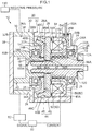
- a negative pressure pump 10 of the present embodiment is a device that produces negative pressure by the rotation of a drive shaft 100 driven to rotate synchronously with a crankshaft of an engine (not illustrated in the drawings) serving as a motive power source, and is used in a negative pressure brake booster 110 of a vehicle. It should be noted that the present invention is not limited to this configuration, and a motor or the like may also be used as the motive power source of the negative pressure pump.
- the negative pressure pump 10 has a casing 20, a pump portion 30 that is formed in the casing 20, and a clutch 44 and a clutch intermittent mechanism 50 that are housed in the casing 20.
- the casing 20 is configured by a first casing 22, inside of which the drive shaft 100, the clutch 44, and the clutch intermittent mechanism 50 are housed, and a second casing 32, which configures the pump portion 30.
- the first casing 22 is formed in a substantially cylindrical shape and is configured by a cylinder portion 24, which includes one axial direction end portion 22A (the end portion on the right side in FIG. 1 ) of the first casing 22, and a cylinder portion 26, which forms the other section of the first casing 22, includes the other axial direction end portion 22B of the first casing 22, and is larger in diameter than the cylinder portion 24.
- the drive shaft 100 is inserted through the cylinder portion 24 and disposed inside the cylinder portion 26.
- An annular bearing 12 that rotatably supports the drive shaft 100 along an inner peripheral surface 24A of the cylinder portion 24 is attached to the inner peripheral surface 24A. Furthermore, a jutting wall portion 28 that juts inward in the radial direction is disposed on the one end portion 22A of the cylinder portion 24. The jutting wall portion 28 is in contact with a side surface 12A on one axial direction side (the right side in FIG. 1 ) of the bearing 12. Because of this jutting wall portion 28, the movement of the bearing 12 toward the one axial direction side is limited. It should be noted that the jutting wall portion 28 supports a later-described coil spring 56 via a flange portion 102 and a bearing 14. That is, the spring force of the coil spring 56 is received by the jutting wall portion 28.
- the flange portion 102 which is formed on the drive shaft 100, is in contact with a side surface 12B on the other axial direction side (the left side in FIG. 1 ) of the bearing 12.
- An annular member 54 to which an electromagnet 52 that configures the clutch intermittent mechanism 50 is attached, is fixed along an inner peripheral surface 26A of the cylinder portion 26 to the one end portion 22A side of the cylinder portion 26.
- the electromagnet 52 is a solenoid coil and is housed in a recessed section of the annular member 54, which is formed in a cross-sectionally U-shape.
- An open portion 54A of the annular member 54 faces the other end portion 22B side of the first casing 22.
- a bottom portion 54B of the annular member 54 is in contact with a step surface 25 formed by the difference in diameter between the cylinder portion 24 and the cylinder portion 26.
- a through hole 54C for passing through a cord 52A for applying a current to the electromagnet is formed in the bottom portion 54B of the annular member 54.
- the cord 52A passing through the through hole 54C passes through a through hole 26B formed in the cylinder portion 26 and is connected to a control unit 80.
- a waterproof member (not illustrated in the drawings) for preventing a later-described lubricant (in the present embodiment, engine oil) from leaking out from the first casing 22 is disposed in the through hole 26B.
- a drive-side clutch plate 46 that configures the clutch 44 is attached to the drive shaft 100 and disposed nearer to the other end side 22B of the cylinder portion 26 than the annular member 54.
- the drive-side clutch plate 46 of the present embodiment is configured by a disc portion 46A and a tapered portion 46B that juts out in a tapered shape from the outer peripheral edge portion of the disc portion 46A.
- the drive-side clutch plate 46 is movable in the axial direction of the drive shaft 100 and is configured to rotate integrally with the drive shaft 100.
- the drive-side clutch plate 46 is formed by a material that is magnetic (in the present embodiment, iron).
- the coil spring 56 is disposed between the annular member 54 and the drive shaft 100 in such a way as to surround the drive shaft 100. Specifically, the coil spring 56 is disposed between the flange portion 102 of the drive shaft 100 and the disc portion 46A of the drive-side clutch plate 46, has one end portion 56A (the end portion on the right side in FIG. 1 ) in contact with the flange portion 102, and has another end portion 56B in contact with a plate 47 attached to the disc portion 46A.
- the pressing force (spring force (elastic force)) of the coil spring 56 is set in such a way that the coil spring 56 presses the drive-side clutch plate 46 against a later-described driven-side clutch plate 48 and causes the drive-side clutch plate 46 to engage with the driven-side clutch plate 48. It should be noted that the coil spring 56 configures the clutch intermittent mechanism 50. Furthermore, the coil spring 56 of the present embodiment is an example of an elastic body of the present invention.
- the aforementioned electromagnet 52 can produce a magnetic force of an intensity countering the pressing force of the coil spring 56 and is configured in such a way that, by attracting by means of this magnetic force the drive-side clutch plate 46, it can pull the drive-side clutch plate 46 away from the driven-side clutch plate 48 and cancel the state of engagement between them (details described later).
- the second casing 32 is formed in a substantially cylindrical shape and is configured by a cylinder portion 34, which includes one axial direction end portion 32A (the end portion on the right side in FIG. 1 ) of the second casing 32, and a cylinder portion 36, which forms the other section of the second casing 32, includes the other axial direction end portion 32B of the second casing 32, and is larger in diameter than the cylinder portion 34.
- the second casing 32 is connected to the other end portion 22B of the cylinder portion 26 in a state in which the cylinder portion 34 has been inserted inside the first casing 22.
- a distal end portion 40A of a driven shaft 40 extends from the inside of the cylinder portion 36, through the cylinder portion 34, and into the cylinder portion 26.
- An annular bearing 14 that rotatably supports the driven shaft 40 along an inner peripheral surface 34A of the cylinder portion 34 is attached to the inner peripheral surface 34A. Furthermore, a jutting wall portion 38 that juts inward in the radial direction is disposed on the other end side of the cylinder portion 34. The jutting wall portion 38 is in contact with a side surface 14B on the other axial direction side (the left side in FIG. 1 ) of the bearing 14. Because of this jutting wall portion 38, the movement of the bearing 14 toward the other axial direction side is limited.
- a disc portion 48A of the driven-side clutch plate 48 attached to the driven shaft 40 is in contact, via a packing 15, with a side surface 14A on one axial direction side (the right side in FIG. 1 ) of the bearing 14. It should be noted that the packing 15 is used to prevent leakage of the engine oil.
- the aforementioned jutting wall portion 38 receives, via the packing 15 and the bearing 14, the driven-side clutch plate 48 on which the pressing force of the coil spring 56 acts. That is, the spring force of the coil spring 56 is received by the jutting wall portion 38.
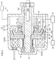
- a cover 39 is attached to the other end portion 32B of the cylinder portion 36. Furthermore, a suction port 37 (see FIG. 3 ) and a discharge port (not illustrated in the drawings) are disposed in the cylinder portion 36. The suction port 37 is connected to the negative pressure brake booster 110 via a check valve 90 having a check function.
- the check valve 90 is configured by a valve element 92, a valve seat 94 with which the valve element 92 is brought into contact and from which the valve element 92 is separated, and a spring 96 for pressing the valve element 92 against the valve seat 94, so that the check valve 90 allows the flow of a fluid (here, air) from the negative pressure brake booster 110 toward the suction port 37 and stops the flow of the fluid from the suction port 37 toward the negative pressure brake booster 110.
- a fluid here, air
- a base end portion 40B of the driven shaft 40 formed in a cylindrical shape is disposed inside the cylinder portion 36.
- a groove (not illustrated in the drawings) that extends in the radial direction is formed in the base end portion 40B, and a plate-shaped vane 42 is disposed in the groove so as to be slidable in the groove extension direction. Because of this, the vane 42 receives centrifugal force because of the rotation of the driven shaft 40 and slides in the groove.
- the cylinder portion 36 of the present embodiment is formed in an elliptical cylindrical shape, and the driven shaft 40 is formed in a perfectly circular cylindrical shape. That is, the cross-sectional shape of an inner peripheral surface 36A of the cylinder portion 36 is an ellipse, and the cross-sectional shape of the outer peripheral surface of the driven shaft 40 is a perfect circle. For this reason, a space (gap) occurs between the inner peripheral surface 36A of the cylinder portion 36 and the outer peripheral surface of the driven shaft 40.
- the vane 42 receives centrifugal force, moves outward from the groove in the base end portion 40B, and moves along the inner peripheral surface 36A, so the space between the inner peripheral surface 36A and the driven shaft 40 becomes partitioned into plural spaces by the vane 42.
- the suction port 37 is disposed on the major axis of the cylinder portion 36 and the discharge port (not illustrated in the drawings) is disposed on the minor axis, the capacities of the partitioned spaces gradually become smaller from the suction side toward the discharge side in accompaniment with the rotation of the driven shaft 40, and because of that change in capacity, negative pressure is produced by the cylinder portion 36.
- the pump portion 30 is configured by the second casing 32 (the cylinder portion 36), the suction port 37, the discharge port (not illustrated in the drawings), the cover 39, the driven shaft 40, and the vane 42.
- a distal end portion 100A of the drive shaft 100 is inserted inside the distal end portion 40A of the driven shaft 40. Furthermore, a packing 16 is disposed between and in close contact with the driven shaft 40 and the drive shaft 100. The packing 16 is used to prevent leakage of the engine oil.
- a flow path 104 for guiding the engine oil from the engine to the pump portion 30 is formed inside the drive shaft 100.
- the engine oil traveling through the flow path 104 travels through the inside of the driven shaft 40 and is supplied into the cylinder portion 34. Because of this, frictional resistance between the inner peripheral surface 36A of the cylinder portion 36 and the vane 42 can be reduced.
- the driven-side clutch plate 48 that configures the clutch 44 is attached to the distal end portion 40A of the driven shaft 40.
- the driven-side clutch plate 48 of the present embodiment is configured by the disc portion 48A and a tapered portion 48B that juts out in a tapered shape from the outer peripheral edge portion of the disc portion 48A.
- the driven-side clutch plate 48 is movable in the axial direction of the driven shaft 40 and is configured to rotate integrally with the driven shaft 40.
- the driven-side clutch plate 48 is formed by the same material as the drive-side clutch plate 46.
- the first casing 22 and the second casing 32 are formed by nonmagnetic bodies (e.g., aluminum, resin). It should be noted that the present invention is not limited to this configuration.
- the first casing 22 and the second casing 32 may also be formed by magnetic bodies (e.g., iron).
- first casing 22 and the second casing 32 can be accomplished with bolts, for example.
- first casing 22 and the second casing 32 may be connected to one another by welding, and in a case where the first casing 22 and the second casing 32 are formed by a resin material, they may connected to one another by thermal fusing. That is, any method may be used to connect the first casing 22 and the second casing 32 to one another as long as it is one with which they can be connected to one another.
- a flow path 35 that guides the engine oil supplied into the pump portion 30 from the pump portion 30 to between contact surfaces of the drive-side clutch plate 46 and the driven-side clutch plate 48 is formed in the pump portion 30.
- a groove is formed along the axial direction in the inner peripheral surface 34A of the cylinder portion 34, and this groove forms the flow path 35 that communicates the inside of the cylinder portion 36 with the inside of the first casing 22 (the cylinder portion 26).
- the opening of the flow path 35 is formed in the neighborhood between the contact surfaces of the drive-side clutch plate 46 and the driven-side clutch plate 48.
- the negative pressure pump 10 has the control unit 80.
- the control unit 80 is configured to control the current applied to the electromagnet 52.
- the control unit 80 applies the current when the negative pressure produced by the pump portion 80 exceeds a prescribed value.
- the negative pressure produced by the pump portion 80 is measured by a pressure sensor 82, and the control unit 80 applies the current to the electromagnet when the measured value exceeds the prescribed value.
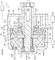
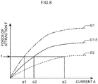
- control unit 80 changes the current applied to the electromagnet 52 in accordance with the distance (hereinafter appropriately called a "clutch gap") G (see FIG. 2 ) between a contact surface 46C of the drive-side clutch plate 46 and a contact surface 48C of the driven-side clutch plate 48.
- the control unit 80 performs control in such a way as bring the attractive force (force of attraction) acting on the drive-side clutch plate 46 closer to a constant value by increasing the current applied to the electromagnet 52 to make the magnetic force stronger when the clutch gap G is large and reducing the current applied to the electromagnet 52 to make the magnetic force weaker when the clutch gap G is small.
- An example of the method of control performed by the control unit 80 will be described using FIG.
- the control unit 80 when pulling the drive-side clutch plate 46 away from the driven-side clutch plate 48, the control unit 80 increases the current applied to the electromagnet 52 because the clutch gap G is the largest, and after the drive-side clutch plate 46 has been pulled away from the driven-side clutch plate 48, the control unit 80 reduces the current applied to the electromagnet 52 because the clutch gap G becomes smaller, and thus power consumption can be controlled.
- the drive-side clutch plate 46 is pressed against, and engages with, the driven-side clutch plate 48 by the pressing force (spring force) of the coil spring 56, and thus the rotation of the drive shaft 100 is transmitted to the driven shaft 40 and the pump portion 30 produces negative pressure.
- the electromagnet 52 When the electromagnet 52 produces the magnetic force counter to the spring force of the coil spring 56, the electromagnet 52 attracts by means of its magnetic force the drive-side clutch plate 46, so the drive-side clutch plate 46 is pulled away from the driven-side clutch plate 48 and the state of engagement between the drive-side clutch plate 46 and the driven-side clutch plate 48 is canceled. Because of this, the pump portion 30 stops producing negative pressure.
- the negative pressure pump 10 can intermittently transmit the rotation from the drive shaft 100 to the pump portion 30, so energy loss of the engine serving as the motive power source can be reduced. Because of this, the fuel economy of the vehicle can be improved.
- the driven-side clutch plate 48 on which the spring force of the coil spring 56 acts is received by the jutting wall portion 38 disposed in the second casing 32.
- the one end portion 56A of the coil spring 56 is supported by the jutting wall portion 28 disposed in the first casing 22.
- the drive-side clutch plate 46 that receives the spring force from the coil spring 56 and receives the magnetic force from the electromagnet 52 is movable in the axial direction of the drive shaft 100, so the action of the thrust force, caused by the spring force of the coil spring 56 and the magnetic force of the electromagnet 52, on the drive shaft 100 is controlled.
- the driven-side clutch plate 48 is movable in the axial direction of the driven shaft 40, the action of the spring force of the coil spring 56 on the driven shaft 40 is controlled.
- the action of the thrust force on the drive shaft 100 driven to rotate by the engine can be controlled, and energy loss of the engine can be reduced by intermittently transmitting the rotation from the drive shaft 100.
- the magnetic force produced from the electromagnet 52 is not transmitted (the magnetic force is not dispersed) to the first casing 22 and the second casing 32, so energy consumption can be controlled and the drive-side clutch plate 46 can be pulled away from the driven-side clutch plate 48.
- the engine oil is supplied, through the flow path 35, to the contact surface 46C of the drive-side clutch plate 46 and the contact surface 48C of the driven-side clutch plate 48, so wear on the contact surfaces 46C and 48C of the drive-side clutch plate 46 and the driven-side clutch plate 48 is controlled. Furthermore, heat produced by friction between the drive-side clutch plate 46 and the driven-side clutch plate 48 is also controlled.
- the drive-side clutch plate 46 and the driven-side clutch plate 48 are both formed so as to be movable in the same axial direction, the drive-side clutch plate 46 can be smoothly caused to engage with (refasten to) the driven-side clutch plate 48.
- the negative pressure brake booster 110 can be operated because the negative pressure pump 10 itself operates.
- the control unit 80 is given a configuration wherein the case of restarting the engine, when it is applying a current to a cell motor, for example, it applies the current to the electromagnetic 52 at the same time.
- the control unit 80 stops applying the current to the electromagnet 52, and thus the negative pressure pump 10 is operated by the motive power of the rotating engine. Furthermore, at this time, the control unit 80 controls the current in such a way as to gradually lower the current to the electromagnet 52, and thus the vane 42 of the negative pressure pump 10 slowly rotates and discharges the engine oil in the pump portion 30 to the outside of the pump portion 30, so damage to the pump portion 30 can also be controlled.
- the negative pressure pump 10 is given a configuration where the first casing 22 and the second casing 32 are formed by nonmagnetic bodies, but the present invention is not limited to this configuration, and just the first casing 22 may be formed by a nonmagnetic body.
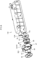
- the negative pressure pump 10 of the first embodiment is given a configuration where the drive shaft 100 is inserted from the first casing 22 of the negative pressure pump 10, but the present invention is not limited to this configuration and, like a negative pressure pump 11 of an example modification shown in FIG. 4 and FIG. 5 , may also be given a configuration where the drive shaft 100 is inserted from the second casing 32.
- the cylinder portion 24 is closed off by the jutting wall portion 28 of the first casing 22, an open portion is instead formed in the cover 39 of the second casing 32, and the drive shaft 100 is inserted from this open portion.
- the cylinder head cover 120 of the present embodiment is used to cover a cylinder head of an engine.
- the cylinder head cover 120 is equipped with the negative pressure pump 10 of the first embodiment. Furthermore, part of the cylinder head cover 120 configures (doubles as) the first casing 22 of the negative pressure pump 10.
- the cylinder head cover 120 may comprise a magnetic body or a nonmagnetic body, but in the present embodiment it is formed by resin.
- the cylinder head cover 120 is equipped with the negative pressure pump 10, the action of the thrust force on the drive shaft 100 driven to rotate by the engine can be controlled, and energy loss of the engine can be reduced by intermittently transmitting the rotation from the drive shaft 100. Because of this, the fuel economy of the engine (vehicle) can be improved.
- the cylinder head cover 120 forms the first casing 22
- manufacturing costs can be reduced compared, for example, to a configuration where the cylinder head cover 120 and the negative pressure pump 10 are separate bodies.
Landscapes
- Engineering & Computer Science (AREA)
- General Engineering & Computer Science (AREA)
- Mechanical Engineering (AREA)
- Physics & Mathematics (AREA)
- Electromagnetism (AREA)
- Combustion & Propulsion (AREA)
- Chemical & Material Sciences (AREA)
- Mechanical Operated Clutches (AREA)
- Compressors, Vaccum Pumps And Other Relevant Systems (AREA)
- Applications Or Details Of Rotary Compressors (AREA)
- Details And Applications Of Rotary Liquid Pumps (AREA)
- Rotary Pumps (AREA)
- Hydraulic Clutches, Magnetic Clutches, Fluid Clutches, And Fluid Joints (AREA)
Applications Claiming Priority (2)
| Application Number | Priority Date | Filing Date | Title |
|---|---|---|---|
| JP2013157712A JP5799058B2 (ja) | 2013-07-30 | 2013-07-30 | 負圧ポンプ及びシリンダヘッドカバー |
| PCT/JP2014/063254 WO2015015868A1 (ja) | 2013-07-30 | 2014-05-19 | 負圧ポンプ及びシリンダヘッドカバー |
Publications (3)
| Publication Number | Publication Date |
|---|---|
| EP2982864A1 EP2982864A1 (en) | 2016-02-10 |
| EP2982864A4 EP2982864A4 (en) | 2016-05-18 |
| EP2982864B1 true EP2982864B1 (en) | 2017-08-09 |
Family
ID=52431414
Family Applications (1)
| Application Number | Title | Priority Date | Filing Date |
|---|---|---|---|
| EP14831527.8A Not-in-force EP2982864B1 (en) | 2013-07-30 | 2014-05-19 | Negative pressure pump and cylinder head cover |
Country Status (5)
| Country | Link |
|---|---|
| US (1) | US10233915B2 (enExample) |
| EP (1) | EP2982864B1 (enExample) |
| JP (1) | JP5799058B2 (enExample) |
| CN (1) | CN105190032B (enExample) |
| WO (1) | WO2015015868A1 (enExample) |
Families Citing this family (7)
| Publication number | Priority date | Publication date | Assignee | Title |
|---|---|---|---|---|
| JP6549418B2 (ja) * | 2015-05-28 | 2019-07-24 | 三桜工業株式会社 | 負圧ポンプ |
| US10294454B2 (en) | 2016-08-24 | 2019-05-21 | General Electric Company | Methods and kits for cell activation |
| CN106246549B (zh) * | 2016-08-31 | 2018-11-30 | 上海肇民动力科技有限公司 | 真空泵 |
| US11529725B2 (en) * | 2017-10-20 | 2022-12-20 | Milwaukee Electric Tool Corporation | Power tool including electromagnetic clutch |
| EP3700713B1 (en) | 2017-10-26 | 2023-07-12 | Milwaukee Electric Tool Corporation | Kickback control methods for power tools |
| US11641102B2 (en) | 2020-03-10 | 2023-05-02 | Smart Wires Inc. | Modular FACTS devices with external fault current protection within the same impedance injection module |
| FR3131354B1 (fr) * | 2021-12-29 | 2024-02-09 | Valeo Embrayages | Ensemble d’actionnement et actionneur pour groupe motopropulseur |
Family Cites Families (25)
| Publication number | Priority date | Publication date | Assignee | Title |
|---|---|---|---|---|
| US2230717A (en) * | 1939-10-24 | 1941-02-04 | Gilbert & Barker Mfg Co | Pumping means |
| US4009971A (en) * | 1974-06-07 | 1977-03-01 | Binks Manufacturing Company | Electric motor-driven, double-acting pump having pressure-responsive actuation |
| US4056178A (en) * | 1976-04-28 | 1977-11-01 | Eaton Corporation | Magnetically actuated viscous fluid coupling |
| JPS5690435U (enExample) * | 1979-12-15 | 1981-07-18 | ||
| JPS5751991A (en) * | 1980-09-12 | 1982-03-27 | Seiko Seiki Co Ltd | Bearing structure for gas compressor |
| US4516918A (en) * | 1982-05-25 | 1985-05-14 | Trw Inc. | Pump assembly |
| GB2162255B (en) * | 1984-03-30 | 1988-02-03 | Grau Girling Limited | Multi-plate clutch in an air compressor |
| EP0284388A3 (en) * | 1987-03-26 | 1989-11-15 | Bendix Limited | Clutch driven compressor assembly |
| US4840543A (en) * | 1988-08-10 | 1989-06-20 | Geberth John Daniel Jun | Clutch apparatus for rapid power source conversion |
| ES2031222T3 (es) * | 1988-12-14 | 1992-12-01 | Christian Mayr Gmbh & Co. Kg | Dispositivo automatico de reajuste para grupos de embrague y/o de frenado accionados electromagneticamente. |
| JPH0872700A (ja) * | 1994-08-31 | 1996-03-19 | Nabco Ltd | 負圧発生装置 |
| US5989151A (en) * | 1998-08-11 | 1999-11-23 | Siemens Canada Limited | Hybrid engine cooling system having electric motor with electro-magnetic clutch |
| US6209700B1 (en) * | 1999-09-27 | 2001-04-03 | Tractech Inc. | Electric clutch including resilient disk biasing means |
| DE20221858U1 (de) * | 2002-12-21 | 2008-09-04 | Schaeffler Kg | Brennkraftmaschine mit einer Vorrichtung zur hydraulischen Drehwinkelverstellung ihrer Nockenwelle gegenüber ihrer Kurbelwelle sowie mit einer Vakuumpumpe für einen Servoverbraucher, insbesondere für einen Bremskraftverstärker |
| DE102006022472B3 (de) * | 2006-05-13 | 2008-02-07 | Gkn Driveline International Gmbh | Hydrostatische Kupplungsanordnung mit Zahnringmaschine |
| US8763734B2 (en) * | 2007-04-05 | 2014-07-01 | Haldex Brake Corporation | Drive through air compressor with cone clutch |
| JP5359204B2 (ja) * | 2008-11-10 | 2013-12-04 | 日産自動車株式会社 | バキュームポンプ構造 |
| JP2011220326A (ja) * | 2010-03-25 | 2011-11-04 | Aisin Seiki Co Ltd | 車両用ウォータポンプ |
| JP5447149B2 (ja) * | 2010-04-27 | 2014-03-19 | 大豊工業株式会社 | ベーンポンプ |
| US9038799B2 (en) * | 2010-10-04 | 2015-05-26 | Litens Automotive Partnership | Driven component with clutch for selective operation of component |
| JP5776172B2 (ja) * | 2010-12-09 | 2015-09-09 | スズキ株式会社 | バキュームポンプの取付構造 |
| JP5482706B2 (ja) * | 2011-03-28 | 2014-05-07 | 株式会社豊田自動織機 | 変速機付き圧縮機 |
| US9217476B2 (en) * | 2011-04-13 | 2015-12-22 | Borgwarner Inc. | Friction clutch assemblies |
| JP5716615B2 (ja) * | 2011-09-08 | 2015-05-13 | トヨタ自動車株式会社 | ウォータポンプ |
| JP5890186B2 (ja) | 2012-01-27 | 2016-03-22 | 京セラ株式会社 | 携帯端末、ロック状態制御プログラムおよびロック状態制御方法 |
-
2013
- 2013-07-30 JP JP2013157712A patent/JP5799058B2/ja not_active Expired - Fee Related
-
2014
- 2014-05-19 CN CN201480025115.4A patent/CN105190032B/zh not_active Expired - Fee Related
- 2014-05-19 US US14/888,991 patent/US10233915B2/en active Active
- 2014-05-19 WO PCT/JP2014/063254 patent/WO2015015868A1/ja not_active Ceased
- 2014-05-19 EP EP14831527.8A patent/EP2982864B1/en not_active Not-in-force
Non-Patent Citations (1)
| Title |
|---|
| None * |
Also Published As
| Publication number | Publication date |
|---|---|
| JP5799058B2 (ja) | 2015-10-21 |
| CN105190032A (zh) | 2015-12-23 |
| US10233915B2 (en) | 2019-03-19 |
| EP2982864A4 (en) | 2016-05-18 |
| CN105190032B (zh) | 2017-12-29 |
| US20160084244A1 (en) | 2016-03-24 |
| WO2015015868A1 (ja) | 2015-02-05 |
| EP2982864A1 (en) | 2016-02-10 |
| JP2015028305A (ja) | 2015-02-12 |
Similar Documents
| Publication | Publication Date | Title |
|---|---|---|
| EP2982864B1 (en) | Negative pressure pump and cylinder head cover | |
| US6935478B2 (en) | Fluid friction clutch | |
| US9303512B2 (en) | Vane pump | |
| EP3359836B1 (en) | Morning sickness valve system for viscous clutch | |
| CN106104079B (zh) | 带密封机构的车辆用无级变速器 | |
| JP2015028305A5 (enExample) | ||
| JP2018532944A (ja) | 内燃機関用冷却媒体ポンプ | |
| US10344775B2 (en) | Water pump | |
| CN104929714B (zh) | 气门正时控制器 | |
| CN112576797B (zh) | 一种电动阀 | |
| JP5256814B2 (ja) | 可変フライホイール | |
| JP6244239B2 (ja) | シール機構付き車両用無段変速機 | |
| JP5784800B1 (ja) | 負圧ポンプの駆動制御方法 | |
| CN112576801B (zh) | 一种电动阀 | |
| JP6549418B2 (ja) | 負圧ポンプ | |
| KR101896322B1 (ko) | 자동변속기용 오일공급장치 | |
| JP2013221540A (ja) | 駆動力伝達装置 | |
| JP2006242288A (ja) | カップリング装置 | |
| JP2018091390A (ja) | 摩擦係合装置 |
Legal Events
| Date | Code | Title | Description |
|---|---|---|---|
| PUAI | Public reference made under article 153(3) epc to a published international application that has entered the european phase |
Free format text: ORIGINAL CODE: 0009012 |
|
| 17P | Request for examination filed |
Effective date: 20151102 |
|
| AK | Designated contracting states |
Kind code of ref document: A1 Designated state(s): AL AT BE BG CH CY CZ DE DK EE ES FI FR GB GR HR HU IE IS IT LI LT LU LV MC MK MT NL NO PL PT RO RS SE SI SK SM TR |
|
| AX | Request for extension of the european patent |
Extension state: BA ME |
|
| A4 | Supplementary search report drawn up and despatched |
Effective date: 20160415 |
|
| RIC1 | Information provided on ipc code assigned before grant |
Ipc: F04B 35/00 20060101AFI20160411BHEP Ipc: F16D 27/11 20060101ALI20160411BHEP Ipc: F04B 37/16 20060101ALI20160411BHEP Ipc: F04C 25/02 20060101ALI20160411BHEP |
|
| DAX | Request for extension of the european patent (deleted) | ||
| GRAP | Despatch of communication of intention to grant a patent |
Free format text: ORIGINAL CODE: EPIDOSNIGR1 |
|
| STAA | Information on the status of an ep patent application or granted ep patent |
Free format text: STATUS: GRANT OF PATENT IS INTENDED |
|
| INTG | Intention to grant announced |
Effective date: 20170220 |
|
| GRAS | Grant fee paid |
Free format text: ORIGINAL CODE: EPIDOSNIGR3 |
|
| GRAA | (expected) grant |
Free format text: ORIGINAL CODE: 0009210 |
|
| STAA | Information on the status of an ep patent application or granted ep patent |
Free format text: STATUS: THE PATENT HAS BEEN GRANTED |
|
| AK | Designated contracting states |
Kind code of ref document: B1 Designated state(s): AL AT BE BG CH CY CZ DE DK EE ES FI FR GB GR HR HU IE IS IT LI LT LU LV MC MK MT NL NO PL PT RO RS SE SI SK SM TR |
|
| REG | Reference to a national code |
Ref country code: GB Ref legal event code: FG4D |
|
| REG | Reference to a national code |
Ref country code: CH Ref legal event code: EP Ref country code: AT Ref legal event code: REF Ref document number: 917170 Country of ref document: AT Kind code of ref document: T Effective date: 20170815 |
|
| REG | Reference to a national code |
Ref country code: IE Ref legal event code: FG4D |
|
| REG | Reference to a national code |
Ref country code: DE Ref legal event code: R096 Ref document number: 602014013035 Country of ref document: DE |
|
| REG | Reference to a national code |
Ref country code: NL Ref legal event code: MP Effective date: 20170809 |
|
| REG | Reference to a national code |
Ref country code: LT Ref legal event code: MG4D |
|
| REG | Reference to a national code |
Ref country code: AT Ref legal event code: MK05 Ref document number: 917170 Country of ref document: AT Kind code of ref document: T Effective date: 20170809 |
|
| PG25 | Lapsed in a contracting state [announced via postgrant information from national office to epo] |
Ref country code: NO Free format text: LAPSE BECAUSE OF FAILURE TO SUBMIT A TRANSLATION OF THE DESCRIPTION OR TO PAY THE FEE WITHIN THE PRESCRIBED TIME-LIMIT Effective date: 20171109 Ref country code: FI Free format text: LAPSE BECAUSE OF FAILURE TO SUBMIT A TRANSLATION OF THE DESCRIPTION OR TO PAY THE FEE WITHIN THE PRESCRIBED TIME-LIMIT Effective date: 20170809 Ref country code: HR Free format text: LAPSE BECAUSE OF FAILURE TO SUBMIT A TRANSLATION OF THE DESCRIPTION OR TO PAY THE FEE WITHIN THE PRESCRIBED TIME-LIMIT Effective date: 20170809 Ref country code: NL Free format text: LAPSE BECAUSE OF FAILURE TO SUBMIT A TRANSLATION OF THE DESCRIPTION OR TO PAY THE FEE WITHIN THE PRESCRIBED TIME-LIMIT Effective date: 20170809 Ref country code: SE Free format text: LAPSE BECAUSE OF FAILURE TO SUBMIT A TRANSLATION OF THE DESCRIPTION OR TO PAY THE FEE WITHIN THE PRESCRIBED TIME-LIMIT Effective date: 20170809 Ref country code: AT Free format text: LAPSE BECAUSE OF FAILURE TO SUBMIT A TRANSLATION OF THE DESCRIPTION OR TO PAY THE FEE WITHIN THE PRESCRIBED TIME-LIMIT Effective date: 20170809 Ref country code: LT Free format text: LAPSE BECAUSE OF FAILURE TO SUBMIT A TRANSLATION OF THE DESCRIPTION OR TO PAY THE FEE WITHIN THE PRESCRIBED TIME-LIMIT Effective date: 20170809 |
|
| PG25 | Lapsed in a contracting state [announced via postgrant information from national office to epo] |
Ref country code: RS Free format text: LAPSE BECAUSE OF FAILURE TO SUBMIT A TRANSLATION OF THE DESCRIPTION OR TO PAY THE FEE WITHIN THE PRESCRIBED TIME-LIMIT Effective date: 20170809 Ref country code: ES Free format text: LAPSE BECAUSE OF FAILURE TO SUBMIT A TRANSLATION OF THE DESCRIPTION OR TO PAY THE FEE WITHIN THE PRESCRIBED TIME-LIMIT Effective date: 20170809 Ref country code: IS Free format text: LAPSE BECAUSE OF FAILURE TO SUBMIT A TRANSLATION OF THE DESCRIPTION OR TO PAY THE FEE WITHIN THE PRESCRIBED TIME-LIMIT Effective date: 20171209 Ref country code: GR Free format text: LAPSE BECAUSE OF FAILURE TO SUBMIT A TRANSLATION OF THE DESCRIPTION OR TO PAY THE FEE WITHIN THE PRESCRIBED TIME-LIMIT Effective date: 20171110 Ref country code: PL Free format text: LAPSE BECAUSE OF FAILURE TO SUBMIT A TRANSLATION OF THE DESCRIPTION OR TO PAY THE FEE WITHIN THE PRESCRIBED TIME-LIMIT Effective date: 20170809 Ref country code: LV Free format text: LAPSE BECAUSE OF FAILURE TO SUBMIT A TRANSLATION OF THE DESCRIPTION OR TO PAY THE FEE WITHIN THE PRESCRIBED TIME-LIMIT Effective date: 20170809 Ref country code: BG Free format text: LAPSE BECAUSE OF FAILURE TO SUBMIT A TRANSLATION OF THE DESCRIPTION OR TO PAY THE FEE WITHIN THE PRESCRIBED TIME-LIMIT Effective date: 20171109 |
|
| PG25 | Lapsed in a contracting state [announced via postgrant information from national office to epo] |
Ref country code: DK Free format text: LAPSE BECAUSE OF FAILURE TO SUBMIT A TRANSLATION OF THE DESCRIPTION OR TO PAY THE FEE WITHIN THE PRESCRIBED TIME-LIMIT Effective date: 20170809 Ref country code: RO Free format text: LAPSE BECAUSE OF FAILURE TO SUBMIT A TRANSLATION OF THE DESCRIPTION OR TO PAY THE FEE WITHIN THE PRESCRIBED TIME-LIMIT Effective date: 20170809 Ref country code: CZ Free format text: LAPSE BECAUSE OF FAILURE TO SUBMIT A TRANSLATION OF THE DESCRIPTION OR TO PAY THE FEE WITHIN THE PRESCRIBED TIME-LIMIT Effective date: 20170809 |
|
| REG | Reference to a national code |
Ref country code: DE Ref legal event code: R097 Ref document number: 602014013035 Country of ref document: DE |
|
| PG25 | Lapsed in a contracting state [announced via postgrant information from national office to epo] |
Ref country code: SK Free format text: LAPSE BECAUSE OF FAILURE TO SUBMIT A TRANSLATION OF THE DESCRIPTION OR TO PAY THE FEE WITHIN THE PRESCRIBED TIME-LIMIT Effective date: 20170809 Ref country code: IT Free format text: LAPSE BECAUSE OF FAILURE TO SUBMIT A TRANSLATION OF THE DESCRIPTION OR TO PAY THE FEE WITHIN THE PRESCRIBED TIME-LIMIT Effective date: 20170809 Ref country code: EE Free format text: LAPSE BECAUSE OF FAILURE TO SUBMIT A TRANSLATION OF THE DESCRIPTION OR TO PAY THE FEE WITHIN THE PRESCRIBED TIME-LIMIT Effective date: 20170809 Ref country code: SM Free format text: LAPSE BECAUSE OF FAILURE TO SUBMIT A TRANSLATION OF THE DESCRIPTION OR TO PAY THE FEE WITHIN THE PRESCRIBED TIME-LIMIT Effective date: 20170809 |
|
| PLBE | No opposition filed within time limit |
Free format text: ORIGINAL CODE: 0009261 |
|
| STAA | Information on the status of an ep patent application or granted ep patent |
Free format text: STATUS: NO OPPOSITION FILED WITHIN TIME LIMIT |
|
| 26N | No opposition filed |
Effective date: 20180511 |
|
| PG25 | Lapsed in a contracting state [announced via postgrant information from national office to epo] |
Ref country code: SI Free format text: LAPSE BECAUSE OF FAILURE TO SUBMIT A TRANSLATION OF THE DESCRIPTION OR TO PAY THE FEE WITHIN THE PRESCRIBED TIME-LIMIT Effective date: 20170809 |
|
| REG | Reference to a national code |
Ref country code: CH Ref legal event code: PL |
|
| GBPC | Gb: european patent ceased through non-payment of renewal fee |
Effective date: 20180519 |
|
| REG | Reference to a national code |
Ref country code: BE Ref legal event code: MM Effective date: 20180531 |
|
| PG25 | Lapsed in a contracting state [announced via postgrant information from national office to epo] |
Ref country code: MC Free format text: LAPSE BECAUSE OF FAILURE TO SUBMIT A TRANSLATION OF THE DESCRIPTION OR TO PAY THE FEE WITHIN THE PRESCRIBED TIME-LIMIT Effective date: 20170809 |
|
| REG | Reference to a national code |
Ref country code: IE Ref legal event code: MM4A |
|
| PG25 | Lapsed in a contracting state [announced via postgrant information from national office to epo] |
Ref country code: LI Free format text: LAPSE BECAUSE OF NON-PAYMENT OF DUE FEES Effective date: 20180531 Ref country code: CH Free format text: LAPSE BECAUSE OF NON-PAYMENT OF DUE FEES Effective date: 20180531 |
|
| PG25 | Lapsed in a contracting state [announced via postgrant information from national office to epo] |
Ref country code: LU Free format text: LAPSE BECAUSE OF NON-PAYMENT OF DUE FEES Effective date: 20180519 |
|
| PG25 | Lapsed in a contracting state [announced via postgrant information from national office to epo] |
Ref country code: GB Free format text: LAPSE BECAUSE OF NON-PAYMENT OF DUE FEES Effective date: 20180519 Ref country code: FR Free format text: LAPSE BECAUSE OF NON-PAYMENT OF DUE FEES Effective date: 20180531 Ref country code: IE Free format text: LAPSE BECAUSE OF NON-PAYMENT OF DUE FEES Effective date: 20180519 |
|
| PG25 | Lapsed in a contracting state [announced via postgrant information from national office to epo] |
Ref country code: BE Free format text: LAPSE BECAUSE OF NON-PAYMENT OF DUE FEES Effective date: 20180531 |
|
| PG25 | Lapsed in a contracting state [announced via postgrant information from national office to epo] |
Ref country code: MT Free format text: LAPSE BECAUSE OF NON-PAYMENT OF DUE FEES Effective date: 20180519 |
|
| PG25 | Lapsed in a contracting state [announced via postgrant information from national office to epo] |
Ref country code: TR Free format text: LAPSE BECAUSE OF FAILURE TO SUBMIT A TRANSLATION OF THE DESCRIPTION OR TO PAY THE FEE WITHIN THE PRESCRIBED TIME-LIMIT Effective date: 20170809 |
|
| PG25 | Lapsed in a contracting state [announced via postgrant information from national office to epo] |
Ref country code: PT Free format text: LAPSE BECAUSE OF FAILURE TO SUBMIT A TRANSLATION OF THE DESCRIPTION OR TO PAY THE FEE WITHIN THE PRESCRIBED TIME-LIMIT Effective date: 20170809 |
|
| PG25 | Lapsed in a contracting state [announced via postgrant information from national office to epo] |
Ref country code: MK Free format text: LAPSE BECAUSE OF NON-PAYMENT OF DUE FEES Effective date: 20170809 Ref country code: CY Free format text: LAPSE BECAUSE OF FAILURE TO SUBMIT A TRANSLATION OF THE DESCRIPTION OR TO PAY THE FEE WITHIN THE PRESCRIBED TIME-LIMIT Effective date: 20170809 Ref country code: HU Free format text: LAPSE BECAUSE OF FAILURE TO SUBMIT A TRANSLATION OF THE DESCRIPTION OR TO PAY THE FEE WITHIN THE PRESCRIBED TIME-LIMIT; INVALID AB INITIO Effective date: 20140519 |
|
| PG25 | Lapsed in a contracting state [announced via postgrant information from national office to epo] |
Ref country code: AL Free format text: LAPSE BECAUSE OF FAILURE TO SUBMIT A TRANSLATION OF THE DESCRIPTION OR TO PAY THE FEE WITHIN THE PRESCRIBED TIME-LIMIT Effective date: 20170809 |
|
| PGFP | Annual fee paid to national office [announced via postgrant information from national office to epo] |
Ref country code: DE Payment date: 20220329 Year of fee payment: 9 |
|
| REG | Reference to a national code |
Ref country code: DE Ref legal event code: R119 Ref document number: 602014013035 Country of ref document: DE |
|
| PG25 | Lapsed in a contracting state [announced via postgrant information from national office to epo] |
Ref country code: DE Free format text: LAPSE BECAUSE OF NON-PAYMENT OF DUE FEES Effective date: 20231201 |