WO2015012350A1 - 立軸ポンプ - Google Patents
立軸ポンプ Download PDFInfo
- Publication number
- WO2015012350A1 WO2015012350A1 PCT/JP2014/069555 JP2014069555W WO2015012350A1 WO 2015012350 A1 WO2015012350 A1 WO 2015012350A1 JP 2014069555 W JP2014069555 W JP 2014069555W WO 2015012350 A1 WO2015012350 A1 WO 2015012350A1
- Authority
- WO
- WIPO (PCT)
- Prior art keywords
- bearing
- vertical shaft
- sliding
- shaft pump
- sleeve
- Prior art date
- Legal status (The legal status is an assumption and is not a legal conclusion. Google has not performed a legal analysis and makes no representation as to the accuracy of the status listed.)
- Ceased
Links
Images










Classifications
-
- F—MECHANICAL ENGINEERING; LIGHTING; HEATING; WEAPONS; BLASTING
- F04—POSITIVE - DISPLACEMENT MACHINES FOR LIQUIDS; PUMPS FOR LIQUIDS OR ELASTIC FLUIDS
- F04D—NON-POSITIVE-DISPLACEMENT PUMPS
- F04D13/00—Pumping installations or systems
- F04D13/02—Units comprising pumps and their driving means
- F04D13/06—Units comprising pumps and their driving means the pump being electrically driven
- F04D13/08—Units comprising pumps and their driving means the pump being electrically driven for submerged use
-
- F—MECHANICAL ENGINEERING; LIGHTING; HEATING; WEAPONS; BLASTING
- F04—POSITIVE - DISPLACEMENT MACHINES FOR LIQUIDS; PUMPS FOR LIQUIDS OR ELASTIC FLUIDS
- F04D—NON-POSITIVE-DISPLACEMENT PUMPS
- F04D29/00—Details, component parts, or accessories
- F04D29/04—Shafts or bearings, or assemblies thereof
- F04D29/046—Bearings
- F04D29/0465—Ceramic bearing designs
-
- F—MECHANICAL ENGINEERING; LIGHTING; HEATING; WEAPONS; BLASTING
- F04—POSITIVE - DISPLACEMENT MACHINES FOR LIQUIDS; PUMPS FOR LIQUIDS OR ELASTIC FLUIDS
- F04D—NON-POSITIVE-DISPLACEMENT PUMPS
- F04D29/00—Details, component parts, or accessories
- F04D29/04—Shafts or bearings, or assemblies thereof
- F04D29/046—Bearings
- F04D29/047—Bearings hydrostatic; hydrodynamic
- F04D29/0476—Bearings hydrostatic; hydrodynamic for axial pumps
-
- F—MECHANICAL ENGINEERING; LIGHTING; HEATING; WEAPONS; BLASTING
- F16—ENGINEERING ELEMENTS AND UNITS; GENERAL MEASURES FOR PRODUCING AND MAINTAINING EFFECTIVE FUNCTIONING OF MACHINES OR INSTALLATIONS; THERMAL INSULATION IN GENERAL
- F16C—SHAFTS; FLEXIBLE SHAFTS; ELEMENTS OR CRANKSHAFT MECHANISMS; ROTARY BODIES OTHER THAN GEARING ELEMENTS; BEARINGS
- F16C17/00—Sliding-contact bearings for exclusively rotary movement
- F16C17/02—Sliding-contact bearings for exclusively rotary movement for radial load only
-
- F—MECHANICAL ENGINEERING; LIGHTING; HEATING; WEAPONS; BLASTING
- F16—ENGINEERING ELEMENTS AND UNITS; GENERAL MEASURES FOR PRODUCING AND MAINTAINING EFFECTIVE FUNCTIONING OF MACHINES OR INSTALLATIONS; THERMAL INSULATION IN GENERAL
- F16C—SHAFTS; FLEXIBLE SHAFTS; ELEMENTS OR CRANKSHAFT MECHANISMS; ROTARY BODIES OTHER THAN GEARING ELEMENTS; BEARINGS
- F16C27/00—Elastic or yielding bearings or bearing supports, for exclusively rotary movement
- F16C27/02—Sliding-contact bearings
Definitions
- the present invention relates to a vertical shaft pump having a sliding bearing, and more particularly to a vertical shaft pump that performs an operation in the atmosphere and a drainage (water flow) operation such as a prior standby operation pump or a pump that performs a management operation under dry conditions.
- drainage pumps installed in the drainage pump station will prevent rainwater from reaching the drainage pump station in order to prevent inundation damage due to delays in starting.
- a pre-standby operation that is started in advance is performed.
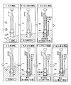
- FIG. 1 is a partial schematic diagram of a vertical shaft pump that performs a preliminary standby operation.
- the water tank 100 of the drainage station is provided with an impeller 22 at the end of a shaft arranged in the vertical direction, and the impeller 22 is inhaled with air to operate even if the water level of the water tank 100 is below the minimum operating water level LWL.
- a vertical shaft pump 3 capable of continuing (preceding standby operation) is disposed.
- This vertical shaft pump 3 is provided with a through hole 5 in the side surface portion of the suction bell 27 on the inlet side of the impeller 22, and an air pipe 6 having an opening 6 a in contact with outside air is attached to the through hole 5. Yes.
- the supply amount of the air supplied into the vertical shaft pump 3 through the through hole 5 is changed according to the water level, and the drainage amount of the vertical pump 3 is controlled below the minimum operating water level LWL.
- FIG. 2 is a diagram for explaining the operating state of the preceding standby operation.
- a vertical shaft pump is started in advance based on rainfall information or the like regardless of the suction water level (A: air operation).
- A air operation
- the vertical shaft pump operates from the idle operation (air operation) to the water agitating with the impeller (B: air / water agitation operation), and from the through hole.
- D steady operation
- C air-water mixing operation
- FIG. 3 is a cross-sectional view showing the entire vertical shaft pump 3 that performs the preliminary standby operation shown in FIG. The through hole 5 and the air pipe 6 shown in FIG. 2 are not shown.
- the vertical shaft pump 3 is connected to the discharge elbow 30 that is installed and fixed on the pump installation floor, the casing 29 that is connected to the lower end of the discharge elbow 30, and the lower end of the casing 29.
- a discharge bowl 28 stored inside, and a suction bell 27 connected to the lower end of the discharge bowl 28 for sucking water are provided.
- Rotating shafts 10, 10 ′ connected to each other by a shaft coupling 26 are disposed in the radial center of the casing 29, the discharge bowl 28, and the suction bell 27 of the vertical shaft pump 3.
- the rotary shafts 10 and 10 ' are supported by an upper bearing 32 fixed to the casing 29 via a support member and a lower bearing 33 fixed to the discharge bowl 28 via a support member.
- An impeller 22 for sucking water into the pump is connected to one end side (suction bell 27 side) of the rotary shafts 10 and 10 '.
- the other end side of the rotary shafts 10 and 10 ′ is connected to a driving machine such as an engine or a motor (not shown) that rotates the impeller 22 through the hole provided in the discharge elbow 30 to the outside of the vertical shaft pump 3.
- a shaft seal 34 such as a floating seal, a gland packing, or a mechanical seal is provided between the rotary shafts 10 and 10 'and a hole provided in the discharge elbow 30, and thereby water handled by the vertical pump 3 is supplied to the vertical pump. 3 is prevented from flowing out.
- the drive will be installed on land so that maintenance and inspection can be performed easily.
- the rotation of the driving machine is transmitted to the rotating shafts 10, 10 ', and the impeller 22 can be rotated.
- the water is sucked from the suction bell 27 by the rotation of the impeller 22, passes through the discharge bowl 28 and the casing 29, and is discharged from the discharge elbow 30.
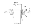
- FIG. 4 is an enlarged view of a conventional bearing device applied to the bearings 32 and 33 shown in FIG. 3, and FIG. 5 is a perspective view of the plain bearing.
- the conventional bearing device has a metal sleeve 11 made of stainless steel or the like on the outer periphery of the rotary shaft 10 (10 ′).
- a slide bearing 1 shown in FIG. 5 made of a hollow cylindrical resin material, ceramics, sintered metal, or surface-modified metal is provided.
- the outer peripheral surface of the sleeve 11 faces the inner peripheral surface (slide surface) of the slide bearing 1 through a very narrow clearance, and is configured to slide with respect to the slide bearing 1.
- the slide bearing 1 is fixed to a support member 13 connected to a pump casing 29 (see FIG. 3) or the like via a collar portion 12a by a bearing case 12 made of metal or resin.
- the vertical shaft pump 3 shown in FIG. 3 is operated in the atmosphere when the pump is started. That is, the bearings 32 and 33 are operated under dry conditions without lubrication with liquid.
- the dry condition refers to a condition in which the atmosphere of the bearings 32 and 33 during the pump operation is in the air without lubrication by the liquid
- the dry operation refers to operation under that condition.
- the bearings 32 and 33 shown in FIG. 3 are also operated under drainage conditions in which water has passed through the bearings.
- the drainage condition refers to a condition in which the atmosphere of the bearings 32 and 33 during operation of the pump is in water mixed with foreign matter (slurry) such as earth and sand. It refers to water-mixing operation, full-volume operation, air lock operation, etc. Since the bearings 32 and 33 are used under such conditions, the bearings 32 and 33 have the following problems.
- the slide bearing 1 In the case of the vertical shaft pump 3 that performs dry operation, a resin or ceramic bearing is used from the viewpoint of dry sliding performance and reliability during drainage operation. There are many. In this case, the slide bearing 1 is required to withstand frictional heat generation during the dry operation and to be resistant to abrasion due to the slurry in the water during the drain operation. However, these two characteristics often contradict each other, and bearing materials with high wear resistance generally tend to have a high friction coefficient. For this reason, if bearing materials are selected giving priority to wear resistance during drainage operation, frictional heat generation under dry conditions will increase, and if bearing materials with a low friction coefficient are selected to suppress frictional heat generation under dry conditions, The wear amount of the bearing material due to the slurry during operation increases.
- the friction coefficient of the bearing sliding surface increases.
- the friction described below may occur due to the friction of the bearing sliding surface.
- the rotating machine when a rotating machine such as the vertical shaft pump 3 is operated, the rotating machine may vibrate due to an unbalanced weight of the rotating body itself or an excitation force that is forcedly generated in the rotating body due to a fluid load.
- a cause of vibration of the rotating machine there is a force generated in a direction (circumferential direction of the rotating body) perpendicular to the displacement direction (radial direction of the rotating body) due to the swing of the rotating body.
- This force is called destabilizing force and has the function of canceling the damping action of the rotating body.
- divergent vibration (vibration that gradually increases the swinging) may be caused.
- the bearing sliding surface has a larger coefficient of friction. Since this frictional force becomes the above destabilizing force, when a bearing material having a high friction coefficient is used, the destabilizing force becomes large and the rotating shafts 10 and 10 'are divergently swung in the direction opposite to the rotational direction. Will cause excessive vibration. Further, when such divergent vibration occurs during dry operation, the bearing surface pressure increases due to the vibration, and the frictional force generated on the bearing sliding surface becomes extremely large. Therefore, there is a possibility that the bearing will malfunction due to thermal expansion or seizure due to a sudden rise in bearing temperature.
- a liquid film is formed on the sliding surface of the sliding bearing 1 during the drainage operation of the vertical shaft pump 3.
- This liquid film generates a destabilizing force, which may cause a large vibration.
- This phenomenon occurs in a mechanism similar to a phenomenon called oil whip or oil whirl in a sliding bearing lubricated with oil. When this phenomenon occurs, the rotary shafts 10 and 10 'vibrate violently and normal operation is impossible.
- a slide bearing for a vertical shaft pump that performs a preliminary standby operation requires performances such as wear resistance, heat generation resistance (low friction property), and vibration resistance. These requirements are simultaneously satisfied at a high level. It has been difficult so far. Also, bearing materials with high wear resistance often cannot be used due to their high friction coefficient under dry conditions, resulting in a problem that the bearing life cannot be greatly improved.
- the vertical shaft pump 3 requires more bearings depending on the lengths of the rotary shafts 10 and 10 '. In this case, since all the bearings are affected by the occurrence of the vibration and wear progresses, it is necessary to replace all the bearings with a short maintenance span.
- the present invention has been made in view of the above-described conventional problems, and one of the purposes thereof is friction force and liquid film even during dry operation or drainage operation including slurry without sacrificing wear resistance. This is to reduce vibration due to destabilizing force.
- one of the other purposes is to reduce the frictional force applied to the bearing sliding surface.
- Still another object is to provide an effective means for reducing the overall wear of all the plain bearings provided in the vertical shaft pump and extending the entire life.
- a vertical shaft pump has a first sliding portion on an outer peripheral surface and a second sliding portion on an inner peripheral surface, and is in water and in the atmosphere.
- the first sliding bearing is configured to be able to support the first sliding portion in a dry condition and a drainage condition
- the second sliding bearing has a dry condition and It is configured to be able to support the second sliding portion under drainage conditions.
- the dimension of the diameter gap between the first sliding portion and the first slide bearing is 1/1000 or more of the inner diameter of the first slide bearing, and 1/100.
- the dimension of the diameter gap between the second sliding portion and the second sliding bearing is 1/1000 or more and 1/100 or less of the outer diameter of the second sliding bearing.
- the dimension of the diameter gap between the first sliding part and the first sliding bearing refers to the difference between the inner diameter of the first sliding bearing and the outer diameter of the first sliding part.
- the dimension of the diameter gap between the second sliding portion and the second sliding bearing refers to the difference between the inner diameter of the second sliding portion and the outer diameter of the second sliding bearing.
- the diameter of the second sliding portion and the second sliding bearing with respect to the size of the diameter gap between the first sliding portion and the first sliding bearing is 0.5 or more and 2.0 or less.
- the diameter of the second sliding portion and the second sliding bearing with respect to the size of the diameter gap between the first sliding portion and the first sliding bearing.
- the ratio of the dimension of the gap is 0.7 or more and 1.3 or less.
- the ratio of the outer diameter of the second sliding bearing to the inner diameter of the first sliding bearing is 0.2 or more and 2.0 or less.
- the portion of the rotating member located in the water is supported only by the slide bearing.
- the plain bearing is PA, PBI, POM, PBT, PET, PPE, PC, UHMW-PE, PTFE, PPS, PI, PEEK, PAR, PSF, PEI, PAI. , PES, and resin material including at least one of PF, ceramics, or metal.
- the sliding bearing includes a resin material to which at least one of carbon fiber, glass fiber, carbon particle, glass particle, and graphite is added.
- water is supplied to the gap between the first sliding portion and the first slide bearing and the gap between the second sliding portion and the second slide bearing.
- a flow path through which the gas passes is formed.
- the vertical shaft pump according to another embodiment of the present invention is configured to be installed in the drainage station.
- a vertical shaft pump includes a strainer at a water supply port for passing water through the flow path.
- a vertical shaft pump includes a bearing case that holds the sliding bearing, the bearing case holding the first sliding bearing on an inner circumferential surface thereof, and the second sliding shaft on an outer circumferential surface thereof. Hold the slide bearing.
- the rotating member is a rotating shaft
- the second sliding portion is provided at an end of the rotating shaft.
- the first sliding bearing and / or the second sliding bearing is divided in the circumferential direction.
- a vertical shaft pump is a vertical shaft pump including a plurality of bearing devices, and at least one of the bearing devices includes the first slide bearing and the second slide bearing.
- the present invention it is possible to reduce vibration due to frictional force or destabilizing force due to a liquid film or the like during dry operation or drainage operation including slurry without sacrificing wear resistance. Further, according to the present invention, the frictional force applied to the bearing sliding surface can be reduced, and as a result, the amount of heat generated by the sliding bearing can be reduced, so that a bearing material with a higher friction coefficient, that is, a bearing with higher wear resistance Material can be used.
- the vertical shaft pump provided with a plurality of slide bearings has a configuration in which at least one set of the slide bearings is a combination of the first slide bearing and the second slide bearing, whereby the slide provided for the vertical pump is provided. It is possible to provide an effective means for reducing overall bearing wear and extending overall life.
- FIG. 1 It is a partial schematic diagram of a vertical shaft pump that performs a preliminary standby operation. It is a figure explaining the driving
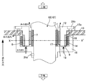
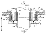
- FIG. 6 is a longitudinal sectional view of a bearing device applied to the vertical shaft pump according to the present embodiment.
- the vertical pump according to the present embodiment applies the bearing device shown in FIG. 6 instead of the bearings 32 and 33 of the vertical pump 3 that performs the preliminary standby operation shown in FIG. Since the configuration is the same as that of the vertical pump 3 shown in FIG. 3, the description of the entire vertical pump 3 according to this embodiment is omitted.
- This bearing device has a metal sleeve 11 made of cemented carbide or stainless steel on the outer periphery of the rotary shaft 10 (10 ').
- a first plain bearing 1 made of a hollow cylindrical resin material, ceramics, sintered metal or surface-modified metal shown in FIG. 5.
- the outer peripheral surface (first sliding portion 17) of the sleeve 11 faces the inner peripheral surface (sliding surface) of the first slide bearing 1 via a very narrow first clearance 7, and the first slide bearing. It is configured to slide against one sliding surface.
- the outer peripheral portion of the first plain bearing 1 is fixed to the inner peripheral surface of a bearing case 12 made of metal or resin, and the bearing case 12 is connected to the casing 29 (see FIG. 3) of the vertical shaft pump 3 via a collar portion 12a. ) And the like are fixed to the supporting member 13 by fixing means 21b such as bolts.
- a second sliding bearing 9 made of a hollow cylindrical resin material, ceramics, sintered metal, or surface-modified metal is provided on the outer peripheral surface of the first bearing case 12.
- a sleeve case 15 is fixed to the rotating shaft 10 (10 ') by fixing means 21a such as a fixing pin or a bolt.
- the sleeve case 15 is configured to rotate in the same manner as the rotation shaft 10 (10 ′) when the rotation shaft 10 (10 ′) rotates.
- a sleeve 14 is provided on the inner peripheral surface of the sleeve case 15.
- the inner peripheral surface (second sliding portion 18) of the sleeve 14 faces the outer peripheral surface (sliding surface) of the second slide bearing 9 via a very narrow second clearance 8, and the second slide bearing 9 It is comprised so that it may slide with respect to the sliding surface.
- the sleeve case 15 is provided with a water supply port 19 through which water containing slurry or the like passes through the first clearance 7 and the second clearance 8.
- the water that has flowed into the water supply port 19 passes through the first clearance 7 and the second clearance 8 as flow paths.
- a flow path for allowing water to pass through the first clearance 7 and the second clearance 8 is formed, and the first clearance 7 and the second clearance 8 also function as a flow path. Water can flow promptly through the first clearance 7 and the second clearance 8 without staying, and the functions of the first slide bearing 1 and the second slide bearing 9 can be exhibited quickly.
- the first slide bearing 1 and the second slide bearing 9 support the sleeve 11 and the sleeve 14 under dry conditions when the vertical shaft pump 3 is started, and the sleeve 11 and sleeve through a very thin liquid film under drainage conditions. 14 is supported.
- the diameter of the first clearance 7 is used to suppress the steady swing of the rotary shaft 10 (10 ') and to suppress the load applied to the first slide bearing 1 and the second slide bearing 9 due to the swing.
- the clearance dimension (the inner diameter of the first sliding bearing 1 ⁇ the outer diameter of the sleeve 11) and the diameter clearance dimension of the second clearance 8 (the inner diameter of the sleeve 14 ⁇ the outer diameter of the second sliding bearing 9) are respectively It is preferable that it is 1/1000 or more and 1/100 or less of the inner diameter of the slide bearing 1 and 1/1000 or more and 1/100 or less of the outer diameter of the second slide bearing 9.
- the first clearance 7 and the second clearance 8 are larger than these ranges, the steady swing of the rotary shaft 10 (10 ′) becomes large, and the swing of the first slide bearing 1 and the second clearance 8 increases.
- the load applied to the second plain bearing 9 also increases, and stable operation may be difficult.
- the first clearance 7 and the second clearance 8 are smaller than these ranges, the first clearance 7 and the second clearance 8 are blocked by foreign matter, or the first slide bearing 1 and the second clearance 8 are closed. 2 may be seized due to friction with foreign matter.
- the diameter clearance dimension of the first clearance 7 and the diameter clearance dimension of the second clearance 8 are preferably the same, but the first sliding bearing 1, the second sliding bearing 9, the sleeve 14, or the sleeve 11 is made of resin. If these members have elasticity, such as being formed of, the function of the present invention is exhibited even if there is a difference in dimensions.
- the ratio of the diameter clearance dimension of the second clearance 8 to the diameter clearance dimension of the first clearance 7 is preferably 0.5 or more and 2.0 or less, more preferably 0.7 or more and 1.3. It is as follows.
- the cushioning is performed.
- the first slide bearing 1 and the second slide bearing 9 can be in contact with the sleeve 11 and the sleeve 14 at the same time, even if they are not in the above-mentioned range due to the deformation of the material, and the function of the present invention is exhibited.
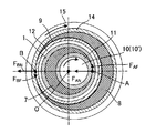
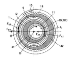
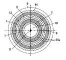
- FIG. 7 is a cross-sectional view taken along the line XX ′ shown in FIG. As shown in the drawing, the centers of the outer peripheral surface of the sleeve 11, the inner peripheral surface of the first slide bearing 1, the outer peripheral surface of the second slide bearing 9, and the inner peripheral surface of the sleeve 14 are substantially coincident with the central axis O. Is configured to do. In FIG. 7, the dimensions of the first clearance 7 and the second clearance 9 are shown enlarged for convenience.
- FIG. 8 is a diagram illustrating the operation of the bearing device during the dry operation.
- the rotating shaft 10 (10 ′) rotates
- the sleeve 11 fixed to the rotating shaft 10 (10 ′) and the sleeve 14 fixed to the sleeve case 15 also rotate.
- a bearing reaction force FAN is generated on the rotary shaft 10 (10 ′).
- This bearing reaction force F AN, frictional force F AF is generated in a direction opposite to the rotating direction of the rotary shaft 10 (10 '), opposite the friction force F AF is the rotational direction in the rotation shaft 10 (10') It becomes a destabilizing force that causes a whirling vibration in the direction.
- FIG. 9 is a diagram illustrating the operation of the bearing device during the drain operation.
- the first clearance 7 and the second clearance 8 are filled with water, and the water constitutes a liquid film 41 and a liquid film 42, respectively, whereby the present bearing device functions as a fluid lubrication bearing device.
- a circumferential pressure non-uniformity occurs in the liquid film 41 due to the rotation of the rotating shaft 10 (10 ′).
- the radial fluid force F AR and the circumferential fluid force F AT are applied to the rotating shaft 10 (10 ′). Will occur.
- the circumferential fluid force F AT becomes destabilizing force that generates vibrations during drainage operation.
- the circumferential fluid force F AT is the frictional force F AF generated by the drying operation is a reverse force.
- the inner surface of the bearing has been formed into a multi-arc shape instead of a perfect circle shape.
- the inner surface shape of the bearing approaches a perfect circle shape due to wear, and the vibration suppressing effect may be lost.
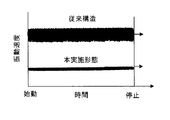
- FIG. 10 is a diagram showing a vibration speed when the vertical shaft pump 3 according to the present embodiment including the bearing device shown in FIG. 6 is dry-operated.
- the vibration speed when the vertical shaft pump (conventional structure) including the conventional bearing device shown in FIG. Note that both the conventional bearing device and the bearing device shown in FIG. 6 use the same material having high wear resistance and a high friction coefficient as a slide bearing.
- the vertical shaft pump 3 (this embodiment) provided with the bearing device is operated at a lower vibration speed than the conventional structure in a constant manner from the start to the stop.
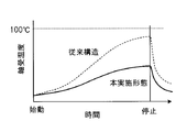
- FIG. 11 is a diagram showing the bearing temperature when the vertical shaft pump 3 according to the present embodiment including the bearing device shown in FIG. 6 is dry-operated.
- the bearing temperature when the vertical shaft pump (conventional structure) including the conventional bearing device shown in FIG. Note that both the conventional bearing device and the bearing device shown in FIG. 6 use the same material having high wear resistance and a high friction coefficient as a slide bearing.
- the bearing temperature is kept constant from the start to the stop as compared with the conventional structure.
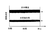
- FIG. 12 is a diagram showing the vibration speed when the vertical shaft pump 3 according to the present embodiment including the bearing device shown in FIG. 6 performs the drainage operation.
- the vibration speed when the vertical pump (conventional structure) including the conventional bearing device shown in FIG. 12 measured the vibration at the time of driving
- the vertical shaft pump 3 (this embodiment) provided with the bearing device is operated at a lower vibration speed than the conventional structure in a constant manner from the start to the stop.
- the first slide bearing 1 and the second slide bearing 9 are caused by the swing of the shaft of the rotary shaft 10 (10 ′) during the dry operation. Even if the rotating bodies (sleeve 11 and sleeve 14) collide with each other, the direction of the frictional force acts in the opposite directions to cancel each other at the time of the collision, thereby suppressing the divergence of the rotating shaft 10 (10 '). Vibration due to destabilization can be prevented. In addition, it is possible to reduce friction caused by this vibration and suppress an increase in bearing temperature.
- the vertical shaft pump 3 since the vertical shaft pump 3 according to the present embodiment includes the first slide bearing 1 and the second slide bearing 9, the frictional force of the bearing slide surface during the dry operation is dispersed to suppress heat generation due to the friction of the bearing slide surface. can do. Thereby, a bearing material having a higher friction coefficient than that of the conventional structure, that is, a bearing material having higher wear resistance can be used, and stable operation can be performed for a long period of time.
- the first slide bearing 1 is held on the inner peripheral surface of the bearing case 12 and the second slide bearing 9 is held on the outer peripheral surface thereof.
- the structure can be made compact in the direction.
- the portions (the sleeve 11 and the sleeve 14) located in the water of the rotary shaft 10 (10 ′) are supported only by the sliding bearings such as the first sliding bearing 1 and the second sliding bearing 9. Is called. That is, a rolling bearing such as a ball bearing or a roller bearing is not suitable for a rotary machine that performs drainage operation such as the vertical shaft pump 3, and the effect of the present embodiment can be achieved by a sliding bearing.
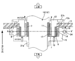
- FIG. 13 is a longitudinal sectional view of a bearing device applied to a vertical shaft pump according to another embodiment.
- a cushioning material 20a such as rubber and a cushioning material 20b are disposed on the back side (outer peripheral side) of the first slide bearing 1 and on the rear side (outer peripheral side) of the sleeve 14.
- the cushioning material 20a and the cushioning material 20b even if a material that is vulnerable to impact, such as silicon nitride or silicon carbide, is used for the first slide bearing 1 and the sleeve 14, damage due to impact during operation can be prevented. it can.
- the cushioning material 20a and / or the cushioning material 20b are deformed, so that the first sliding bearing 1 and The second sliding bearing 9 can simultaneously contact the sleeve 11 and the sleeve 14 at the same time, and the above-described destabilizing force canceling effect can be sufficiently obtained.
- shock absorbing material 20a and the shock absorbing material 20b are arrange
- the buffer material 20a and the buffer material 20b can be provided in the back surface side of the 2nd slide bearing 9. FIG.
- FIG. 14 is a longitudinal sectional view of a bearing device applied to a vertical shaft pump according to another embodiment.
- a metal back metal 31a is arranged on the back side (outer peripheral side) of the first sliding bearing 1 made of a resin material, and on the back side (outer peripheral side) of the back metal 31a.
- a buffer material 20a is arranged.
- a metal back metal 31b is disposed on the back side (outer peripheral side) of the sleeve 14, and a cushioning material 20b is disposed on the back side (outer peripheral side) of the back metal 31b.
- the back metal 31a and the back metal 31b are arrange
- the back metal 31a and the back metal 31b can be provided together with the buffer material 20a and the buffer material 20b.
- FIG. 15 is a longitudinal sectional view of a bearing device applied to a vertical shaft pump according to another embodiment.
- a metal material such as cemented carbide or stainless steel is used as the material of the second sliding bearing 9
- a resin material is used as the material of the sleeve 14.
- FIG. 16 is a longitudinal sectional view of a bearing device applied to a vertical shaft pump according to another embodiment.
- the components are arranged so as to be opposite in the axial direction of the rotary shaft 10 (10 ′). Even with such a structure, the same effect as the bearing device shown in FIG. 6 can be obtained.
- FIG. 17 is a longitudinal sectional view of a bearing device applied to a vertical shaft pump according to another embodiment
- FIG. 18 is a sectional view in the XX ′ section shown in FIG.
- the vertical shaft pump 3 is required to easily perform maintenance such as inspection and replacement of consumable parts while being installed in the drainage station. Further, at the time of assembly, depending on the shape of the vertical shaft pump 3, the sleeve case 15 and the sleeve 14 are fixed to the rotating shaft 10 (10 ') after passing the rotating shaft 10 (10') through the inside of the first slide bearing 1. There is a need to.
- the sleeve case 15 and the sleeve 14 are divided into two parts, and the divided sleeve case 15 is coupled to each other by a fixing bolt 24, so 10 (10 ′) can be fixed.
- FIG. 19 is a longitudinal sectional view of a bearing device applied to a vertical shaft pump according to another embodiment.
- a strainer 23 having an opening (mesh width) smaller than the size of the first clearance 7 and the size of the second clearance 8 is provided in the water supply port 19.
- a slurry such as earth and sand
- the diameter of the slurry contained in the water passing through the first clearance 7 and the second clearance 8 becomes sufficiently small, and wear of the sliding surface of the first sliding bearing 1 and the sliding surface of the second sliding bearing 9 occurs.
- the opening diameter of the strainer 23 is preferably less than half of the dimensions of the first clearance 7 and the second clearance 8.
- the water supply port 19 is provided in the sleeve case 15 at equal intervals along the circumference centering on the central axis of the rotating shaft 10 (10 ').
- FIG. 20 is a cross-sectional view of a bearing device applied to a vertical shaft pump according to another embodiment.
- a plurality of grooves 35 a are formed along the axial direction on the inner peripheral surface (slip surface) of the first slide bearing 1 and on the outer peripheral surface (slip surface) of the second slide bearing 9.
- the difference in curvature between the sleeve 11 and the inner peripheral surface (slide surface) of the first slide bearing 1 and the difference in curvature between the sliding surface of the sleeve 14 and the outer peripheral surface (slide surface) of the second slide bearing 9 are as follows.
- the groove 35a Since it is extremely small, even if the groove 35a is formed in this way, the influence on the contact state between the first slide bearing 1 and the sleeve 11 and the contact state between the second slide bearing 9 and the sleeve 14 is small. The same effect as the bearing device shown in FIG. Further, by forming the groove 35a in this way, the flow rate of water passing through the first clearance 7 and the second clearance 8 can be increased.
- the groove 35a may be formed only in one of the first slide bearing 1 and the second slide bearing 9. Further, the groove 35a may be provided on the sleeve side. The groove 35a may be formed not only in the axial direction of the rotating shaft 10 (10 ') but also in the circumferential direction, an oblique direction with respect to the axial direction, or one or a plurality of threads.
- FIG. 21 is a cross-sectional view of a bearing device applied to a vertical shaft pump according to another embodiment.
- the first slide bearing 1 and the second slide bearing 9 are divided into a plurality of parts in the circumferential direction, and are arranged on the inner peripheral surface of the sleeve case 15 via a gap 35b. Even with such a bearing device, the same effect as the bearing device shown in FIG. 6 can be obtained.
- first slide bearing 1 and the second slide bearing 9 may be divided and formed.
- the gap 35b may be provided on the sleeve side, that is, the sleeve 11 and / or the sleeve 14 may be divided.
- the arrangement of the second sliding bearing 9 on the rotating shaft 10 (10 ′) is not limited, and the liquid contact portion on the rotating shaft 10 (10 ′). That is, the effect of the present invention can be obtained regardless of where it is provided within the vertical shaft pump.
- the second slide bearing 9 is disposed outside the vertical pump (on the drive side), for example, in a structure that comes into contact with water even when pumping, not in the vertical pump, and the vertical pump is connected during drainage operation by connecting the interior of the vertical pump and piping. If the structure is lubricated by the discharged water, the effects of the present invention are similarly obtained.
- FIGS. 17 and 19 have been described as being applied.
- the present invention is not limited to this, and instead of any one of the bearing 32 and the bearing 33, these bearing devices may be applied.
- the vertical shaft pump 3 includes at least one of these bearing devices, the swing of the rotary shaft 10 (10 ′) can be remarkably reduced. As a result, the vibration applied to all the bearings is reduced, the wear of the bearings is reduced, the life of all the bearings can be extended as a whole, and the maintenance span can be increased.
- the number of bearing devices is increased according to the length of the rotary shaft 10 (10 '), and there may be three or more bearing devices.
- this bearing device at least one of the bearing devices shown in FIGS. 6, 13, 14, 15, 16, 17, and 19, that is, a member that can rotate together with the rotary shaft 10 (10 ′) is used.
- the whirling of the rotating shaft 10 (10 ′) can be significantly reduced. As a result, the vibration applied to all the bearings is reduced, the wear of the bearings is reduced, the life of all the bearings can be extended as a whole, and the maintenance span can be increased.
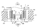
- FIG. 22 is a schematic cross-sectional view of a vertical shaft pump according to another embodiment.
- the rotary shaft 10 ′ passes through the impeller 22, and a bottom bearing 37 supported by the support member 13 is provided at the tip portion thereof.
- a bearing cover 38 for adjusting the water flow is provided on the opposite side of the bottom bearing 37 from the rotary shaft 10 ′.
- FIG. 23 is a cross-sectional view of a bearing device used as the bottom bearing 37 of the vertical shaft pump 3 shown in FIG.
- a sleeve 11 is provided on the outer periphery of the rotating shaft 10 ′, and the end of the rotating shaft 10 ′ is formed in a concave shape.
- a sleeve 14 is provided on the inner periphery of the concave end portion via a cushioning material 20b.
- the first sliding bearing 1 facing the sleeve 11 via the first clearance 7 is provided with a cushioning material 20 a on the back side (outer peripheral side) and fixed to the bearing case 12.
- a second slide bearing 9 is disposed on the inner peripheral side of the sleeve 14 with a second clearance 8 therebetween, and the inner peripheral surface of the sleeve 14 and the outer peripheral surface of the second slide bearing 9 are slid. It is configured to touch.
- the second plain bearing 9 is fixed by a bearing case 16, and the bearing case 16 is fixed to the support member 13 by a bolt 21c.
- the bearing case 16 is provided with a water supply port 19, and the water passed through the water supply port 19 passes through the first clearance 7 and the second clearance 8, so that this bearing device is a fluid lubrication bearing device. Function.
- the same effect as the bearing device shown in FIG. 6 can be obtained.
- the sleeve 14 at the end of the rotating shaft 10 ′, the diameter of the inner peripheral surface (second sliding surface) of the sleeve 14 can be reduced.
- the peripheral speed of the inner peripheral surface of the sleeve 14 can be reduced, and heat generation due to friction of the second slide bearing 9 can be suppressed.
- the second slide bearing 9 since the second slide bearing 9 is arranged near the end of the rotary shaft 10 ', the second slide bearing 9 can be easily attached and replaced, and this bearing device can be used in an existing vertical shaft pump. Can be easily applied.
- the bearing cover 38 is provided with a water supply port in a direction perpendicular to the water flow direction. Is more preferably configured to be connected to the water supply port 19 of the bearing case 16.
- FIG. 24 is a cross-sectional view of another bearing device used as the bottom bearing 37 of the vertical shaft pump 3 shown in FIG.
- the end of the rotating shaft 10 ' is formed in a concave shape, and a sleeve 14 is provided on the inner periphery of the concave end through a cushioning material 20b.
- the sleeve 14 is pressed from below by a pressing plate 36 and is fixed to the rotating shaft 10 ′. Further, the sleeve 14 is disposed at substantially the same position in the axial direction with respect to the sleeve 11. Thereby, the installation volume of this bearing apparatus can be made small.
- the ratio of the outer diameter of the second sliding bearing 9 to the inner diameter of the first sliding bearing 1 is 0.2 or more and 2.0 or less. Preferably there is. If the ratio of the diameter of the outer peripheral surface (slip surface) of the second slide bearing 9 exceeds this range, the peripheral speed of the sleeve 14 increases and heat generation due to friction during dry operation increases, which is not preferable.
- the second slide bearing has an outer diameter that is not less than 0.2 times the minimum diameter and not more than 2.0 times the maximum diameter. 9 is preferably used.
- the material used for the first sliding bearing 1 and the second sliding bearing 9 is a long-term bearing in dry operation and drainage operation. In order to function, a low coefficient of friction during dry operation and high wear resistance in water containing slurry are required.
- the first slide bearing 1 and the second slide bearing 9 are PA (polyamide), PBI (polybenzimidazole), POM (polyacetal), PBT (polybutylene terephthalate), PET (polyethylene terephthalate), PPE (polyphenylene ether), PC (polycarbonate), UHMW-PE (ultra high molecular weight polyethylene), PTFE (polytetrafluoroethylene), PPS (polyphenylene sulfide), PI (polyimide), PEEK (polyether ether ketone), PAR Abrasion resistance comprising a resin material comprising at least one of (polyarylate), PSF (polysulfone), PEI (polyetherimide), PAI (polyamideimide), PES (polyethersulfone), and PF (phenolic resin) High quality It is preferably formed of a fee.
- PA polyamide
- PBI polybenzimidazole
- POM polyacetal
- PBT poly
- first slide bearing 1 and the second slide bearing 9 are reinforced / modified materials containing a material obtained by adding carbon fiber, glass fiber, carbon particle, glass particle, graphite or the like to the resin material. More preferably, it is formed by.
- the 1st slide bearing 1 and the 2nd slide bearing 9 may be formed with the material containing ceramics or metals, such as silicon nitride and silicon carbide, from a viewpoint which needs to be provided with high abrasion resistance.
- the specific wear amount of these materials is at least 1 ⁇ 10 ⁇ 6 mm 2 / N or less, depending on the material, 1 ⁇ 10 ⁇ 7 mm 2 / N or less. For this reason, in the conventional structure, it was necessary to select a material having both low friction and wear resistance. However, since the above material has low friction, only the wear resistance needs to be considered.
- the sleeve 11 and the sleeve 14 can be formed of a metal material such as cemented carbide and stainless steel, ceramics, or a material containing the above resin material, and a material with high wear resistance is preferable.
- the materials of the first slide bearing 1 and the second slide bearing 9 may be different from each other.
- the materials of the sleeve 11 and the sleeve 14 may be different from each other.
- the present invention can reduce the destabilizing force no matter what friction coefficient is used for the first slide bearing 1, the second slide bearing 9, the sleeve 11 and the sleeve 14.
- the present invention is not limited to the vertical pump according to the above-described embodiment, but is a vertical pump having a slide bearing, particularly an air operation, an air / water agitation operation, an air / water mixing operation, a steady operation, and an air lock operation in the preceding standby operation.
- a vertical shaft pump in which the load applied to the bearing changes in each operating state and the destabilizing force changes.
- the vertical shaft pump according to each of the above embodiments is configured to be installed in the drainage station. Since the drainage station that drains rainwater for sewerage such as a combined type discharges water containing slurry, the vertical shaft pumps according to the above embodiments are suitable for the drainage station. In particular, in a drainage station that is a deep-type rainwater drainage facility and uses a post-sedimentation system in which a sedimentation basin is provided on the discharge side of the pump, a pre-sedimentation system drainage station in which a sedimentation basin is installed before the pump flows in. Since the amount of slurry is large as compared with the above, the vertical shaft pump according to each of the above embodiments can be used more suitably.
Landscapes
- Engineering & Computer Science (AREA)
- General Engineering & Computer Science (AREA)
- Mechanical Engineering (AREA)
- Physics & Mathematics (AREA)
- Fluid Mechanics (AREA)
- Chemical & Material Sciences (AREA)
- Ceramic Engineering (AREA)
- Structures Of Non-Positive Displacement Pumps (AREA)
- Sliding-Contact Bearings (AREA)
- Mounting Of Bearings Or Others (AREA)
Abstract
Description
Claims (16)
- 外周面に第1の摺動部を有し且つ内周面に第2の摺動部を有し、水中及び大気中で回転可能な回転部材と、
前記第1の摺動部を内周面で支持する第1のすべり軸受と、
前記第2の摺動部を外周面で支持する第2のすべり軸受と、を有する、立軸ポンプ。 - 前記第1のすべり軸受は、ドライ条件及び排水条件において前記第1の摺動部を支持可能に構成され、
前記第2のすべり軸受は、ドライ条件及び排水条件において前記第2の摺動部を支持可能に構成される、請求項1に記載された立軸ポンプ。 - 前記第1の摺動部と前記第1のすべり軸受との直径隙間の寸法は、前記第1のすべり軸受の内径の1/1000以上1/100以下であり、
前記第2の摺動部と前記第2のすべり軸受との直径隙間の寸法は、前記第2のすべり軸受の外径の1/1000以上1/100以下である、請求項1又は2に記載された立軸ポンプ。 - 前記第1の摺動部と前記第1のすべり軸受との直径隙間の寸法に対する前記第2の摺動部と前記第2のすべり軸受との直径隙間の寸法の比率が0.5以上2.0以下である、請求項1ないし3のいずれか一項に記載された立軸ポンプ。
- 前記第1の摺動部と前記第1のすべり軸受との直径隙間の寸法に対する前記第2の摺動部と前記第2のすべり軸受との直径隙間の寸法の比率が0.7以上1.3以下である、請求項4に記載された立軸ポンプ。
- 前記第1のすべり軸受の内径に対する前記第2のすべり軸受の外径の比率が0.2以上2.0以下である、請求項1ないし5のいずれか一項に記載された立軸ポンプ。
- 前記回転部材の水中に位置する部分の支持は前記すべり軸受のみで行われる、請求項1ないし6のいずれか一項に記載された立軸ポンプ。
- 前記すべり軸受は、PA、PBI、POM、PBT、PET、PPE、PC、UHMW-PE、PTFE、PPS、PI、PEEK、PAR、PSF、PEI、PAI、PES、及びPFのうち少なくとも1つを含む樹脂材料、セラミックス又は金属を含む、請求項1ないし7のいずれか一項に記載された立軸ポンプ。
- 前記すべり軸受は、炭素繊維、ガラス繊維、炭素粒子、ガラス粒子、及びグラファイトのうち少なくとも1つが添加された樹脂材料を含む、請求項8に記載された立軸ポンプ。
- 前記第1の摺動部と前記第1のすべり軸受との隙間、及び前記第2の摺動部と前記第2のすべり軸受との隙間へ水を通過させる流路が形成されている、請求項1ないし9のいずれか一項に記載された立軸ポンプ。
- 排水機場に設置可能に構成される、請求項1ないし10のいずれか一項に記載された立軸ポンプ。
- 前記流路に水を通水する給水口にストレーナを備える、請求項10に記載された立軸ポンプ。
- 前記すべり軸受を保持する軸受ケースを備え、
前記軸受ケースはその内周面に前記第1のすべり軸受を保持し、その外周面に前記第2のすべり軸受を保持する、請求項1ないし12のいずれか一項に記載された立軸ポンプ。 - 前記回転部材は回転軸であり、
前記第2の摺動部は前記回転軸の端部に設けられる、請求項1ないし13のいずれか一項に記載された立軸ポンプ。 - 前記第1のすべり軸受及び/又は前記第2のすべり軸受は、周方向に分割して構成される、請求項1ないし14のいずれか一項に記載された立軸ポンプ。
- 複数の軸受装置を備える立軸ポンプであって、前記軸受装置の少なくとも一つが、請求項1ないし15のいずれか一項に記載された前記第1のすべり軸受及び前記第2のすべり軸受を有する、立軸ポンプ。
Priority Applications (2)
| Application Number | Priority Date | Filing Date | Title |
|---|---|---|---|
| CN201480041832.6A CN105408635B (zh) | 2013-07-25 | 2014-07-24 | 立轴泵 |
| JP2015528330A JP6408990B2 (ja) | 2013-07-25 | 2014-07-24 | 立軸ポンプ |
Applications Claiming Priority (4)
| Application Number | Priority Date | Filing Date | Title |
|---|---|---|---|
| JP2013154919 | 2013-07-25 | ||
| JP2013-154919 | 2013-07-25 | ||
| JP2014-013371 | 2014-01-28 | ||
| JP2014013371 | 2014-01-28 |
Publications (1)
| Publication Number | Publication Date |
|---|---|
| WO2015012350A1 true WO2015012350A1 (ja) | 2015-01-29 |
Family
ID=52393384
Family Applications (1)
| Application Number | Title | Priority Date | Filing Date |
|---|---|---|---|
| PCT/JP2014/069555 Ceased WO2015012350A1 (ja) | 2013-07-25 | 2014-07-24 | 立軸ポンプ |
Country Status (3)
| Country | Link |
|---|---|
| JP (2) | JP6408990B2 (ja) |
| CN (2) | CN105408635B (ja) |
| WO (1) | WO2015012350A1 (ja) |
Cited By (7)
| Publication number | Priority date | Publication date | Assignee | Title |
|---|---|---|---|---|
| WO2017212533A1 (ja) * | 2016-06-07 | 2017-12-14 | 株式会社荏原製作所 | 立軸ポンプ |
| WO2017212534A1 (ja) * | 2016-06-07 | 2017-12-14 | 株式会社荏原製作所 | 立軸ポンプ |
| CN107532643A (zh) * | 2015-04-24 | 2018-01-02 | 株式会社荏原制作所 | 滑动轴承装置及具有该滑动轴承装置的泵 |
| WO2018234002A1 (de) * | 2017-06-19 | 2018-12-27 | Vibracoustic Gmbh | Lagerbuchse |
| JP2019015207A (ja) * | 2017-07-05 | 2019-01-31 | 株式会社荏原製作所 | 立軸ポンプ |
| US11644064B2 (en) | 2017-02-24 | 2023-05-09 | Vibracoustic Se | Bearing bush |
| NO20240240A1 (en) * | 2024-03-13 | 2025-09-15 | Rc Offshore As | Bottom support bearing |
Families Citing this family (3)
| Publication number | Priority date | Publication date | Assignee | Title |
|---|---|---|---|---|
| CN107365473A (zh) * | 2017-09-05 | 2017-11-21 | 北京嘉倍通科技有限公司 | 一种耐腐蚀轴承材料及其制备方法和应用 |
| JP6994194B2 (ja) * | 2017-11-30 | 2022-01-14 | 株式会社荏原製作所 | すべり軸受装置及びこれを備えたポンプ |
| US12392375B2 (en) | 2020-01-30 | 2025-08-19 | Ngi A/S | Sealing member for bearing housing |
Citations (6)
| Publication number | Priority date | Publication date | Assignee | Title |
|---|---|---|---|---|
| JPS6023676A (ja) * | 1983-07-15 | 1985-02-06 | Fujitsu Ltd | 潤滑ガスのラビリンス構造 |
| JPH0694035A (ja) * | 1992-09-10 | 1994-04-05 | Hitachi Ltd | 立軸排水ポンプ用軸受装置 |
| JP2000002190A (ja) * | 1998-06-15 | 2000-01-07 | Kubota Corp | 立軸ポンプのすべり軸受装置 |
| JP2003194046A (ja) * | 2001-12-28 | 2003-07-09 | Ishikawajima Harima Heavy Ind Co Ltd | 軸受装置及び立軸ポンプ |
| JP2007016884A (ja) * | 2005-07-07 | 2007-01-25 | Ge Medical Systems Global Technology Co Llc | 軸受機構およびx線管 |
| JP2009204034A (ja) * | 2008-02-27 | 2009-09-10 | Ishigaki Co Ltd | 滑り軸受ユニット及びこの滑り軸受ユニットを用いた先行待機型ポンプ |
Family Cites Families (14)
| Publication number | Priority date | Publication date | Assignee | Title |
|---|---|---|---|---|
| GB1587285A (en) * | 1977-06-14 | 1981-04-01 | Rolls Royce | Bearing assembly |
| AU579834B2 (en) * | 1983-09-30 | 1988-12-15 | Ebara Corporation | Combination of slide members |
| JP3104363B2 (ja) * | 1992-01-29 | 2000-10-30 | 株式会社日立製作所 | 立軸型揚水ポンプ |
| EP0561391B1 (en) * | 1992-03-18 | 1998-06-24 | Hitachi, Ltd. | Bearing unit, drainage pump and hydraulic turbine each incorporating the bearing unit, and method of manufacturing the bearing unit |
| JPH07224836A (ja) * | 1994-02-15 | 1995-08-22 | Mitsubishi Heavy Ind Ltd | 軸 受 |
| JP3187659B2 (ja) * | 1994-08-04 | 2001-07-11 | 株式会社日立製作所 | ポンプの運転方法及びポンプの軸受装置 |
| JP3727686B2 (ja) * | 1995-06-02 | 2005-12-14 | 三菱重工業株式会社 | 立軸ポンプにおける水中軸受の異物侵入防止装置 |
| JPH10238493A (ja) * | 1997-02-26 | 1998-09-08 | Kubota Corp | 横軸ポンプの水中軸受 |
| DE19903339A1 (de) * | 1999-01-28 | 2000-08-24 | Griptec Tech Produkte Gmbh | Gleitlager mit axial teilbaren Lagerschalenhälften |
| JP4116261B2 (ja) * | 2001-03-09 | 2008-07-09 | 株式会社荏原製作所 | 水中軸受構造及びポンプ装置 |
| JP2002317814A (ja) * | 2001-04-20 | 2002-10-31 | Kubota Corp | セグメント型すべり軸受 |
| JP2007263185A (ja) * | 2006-03-28 | 2007-10-11 | Kubota Corp | すべり軸受装置およびポンプ装置 |
| CN201269208Y (zh) * | 2008-09-12 | 2009-07-08 | 熊文安 | 采用石墨滑动轴承的可调控轴窜动的潜水电泵 |
| CN101943179A (zh) * | 2010-09-25 | 2011-01-12 | 江苏大学 | 硬质合金三组合径向滑动轴承 |
-
2014
- 2014-07-24 CN CN201480041832.6A patent/CN105408635B/zh active Active
- 2014-07-24 CN CN201710922716.0A patent/CN107605793B/zh active Active
- 2014-07-24 WO PCT/JP2014/069555 patent/WO2015012350A1/ja not_active Ceased
- 2014-07-24 JP JP2015528330A patent/JP6408990B2/ja active Active
-
2018
- 2018-09-21 JP JP2018177356A patent/JP6603382B2/ja active Active
Patent Citations (6)
| Publication number | Priority date | Publication date | Assignee | Title |
|---|---|---|---|---|
| JPS6023676A (ja) * | 1983-07-15 | 1985-02-06 | Fujitsu Ltd | 潤滑ガスのラビリンス構造 |
| JPH0694035A (ja) * | 1992-09-10 | 1994-04-05 | Hitachi Ltd | 立軸排水ポンプ用軸受装置 |
| JP2000002190A (ja) * | 1998-06-15 | 2000-01-07 | Kubota Corp | 立軸ポンプのすべり軸受装置 |
| JP2003194046A (ja) * | 2001-12-28 | 2003-07-09 | Ishikawajima Harima Heavy Ind Co Ltd | 軸受装置及び立軸ポンプ |
| JP2007016884A (ja) * | 2005-07-07 | 2007-01-25 | Ge Medical Systems Global Technology Co Llc | 軸受機構およびx線管 |
| JP2009204034A (ja) * | 2008-02-27 | 2009-09-10 | Ishigaki Co Ltd | 滑り軸受ユニット及びこの滑り軸受ユニットを用いた先行待機型ポンプ |
Cited By (9)
| Publication number | Priority date | Publication date | Assignee | Title |
|---|---|---|---|---|
| CN107532643A (zh) * | 2015-04-24 | 2018-01-02 | 株式会社荏原制作所 | 滑动轴承装置及具有该滑动轴承装置的泵 |
| WO2017212533A1 (ja) * | 2016-06-07 | 2017-12-14 | 株式会社荏原製作所 | 立軸ポンプ |
| WO2017212534A1 (ja) * | 2016-06-07 | 2017-12-14 | 株式会社荏原製作所 | 立軸ポンプ |
| US11644064B2 (en) | 2017-02-24 | 2023-05-09 | Vibracoustic Se | Bearing bush |
| WO2018234002A1 (de) * | 2017-06-19 | 2018-12-27 | Vibracoustic Gmbh | Lagerbuchse |
| CN110462236A (zh) * | 2017-06-19 | 2019-11-15 | 威巴克公司 | 支承衬套 |
| CN110462236B (zh) * | 2017-06-19 | 2021-08-10 | 威巴克欧洲股份公司 | 支承衬套 |
| JP2019015207A (ja) * | 2017-07-05 | 2019-01-31 | 株式会社荏原製作所 | 立軸ポンプ |
| NO20240240A1 (en) * | 2024-03-13 | 2025-09-15 | Rc Offshore As | Bottom support bearing |
Also Published As
| Publication number | Publication date |
|---|---|
| CN105408635B (zh) | 2017-10-27 |
| CN107605793B (zh) | 2019-08-23 |
| JP6603382B2 (ja) | 2019-11-06 |
| JP6408990B2 (ja) | 2018-10-17 |
| CN105408635A (zh) | 2016-03-16 |
| JPWO2015012350A1 (ja) | 2017-03-02 |
| JP2019023470A (ja) | 2019-02-14 |
| CN107605793A (zh) | 2018-01-19 |
Similar Documents
| Publication | Publication Date | Title |
|---|---|---|
| JP6603382B2 (ja) | 立軸ポンプ | |
| JP6411902B2 (ja) | 立軸ポンプ | |
| JP6422443B2 (ja) | すべり軸受装置 | |
| US20180216625A1 (en) | Shaft seal device and vertical pump with this shaft seal device | |
| JP6491215B2 (ja) | 立軸ポンプ | |
| JP6781020B2 (ja) | 立軸ポンプ | |
| JP6745876B2 (ja) | 立軸ポンプ | |
| CN106662109B (zh) | 立轴泵 | |
| JP6382147B2 (ja) | すべり軸受装置及びこれを備えたポンプ | |
| JP6749393B2 (ja) | 立軸ポンプ | |
| JP7158256B2 (ja) | 立軸ポンプ | |
| JP2017166590A (ja) | 軸受組立体および回転機械 | |
| JP2019015194A (ja) | 立軸ポンプ | |
| JP7410262B2 (ja) | すべり軸受装置及びポンプ | |
| JP6488207B2 (ja) | すべり軸受装置 | |
| JP4704066B2 (ja) | 立軸ポンプ | |
| JP6936062B2 (ja) | 立軸ポンプ | |
| JP2016130491A (ja) | 回転軸機構およびポンプ | |
| JP2022169190A (ja) | 水中軸受構造、立軸ポンプ、ポンプシステム及び潤滑液の供給方法 | |
| JP2019015193A (ja) | 立軸ポンプ |
Legal Events
| Date | Code | Title | Description |
|---|---|---|---|
| WWE | Wipo information: entry into national phase |
Ref document number: 201480041832.6 Country of ref document: CN |
|
| 121 | Ep: the epo has been informed by wipo that ep was designated in this application |
Ref document number: 14828984 Country of ref document: EP Kind code of ref document: A1 |
|
| ENP | Entry into the national phase |
Ref document number: 2015528330 Country of ref document: JP Kind code of ref document: A |
|
| NENP | Non-entry into the national phase |
Ref country code: DE |
|
| WWE | Wipo information: entry into national phase |
Ref document number: IDP00201601203 Country of ref document: ID |
|
| 122 | Ep: pct application non-entry in european phase |
Ref document number: 14828984 Country of ref document: EP Kind code of ref document: A1 |