EP0561391B1 - Bearing unit, drainage pump and hydraulic turbine each incorporating the bearing unit, and method of manufacturing the bearing unit - Google Patents
Bearing unit, drainage pump and hydraulic turbine each incorporating the bearing unit, and method of manufacturing the bearing unit Download PDFInfo
- Publication number
- EP0561391B1 EP0561391B1 EP93104379A EP93104379A EP0561391B1 EP 0561391 B1 EP0561391 B1 EP 0561391B1 EP 93104379 A EP93104379 A EP 93104379A EP 93104379 A EP93104379 A EP 93104379A EP 0561391 B1 EP0561391 B1 EP 0561391B1
- Authority
- EP
- European Patent Office
- Prior art keywords
- bearing
- sprayed coating
- bearing unit
- sleeve
- hardness
- Prior art date
- Legal status (The legal status is an assumption and is not a legal conclusion. Google has not performed a legal analysis and makes no representation as to the accuracy of the status listed.)
- Expired - Lifetime
Links
- 238000004519 manufacturing process Methods 0.000 title claims description 11
- 238000000576 coating method Methods 0.000 claims description 250
- 239000011248 coating agent Substances 0.000 claims description 234
- 238000010438 heat treatment Methods 0.000 claims description 110
- 229910003470 tongbaite Inorganic materials 0.000 claims description 60
- 239000000463 material Substances 0.000 claims description 55
- XLYOFNOQVPJJNP-UHFFFAOYSA-N water Substances O XLYOFNOQVPJJNP-UHFFFAOYSA-N 0.000 claims description 44
- 239000011230 binding agent Substances 0.000 claims description 33
- 229910010271 silicon carbide Inorganic materials 0.000 claims description 27
- 229910052751 metal Inorganic materials 0.000 claims description 20
- 239000002184 metal Substances 0.000 claims description 20
- HBMJWWWQQXIZIP-UHFFFAOYSA-N silicon carbide Chemical compound [Si+]#[C-] HBMJWWWQQXIZIP-UHFFFAOYSA-N 0.000 claims description 16
- 229910052581 Si3N4 Inorganic materials 0.000 claims description 15
- HQVNEWCFYHHQES-UHFFFAOYSA-N silicon nitride Chemical compound N12[Si]34N5[Si]62N3[Si]51N64 HQVNEWCFYHHQES-UHFFFAOYSA-N 0.000 claims description 15
- 229910052804 chromium Inorganic materials 0.000 claims description 9
- 229910052759 nickel Inorganic materials 0.000 claims description 9
- 229910045601 alloy Inorganic materials 0.000 claims description 7
- 239000000956 alloy Substances 0.000 claims description 7
- CWYNVVGOOAEACU-UHFFFAOYSA-N Fe2+ Chemical compound [Fe+2] CWYNVVGOOAEACU-UHFFFAOYSA-N 0.000 claims description 6
- 239000012530 fluid Substances 0.000 claims 3
- VNNRSPGTAMTISX-UHFFFAOYSA-N chromium nickel Chemical compound [Cr].[Ni] VNNRSPGTAMTISX-UHFFFAOYSA-N 0.000 description 86
- 229910001120 nichrome Inorganic materials 0.000 description 86
- UFGZSIPAQKLCGR-UHFFFAOYSA-N chromium carbide Chemical compound [Cr]#C[Cr]C#[Cr] UFGZSIPAQKLCGR-UHFFFAOYSA-N 0.000 description 57
- 229910017052 cobalt Inorganic materials 0.000 description 48
- 239000010941 cobalt Substances 0.000 description 48
- GUTLYIVDDKVIGB-UHFFFAOYSA-N cobalt atom Chemical compound [Co] GUTLYIVDDKVIGB-UHFFFAOYSA-N 0.000 description 48
- 238000000034 method Methods 0.000 description 32
- 239000010935 stainless steel Substances 0.000 description 32
- 229910001220 stainless steel Inorganic materials 0.000 description 32
- 239000002245 particle Substances 0.000 description 31
- VYPSYNLAJGMNEJ-UHFFFAOYSA-N Silicium dioxide Chemical compound O=[Si]=O VYPSYNLAJGMNEJ-UHFFFAOYSA-N 0.000 description 28
- 230000008859 change Effects 0.000 description 22
- 239000004576 sand Substances 0.000 description 19
- PXHVJJICTQNCMI-UHFFFAOYSA-N Nickel Chemical compound [Ni] PXHVJJICTQNCMI-UHFFFAOYSA-N 0.000 description 13
- 230000007797 corrosion Effects 0.000 description 12
- 238000005260 corrosion Methods 0.000 description 12
- 238000005507 spraying Methods 0.000 description 12
- 239000000919 ceramic Substances 0.000 description 11
- 230000000694 effects Effects 0.000 description 11
- 238000012360 testing method Methods 0.000 description 11
- 238000005516 engineering process Methods 0.000 description 10
- 238000010285 flame spraying Methods 0.000 description 10
- UONOETXJSWQNOL-UHFFFAOYSA-N tungsten carbide Chemical compound [W+]#[C-] UONOETXJSWQNOL-UHFFFAOYSA-N 0.000 description 10
- 230000006866 deterioration Effects 0.000 description 8
- 238000002474 experimental method Methods 0.000 description 7
- 239000013049 sediment Substances 0.000 description 7
- 239000006004 Quartz sand Substances 0.000 description 6
- 238000005299 abrasion Methods 0.000 description 6
- 239000011651 chromium Substances 0.000 description 6
- 230000003247 decreasing effect Effects 0.000 description 6
- VYZAMTAEIAYCRO-UHFFFAOYSA-N Chromium Chemical compound [Cr] VYZAMTAEIAYCRO-UHFFFAOYSA-N 0.000 description 5
- 238000005259 measurement Methods 0.000 description 5
- 230000008646 thermal stress Effects 0.000 description 5
- XEEYBQQBJWHFJM-UHFFFAOYSA-N Iron Chemical compound [Fe] XEEYBQQBJWHFJM-UHFFFAOYSA-N 0.000 description 4
- 239000000853 adhesive Substances 0.000 description 4
- 230000007423 decrease Effects 0.000 description 4
- 230000009545 invasion Effects 0.000 description 4
- 238000005461 lubrication Methods 0.000 description 4
- 238000005496 tempering Methods 0.000 description 4
- 229910000640 Fe alloy Inorganic materials 0.000 description 3
- 230000001070 adhesive effect Effects 0.000 description 3
- 230000000052 comparative effect Effects 0.000 description 3
- 239000003657 drainage water Substances 0.000 description 3
- 239000011888 foil Substances 0.000 description 3
- 230000006872 improvement Effects 0.000 description 3
- 238000003754 machining Methods 0.000 description 3
- 230000003647 oxidation Effects 0.000 description 3
- 238000007254 oxidation reaction Methods 0.000 description 3
- 230000002093 peripheral effect Effects 0.000 description 3
- 238000007750 plasma spraying Methods 0.000 description 3
- 238000001556 precipitation Methods 0.000 description 3
- 238000010791 quenching Methods 0.000 description 3
- 230000000171 quenching effect Effects 0.000 description 3
- 238000000926 separation method Methods 0.000 description 3
- 238000005245 sintering Methods 0.000 description 3
- 229910000831 Steel Inorganic materials 0.000 description 2
- 238000010283 detonation spraying Methods 0.000 description 2
- 239000007789 gas Substances 0.000 description 2
- 229910052742 iron Inorganic materials 0.000 description 2
- 230000007257 malfunction Effects 0.000 description 2
- 238000005498 polishing Methods 0.000 description 2
- 230000002265 prevention Effects 0.000 description 2
- 230000008569 process Effects 0.000 description 2
- 239000010453 quartz Substances 0.000 description 2
- 230000009467 reduction Effects 0.000 description 2
- 238000005096 rolling process Methods 0.000 description 2
- 239000010959 steel Substances 0.000 description 2
- 230000003746 surface roughness Effects 0.000 description 2
- ZOXJGFHDIHLPTG-UHFFFAOYSA-N Boron Chemical compound [B] ZOXJGFHDIHLPTG-UHFFFAOYSA-N 0.000 description 1
- OKTJSMMVPCPJKN-UHFFFAOYSA-N Carbon Chemical compound [C] OKTJSMMVPCPJKN-UHFFFAOYSA-N 0.000 description 1
- 229910000531 Co alloy Inorganic materials 0.000 description 1
- 238000006424 Flood reaction Methods 0.000 description 1
- 229910000990 Ni alloy Inorganic materials 0.000 description 1
- 229910018104 Ni-P Inorganic materials 0.000 description 1
- 229910018487 Ni—Cr Inorganic materials 0.000 description 1
- 229910018536 Ni—P Inorganic materials 0.000 description 1
- OAICVXFJPJFONN-UHFFFAOYSA-N Phosphorus Chemical compound [P] OAICVXFJPJFONN-UHFFFAOYSA-N 0.000 description 1
- 206010070834 Sensitisation Diseases 0.000 description 1
- 230000002411 adverse Effects 0.000 description 1
- 229910052782 aluminium Inorganic materials 0.000 description 1
- XAGFODPZIPBFFR-UHFFFAOYSA-N aluminium Chemical compound [Al] XAGFODPZIPBFFR-UHFFFAOYSA-N 0.000 description 1
- 238000000137 annealing Methods 0.000 description 1
- 229910052796 boron Inorganic materials 0.000 description 1
- 229910052799 carbon Inorganic materials 0.000 description 1
- 238000002485 combustion reaction Methods 0.000 description 1
- 238000005520 cutting process Methods 0.000 description 1
- 230000007547 defect Effects 0.000 description 1
- 238000005474 detonation Methods 0.000 description 1
- 239000006185 dispersion Substances 0.000 description 1
- 238000009713 electroplating Methods 0.000 description 1
- 238000005530 etching Methods 0.000 description 1
- 230000001747 exhibiting effect Effects 0.000 description 1
- 238000004880 explosion Methods 0.000 description 1
- 239000002360 explosive Substances 0.000 description 1
- 239000010433 feldspar Substances 0.000 description 1
- -1 ferrous metals Chemical class 0.000 description 1
- 239000007888 film coating Substances 0.000 description 1
- 238000009501 film coating Methods 0.000 description 1
- 230000006870 function Effects 0.000 description 1
- 239000011261 inert gas Substances 0.000 description 1
- 238000011835 investigation Methods 0.000 description 1
- 239000000314 lubricant Substances 0.000 description 1
- 230000007246 mechanism Effects 0.000 description 1
- 239000002923 metal particle Substances 0.000 description 1
- 238000005272 metallurgy Methods 0.000 description 1
- 239000000203 mixture Substances 0.000 description 1
- 229910052698 phosphorus Inorganic materials 0.000 description 1
- 239000011574 phosphorus Substances 0.000 description 1
- 238000007747 plating Methods 0.000 description 1
- 239000000843 powder Substances 0.000 description 1
- 238000003825 pressing Methods 0.000 description 1
- 239000012925 reference material Substances 0.000 description 1
- 239000013535 sea water Substances 0.000 description 1
- 230000008313 sensitization Effects 0.000 description 1
- 239000002002 slurry Substances 0.000 description 1
- 238000005728 strengthening Methods 0.000 description 1
- 230000035882 stress Effects 0.000 description 1
- 239000000126 substance Substances 0.000 description 1
Images


Classifications
-
- F—MECHANICAL ENGINEERING; LIGHTING; HEATING; WEAPONS; BLASTING
- F04—POSITIVE - DISPLACEMENT MACHINES FOR LIQUIDS; PUMPS FOR LIQUIDS OR ELASTIC FLUIDS
- F04D—NON-POSITIVE-DISPLACEMENT PUMPS
- F04D29/00—Details, component parts, or accessories
- F04D29/04—Shafts or bearings, or assemblies thereof
- F04D29/046—Bearings
- F04D29/047—Bearings hydrostatic; hydrodynamic
-
- C—CHEMISTRY; METALLURGY
- C23—COATING METALLIC MATERIAL; COATING MATERIAL WITH METALLIC MATERIAL; CHEMICAL SURFACE TREATMENT; DIFFUSION TREATMENT OF METALLIC MATERIAL; COATING BY VACUUM EVAPORATION, BY SPUTTERING, BY ION IMPLANTATION OR BY CHEMICAL VAPOUR DEPOSITION, IN GENERAL; INHIBITING CORROSION OF METALLIC MATERIAL OR INCRUSTATION IN GENERAL
- C23C—COATING METALLIC MATERIAL; COATING MATERIAL WITH METALLIC MATERIAL; SURFACE TREATMENT OF METALLIC MATERIAL BY DIFFUSION INTO THE SURFACE, BY CHEMICAL CONVERSION OR SUBSTITUTION; COATING BY VACUUM EVAPORATION, BY SPUTTERING, BY ION IMPLANTATION OR BY CHEMICAL VAPOUR DEPOSITION, IN GENERAL
- C23C4/00—Coating by spraying the coating material in the molten state, e.g. by flame, plasma or electric discharge
- C23C4/04—Coating by spraying the coating material in the molten state, e.g. by flame, plasma or electric discharge characterised by the coating material
- C23C4/06—Metallic material
-
- F—MECHANICAL ENGINEERING; LIGHTING; HEATING; WEAPONS; BLASTING
- F04—POSITIVE - DISPLACEMENT MACHINES FOR LIQUIDS; PUMPS FOR LIQUIDS OR ELASTIC FLUIDS
- F04D—NON-POSITIVE-DISPLACEMENT PUMPS
- F04D29/00—Details, component parts, or accessories
- F04D29/04—Shafts or bearings, or assemblies thereof
- F04D29/046—Bearings
- F04D29/0465—Ceramic bearing designs
-
- F—MECHANICAL ENGINEERING; LIGHTING; HEATING; WEAPONS; BLASTING
- F16—ENGINEERING ELEMENTS AND UNITS; GENERAL MEASURES FOR PRODUCING AND MAINTAINING EFFECTIVE FUNCTIONING OF MACHINES OR INSTALLATIONS; THERMAL INSULATION IN GENERAL
- F16C—SHAFTS; FLEXIBLE SHAFTS; ELEMENTS OR CRANKSHAFT MECHANISMS; ROTARY BODIES OTHER THAN GEARING ELEMENTS; BEARINGS
- F16C33/00—Parts of bearings; Special methods for making bearings or parts thereof
- F16C33/02—Parts of sliding-contact bearings
- F16C33/04—Brasses; Bushes; Linings
- F16C33/06—Sliding surface mainly made of metal
- F16C33/12—Structural composition; Use of special materials or surface treatments, e.g. for rust-proofing
- F16C33/122—Multilayer structures of sleeves, washers or liners
Definitions
- the present invention relates to a bearing unit comprising a bearing, and a sleeve which is in slide-contact with said bearing, as well as to a method of its manufacturing and to its preferred uses.
- the non-water-supply operation technology is to operate the drain pump while supplying no water to the space between a sleeve on a shaft and a bearing. Since no clear water supply apparatus is provided, a malfunction does not take place due to a failure of the clear water supply apparatus and that of the clear water supply sensor, resulting in satisfactory reliability. In order to enable the non-water-supply operation to be performed, a bearing unit must not be worn even if earth and sand contained in the drain invade thereto.
- a conventional bearing unit adapted to the non-water-supply technology has been constituted by a sleeve (a sintered article) made of tungsten carbide (hereinafter called "WC") exhibiting excellent wear resistance and corrosion resistance and by a ceramic bearing (a sintered article).
- WC tungsten carbide
- the structures constituted by combining the sleeve made of WC and the ceramic bearing has been disclosed in JP-A-60-81517 and JP-A-60-88215.
- the conventional bearing unit constituted by the WC sleeve and the ceramic bearing must employ a large-diameter sintered sleeve and a sintered bearing.
- the sintering technology cannot meet the requirements and the weight of the parts cannot be reduced, causing a difficulty to arise in assembling the bearing unit. Therefore, a hard film coating technology capable of coating a film having hardness equivalent to that of ceramics has been investigated energetically.
- a conventional bearing for a hydraulic turbine has been made of ceramics such as silicon carbide (SiC).
- a sprayed coating is used as the hard film for the bearing portion of a drain pump.
- the fact that the sprayed coating is inferior to a sintered article having the same composition in terms of the hardness and the strength causes an investigation for improving the hardness and the strength of the sprayed coating to be made.
- technology for improving the adhesive strength and the strength by plasma-spraying a material composed of, by weight, 50% chromium and 50% nickel and by holding the sprayed coating at from about 700°C to 800°C for from about 1 to 100 hours has been disclosed in JP-A-57-2872.
- JP-A-60-149762 is capable of strengthening the sprayed coating by forming a 20 to 80 wt% Ni-Cr sprayed coating, the main component of which is Ni-P on a ferrous material, and by subjecting them to a heat treatment set to from about 600°C to 1000°C.
- the precedent standby operation is an idle operation executed before commencement of drainage in a state where the water level is lower than the level at which the drainage operation can be performed.
- the precedent standby operation By performing the precedent standby operation, full power operation can be performed when the water level rises to a level at which the drainage can be performed. Therefore, rapid precipitation increase can be quickly coped with the subject system.
- the fact that the bearing must be idly performed without drain to be introduced into the sliding or bearing portion thereof for a short time causes the friction coefficient between the bearing and the sleeve must be extremely low so as to be freed from being damaged during the foregoing dry operation.
- a method capable of supplying external water to the sliding portion of the bearing at the time of the idle operation has been examined, resulting in a disclosure filed in JP-A-55-90718.
- the bearing In order to drain water containing earth and sand, the bearing must have satisfactory wear resistance. In particular, the non-water supply bearing must have wear resistance against slurry because clear water for protecting the bearing and the sleeves is not supplied.
- the major portion of the earth and sand is composed of feldspar and quartz. Therefore, earth and sand have a maximum hardness of about Vickers (Hv)1000 (which is the hardness of quartz). Accordingly, the hardness required for the bearing and the sleeve is Hv 1000 or higher.
- a sintered article composed of anyone of WC, SiC and silicon nitride (Si 3 N 4 ) is excellent in the hardness while revealing satisfactory wear resistance because these materials have a hardness of Hv 1000 or higher, that is, WC has a hardness of about Hv 1400, SiC has a hardness of about Hv 2800 and Si3N4 has a hardness of about Hv 1600.
- the sintering technology, the assembling facility and the manufacturing cost cause a limit to present in the size of the sleeve and the bearing that are fully made of a sintered material composed of WC, SiC or Si 3 N 4 . Therefore, there has been investigated the use of a hard film in place of the aforesaid sintered article.
- the film thickness must be several hundreds micron if the quantity of wear is taken into consideration, there is a limit in the method of manufacturing the hard film.
- a thermally-sprayed coating mainly composed of WC or Cr 3 C 2 and having a thickness of from about 100 to 200 ⁇ m has been widely used because a relatively thick film and satisfactory hardness can be obtained.
- the sprayed coating mainly composed of WC or Cr 3 C 2 generally has unsatisfactory hardness as compared with a sintered article although depending upon the material, the forming method and conditions, the aforesaid sprayed coating having a hardness of from about 600 Hv to 1000 Hv.
- Fig. 21 is a graph showing the wear rates measured by element experiments to be described later in the description about preferred embodiments.
- Each of sprayed coatings was formed on a stainless steel plate to serve as a rotary side specimen, while ⁇ - SiC was employed to serve as the stationary side specimen.
- the residual conditions were as follows: the surface pressure was 2 kg/cm 2 , the peripheral speed was 0.5 m/sec, the concentration of silica particles in earth and sand in water was 9 wt%. It is noted that the detailed shape of the specimen and the sliding method and the like were the same as those of the experimental conditions shown in Fig. 19 with regard to the preferred embodiments.
- the axis of abscissa of a graph shown in Fig. 21 stands for cross-sectional Vickers hardness of the sprayed coatings, and the axis of ordinate stands for relative wear ratio standardized while making the wear ratio of WC - 12% cobalt sintered article to be a reference.
- Sprayed coatings 1, 2 and 3 were conventional sprayed coatings formed by a high speed spraying method and a detonation spraying method and mainly composed of WC or Cr 3 C 2 .
- the wear resistance against water containing earth and sand considerably depends upon the hardness of the sprayed coating. It is preferred that a satisfactory effect can be obtained if the hardness is Hv 1000 or higher as described above.
- the conventional sprayed coating cannot enable satisfactory hardness and wear resistance against water containing earth and sand to be obtained.
- spraying is an operation in which not only hard particles such as WC or Cr 3 C 2 are heated and sprayed but also metal particles such as nickel, chromium or cobalt particles are mixed and simultaneously heated and sprayed.
- WC particles or Cr 3 C 2 particles are bound by molten metal of nickel, chromium or cobalt to form a film.
- the reason why the sprayed coating is lower in hardness than that of the sintered article is not that the WC or Cr 3 C 2 particles are not of a lower hardness but that the binder metal for binding the WC or Cr 3 C 2 particles has defects such as blow holes or that the binding strength between the binder metal and the WC or Cr 3 C 2 particles is not fully high.
- the spraying method has been improved variously.
- a high speed flame spraying method increasing the spraying velocity of the particles by utilizing the combustion energy of a combustible gas and a detonation spraying method utilizing a detonation of a combustible gas.
- the particle velocity at the time of spraying can be raised as compared with the speed realized when the conventional plasma sprayed coating is formed, resulting in a sprayed coating of higher hardness.
- the wear resistance against sediment water containing earth and sand is not fully high even if the sprayed coating is formed by anyone of the aforesaid spraying methods. It has been understood from the element test shown in Fig. 18 that the reason for this is that the hardness of the sprayed coating is lower.
- JP-A-60-81517 and JP-A-60-88215 are not technologies that have been established while taking into consideration the difficulty in the sintering technology, deterioration in the reliability and unsatisfactory assembling facility due to an increase in the weight caused from enlarging the diameter of the bearing and the sleeve.
- the improving methods for properties of the sprayed coating respectively according to the prior art, and disclosed in JP-A-57-2872 and JP-A-60-149762 encounter a limitation in coating materials for use therein.
- the coating material those having a thermal expansion coefficient which approximates that of ferrous alloys, which are primary base materials, or these which are not decomposed by the improving heat treatment, are used.
- an apparatus such as a pump that is used in water must be mainly made of stainless steel.
- the heat treatment temperature is higher than the annealing temperature of a stainless steel as a base material or the temperature at which the stainless steel is sensitized to intergranular corrosion.
- the hardness and the wear resistance of the base material deteriorate, causing a problem to arise in that the reliability deteriorates.
- the prior art has not been subjected to a consideration taken about the improvement in properties of the sprayed coating, the main component of which is WC that has a large difference in the thermal expansion coefficient from ferrous alloys. What is worse, no consideration has been made about change in the hardness of the base material and that in the wear resistance.
- JP-A-55-90718 and having the arrangement that external water is supplied to the sliding portion of the bearing arises a problem of reliability because the operation of the drainage facility is stopped due to a malfunction of an external water supply apparatus and the drainage operation can be stopped in an emergency.
- the US-A-4 912 835 discloses a tungsten carbide sprayed coating on a roll for use in rolling processes of non-ferrous metals.
- the tungsten carbide sprayed coating according to the US-A-4 912 835 contains nickel, chromium, or cobalt as binder material thereof.
- Another special feature of said sprayed coating is that the portion of the surface area of the coating covered by blow holes is less than 1.8 %.
- the US-A-4 997 324 discloses the use of a thermally sprayed tungsten carbide base cemented carbide powder on a spindle structure for a machine tool.
- the sprayed coating according to the US-A-4 997 324 contains cobalt and iron as binder materials thereof.
- the DE-A-37 33 117 discloses a pressurized air bearing unit the two parts of which comprise sprayed tungsten carbide coatings which contact each other only under low speed conditions.
- US-A-4 317 850 discloses a method for applying a tungsten carbide coating on a metal object, in particular a bearing bushing.
- tungsten carbide together with a bonding material which can be nickel, cobalt, iron, or chromium is sprayed onto a metal surface.
- a gas-tight metal foil is applied over the sprayed coating and the metal foil together with the sprayed coating is isostatically compressed onto the metal object under a pressure in the range from about 500 to 2000 bar at a temperature within a range from about 500°C to about 2000°C for a period from about 1/2 hour up to about 8 hours.
- the metal foil is removed.
- Another method for producing a heat and wear resistant coating on a steel object is disclosed in the JP-A-55 058 360.
- a nickel alloy or a cobalt alloy containing phosphorus and/or boron is deposited on the surface of the steel article by using an electroplating method or a chemical plating process.
- tungsten carbide mixed with cobalt, aluminum, or nickel as binder material thereof is sprayed onto the alloy layer. The entire structure is then heated up to 300 to 600°C.
- the object of the present invention is to provide a bearing unit with excellent wear resistance, assembling facility, and satisfactory reliability, to provide a method for manufacturing such a bearing unit, and preferable uses of such a bearing unit.
- this object is achieved by providing a bearing unit comprising a bearing, and a sleeve which is in slide-contact with said bearing, wherein from said bearing and said sleeve one is selected to be made of a ferrous alloy having a contact surface applied with a sprayed coating comprising WC or Cr 3 C 2 as the main component and at least one element of Ni, Cr and Co as binder material, wherein the number ratio of blow holes contained in the surface of said sprayed coating and having a size of not smaller than 20 ⁇ m is 15 per square millimeter or less.
- Preferred embodiments of this bearing unit are subjects of claims 2 to 8.
- the object is achieved by providing a method for manufacturing the bearing unit according to claim 9, and by using such a bearing unit in a drainage pump according to claims 10 to 12 or in a hydraulic turbine according to claims 13 and 14.
- the bearing unit exhibits excellent wear resistance and assembling facility and satisfactory reliability, and is adaptable to a hydraulic turbine or to a drainage pump system, preferably to a pump of a type operated while being freed from clear water supply to the bearing portion thereof.
- the wear resistance of a sprayed coating applied to the bearing surface of a bearing unit is improved by heating the sprayed coating, the main component of which is WC or Cr 3 C 2 , while determining the temperature conditions so as to make the sprayed coating to be freed from deterioration of the adhesive property and denaturing, and making the base material of stainless steel to be freed from excessive deterioration of the hardness and sensitization to intergranular corrosion due to thermal stress.
- the formed sprayed coating is preferably heated at a temperature from 300°C to 550°C for not shorter than one hour to have a hardness of not lower than Hv 1000 to have sufficient wear resistance against sediment water containing earth and sand.
- the material of the bearing and/or the sleeve applied with the sprayed coating is preferably stainless steel.
- the residual is of SiC or Si 3 N 4 provided at the contact or bearing surface thereof or may be entirely made of SiC or Si 3 N 4 .
- the sleeve or the bearing may be divided into two or more sections.
- the drainage pump or the hydraulic turbine according to the present invention incorporates a bearing unit characterized by anyone of the arrangements stated above.
- the sprayed coating may be formed on the contact surface of the bearing and/or the sleeve machined to have a predetermined shape and made of stainless steel and it may be subjected to finish machining so as to have a predetermined size.
- heating of a sprayed coating the primary component of which is WC or Cr 3 C 2
- the spraying coating mainly composed of WC or Cr 3 C 2 having a small thermal expansion coefficient is formed on a base made of a ferrous alloy (a stainless steel of JIS SUS403, for example, is used in the present invention)
- heating of the sprayed coating after the coating has been formed causes the following problems due to the difference in the thermal expansion coefficient between them: adhesion strength of the coating deteriorates due to the thermal stress, and WC particles or Cr 3 C 2 particles are oxidized, causing the properties of the sprayed coating to deteriorate.
- the hardness of the sprayed coating can be improved while eliminating adverse influence on the sprayed coating if proper heating conditions are selected.
- the hardness of the sprayed coating can be improved by heating it at from 300°C to 550°C for not shorter than one hour to have sufficient wear resistance against water containing earth and sand. The mechanism and the results of examinations will be described in the description of preferred embodiment later.
- blow holes are present in the sprayed coating, the strength of the sprayed coating is decreased. Furthermore, the binding strength between particles of WC or Cr 3 C 2 is also decreased, causing the particles of WC or Cr 3 C 2 to be separated from the coating during operation. As a result, the wear resistance deteriorates.
- heat treatment of the formed coating performed for the purpose of eliminating the blow holes will cause particles of the binder metal, and particles of WC or Cr 3 C 2 to be oxidized, adhesion strength of the sprayed coating to deteriorate, and the hardness and the corrosion resistance of the base material to deteriorate. As a result, the reliability deteriorates.
- the present invention enables the number of the blow holes in the sprayed coating to be decreased, the size of the blow hole to be reduced and the hardness of the sprayed coating to be improved by a heat treatment at a low temperature which does not cause the oxidation of the WC or Cr 3 C 2 sprayed coating, deterioration of adhesion strength of the coating due to the thermal stress and the deterioration of the hardness and the corrosion resistance of the base material.
- the above effects can be obtained by selecting the temperature and the time in which heating is performed.
- heat treatment conditions according to the present invention enables the number of large blow holes to be decreased, herein, the large blow holes being defined as those having a size of not smaller than 20 ⁇ m that is larger than the maximum particle size of particles of WC or Cr 3 C 2 .
- the large blow holes separate particles of WC or Cr 3 C 2 from the coating. Therefore, the decrease in the number of the large blow holes may improve the strength of the sprayed coating. If the number of the large blow holes are decreased, the sprayed coating is attained ductility, causing resistance against impact to be improved. As a result, occurrence of rupture and separation of the coating can be prevented and the reliability of the coating therefore is improved.
- the blow hole serves as the trigger point of corrosion of the sprayed coating
- the decrease in the number of the blow holes cause particles of WC or Cr 3 C 2 to be positioned more closely one another. Therefore, the corrosion generated among particles can be prevented and the corrosion resistance against drain can be improved.
- the drainage pump of the present invention is used to serve as a precedent standby operation drainage pump, the arrangement that the bearing, which can be operated without lubrication, is employed will enable satisfactory reliability to be attained.
- the manufacturing process can be simplified. It is especially suitable to a large-diameter pump.
- a drainage pump has two bearings respectively disposed adjacent to an impeller and in an upper portion thereof.
- a bearing unit according to this embodiment can be adapted to either of the two bearings.
- reference numeral 1 denotes a main shaft, 2 a sleeve fixedly attached on the main shaft 1, and 3 a bearing.
- the main shaft 1, the sleeves 2 and the bearings 3 were made of a stainless steel of JIS SUS403.
- the pump is provided with a plurality of pipes 30 each of which has a lower end opening in a drain suction port zone of a pump casing and an upper end opening in the atmosphere, and is vertically arranged along the outer surface of the casing, and which is supported by a rib of the casing at a lower end and by a floor of the drainage facility.
- the quantity of the flow is reduced and generation of vortexes in the drain level is restricted.
- the generation of the vortexes must be prevented because it causes vibration force to be generated, thus resulting in the vibration of the pump.
- the generation of the vortexes can be prevented even if the waver is a low level at which the vortexes are easily generated. Therefore, drainage can be performed stably.
- Fig. 2 is an enlarged view which illustrates the bearing unit disposed in the upper portion of the drainage pump shown in Fig. 1.
- Fig. 3 is an enlarged view which illustrates the bearing or contact portion shown in Fig. 2 while further enlarging the contact portion.
- the sleeves 2 and the bearing 3 are manufactured as follows: a sleeve base 8 and a bearing base 10 are manufactured by machining; and heat treatments of quenching and tempering are performed to improve the hardness of a stainless steel of JIS SUS403.
- the tempering temperature was so set to abut 700°C that the stainless steel of JIS SUS403 does not become brittle at the time of improving the property of the sprayed coating to be performed later.
- sprayed coatings 11 and 9 were formed on a sliding portion of the bearing 3 and the sleeve base 8 by a high speed flame spraying method, the sprayed coatings 11 and 9 being mainly composed of WC and containing NiCr as a binder metal.
- a heat treatment was performed by holding the bearing 3 and the sleeve base 8 at 400°C for 20 hours to improve the hardness of the sprayed coatings 9 and 11.
- the sleeve 2 and the bearing 3 were machined to respectively have predetermined inner and outer diameters and a predetermined surface roughness.
- the sleeve 2 is secured to the main shaft 1 by a rotation stopper 4.
- the bearing 3 was fastened to a metallic backing member 6 for the bearing 3 followed by being fixed by a fixing member 7 while interposing a buffer material 5 for the bearing 3. Furthermore, an invasion prevention member 12 for preventing invasion of sediment into the sliding portion was fastened to the bearing 3.
- this embodiment has the arrangement that stainless steel of JIS SUS403 is employed as the material for the sleeve base 8, its thermal expansion coefficient coincides with that of the material of the main shaft 1. As a result, generation of thermal stress can be prevented. Furthermore, the realized satisfactory toughness enables the sleeve to be obtained which is able to stably holding the sprayed coating formed on the surface thereof.
- the heat treatment applied to the WC sprayed coating enables the wear resistance to be improved, causing the durability and the reliability of the bearing unit to be improved.
- this embodiment has the arrangement that the sprayed coating to be formed on the sleeve and the bearing is mainly composed of WC and contains NiCr as the binder material, a similar effect was obtained from a sprayed coating, the main component of which was WC, and which used cobalt as the binder material, and a sprayed coating, the main component of which was Cr 3 C 2 , and which used NiCr as the binder material.
- the drainage pump exhibits stable bearing performance even if the bearing unit is under non-lubrication state, that is, non-water-supply state. If water is supplied, the drainage pump is able to further satisfactorily perform the bearing operation.
- the drainage pump has also an invasion prevention member to prevent invasion of sediment into the bearing or contact portion of the bearing unit. If sediment mixed with the drain, however, invades into the sliding portion, the operation can be performed stably because the bearing portion exhibits satisfactory wear resistance.
- the drainage pump can be reliably operated in a state where no-lubrication operation and lubricated operation are repeated, that is, in the precedent standby operation.
- Fig. 4 is a vertical cross sectional view which illustrates a bearing unit for a pump according to another embodiment of the present invention.
- the contact surface of the sleeve base 8 made of a stainless steel of JIS SUS403 is applied with the sprayed coating 9, the main component of which was WC, and which contained cobalt as the binder material.
- a bearing 13 which supports the sleeve 2 was made of SiC.
- the sleeve 2 was subjected to a heat treatment set to 400°C for 20 hours after the sprayed coating 9 has been formed to improve the hardness of the sprayed coating 9.
- the residual structures are the same as those according to the foregoing embodiment shown in Figs. 1 to 3.
- this embodiment has an arrangement that the material of the bearing portion is uniform, hard and sintered ceramics, the durability and the reliability of the bearing unit can be improved.
- this embodiment has the arrangement that the sprayed coating to be formed on the sleeve is mainly composed of WC and contains NiCr as the binder metal, a similar effect is obtained from a sprayed coating, the main component of which is WC, and which uses cobalt as the binder material, and a sprayed coating, the main component of which was Cr 3 C 2 , and which used NiCr as the binder material.
- Fig. 5 is a vertical cross sectional view which illustrates a bearing unit for a pump according to another embodiment of the present invention.
- This embodiment has an arrangement about a bearing structure capable of performing an idling operation even if the drainage water level does not reach the height of the bearing at the time of a precedent standby operation.
- the detailed cross sectional structure of the sleeve 2 is omitted from illustration in order to show the overall structure.
- a sprayed coating 11 the main component of which is WC, and which contained NiCr as the binder metal, is applied to the contact surface of the sleeve 2 made of stainless steel of JIS SUS403.
- the bearing 13 which supports the sleeve 2 is made of SiC.
- the bearing 13 is fastened to the metallic backing member 6 and fixed to a fixing member 7' while interposing the buffer material 5.
- a backing plate 17 is secured to the fixing member 7'.
- a rotary water tank 18 is secured to the main shaft 1. Water is enclosed in the rotary water tank 18 so that lubricant water is present in the contact portion of the bearing if the idle operation is performed in which the drainage water level does not reach the height of the bearing.
- the structure according to this embodiment encounters a fact that earth and sand are sometimes invaded into the contact portion at the time of the operation because the rotary water tank 18 easily accumulates the sediment.
- the sprayed coating 11 on the contact surface of the sleeve 2 has sufficient wear resistance attained due to the heat treatment, resulting no problem to arise.
- Figs. 6 and 7 respectively are views which illustrate a state where a sleeve of a bearing unit for a pump according to another embodiment of the present invention is fixed, and a cross sectional view which illustrates a fixing portion.
- the sleeve is divided into four sections in the circumference.
- Four sleeves 2a, 2b, 2c and 2d formed by the foregoing division were made of stainless steel of JIS SUS403.
- the sleeves 2a, 2b, 2c and 2d is subjected to a heat treatment set to 400°C for 20 hours.
- Each of the sleeve sections 2a, 2b, 2c and 2d is fixed to the main shaft 1 by two bolts 14 at the axial directional two portions thereof.
- the residual structures are the same as those according to the foregoing embodiments shown in Figs. 1 to 3.
- the sleeves sections 2a, 2b, 2c and 2d are manufactured by using stainless steel of JIS SUS403, and they are subjected to the heat treatment arranged similarly to that applied to the method of manufacturing the bearing.
- sprayed coating WC the main component of which is WC, and which contains NiCr or cobalt as the binder material, is formed on the contact surface of each sleeve by high speed flame spraying. After the sprayed coating has been formed, the sleeve is heated to 400°C and held at the temperature for 20 hours.
- the sleeve is fixed to the main shaft 1, and the sleeve is machined to have a predetermined size.
- the bolts are sufficient to fix the sleeve to the main shaft 1, use of an adhesive agent will improve the reliability.
- this embodiment has an arrangement that the sleeve is divided into a plurality of sections, the operation for forming the sprayed coating can be facilitated. Furthermore, the width of each of the divided sleeves can be reduced to a quarter of the corresponding integrated sleeve, causing an effect to be obtained in that the sleeve can be handled easily.
- Fig. 8 is a schematic view partially including a cross sectional view which illustrates a bearing of a bearing unit for a pump according to another embodiment of the present invention.
- This embodiment has an arrangement that bearing sections 19 formed by dividing the bearing portion of a bearing are arranged.
- Each of the bearing sections 19 is produced by forming the sprayed coating 11 thereon, the main component of which is WC, and which contains NiCr or cobalt as the binder metal, by high speed flame spraying on the base 10 made of stainless steel of JIS SUS403. After the sprayed coating has been formed, a heat treatment set at 400°C for 20 hours is performed to improve the hardness of the sprayed coating.
- the bearing sections 19 are fastened to the metallic backing member 6 while interposing the buffer material 5, the bearing sections 19 being then disposed in a bearing housing 20. Although the bearing sections 19 are fastened to the bearing housing 20 by a fixing jig 21, use of an adhesive agent will improve the reliability.
- this embodiment has an arrangement that the bearing portion of the bearing is divided into a plurality of sections, the sprayed coating can easily be formed. Furthermore, the arrangement that each sliding section 19 is fixed while interposing the buffer material 5 will effectively prevent an unsymmetrical contact.
- the sleeve which has been made by sintered carbide mainly composed of WC can be made of a stainless steel according to the present invention. Therefore, the weight can be considerably reduced. Furthermore, the arrangement that the sleeve base is made of stainless steel will enable thread hold machining to be performed. Therefore, handling can be facilitated. In particular, a significant effect can be obtained from the present invention if a sleeve has a large diameter.
- the effects of the present invention attained to reduce the weights of sleeves are collectively shown in Fig. 9.
- Fig. 9 is a graph which illustrates the relationship between the outer diameters (hereinafter abbreviated to symbol "D") and the weights (hereinafter abbreviated to symbol "W”) of sleeves. Since the sleeve weight "W" is varied when the outer diameter "D" of the sleeve is changed, the relationship is standardized to W/D 2 . According to the present invention, a W/D 2 of 0.05 or less is attained.
- Fig. 10 is a cross sectional view which illustrates a hydraulic turbine which incorporates the bearing unit according to the present invention as the bearing for the hydraulic turbine.
- reference numeral 22 represents a main shaft for a hydraulic turbine
- 23 represents a sleeve rotation stopper.
- Reference numeral 24 represents a sleeve made of stainless steel of JIS SUS403 manufactured by forming a sprayed coating (hereinafter called a "WC - 27% NiCr sprayed coating"), the main component of which is WC, and to which NiCr is added by 27 weight % as a binder metal, followed by heat treatment applied thereto.
- a sprayed coating hereinafter called a "WC - 27% NiCr sprayed coating”
- Reference numeral 25 represents a bearing made of stainless steel of JIS SUS403 manufactured by forming a sprayed coating (hereinafter called a Cr 3 C 2 - 25 % NiCr sprayed coating), the main component of which is Cr 3 C 2 subjected to a heat treatment, and to which NiCr is added as a binder metal by 25% and by applying heat treatment.
- the sprayed coating was formed on the surface of the sleeve and the bearing by using a high speed flame spraying method.
- the sprayed coating subjected to the heat treatment has wear resistance similar to that attained from the sintered article.
- the aperture can easily be enlarged and therefore an effect of reducing the cost and the weight can be obtained if the arrangement of this embodiment is adapted to a hydraulic turbine.
- the wear resistance properties of the bearing according to the foregoing embodiment were evaluated by examining the change in the hardness of the sprayed coating taken place due to heat treatment applied.
- the change in the hardness of the sprayed coating was examined under conditions: heating temperature was ranged from 200°C to 600°C; and heating time was ranged from 1 to 30 hours.
- the hardness of the sprayed coating was measured by a Vickers hardness meter. In order to eliminate the influence of the base, the hardness was measured at the cross sectional of the sprayed coating and a load of 300 g is equally applied.
- Fig. 11 illustrates a portion of the results of the aforesaid measurements, wherein change in the hardness taken place when a WC - 27 % NiCr sprayed film is heated to 400°C is shown.
- the axis of abscissa stands for the heating time, while the axis of ordinate stands for the hardness of the sprayed coating.
- the sprayed coating was formed by high speed flame spraying to have a thickness of about 100 ⁇ m after the surface has been polished.
- the base is made of stainless steel of JIS SUS403 subjected to heat treatments of quenching and tempering at about 700°C. Since the values of the measured hardness disperse, ten points were measured to show the maximum value and the minimum value of the measured values are designated by a line while showing average values by a mark " ⁇ "
- the hardness of the sprayed coating increases with heat treatment time and reaches its maximum hardness in 10 to 30 hours. Then, the hardness becomes substantially constant value although slight dispersion takes place.
- the maximum value of the average hardness is Hv 1014 (maximum value Hv 1065 and minimum value Hv 890).
- the thus attained hardness is inferior to an average value of Hv 1317 (maximum value Hv 1404 and minimum value Hv 1235) of the hardness of a sintered article (hereinafter called a "WC - 12% cobalt sintered article), the main component of which is WC, and to which cobalt is, as the binder, added by 12 weight %.
- an increase of an average value of about 34% is attained as compared with an average value of Hv 727 (maximum value Hv 869 and minimum value Hv 604) of the hardness realized before the heat treatment is performed, resulting in a significant improvement.
- Fig. 12 illustrates a part of the results of the measurements, wherein change in the hardness taken place when a WC - 27% NiCr sprayed coating is heated to 500°C is shown similarly to Fig. 11.
- the method of forming the sample, the shape of the same and the method of measuring the hardness are the same as those employed to obtain the results shown in Fig. 11.
- the hardness of the sprayed coating substantially reaches the maximum hardness when the sample is heated for about 1.5 hours.
- the maximum value of the average hardness is Hv 1115 (maximum value Hv 1139 and minimum value Hv 1084).
- the averaged value is increased by about 47% as compared with the hardness realized before the heat treatment is applied, resulting in similar hardness to that of the WC-12% cobalt sintered article.
- Fig. 13 shows a part of the results of the measurements, wherein change in the hardness taken place when a sprayed coating (hereinafter called a WC - 12% cobalt sprayed coating), the main component of which is WC, and to which cobalt is, as the binder material, added by 12 weight %, is heated to 400°C is shown. Also the WC - 12% cobalt sprayed coating is formed by the high flame spraying similarly to each sample shown in Figs. 11 and 12 to have a thickness of about 100 ⁇ m after its surface has been polished.
- the base is made of stainless steel of JIS SUS403 subjected to the heat treatment.
- the hardness of the WC - 12% cobalt sprayed coating increases with heat treatment time and reaches the maximum hardness in 10 to 20 hours, followed by slight deterioration in 25 hours.
- the average value of the maximum hardness is Hv 946 (maximum value Hv 1149 and minimum value Hv 792).
- An increase in the average value of about 62% is attained as compared with an average hardness value of Hv 584 (maximum value Hv 1149 and minimum value Hv 490) realized before the heat treatment.
- a similar hardness change to that attained in the case of the WC - 27% NiCr sprayed coating was taken place in the case where heating to 500°C was performed. In this case, the maximum hardness was attained by performing heating for about one hour.
- Fig. 14 shows a portion of the results of the measurements, wherein change in the hardness is shown which takes place when a Cr 3 C 2 - 25% NiCr sprayed coating is heated at 400°C. Also the Cr 3 C 2 - 25% NiCr sprayed coating is formed by a similar high speed flame spraying employed to form each sample for use in the measurement shown in Figs. 11, 12 or 13 to have a thickness of about 100 ⁇ m after its surface has been polished.
- the base is made of stainless steel of JIS SUS403 subjected to the heat treatment.
- the shape of the sample and the method of measuring the hardness are the same as those employed to obtain the results shown in Figs. 11, 12 and 13.
- the hardness of the Cr 3 C 2 - 25% NiCr sprayed coating gradually increases with heat treatment time.
- the maximum value of the average hardness in 25 hours of heating is Hv 958 (maximum value Hv 1043 and minimum value Hv 905).
- the average value increased by about 21% as compared with an average value Hv 791 (maximum value Hv 817 and minimum value Hv 744) of the hardness before the heat treatment is performed.
- the attained increase is inferior to that realized in the case of the WC - 27% NiCr sprayed coating and the WC - 12% cobalt spray coating.
- the hardness increases with time like the case in which heating to 400°C is performed, resulting in a larger degree.
- the hardness of each of the foregoing WC-27% NiCr sprayed coating, the WC-12% cobalt sprayed coating and the Cr 3 C 2 - 25% NiCr sprayed coating is significantly improved due to the heating from 400°C to 500°C, resulting in hardness equivalent to the hardness of WC - 12% cobalt sintered article. It can be considered that the heating from 400°C to 500°C increases the binding strength for particles of WC or Cr 3 C 2 with the binder material in the sprayed coating to a level substantially equivalent to the sintered article.
- the results of examinations of the heating temperature range from 200°C to 600°C and a heating time range from 1 to 30 hours will now be described.
- the heat treatment temperature be 300°C or higher, more preferably 350°C or higher.
- ferrous alloys for use to form the pump has a thermal expansion coefficient of about 12 to 17 x 10 -6 /°C and WC or Cr 3 C 2 type sprayed coating has a thermal expansion coefficient of about 5 to 7 x 10 -6 /°C.
- the heat treatment performed in the atmosphere will cause an oxidation of the sprayed coating to take place, resulting in a deterioration of the wear resistance.
- the heat treatment temperature must be set to 550°C or lower, preferably 500°C or lower. In order to prevent the oxidation of the sprayed coating, it is preferred to perform heating in inert gas or in vacuum.
- Fig. 15 shows a microscopic photograph of a state where the WC - 27 % NiCr sprayed film formed to have a thickness of abut 200 ⁇ m was heated at 400°C followed by performing surface polishing until the thickness is reduced to about 100 ⁇ m, and heating is again performed followed by performing polishing to attain a mirror surface. The final thickness is about 90 ⁇ m.
- Fig. 15A is a photograph of the surface of non-treated sprayed coating
- Fig. 15B is a photograph of the surface of the sprayed coating after it has been heated for 10 hours
- Fig. 15C is a photograph of the surface of the sprayed coating after it has been heated for 20 hours. Each of the photographs are taken at a magnification of 100 times.
- Figs. 15A, 15B and 15C dotty black portions are blow holes. Comparing Figs. 15A, 15B and 15C, the number of the blow holes decreases and the size of the same is reduced with a lapse of the heat treatment time.
- the samples for use in the experiments are, by cutting, obtained from a sprayed coating formed on a plate (26 mm x 26 mm) made of stainless steel of JIS SUS403, the difference in the number of the blow holes has not taken place due to the spraying conditions but has taken place due to the fact that the number of the blow holes has decreased by the heat treatment. A similar phenomenon was observed in the WC - 12% cobalt sprayed coating or the Cr 3 C 2 - 25% NiCr sprayed coating.
- Fig. 16 illustrates the relationship between the heating time and density of blow holes having a size larger than 20 ⁇ m observed on the surface when the WC - 27% NiCr sprayed coating is heated at 400°C. It should be noted that the method of observing the blow holes formed in the surface is the same as the method employed to obtain the results shown in Fig. 15. When the structure of the WC-27% NiCr sprayed coating was observed by a scanning type electronic microscope, the average particle size of the WC particles and the particle of the NiCr binder material was about 10 ⁇ m and the maximum size was 20 ⁇ m or less. Therefore, the presence of blow holes having a size of several ⁇ m does not affect the separation of the WC particles.
- blow holes are meant blow holes having a size of 20 ⁇ m hereinafter.
- the number of blow holes rapidly increases if the sprayed coating is heated at 400°C for 15 hours or longer.
- the change in the number ratio of the blow holes coincides with the change in the hardness shown in Fig. 7. That is, it can be considered that the change in the hardness of the sprayed coating due to heating takes place depending upon the number ratio of the blow holes in the sprayed coating.
- the relationship between the number ratio of the blow holes and the hardness obtained from the change in the hardness of the heating time and the change in the number ratio of the blow holes respectively shown in Figs. 12 and 16 is shown in Fig. 17. If the number ratio of the blow holes is 30 per square milimeter (mm 2 ) or lower, the hardness commences to increase, and the hardness preferable for the bearing portion of the pump is realized when the number ratio is 15 per square milimeter (mm 2 ) or lower.
- the sprayed coating to be applied to the bearing portion of the pump has a number ratio of the blow holes having a size larger than 20 ⁇ m and present in the surface of 15 per square milimeter (mm 2 ) or less, preferably 10 per square milimeter (mm 2 ) or less. It is noted that the WC -12 % cobalt sprayed coating and the Cr 3 C 2 - 25% NiCr sprayed coating as well as attained a similar phenomenon.
- a rotation-side specimen 15 shown in Fig. 15A and a stationary-side specimen shown in Fig. 15B are dipped in water containing quartz sand and assumed to be water containing earth and sand. Then, the rotary-side specimen is rotated as shown in Fig. 18D to be slid while being applied with a predetermined surface pressure.
- the abrasion losses of the two specimens were measured.
- the wear losses were evaluated by measuring the thickness of the rotation-side specimen 15 before and the after the test.
- the surface shape of the stationary-side specimen 16 before and after the test was measured by a surface roughness meter.
- the examining conditions are as follows: the surface pressure is 1 to 10 kg/cm 2 , the peripheral speed is about 0.5 to 5 m/sec, and concentration of quartz sand is 0.1 to 10 wt%.
- the sliding test was repeated as follows: the water containing earth and sand was changed at each sliding operation covering a distance of 3.6 km in order to reduce the influence of the wear of the quartz sand; and the quartz sand was interposed between the two specimens whenever water containing earth and sand was changed in order to cause the quartz sand to be easily caught between the two specimens.
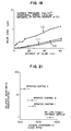
- Fig. 19 shows a portion of results of the experiments of the wear resistance of the sprayed coating subjected to the heat treatment.
- the axis of abscissa stands for the distance of sliding and the axis of ordinate stands for the average wear loss of the rotational side specimen.
- the stationary-side specimen is ⁇ - SiC, while the rotation-side specimen is WC - 27% NiCr sprayed coating having a thickness of about 100 ⁇ m.
- the base is made of stainless steel of JIS SUS403 subjected to heat treatments of quenching and tempering. The conditions of the heat treatment applied to the sprayed coating was determined while referring to the results shown in Fig. 12 to be 400°C for 20 hours.
- a WC - 12% cobalt sintered article and non-treated WC - 27% NiCr sprayed coating were used as the rotation-side specimens under the similar conditions.
- the residual test conditions are as follows: the surface pressure is 2 kg/cm 2 , the peripheral speed is 0.5 m/s and the concentration of the quartz sand is 9 wt%.
- a line (1) expressed by - ⁇ - shows the change in the abrasion loss of the WC - 27 % NiCr sprayed coating subjected to the heat treatment and applied to the bearing member according to the present invention
- a line (2) expressed by -o- shows the change in the wear loss of WC - 12% cobalt sintered article which is the comparative material applied to the conventional bearing member
- a line (3) expressed by - ⁇ - shows the change in the wear loss of the WC - 27% NiCr sprayed coating which is the comparative material and to which no heat treatment is applied.
- the wear rate of the WC - 27% NiCr sprayed coating which is not subjected to the heat treatment is about three times the wear loss of the WC - 12% cobalt sintered article.
- the wear rate of the WC - 27% NiCr sprayed coating is substantially the same as the wear rate of the WC - 12% cobalt sintered article. That is, the heat treatment set to 400°C for 20 hours causes the wear loss of the WC - 27% NiCr sprayed coating against water containing earth and sand was reduced to one-third. It can be considered that the foregoing reduction in the abrasion loss was caused from the increase in the hardness due to the heat treatment shown in Fig. 12 to which the sprayed coating was subjected.
- the wear resistance of the sprayed coating subjected to the heat treatment is a reasonable value because of the relationship between the hardness of the sprayed coating and the abrasion rate shown in Fig. 21.
- the WC - 12% cobalt sprayed coating enables a similar effect to be obtained from a similar heat treatment as a result of a similar experiment.
- the WC - 12% cobalt sprayed coating does not enable the hardness to be improved unlikely the WC - 27% NiCr sprayed coating. Therefore, the wear resistance of the WC - 12% cobalt sprayed coating is inferior to that of the WC - 12% cobalt sintered article and that of the WC - 27% NiCr sprayed coating subjected to the heat treatment.
- cobalt employed as the binder material is inferior to NiCr in terms of the corrosion resistance. Therefore, there is a possibility of generation of abrasion due to corrosion.
- Cr 3 C 2 - 25% NiCr sprayed coating enables improved wear resistance to be realized.
- the realized improvement in the wear resistance is inferior to that realized in the WC - 27% NiCr sprayed coating and and WC-12% cobalt sprayed coating.
- the reason for this is that the fact that inherent hardness of the Cr 3 C 2 - 25% NiCr sprayed coating is inferior to the hardness of the WC - 27% NiCr sprayed coating and that of WC-12 % cobalt sprayed coating deteriorates the effect of the heat treatment.
- Fig. 20 collectively shows the wear rates of the results shown in Fig. 19, results obtained when WC - 27% NiCr sprayed coatings are used in both the stationary-side and the rotation-side specimens, and those obtained when the WC - 27% NiCr sprayed coating was used as the rotation-side specimen and the Cr 3 C 2 - 25% NiCr sprayed coating subjected to the heat treatment was used as the stationary-side specimen.
- Fig. 20 shows the wear rates of the stationary-side and the rotation-side specimens after they were subjected to the experiment for 60 hours.
- the test conditions are the same as those of the experiment shown in Fig. 19.
- the relative wear rates shown on the axis of ordinate are values of the wear rates of specimens expressed by relative values while making the wear rate of the rotation-side and the stationary-side specimens of (A) which is the combination of WC - 12% cobalt sintered article and ⁇ - SiC to be a reference value 1.0.
- the bars each having diagonal lines entered therein stand for the wear rates of the rotation-side specimens and the bars having no diagonal lines stand for the wear rates of the fixed-side specimens.
- the combination (A) is a combination of the WC - 12% cobalt sintered article and ⁇ - SiC and is the results of a curve (2) shown in Fig. 19.
- Combination (B) is a result of a combination of WC - 27% NiCr sprayed coating subjected to no heat treatment designated by curve (3) shown in Fig. 19 and ⁇ - SiC.
- Combination (C) is a result of a combination of the WC - 27% NiCr sprayed coating subjected to the heat treatment which is the material of the bearing according to the present invention and designated by curve (1) shown in Fig 19 and ⁇ - SiC.
- Combination (D) is a result of a combination of the WC - 27% NiCr sprayed coating subjected to the heat treatment which is the material for the bearing according to the present invention and the WC - 27% NiCr sprayed coating subjected to the heat treatment.
- Combination (E) is a result of a combination of the WC - 27% NiCr sprayed coating subjected to the heat treatment and the Cr 3 C 2 - 25% NiCr sprayed coating subjected to the heat treatment. It should be noted that the conditions of the heat treatment to which the each sprayed coating is subjected are as follows: 400°C for 20 hours.
- the combination (C) enables both of the stationary-side specimen and the rotation-side specimen to have the wear resistance substantially equivalent to that attained from combination (A), that is, the combination of the WC - 12% cobalt sintered article and ⁇ - SiC.
- the combination (D) having the arrangement that the WC - 27% NiCr sprayed coatings subjected to the heat treatment are used in both of the stationary-side specimen and the rotation-side specimen enabled the rotation-side specimen and the stationary-side specimen to have the wear resistance substantially equivalent to that of the WC - 12% cobalt sintered article.
- the WC - 27% NiCr sprayed coating subjected to the heat treatment for use in the stationary-side specimen exhibited excellent wear resistance superior to that of ⁇ - SiC.
- the hardness of ⁇ - SiC is an average value of Hv 2704 (maximum value Hv 2874 and minimum value Hv 2591) which is considerably superior to the hardness of the WC - 27% NiCr sprayed coating subjected to the heat treatment.
- the fracture toughness of ⁇ - SiC is about 3.9 (MN/m. m) which is inferior to that of the WC - 27% NiCr sprayed coating, that is about 13 (MN/m. m). It can be considered that the excellent fracture toughness of the WC - 27% NiCr sprayed coating subjected to the heat treatment affects the wear resistance rather than the hardness does and the foregoing excellent wear resistance is obtained. It should be noted that the fracture toughness was measured by a Vickers impression method.
- the wear rate of the Cr 3 C 2 - 25% NiCr sprayed coating subjected to the heat treatment and used as the fixed-side specimen was higher than that of ⁇ - SiC and that of the WC - 27% NiCr sprayed coating subjected to the heat treatment.
- the reason for this lies in that the hardness of the Cr 3 C 2 - 25% NiCr sprayed coating cannot be significantly improved even if it is subjected to the heat treatment.
- the Cr 3 C 2 - 25% NiCr sprayed coating exhibited equivalent or superior wear resistance to that of the WC - 27% NiCr sprayed coating if the temperature of the drain is high. It can be considered that the reason for this lies in that the hardness of the Cr 3 C 2 - 25% NiCr sprayed coating does not deteriorate considerably at high temperature.
- the combination of the WC - 27% NiCr sprayed coating subjected to the heat treatment and the Cr 3 C 2 - 25% NiCr sprayed coating subjected to the heat treatment causes a satisfactory effect to be obtained depending upon the condition for use.
- the WC - 27% NiCr sprayed coating subjected to the heat treatment is used in the sleeve to be combined with a bearing made of SiC or Si 3 N 4 , excellent wear resistance and sliding characteristics can be obtained.
- SiC or Si3N4 be used in the bearing having a structure which is supported by the metallic backing member by shrinkage fit because the strength of SiC and Si3N4 is improved due to compressive stress applied thereto. If the WC - 27% NiCr sprayed coating subjected to the heat treatment is used in both of the sleeve and the bearing, totally excellent wear resistance and sliding characteristics can be attained.
- the WC sprayed coating containing cobalt as the binder material as well as exhibits excellent wear resistance it is difficult to be used because of a problem of corrosion if drain contains salinity. If the WC - 27% NiCr sprayed coating and the Cr 3 C 2 - 25% NiCr sprayed coating subjected to the heat treatment are used as the sleeve and the bearing, the obtained wear resistance is inferior to that obtainable from the combinations of the WC - 27% NiCr sprayed coatings. However, further improved characteristics can be realized if the temperature of the drain is high. In this case, the WC - 27% NiCr sprayed coating may be employed in either of the sleeve or the bearing, resulting in the similar characteristics.
- the bearing structure according to the present invention enables the contact surface of each of the sleeve and the bearing to have similar wear resistance to that realized by a structure in which WC - 12% cobalt sintered alloy is used as the bearing. Furthermore, assembling facility can be improved because the weight of the sleeve and bearing can be reduced. In addition, the fact that the sleeve and the bearing reveal excellent toughness will prevent fracture due to impact, causing the reliability to be improved. Therefore, a rotational machine such as a pump and a hydraulic turbine that incorporates the bearing structure according to the present invention is attained satisfactory reliability.
- each of the foregoing embodiments employs the high speed flame spraying method for forming the sprayed coating
- an explosive spraying method for forming the sprayed coating
- a pressure reduction plasma spraying method for forming the sprayed coating
- a laser spraying method for forming the sprayed coating
- a plasma spraying method may be employed while freed from particular limitation. It should be noted that it is preferable that the hardness before the heat treatment is performed is higher. It is preferable to employ the high speed flame spraying method or the explosion spraying method because a hard sprayed coating can be formed.
- each of the foregoing embodiments employs stainless steel of JIS SUS 403 as the material for the sleeve base and the bearing base, another material which can be used in water may be employed. Furthermore, it is preferred to employ stainless steel of JIS SUS403 in place of stainless steel of JIS SUS304 because of a larger thermal expansion coefficient if the thermal expansion coefficient of the sprayed coating, the main component of which is WC or Cr 3 C 2 . In addition, it is preferable to employ stainless steel of JIS SUS304L or JIS SUS316L containing low carbon if the deterioration of the corrosion resistance of the stainless steel due to the heat treatment is taken into consideration.
- each of the foregoing embodiments employs NiCr and cobalt as the binder material by contents of 12 wt%, 25 wt% and 27 wt%, the content is not limited if the characteristics required for the sprayed coating are met.
- the present invention has the arrangement that the sprayed coating, the main component of which is WC or Cr 3 C 2 , is heated under a predetermined condition. Therefore, the binding strength between the WC particles or Cr 3 C 2 particles with the binder material is enlarged. As a result, the blow holes in the sprayed coating can be reduced, causing the average of the hardness to be increased by about 50 to 60%. Therefore, the wear resistance against water containing earth and sand can be improved by three times the wear resistance before the heat treatment is performed. The thus realized characteristics are equivalent to those of the ceramics sintered article such as the WC - 12% cobalt. Therefore, the sleeve and bearing formed by applying sprayed coating on the surface of a metallic base can be used in place of the sleeve and the bearing made of WC - 12% sintered article.
- the weight of the bearing and that of the sleeve can be reduced regardless of the diameter, causing the assembling facility to be improved significantly.
- stainless steel can be used to form the base in place of the sintered articles such as WC, SiC or Si 3 N 4 suffering from unsatisfactory toughness. Therefore, the reliability of the bearing and the sleeve can be improved. Consequently, a pump or a hydraulic turbine incorporating the bearing unit according to the present invention can be improved.
Description
Claims (14)
- A bearing unit comprisinga bearing, anda sleeve which is in slide-contact with said bearing, wherein from said bearing and said sleeve one is selected to be made of a ferrous alloy having a contact surface applied with a sprayed coating (9, 11) comprising WC or Cr3C2 as the main component and at least one element of Ni, Cr and Co as binder material, wherein the number ratio of blow holes contained in the surface of said sprayed coating (9, 11) and having a size of not smaller than 20 µm is 15 per square millimeter or less.
- A bearing unit according to claim 1, wherein the non-selected one of said bearing and sleeve is made of a ferrous alloy having a contact surface applied with a sprayed coating (9, 11) comprising WC or Cr3C2 as the main component and at least one element of Ni, Cr and Co, and the number ratio of blow holes contained in the surface of said sprayed coating (9, 11) and having a size of not smaller than 20 µm is 15 per square millimeter or less.
- A bearing unit according to claim 1, wherein the non-selected one of said bearing and sleeve is made of silicon carbide or silicon nitride.
- A bearing unit according to claim 1, wherein the non-selected one of said bearing any sleeve is made of a ferrous alloy provided with silicon carbide or silicon nitride at the contact or bearing surface thereof.
- A bearing unit according to any of the claims 1 to 4, wherein said sprayed coating (9, 11) of the selected one of said bearing and sleeve is heated at a temperature of from 300°C to 550°C for at least one hour after said sprayed coating (9, 11) has been formed, said sprayed coating (9, 11) having a hardness of Hv 1000 or higher and the sliding contact surface of the non-selected one also having a hardness of Hv 1000 or higher.
- A bearing unit according to claim 2, wherein the sprayed coating (9, 11) of the non-selected one of said bearing and said sleeve is heated at a temperature of from 300°C to 550°C for at least one hour after said sprayed coating (9, 11) has been formed, said sprayed coating (9, 11) having a hardness of Hv 1000 or higher.
- A bearing unit according to any of the preceding claims, wherein the sleeve is the selected one of said bearing and sleeve, and the ratio W/D2 of weight W (kg) of said sleeve and the outer diameter D (cm) of the same is 0.05 or less.
- A bearing unit according to any of the preceding claims, wherein the thickness of each single sprayed coating (9, 11) is from 100 µm to 200 µm, and a contact portion of said sleeve and/or said bearing is divided into two or more sections (2a, 2b, 2c, 2d, 19).
- A method of manufacturing the bearing unit according to claim 1 comprising the steps ofapplying sprayed coating (9, 11), comprising WC or Cr3C2 as the main component and at least one element of Ni, Cr and Co as a binder, to a contact portion of a metallic bearing or a metallic sleeve respectively, andheating said metal bearing or said metal sleeve respectively having said contact portion applied with said sprayed coating (9, 11) at from 300°C to 550°C for one hour or longer.
- Use of a bearing unit (2, 3) according to any of the claims 1 to 8 in a drainage pump comprisinga casing in which drain flows, anda main rotary shaft (1) supported in said casing by said bearing unit (2, 3) and having an impeller in a portion thereof and having an arrangement that at least a portion of said bearing unit (2, 3) is operated without external water supply.
- Use of a bearing unit (2, 3) according to claim 10, wherein said drainage pump comprises a water reservoir tank (18) having an opened portion in an upper portion thereof to surround the bottom surfaces and the outer surfaces of said bearing (3, 13) and a bearing fixing member (7') on the outside of said main shaft (1), said water reservoir tank (18) being fixed to said main shaft (1).
- Use of a bearing unit according to any of the claims 10 and 11, wherein said drainage pump serves as a precedent standby operation drainage pump.
- Use of a bearing unit (24, 25) according to any of the claims 1 to 8 in a hydraulic turbine comprisinga casing in which fluid flows, anda main rotary shaft (22) supported in said casing by said bearing unit (24, 25) and having a runner in a portion thereof and having an arrangement that at least a portion of said bearing unit (24, 25) is operated while being supplied with said fluid.
- Use of a bearing unit (24, 25) according to claim 7 in a hydraulic turbine comprisinga casing in which fluid flows, anda main rotary shaft (22) supported in said casing by said bearing unit (24, 25) and having a runner in a portion thereof.
Applications Claiming Priority (2)
| Application Number | Priority Date | Filing Date | Title |
|---|---|---|---|
| JP91571/92 | 1992-03-18 | ||
| JP9157192 | 1992-03-18 |
Publications (3)
| Publication Number | Publication Date |
|---|---|
| EP0561391A2 EP0561391A2 (en) | 1993-09-22 |
| EP0561391A3 EP0561391A3 (en) | 1994-08-17 |
| EP0561391B1 true EP0561391B1 (en) | 1998-06-24 |
Family
ID=14030220
Family Applications (1)
| Application Number | Title | Priority Date | Filing Date |
|---|---|---|---|
| EP93104379A Expired - Lifetime EP0561391B1 (en) | 1992-03-18 | 1993-03-17 | Bearing unit, drainage pump and hydraulic turbine each incorporating the bearing unit, and method of manufacturing the bearing unit |
Country Status (3)
| Country | Link |
|---|---|
| US (1) | US5346316A (en) |
| EP (1) | EP0561391B1 (en) |
| DE (1) | DE69319268T2 (en) |
Families Citing this family (24)
| Publication number | Priority date | Publication date | Assignee | Title |
|---|---|---|---|---|
| US5458460A (en) * | 1993-03-18 | 1995-10-17 | Hitachi, Ltd. | Drainage pump and a hydraulic turbine incorporating a bearing member, and a method of manufacturing the bearing member |
| DE19524510A1 (en) * | 1995-07-05 | 1997-01-09 | Klein Schanzlin & Becker Ag | Fluid-lubricated plain bearing |
| US5944489A (en) * | 1996-12-11 | 1999-08-31 | Crane Co. | Rotary fluid pump |
| JP4648541B2 (en) * | 1998-03-14 | 2011-03-09 | ダナ・コーポレイション | Method for forming sliding bearing lining |
| DE19824128A1 (en) * | 1998-05-29 | 1999-12-02 | Ksb Ag | Radial bearings in plain bearing design |
| US6117493A (en) * | 1998-06-03 | 2000-09-12 | Northmonte Partners, L.P. | Bearing with improved wear resistance and method for making same |
| US6685357B1 (en) * | 2002-08-22 | 2004-02-03 | Newcera Technology Co., Ltd. | Transmission shaft set |
| US8637127B2 (en) | 2005-06-27 | 2014-01-28 | Kennametal Inc. | Composite article with coolant channels and tool fabrication method |
| EP2327856B1 (en) | 2006-04-27 | 2016-06-08 | Kennametal Inc. | Modular fixed cutter earth-boring bits, modular fixed cutter earth-boring bit bodies, and related methods |
| EP2078101A2 (en) | 2006-10-25 | 2009-07-15 | TDY Industries, Inc. | Articles having improved resistance to thermal cracking |
| DE102007018795B4 (en) * | 2007-04-20 | 2012-06-14 | Abi Anlagentechnik-Baumaschinen-Industriebedarf Maschinenfabrik Und Vertriebsgesellschaft Mbh | Compensation of circumferential wave inclination |
| US8790439B2 (en) | 2008-06-02 | 2014-07-29 | Kennametal Inc. | Composite sintered powder metal articles |
| US8025112B2 (en) | 2008-08-22 | 2011-09-27 | Tdy Industries, Inc. | Earth-boring bits and other parts including cemented carbide |
| US9050673B2 (en) * | 2009-06-19 | 2015-06-09 | Extreme Surface Protection Ltd. | Multilayer overlays and methods for applying multilayer overlays |
| DE102009049311B4 (en) | 2009-10-14 | 2012-11-29 | Brinkmann Pumpen K.H. Brinkmann Gmbh & Co. Kg | Screw machine and method for its production |
| US9643236B2 (en) | 2009-11-11 | 2017-05-09 | Landis Solutions Llc | Thread rolling die and method of making same |
| MX351791B (en) * | 2011-06-10 | 2017-10-30 | Sulzer Metco Woka Gmbh | Tungsten-carbide-based spray powder, and a substrate with a tungsten-carbide-based thermally sprayed layer. |
| DE102011077556A1 (en) | 2011-06-15 | 2012-12-20 | Schaeffler Technologies AG & Co. KG | bearings |
| US8800848B2 (en) | 2011-08-31 | 2014-08-12 | Kennametal Inc. | Methods of forming wear resistant layers on metallic surfaces |
| US9016406B2 (en) | 2011-09-22 | 2015-04-28 | Kennametal Inc. | Cutting inserts for earth-boring bits |
| FR2989296B1 (en) * | 2012-04-13 | 2014-05-02 | Alstom Hydro France | FRET FOR HYDROSTATIC OR HYDRODYNAMIC BEARING, METHOD OF MOUNTING SUCH FREIGHT ON A SHAFT, ASSEMBLY FORMED OF SUCH FREIGHT AND TREE |
| FR3005607B1 (en) | 2013-05-16 | 2016-11-18 | Technoboost | HYDRAULIC HYBRID VEHICLE TRANSMISSION HAVING A PLANETARY TRAIN CONNECTED TO A PUMP BY A SPEED REDUCER |
| JP6408990B2 (en) * | 2013-07-25 | 2018-10-17 | 株式会社荏原製作所 | Vertical shaft pump |
| US20230384002A1 (en) * | 2022-05-31 | 2023-11-30 | Trane International Inc. | Refrigerant compressor with wear sleeve and lubricant blends for handling debris-laden fluids |
Family Cites Families (22)
| Publication number | Priority date | Publication date | Assignee | Title |
|---|---|---|---|---|
| DE373317C (en) * | 1921-04-22 | 1923-04-10 | Basf Ag | Device for the transfer of diagram curves of recording measuring instruments into planimetrable form |
| US3936295A (en) * | 1973-01-10 | 1976-02-03 | Koppers Company, Inc. | Bearing members having coated wear surfaces |
| JPS5558360A (en) * | 1978-10-19 | 1980-05-01 | Satoosen:Kk | Forming method for heat and abrasion resisting protective coating |
| JPS5590718A (en) * | 1978-12-27 | 1980-07-09 | Kubota Ltd | Intermediate bearing device of vertical pump |
| NL7905973A (en) * | 1979-08-03 | 1981-02-05 | Skf Ind Trading & Dev | METHOD FOR APPLYING A DENSE, HARD, TIGHT AND WEAR-RESISTANT COAT OF CERMETS OR CERAMIC MATERIAL ON A METAL ARTICLE AND OBTAINED THEREFORE. |
| JPS572872A (en) * | 1980-06-10 | 1982-01-08 | Babcock Hitachi Kk | Formation of sprayed coat |
| JPS5967363A (en) * | 1982-10-12 | 1984-04-17 | Tsukamoto Seiki Kk | Production of journal bearing in rotary cutter for bit |
| JPS6081517A (en) * | 1983-10-07 | 1985-05-09 | Ebara Corp | Submersible bearing |
| JPS6088215A (en) * | 1983-10-21 | 1985-05-18 | Ebara Corp | Ceramics bearing |
| AU579834B2 (en) * | 1983-09-30 | 1988-12-15 | Ebara Corporation | Combination of slide members |
| JPS60149762A (en) * | 1984-01-13 | 1985-08-07 | Showa Denko Kk | Coating method by spraying for providing corrosion resistance |
| JPS6388314A (en) * | 1986-09-30 | 1988-04-19 | Toshiba Corp | Dynamic pressure air bearing |
| JPS6356315U (en) * | 1986-09-30 | 1988-04-15 | ||
| JPS63139724A (en) * | 1986-12-02 | 1988-06-11 | Teijin Ltd | Cooling device for molten polymer sheet |
| US4960643A (en) * | 1987-03-31 | 1990-10-02 | Lemelson Jerome H | Composite synthetic materials |
| JPS63314372A (en) * | 1987-06-15 | 1988-12-22 | Hitachi Ltd | Water-lubrication type bearing device for water wheel |
| JPH0714525B2 (en) * | 1987-09-30 | 1995-02-22 | ト−カロ株式会社 | Roll for transporting soft non-ferrous metal plates |
| US4997324A (en) * | 1988-04-21 | 1991-03-05 | Toshiba Kikai Kabushiki Kaisha | Spindle structure for machine tool |
| FI80097B (en) * | 1988-04-28 | 1989-12-29 | Valmet Paper Machinery Inc | VALS I PRESSPARTIET AV EN PAPPERSMASKIN OCH FOERFARANDE FOER FRAMSTAELLNING AV DENNA. |
| JPH0621330B2 (en) * | 1988-06-15 | 1994-03-23 | 株式会社日立製作所 | Continuous molten metal plating apparatus and method of using the same |
| JPH0353055A (en) * | 1989-07-19 | 1991-03-07 | Kobe Steel Ltd | Metallic roll having ceramic thermally sprayed surface |
| DE8915546U1 (en) * | 1989-08-21 | 1990-09-13 | Richter Chemie-Technik Gmbh, 4152 Kempen, De |
-
1993
- 1993-03-17 DE DE69319268T patent/DE69319268T2/en not_active Expired - Fee Related
- 1993-03-17 EP EP93104379A patent/EP0561391B1/en not_active Expired - Lifetime
- 1993-03-18 US US08/034,379 patent/US5346316A/en not_active Expired - Fee Related
Non-Patent Citations (2)
| Title |
|---|
| "Turbo Machines", resumes of the 26th lecture meeting, May 1991, pp. 80-85 * |
| S. SUSUMU, K. YAMASHITA, A. YONEI: "Application of Ceramics for Sliding Machine Parts", TRYBOLOGIST, vol. 36, no. 2, 16 January 1990 (1990-01-16), pages 144 - 147 * |
Also Published As
| Publication number | Publication date |
|---|---|
| DE69319268T2 (en) | 1999-01-21 |
| US5346316A (en) | 1994-09-13 |
| EP0561391A3 (en) | 1994-08-17 |
| EP0561391A2 (en) | 1993-09-22 |
| DE69319268D1 (en) | 1998-07-30 |
Similar Documents
| Publication | Publication Date | Title |
|---|---|---|
| EP0561391B1 (en) | Bearing unit, drainage pump and hydraulic turbine each incorporating the bearing unit, and method of manufacturing the bearing unit | |
| US5839880A (en) | Bearing unit, drainage pump and hydraulic turbine each incorporating the bearing unit, and method of manufacturing the bearing unit | |
| US9943918B2 (en) | Heterogeneous composite bodies with isolated cermet regions formed by high temperature, rapid consolidation | |
| AU732039B2 (en) | Apparatus for processing corrosive molten metals | |
| Ootani et al. | Impact wear characteristics of engine valve and valve seat insert materials at high temperature (impact wear tests of austenitic heat-resistant steel SUH36 against Fe-base sintered alloy using plane specimens) | |
| US5108491A (en) | Rolling bearing composition | |
| US20100074791A1 (en) | Ferrous abrasion resistant sliding material | |
| Sapate et al. | Effect of coating thickness on the slurry erosion resistance of HVOF-sprayed WC-10Co-4Cr coatings | |
| JP3271363B2 (en) | Bearing device, drain pump and water turbine provided with the bearing device, and method of manufacturing bearing device | |
| Berns et al. | Effect of coarse hard particles on high-temperature sliding abrasion of new metal matrix composites | |
| Shivpuri et al. | A study of erosion in die casting dies by a multiple pin accelerated erosion test | |
| JP3627614B2 (en) | Drainage pump | |
| Turhan et al. | Wear behavior of A356/M7C3 and A356/SiC particulate metal matrix composites | |
| JPH0552222A (en) | Bearing structure for pump without water supply | |
| Sassatelli et al. | Manufacturing and properties of high-velocity oxygen fuel (HVOF)-sprayed FeVCrC coatings | |
| JPS58136737A (en) | Bearing aluminum alloy | |
| Okovityi | Plasma wear‐resistant coatings with inclusions of a solid lubricant | |
| Fazlalipour et al. | Evaluation of adhesion and erosion/corrosion resistance of Nano-composite and Nano-multilayer thin films in molten aluminum alloy | |
| Stephan et al. | Investigation of the coating of hydrodynamic plain bearing contact surfaces by means of Extreme High-Speed Laser Material Deposition (EHLA) | |
| Chao et al. | Transient wear of silicon nitride in lubricated rolling contact | |
| Saito et al. | Sliding wear tests of stainless steel couples in water at high temperature, high sliding speed and high load | |
| JPH0239584B2 (en) | ||
| JPH0987025A (en) | Rolling bearing used in water of high temperature and high pressure | |
| Sheldon | Galling resistant surfaces on stainless steel through electrospark alloying | |
| JP3131175B2 (en) | Alloy for sliding material and equipment using the alloy |
Legal Events
| Date | Code | Title | Description |
|---|---|---|---|
| PUAI | Public reference made under article 153(3) epc to a published international application that has entered the european phase |
Free format text: ORIGINAL CODE: 0009012 |
|
| 17P | Request for examination filed |
Effective date: 19930317 |
|
| AK | Designated contracting states |
Kind code of ref document: A2 Designated state(s): DE FR GB |
|
| PUAL | Search report despatched |
Free format text: ORIGINAL CODE: 0009013 |
|
| AK | Designated contracting states |
Kind code of ref document: A3 Designated state(s): DE FR GB |
|
| 17Q | First examination report despatched |
Effective date: 19950712 |
|
| GRAG | Despatch of communication of intention to grant |
Free format text: ORIGINAL CODE: EPIDOS AGRA |
|
| GRAG | Despatch of communication of intention to grant |
Free format text: ORIGINAL CODE: EPIDOS AGRA |
|
| GRAH | Despatch of communication of intention to grant a patent |
Free format text: ORIGINAL CODE: EPIDOS IGRA |
|
| GRAH | Despatch of communication of intention to grant a patent |
Free format text: ORIGINAL CODE: EPIDOS IGRA |
|
| GRAA | (expected) grant |
Free format text: ORIGINAL CODE: 0009210 |
|
| AK | Designated contracting states |
Kind code of ref document: B1 Designated state(s): DE FR GB |
|
| REF | Corresponds to: |
Ref document number: 69319268 Country of ref document: DE Date of ref document: 19980730 |
|
| ET | Fr: translation filed | ||
| PLBE | No opposition filed within time limit |
Free format text: ORIGINAL CODE: 0009261 |
|
| STAA | Information on the status of an ep patent application or granted ep patent |
Free format text: STATUS: NO OPPOSITION FILED WITHIN TIME LIMIT |
|
| 26N | No opposition filed | ||
| REG | Reference to a national code |
Ref country code: GB Ref legal event code: IF02 |
|
| PGFP | Annual fee paid to national office [announced via postgrant information from national office to epo] |
Ref country code: FR Payment date: 20050222 Year of fee payment: 13 |
|
| PGFP | Annual fee paid to national office [announced via postgrant information from national office to epo] |
Ref country code: GB Payment date: 20050228 Year of fee payment: 13 |
|
| PGFP | Annual fee paid to national office [announced via postgrant information from national office to epo] |
Ref country code: DE Payment date: 20050304 Year of fee payment: 13 |
|
| PG25 | Lapsed in a contracting state [announced via postgrant information from national office to epo] |
Ref country code: GB Free format text: LAPSE BECAUSE OF NON-PAYMENT OF DUE FEES Effective date: 20060317 |
|
| PG25 | Lapsed in a contracting state [announced via postgrant information from national office to epo] |
Ref country code: DE Free format text: LAPSE BECAUSE OF NON-PAYMENT OF DUE FEES Effective date: 20061003 |
|
| GBPC | Gb: european patent ceased through non-payment of renewal fee |
Effective date: 20060317 |
|
| REG | Reference to a national code |
Ref country code: FR Ref legal event code: ST Effective date: 20061130 |
|
| PG25 | Lapsed in a contracting state [announced via postgrant information from national office to epo] |
Ref country code: FR Free format text: LAPSE BECAUSE OF NON-PAYMENT OF DUE FEES Effective date: 20060331 |