WO2015012115A1 - 滑り免震装置 - Google Patents
滑り免震装置 Download PDFInfo
- Publication number
- WO2015012115A1 WO2015012115A1 PCT/JP2014/068406 JP2014068406W WO2015012115A1 WO 2015012115 A1 WO2015012115 A1 WO 2015012115A1 JP 2014068406 W JP2014068406 W JP 2014068406W WO 2015012115 A1 WO2015012115 A1 WO 2015012115A1
- Authority
- WO
- WIPO (PCT)
- Prior art keywords
- sliding
- seismic isolation
- isolation device
- ptfe
- fiber
- Prior art date
Links
Images


Classifications
-
- E—FIXED CONSTRUCTIONS
- E04—BUILDING
- E04H—BUILDINGS OR LIKE STRUCTURES FOR PARTICULAR PURPOSES; SWIMMING OR SPLASH BATHS OR POOLS; MASTS; FENCING; TENTS OR CANOPIES, IN GENERAL
- E04H9/00—Buildings, groups of buildings or shelters adapted to withstand or provide protection against abnormal external influences, e.g. war-like action, earthquake or extreme climate
- E04H9/02—Buildings, groups of buildings or shelters adapted to withstand or provide protection against abnormal external influences, e.g. war-like action, earthquake or extreme climate withstanding earthquake or sinking of ground
- E04H9/021—Bearing, supporting or connecting constructions specially adapted for such buildings
- E04H9/0215—Bearing, supporting or connecting constructions specially adapted for such buildings involving active or passive dynamic mass damping systems
-
- F—MECHANICAL ENGINEERING; LIGHTING; HEATING; WEAPONS; BLASTING
- F16—ENGINEERING ELEMENTS AND UNITS; GENERAL MEASURES FOR PRODUCING AND MAINTAINING EFFECTIVE FUNCTIONING OF MACHINES OR INSTALLATIONS; THERMAL INSULATION IN GENERAL
- F16F—SPRINGS; SHOCK-ABSORBERS; MEANS FOR DAMPING VIBRATION
- F16F15/00—Suppression of vibrations in systems; Means or arrangements for avoiding or reducing out-of-balance forces, e.g. due to motion
- F16F15/02—Suppression of vibrations of non-rotating, e.g. reciprocating systems; Suppression of vibrations of rotating systems by use of members not moving with the rotating systems
-
- E—FIXED CONSTRUCTIONS
- E04—BUILDING
- E04H—BUILDINGS OR LIKE STRUCTURES FOR PARTICULAR PURPOSES; SWIMMING OR SPLASH BATHS OR POOLS; MASTS; FENCING; TENTS OR CANOPIES, IN GENERAL
- E04H9/00—Buildings, groups of buildings or shelters adapted to withstand or provide protection against abnormal external influences, e.g. war-like action, earthquake or extreme climate
- E04H9/02—Buildings, groups of buildings or shelters adapted to withstand or provide protection against abnormal external influences, e.g. war-like action, earthquake or extreme climate withstanding earthquake or sinking of ground
- E04H9/024—Structures with steel columns and beams
Definitions
- the present invention relates to a sliding seismic isolation device composed of upper and lower rods and a sliding body interposed therebetween.
- the seismic isolation technology is a technology that reduces the seismic force itself that enters the structure, so the vibration of the structure during an earthquake is effectively reduced.
- a base isolation device is interposed between the foundation and the upper structure, which is the lower structure, to reduce the transmission of the foundation vibration due to the earthquake to the upper structure. It reduces vibration and guarantees structural stability.
- this seismic isolation device is effective not only at the time of an earthquake but also in reducing the influence on the upper structure of traffic vibration that always acts on the structure.
- seismic isolation devices such as laminated rubber bearing devices with lead plugs, high damping laminated rubber bearing devices, devices combining laminated rubber bearings and dampers, and sliding seismic isolation devices.
- the general structure of the sliding seismic isolation device will be described.
- the upper and lower wings having a sliding surface having a curvature, and the upper and lower heels are in contact with the respective ridges. It is composed of a columnar sliding body having an upper surface and a lower surface having the same curvature, and is sometimes referred to as a vertical spherical sliding type seismic isolation device or a double concave type seismic isolation device.
- the movement performance of the upper and lower kites is governed by the coefficient of friction with the sliding body interposed between them and the friction force multiplied by the weight.
- the reference surface pressure of the sliding body is 20MPa or less, and therefore, if the weight becomes heavy due to the increase in the height of the structure, etc., the sliding seismic isolation device with a plane size suitable for this load Therefore, the equipment must be scaled up, and the cost competitiveness is lower than that of different types of seismic isolation devices such as laminated rubber seismic isolation devices, resulting in lower usage frequency. Is the current situation.
- Patent Document 1 includes a sliding body composed of a base body made of a laminate of fiber woven cloth reinforced thermosetting synthetic resin, and a surface material integrally bonded to each of the upper and lower surfaces of the base body.
- a sliding seismic isolation device is disclosed.
- This sliding body is formed by stacking plain woven PTFE fibers or by overlapping plain woven PTFE fibers and woven fabric and plain woven cotton fabric. By making such a sliding body, PTFE-derived low friction It is said that sex can be expected.
- the surface pressure of the sliding body disclosed here is 19.6 N / mm 2 (19.6 MPa) and is 20 MPa or less.
- the above-described problem of relying on the sliding body having a low surface pressure cannot be solved.
- the present invention has been made in view of the above-described problems, and an object thereof is to provide a high-performance sliding seismic isolation device including a sliding body that realizes a surface pressure of 60 MPa.
- a sliding seismic isolation device has a curvature in contact with each of the upper and lower heels having a sliding surface having a curvature, and between the upper and lower heels.
- a sliding seismic isolation device comprising a columnar and steel sliding body having an upper surface and a lower surface, wherein the upper surface and the lower surface of the sliding body have higher tensile strength than the PTFE fiber and the PTFE fiber.
- a double woven fabric layer made of fibers is provided so that PTFE fibers are arranged on the sliding surface side of the upper and lower eyelids.
- the sliding seismic isolation device of the present invention has a double woven fabric layer on the upper and lower surfaces of the sliding body in contact with the sliding surfaces of the upper and lower ridges, while ensuring a high surface pressure by using a steel sliding body. More specifically, a double woven fabric layer composed of PTFE fibers and fibers having higher tensile strength than PTFE fibers is fixed to the main body of the sliding body so that the PTFE fibers are arranged on the sliding surface side. Therefore, it becomes a sliding seismic isolation device with high seismic isolation performance while securing a surface pressure of 60MPa.
- ⁇ Slidability under high surface pressure of about 60 MPa is improved by arranging PTFE fibers on the upper and lower surfaces of the sliding body.
- PTFE fibers with relatively low tensile strength and therefore low crush resistance when subjected to a load are subjected to repeated vibration (pressing sliding force) under pressure.
- the crushed PTFE fiber has higher tensile strength than that, and therefore stays in the highly crushed fiber, so that at least part of it can face the sliding surface of the upper and lower ridges. Good slidability can be enjoyed. This leads to an improvement in the durability of the sliding seismic isolation device having the desired seismic isolation performance.
- fibers with higher tensile strength than PTFE fibers include various resin fibers such as nylon 6 and polyethylene terephthalate (PET). Among them, PPS fibers having excellent chemical resistance and hydrolysis resistance and extremely high tensile strength are desirable.
- the main body of the steel sliding body and the double woven fabric layer are bonded and fixed with an adhesive.
- an adhesive for example, when PPS fiber is applied to a fiber with higher tensile strength than PTFE fiber, the adhesiveness with the main body surface of the steel sliding body is much better than PTFE fiber.
- a woven fabric layer is applied and PTFE fibers are arranged on the sliding surface side of the ridge and PPS fibers and the like are arranged on the main body side of the sliding body.
- the response shear coefficient CB for level 2 seismic motion L2 can be reduced to 0.2 or less, and the response displacement ⁇ for level 3 ground motion (L3, ground motion 1.5 times larger than level 2) can be less than 80 cm.
- the response displacement ⁇ exceeding 80 cm means that the seismic isolation performance is extremely high, but a device that exhibits such a seismic isolation performance is extremely expensive to manufacture.
- a device with a response displacement of about 60 cm is reasonable from the viewpoint of manufacturing cost, and it can be said that it is better to manufacture a device of less than 80 cm.
- the response displacement ⁇ can be controlled to around 60 cm, and the dynamic friction when the natural period T is 6 seconds.
- the coefficient ⁇ is in the range of 0.03 to 0.05
- the response shear coefficient CB can be less than 0.15
- the response displacement ⁇ can be less than 70 cm
- the dynamic friction coefficient ⁇ when the natural period T is 8 seconds is in the range of 0.04 to 0.05.
- the response shear coefficient CB can be less than 0.15 and the response displacement ⁇ can be less than 70 cm, it can be said that both are more preferable ranges.
- the sliding seismic isolation device of the present invention the tensile strength of PTFE fibers and PTFE fibers on the upper and lower surfaces in contact with the sliding surfaces of the upper and lower ribs of the steel sliding body.
- FIG. 1 It is a longitudinal section of an embodiment of a sliding seismic isolation device of the present invention. It is the perspective view which removed the upper collar of the sliding seismic isolation device and was seen from diagonally upward. It is the schematic diagram explaining the structure of the double fabric layer.
- (A) is the schematic diagram which showed the state before a double woven fabric layer receives a load
- (b) is the schematic diagram which showed the state in which the double woven fabric layer is receiving the pressure sliding force. It is the figure which showed the experimental result which verified the repeated durability performance of a double fabric layer. It is the figure which showed the experimental result which verified the shear force coefficient and response displacement for every dynamic friction coefficient in the sliding seismic isolation apparatus from which a natural period differs.
- FIG. 1 is a longitudinal sectional view of an embodiment of a sliding seismic isolation device according to the present invention
- FIG. 2 is a perspective view seen from obliquely above with the upper arm of the sliding seismic isolation device removed.
- the illustrated sliding seismic isolation device 10 includes a steel upper arm 1 having a SUS sliding surface 1a having a curvature and a steel lower arm having a SUS sliding surface 2a having a similar curvature. 2 and a steel columnar body 4 having an upper surface 4a and a lower surface 4b in contact with the upper and lower rods 1 and 2 and having the same curvature as the sliding surfaces 1a and 2a between the upper rod 1 and the lower rod 2, respectively.
- the sliding body 7 is generally composed of the following.
- annular stopper 3 is fixed around the sliding surface 2a of the lower rod 2, and the annular stopper is similarly arranged around the sliding body 1a of the upper rod 1 not shown in FIG. 3 is fixed.
- the upper and lower ribs 1 and 2 and the main body 4 of the sliding body 7 are both made of rolled steel for welded steel (SM490A, B, C, or SN490B, C, or S45C) and have a load resistance of 60 MPa in surface pressure. Yes.
- Double fabric layers 5 and 6 are bonded and fixed to the upper surface 4a and the lower surface 4b of the main body 4 of the sliding body 7, respectively.
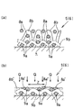
- FIG. 3 is a schematic diagram illustrating the structure of the double woven fabric layer.
- the double woven fabric layers 5 and 6 shown in the figure are double woven fabric layers made of PTFE fibers and fibers having higher tensile strength than PTFE fibers, and the PTFE fibers are arranged on the sliding surfaces 1a and 2a side of the upper and lower ridges.
- the double woven fabric layers 5 and 6 are fixed to the main body 4 as provided.
- Fibers with higher tensile strength than PTFE fibers include polyamides such as nylon 6, 6, nylon 6, nylon 4, 6, etc., polyethylene terephthalate (PET), polytrimethylene terephthalate, polybutylene terephthalate, polyethylene naphthalate, etc. Examples thereof include fibers such as polyester, para-aramid, meta-aramid, polyethylene, polypropylene, glass, carbon, polyphenylene sulfide (PPS), LCP, polyimide, and PEEK. Furthermore, fibers such as heat-sealing fibers, cotton, and wool may be applied.
- PET polyethylene terephthalate
- PPS polytrimethylene terephthalate
- polybutylene terephthalate polyethylene naphthalate
- fibers such as polyester, para-aramid, meta-aramid, polyethylene, polypropylene, glass, carbon, polyphenylene sulfide (PPS), LCP, polyimide, and PEEK.
- fibers such as
- the weft 9a of the PPS fiber is disposed on the main body 4 side of the sliding body 7, and the warp 9b of the PPS fiber is woven so as to be wound.
- a PTFE fiber weft 8a is arranged, and the PTFE fiber warp 8b is woven so as to wind the PTFE fiber weft 8a.
- the double weaving layers 5 and 6 are formed so that the weft 9a of the fiber is also woven so that the PTFE fibers are arranged on the sliding surfaces 1a and 2a of the upper and lower heels.
- These double woven fabric layers 5 and 6 are bonded and fixed via the main body 4 and the adhesive B.
- An epoxy resin adhesive can be applied as this adhesive. Since the PPS fiber has much better adhesion to the surface of the steel body 4 than the PTFE fiber, the double woven fabric layers 5 and 6 are applied to remove the PTFE fiber from the sliding surface 1a of the bag. There is an advantage that the PPS fiber is arranged on the main body 4 side of the sliding body 7 by being arranged on the 2a side.
- the PTFE fiber has a relatively low tensile strength
- the double woven fabric layers 5 and 6 are liable to be crushed when subjected to repeated vibrations (pressure sliding force) in a pressurized state.
- the crushed PTFE fiber has higher tensile strength than that, and therefore stays in the highly crushed PPS fiber so that at least a part of it faces the sliding surfaces 1a and 2a of the upper and lower ridges 1 and 2 Therefore, good slidability of the PTFE fiber can be enjoyed. This will be described with reference to FIGS. 4a and 4b.
- Fig. 4a is a schematic diagram showing a state before the double woven fabric layer is subjected to a load
- Fig. 4b is a schematic diagram showing a state where the double woven fabric layer is subjected to a pressure sliding force.
- the weft yarn 8a or warp of PTFE fiber is repeated with a certain number of repetitions. 8b is crushed. Then, as shown in FIG. 4b, the weft yarn 8a ′ of the PTFE fiber after being crushed and the warp yarn 8b ′ of the PTFE fiber after being crushed have high tensile strength, and therefore, the weft yarn 9a of the PPS fiber having good crush resistance, It will enter into the warp 9b of the PPS fiber.
- the weft yarn 8a 'and the warp yarn 8b' of the PTFE fiber after being crushed into the weft yarn 9a of the PPS fiber and the warp yarn 9b are partially slid between the upper and lower ridges 1,2. It faces the surfaces 1a and 2a, and therefore, even in the state of FIG. 4b, it is possible to enjoy the good slidability of the PTFE fiber. That is, the durability of the sliding seismic isolation device having desired seismic isolation performance can be improved by providing the sliding body 7 with the double woven fabric layers 5 and 6 of the illustrated form.
- the natural period of the sliding seismic isolation device is determined by the curvature radii of the upper and lower surfaces of the sliding body 7 (and the curvature radius of the sliding surface of the upper and lower ridges), and the natural period of the sliding seismic isolation device when the curvature radius is 2500 mm. T is 4.5 seconds, and the natural period T when the radius of curvature is 4500 mm is 6 seconds.
- the sliding body 7 is made of PTFE fibers and PPS fibers having higher tensile strength than the PTFE fibers on the upper and lower surfaces while realizing a surface pressure of 60 MPa with the steel sliding bodies 7.
- the present inventors manufactured the sliding seismic isolation device of the present invention (the standard value of the dynamic friction coefficient ⁇ is 0.045 to 0.05), and with this sliding seismic isolation device loaded with a load of 60 MPa, it is 400 mm at 20 ° C.
- the durability test was repeatedly performed at a speed of / sec.
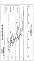
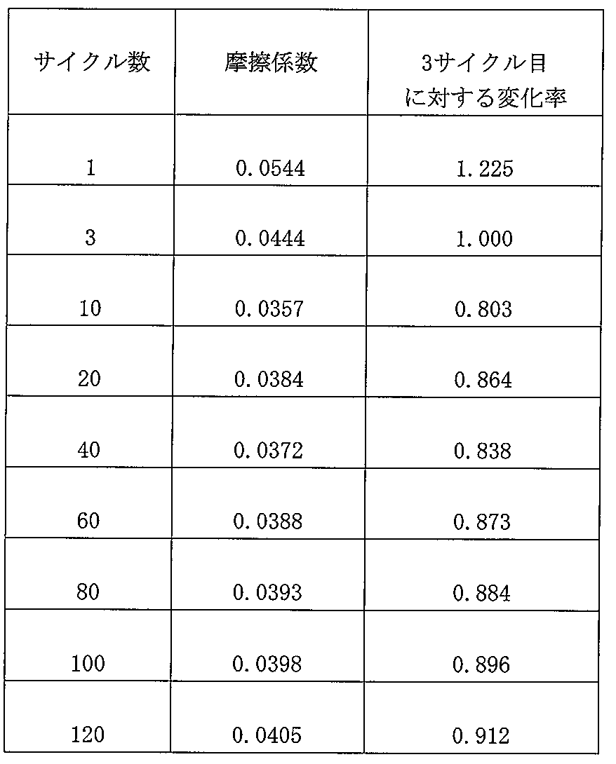
- Table 2 and FIG. 5 show the number of cycles up to 120 repetitions and the fluctuation (measured value) of the dynamic friction coefficient, which are the test results.
- L2 means level 2 ground motion
- shear force coefficient CB indicates the first floor shear force coefficient of the multi-layer structure model
- L3 means Level 3 ground motion, which is 1.5 times larger than Level 2 ground motion (the response displacement is a value that takes into account the margin). The response displacement was the response displacement during the L3 earthquake.
- the 1995 Hyogoken-Nanbu Earthquake JMA recording waveform is used as the seismic wave.
- the response displacement becomes 80 cm or more when the dynamic friction coefficient ⁇ is 0.02 or less, which is not preferable from the viewpoint of manufacturing cost.
- the dynamic friction coefficient ⁇ is in the range of 0.03 to 0.07
- the shear force coefficient CB is less than 0.2
- the dynamic friction coefficient ⁇ is preferably in the range of 0.03 to 0.07 for the 6.0-second and 8.0-second sliding seismic isolation devices.
- the response displacement ⁇ when the dynamic friction coefficient ⁇ is in the range of 0.04 to 0.05 when the natural period T is 4.5 seconds, the response displacement ⁇ can be controlled to around 60 cm, and the natural period T is 6 seconds.
- the response shear coefficient CB when the dynamic friction coefficient ⁇ is within the range of 0.03 to 0.05, the response shear coefficient CB can be less than 0.15, the response displacement ⁇ can be less than 70 cm, and the dynamic friction coefficient ⁇ when the natural period T is 8 seconds is 0.04 to 0.05. If it is within the range, the response shear coefficient CB can be made less than 0.15 and the response displacement ⁇ can be made less than 70 cm.
- SYMBOLS 1 Upper collar, 1a ... Sliding surface, 2 ... Lower collar, 2a ... Sliding surface, 3 ... Stopper, 4 ... Main body (sliding body main body), 4a ... Upper surface, 4b ... Lower surface, 5,6 ... Double fabric Layer, 7 ... sliding body, 8a ... PTFE fiber weft, 8a '... crushed PTFE fiber weft, 8b ... PTFE fiber warp, 8b' ... crushed PPS fiber warp, 9a ... PPS fiber Weft, 9b ... PPS fiber warp, 10 ... Sliding seismic isolation device
Landscapes
- Engineering & Computer Science (AREA)
- Architecture (AREA)
- Business, Economics & Management (AREA)
- Emergency Management (AREA)
- Environmental & Geological Engineering (AREA)
- Civil Engineering (AREA)
- Structural Engineering (AREA)
- General Engineering & Computer Science (AREA)
- Aviation & Aerospace Engineering (AREA)
- Mechanical Engineering (AREA)
- Physics & Mathematics (AREA)
- Acoustics & Sound (AREA)
- Vibration Prevention Devices (AREA)
- Buildings Adapted To Withstand Abnormal External Influences (AREA)
Abstract
Description
図1は本発明の滑り免震装置の実施の形態の縦断面図であり、図2は滑り免震装置の上沓を取り除いて斜め上から見た斜視図である。

本発明者等は、本発明の滑り免震装置(動摩擦係数μの基準値が0.045~0.05)を製作し、この滑り免震装置に対し、60MPaの荷重を載荷した状態で、20℃で400mm/secの速度で繰り返し耐久試験を実施した。試験結果である、繰り返し回数120回までの各サイクル数と動摩擦係数の変動(測定値)を以下の表2と図5に示す。
本発明者等はさらに、固有周期の異なる種々の滑り免震装置をコンピュータ内でモデル化し、各滑り免震装置に対して、動摩擦係数ごとのせん断力係数と応答変位を検証する実験をおこなった。実験結果を図6に示す。
Claims (6)
- 曲率を有する摺動面を備えた上沓および下沓と、
上沓と下沓の間で、それぞれの沓と接して曲率を有する上面および下面を備えた柱状で鋼製の摺動体と、から構成される滑り免震装置であって、
前記摺動体の前記上面と前記下面は、PTFE繊維と該PTFE繊維よりも引張強度の高い繊維からなる二重織物層を、PTFE繊維が前記上沓および下沓の摺動面側に配設されるようにして備えている滑り免震装置。 - 前記PTFE繊維よりも引張強度の高い繊維がPPS繊維である請求項1に記載の滑り免震装置。
- 摺動面上で摺動体が滑る際の固有周期Tが4.5秒~8秒の範囲にあり、かつ、摺動面と摺動体の動摩擦係数μが0.03~0.07の範囲にある請求項2に記載の滑り免震装置。
- 固有周期Tが4.5秒の際の動摩擦係数μは0.04~0.05の範囲にある請求項3に記載の滑り免震装置。
- 固有周期Tが6秒の際の動摩擦係数μは0.03~0.05の範囲にある請求項3に記載の滑り免震装置。
- 固有周期Tが8秒の際の動摩擦係数μは0.04~0.05の範囲にある請求項3に記載の滑り免震装置。
Priority Applications (5)
| Application Number | Priority Date | Filing Date | Title |
|---|---|---|---|
| US14/413,442 US9556609B2 (en) | 2013-07-25 | 2014-07-10 | Sliding seismic isolation device |
| EP14814684.8A EP2857717B1 (en) | 2013-07-25 | 2014-07-10 | Sliding seismic isolation device |
| MX2015001811A MX353514B (es) | 2013-07-25 | 2014-07-10 | Dispositivo de aislamiento sísmico deslizante. |
| CN201480001893.XA CN104487734B (zh) | 2013-07-25 | 2014-07-10 | 滑动免震装置 |
| PH12015500031A PH12015500031A1 (en) | 2013-07-25 | 2015-01-06 | Sliding seismic isolation device |
Applications Claiming Priority (2)
| Application Number | Priority Date | Filing Date | Title |
|---|---|---|---|
| JP2013154587A JP5521096B1 (ja) | 2013-07-25 | 2013-07-25 | 滑り免震装置 |
| JP2013-154587 | 2013-07-25 |
Publications (1)
| Publication Number | Publication Date |
|---|---|
| WO2015012115A1 true WO2015012115A1 (ja) | 2015-01-29 |
Family
ID=51031360
Family Applications (1)
| Application Number | Title | Priority Date | Filing Date |
|---|---|---|---|
| PCT/JP2014/068406 WO2015012115A1 (ja) | 2013-07-25 | 2014-07-10 | 滑り免震装置 |
Country Status (8)
| Country | Link |
|---|---|
| US (1) | US9556609B2 (ja) |
| EP (1) | EP2857717B1 (ja) |
| JP (1) | JP5521096B1 (ja) |
| CN (1) | CN104487734B (ja) |
| MX (1) | MX353514B (ja) |
| PH (1) | PH12015500031A1 (ja) |
| TW (1) | TWI639783B (ja) |
| WO (1) | WO2015012115A1 (ja) |
Families Citing this family (9)
| Publication number | Priority date | Publication date | Assignee | Title |
|---|---|---|---|---|
| JP6653615B2 (ja) * | 2016-04-19 | 2020-02-26 | 日鉄エンジニアリング株式会社 | 滑り免震装置 |
| JP6173639B1 (ja) * | 2017-05-10 | 2017-08-02 | 新日鉄住金エンジニアリング株式会社 | 滑り免震装置 |
| IT201700087916A1 (it) * | 2017-07-31 | 2019-01-31 | Anna Lucia Carla Andriulli | Dispositivo a scorrimento per costruzioni |
| JP6902972B2 (ja) * | 2017-09-14 | 2021-07-14 | オイレス工業株式会社 | 免震装置 |
| JP6349472B1 (ja) * | 2018-01-09 | 2018-06-27 | 新日鉄住金エンジニアリング株式会社 | 滑り免震装置用のスライダーと滑り免震装置 |
| KR20210101234A (ko) * | 2018-12-26 | 2021-08-18 | 도레이 카부시키가이샤 | 접동 포백 |
| JP6628923B1 (ja) * | 2019-05-23 | 2020-01-15 | 日鉄エンジニアリング株式会社 | 滑り免震装置 |
| JP6733026B1 (ja) * | 2019-11-27 | 2020-07-29 | 日鉄エンジニアリング株式会社 | 摺動体とその製作方法 |
| JP6762413B1 (ja) | 2019-12-20 | 2020-09-30 | 日鉄エンジニアリング株式会社 | 滑り免震装置 |
Citations (5)
| Publication number | Priority date | Publication date | Assignee | Title |
|---|---|---|---|---|
| JPH04101474U (ja) * | 1991-02-13 | 1992-09-02 | 大成建設株式会社 | 制振装置 |
| JP2002213101A (ja) * | 2001-01-19 | 2002-07-31 | Shimizu Corp | 免震装置および免震建物 |
| JP2008150724A (ja) * | 2006-12-15 | 2008-07-03 | Toray Ind Inc | 布帛 |
| WO2009054339A1 (ja) * | 2007-10-23 | 2009-04-30 | Tokyo Denki University | 免震装置及び免震構造物 |
| JP4848889B2 (ja) | 2006-08-21 | 2011-12-28 | オイレス工業株式会社 | 免震装置 |
Family Cites Families (22)
| Publication number | Priority date | Publication date | Assignee | Title |
|---|---|---|---|---|
| US3337222A (en) * | 1964-09-25 | 1967-08-22 | Watt V Smith | Quick acting submarine shaft seal |
| US4644714A (en) * | 1985-12-02 | 1987-02-24 | Earthquake Protection Systems, Inc. | Earthquake protective column support |
| JP3219197B2 (ja) | 1990-08-21 | 2001-10-15 | 株式会社小松製作所 | レーザ装置 |
| JP3337402B2 (ja) * | 1996-10-22 | 2002-10-21 | 三菱重工業株式会社 | 自己同調型制振装置 |
| US6021992A (en) * | 1997-06-23 | 2000-02-08 | Taichung Machinery Works Co., Ltd. | Passive vibration isolating system |
| TW428535U (en) * | 1999-12-23 | 2001-04-01 | Topkey Corp | Improved structure for fiber composite materials with multi-direction knitting |
| US6688051B2 (en) * | 2002-03-07 | 2004-02-10 | Chong-Shien Tsai | Structure of an anti-shock device |
| TW570983B (en) * | 2003-03-06 | 2004-01-11 | Rung-He Ke | Method for producing multi-layered leather and product thereof |
| NZ524611A (en) * | 2003-03-07 | 2005-09-30 | Robinson Seismic Ltd | Bearing assembly with sliding member between upper and lower bearing seats with elastic self-centering sleeve around seats |
| US7142803B2 (en) * | 2003-12-19 | 2006-11-28 | Ricoh Printing Systems, Ltd. | Fixing device and image forming apparatus |
| US20050241245A1 (en) * | 2004-04-29 | 2005-11-03 | Chong-Shien Tsai | Foundation shock eliminator |
| DE102005060375A1 (de) * | 2005-12-16 | 2007-06-21 | Steelpat Gmbh & Co. Kg | Gleitpendellager |
| US8484911B2 (en) * | 2006-05-12 | 2013-07-16 | Earthquake Protection Systems, Inc. | Sliding pendulum seismic isolation system |
| JP2008015072A (ja) * | 2006-07-04 | 2008-01-24 | Toppan Printing Co Ltd | カラーフィルタ用フォトマスク、カラーフィルタの製造方法、及びカラーフィルタ |
| TW200809057A (en) * | 2006-08-08 | 2008-02-16 | chong-xing Cai | Shock suppressor |
| US8011142B2 (en) * | 2007-02-06 | 2011-09-06 | Alga S.P.A. | Sliding pendulum seismic isolator |
| JP5352667B2 (ja) * | 2009-04-27 | 2013-11-27 | 新日鉄住金エンジニアリング株式会社 | 滑り構造、支承装置および免震構造物 |
| JP5859183B2 (ja) * | 2009-09-30 | 2016-02-10 | オイレス工業株式会社 | 摺動面材及び該摺動面材を備えた複層摺動部材 |
| IT1404858B1 (it) * | 2011-02-21 | 2013-12-09 | Milano Politecnico | Supporto anti-sismico. |
| JP6067307B2 (ja) * | 2012-10-01 | 2017-01-25 | オイレス工業株式会社 | 複層摺動部材の製造方法 |
| US8926180B2 (en) * | 2013-03-18 | 2015-01-06 | R. J. Watson, Inc. | Disc and spring isolation bearing |
| US9175468B1 (en) * | 2014-07-09 | 2015-11-03 | Chong-Shien Tsai | Shock suppressor |
-
2013
- 2013-07-25 JP JP2013154587A patent/JP5521096B1/ja active Active
-
2014
- 2014-07-10 WO PCT/JP2014/068406 patent/WO2015012115A1/ja active Application Filing
- 2014-07-10 EP EP14814684.8A patent/EP2857717B1/en active Active
- 2014-07-10 TW TW103123841A patent/TWI639783B/zh active
- 2014-07-10 MX MX2015001811A patent/MX353514B/es active IP Right Grant
- 2014-07-10 US US14/413,442 patent/US9556609B2/en active Active
- 2014-07-10 CN CN201480001893.XA patent/CN104487734B/zh active Active
-
2015
- 2015-01-06 PH PH12015500031A patent/PH12015500031A1/en unknown
Patent Citations (5)
| Publication number | Priority date | Publication date | Assignee | Title |
|---|---|---|---|---|
| JPH04101474U (ja) * | 1991-02-13 | 1992-09-02 | 大成建設株式会社 | 制振装置 |
| JP2002213101A (ja) * | 2001-01-19 | 2002-07-31 | Shimizu Corp | 免震装置および免震建物 |
| JP4848889B2 (ja) | 2006-08-21 | 2011-12-28 | オイレス工業株式会社 | 免震装置 |
| JP2008150724A (ja) * | 2006-12-15 | 2008-07-03 | Toray Ind Inc | 布帛 |
| WO2009054339A1 (ja) * | 2007-10-23 | 2009-04-30 | Tokyo Denki University | 免震装置及び免震構造物 |
Non-Patent Citations (1)
| Title |
|---|
| See also references of EP2857717A4 * |
Also Published As
| Publication number | Publication date |
|---|---|
| EP2857717B1 (en) | 2016-10-05 |
| MX2015001811A (es) | 2015-05-28 |
| TW201512560A (zh) | 2015-04-01 |
| CN104487734A (zh) | 2015-04-01 |
| CN104487734B (zh) | 2016-07-06 |
| TWI639783B (zh) | 2018-11-01 |
| PH12015500031B1 (en) | 2015-02-23 |
| PH12015500031A1 (en) | 2015-02-23 |
| MX353514B (es) | 2018-01-17 |
| US9556609B2 (en) | 2017-01-31 |
| JP5521096B1 (ja) | 2014-06-11 |
| US20160215495A1 (en) | 2016-07-28 |
| JP2015025486A (ja) | 2015-02-05 |
| EP2857717A1 (en) | 2015-04-08 |
| EP2857717A4 (en) | 2015-08-26 |
Similar Documents
| Publication | Publication Date | Title |
|---|---|---|
| JP5521096B1 (ja) | 滑り免震装置 | |
| WO2020006850A1 (zh) | 一种抗拔型三维橡胶摩擦摆隔震支座 | |
| EP4290027A3 (en) | Insulation board with improved performance | |
| JP6173639B1 (ja) | 滑り免震装置 | |
| KR102048508B1 (ko) | 3축 섬유 강화된 복합 라미네이트 | |
| RU2012144030A (ru) | Способ изготовления ламинатных материалов | |
| JP2016520458A (ja) | 床又は壁装部品用の複合パネル及びそのようなパネルの製造方法 | |
| Hedayati Dezfuli et al. | Performance of carbon fiber‐reinforced elastomeric isolators manufactured in a simplified process: experimental investigations | |
| JP2023126818A (ja) | 免震アイソレータ及び減衰デバイス | |
| RU2518519C2 (ru) | Панель из слоистых композиционных материалов | |
| JP5408672B2 (ja) | 構造物用高支圧支承装置 | |
| JP6349472B1 (ja) | 滑り免震装置用のスライダーと滑り免震装置 | |
| JP2016539303A5 (ja) | ||
| JP5779003B2 (ja) | 鋼構造物の補強方法及び鋼構造物補強用積層材 | |
| Biggerstaff et al. | Damping performance of cocured composite laminates with embedded viscoelastic layers | |
| TW201738434A (zh) | 橋梁用之防震支承及使用其之橋梁 | |
| JP2013217483A (ja) | 積層ゴム支承体 | |
| JP6628923B1 (ja) | 滑り免震装置 | |
| JP2006200158A5 (ja) | ||
| KR20220142910A (ko) | 굽힘 변형 측정이 가능한 복합재, 이를 포함하는 스프링 및 그 제조방법 | |
| JP6735319B2 (ja) | シャフト | |
| JP5524683B2 (ja) | ゴム支承体 | |
| US20160061267A1 (en) | Self-lubricating articulation element made from a composite material and operating under high dynamic loadings | |
| JP2022037508A (ja) | 滑り免震装置 | |
| JP2009228850A (ja) | 免震用積層ゴム |
Legal Events
| Date | Code | Title | Description |
|---|---|---|---|
| REEP | Request for entry into the european phase |
Ref document number: 2014814684 Country of ref document: EP |
|
| WWE | Wipo information: entry into national phase |
Ref document number: 2014814684 Country of ref document: EP |
|
| WWE | Wipo information: entry into national phase |
Ref document number: 12015500031 Country of ref document: PH |
|
| WWE | Wipo information: entry into national phase |
Ref document number: 14413442 Country of ref document: US |
|
| WWE | Wipo information: entry into national phase |
Ref document number: IDP00201500726 Country of ref document: ID |
|
| WWE | Wipo information: entry into national phase |
Ref document number: MX/A/2015/001811 Country of ref document: MX |
|
| 121 | Ep: the epo has been informed by wipo that ep was designated in this application |
Ref document number: 14814684 Country of ref document: EP Kind code of ref document: A1 |
|
| NENP | Non-entry into the national phase |
Ref country code: DE |