WO2015012076A1 - 像ブレ補正装置及び撮像装置 - Google Patents
像ブレ補正装置及び撮像装置 Download PDFInfo
- Publication number
- WO2015012076A1 WO2015012076A1 PCT/JP2014/067614 JP2014067614W WO2015012076A1 WO 2015012076 A1 WO2015012076 A1 WO 2015012076A1 JP 2014067614 W JP2014067614 W JP 2014067614W WO 2015012076 A1 WO2015012076 A1 WO 2015012076A1
- Authority
- WO
- WIPO (PCT)
- Prior art keywords
- image
- unit
- shake
- amount
- correction
- Prior art date
- Legal status (The legal status is an assumption and is not a legal conclusion. Google has not performed a legal analysis and makes no representation as to the accuracy of the status listed.)
- Ceased
Links
Images


Classifications
-
- G—PHYSICS
- G03—PHOTOGRAPHY; CINEMATOGRAPHY; ANALOGOUS TECHNIQUES USING WAVES OTHER THAN OPTICAL WAVES; ELECTROGRAPHY; HOLOGRAPHY
- G03B—APPARATUS OR ARRANGEMENTS FOR TAKING PHOTOGRAPHS OR FOR PROJECTING OR VIEWING THEM; APPARATUS OR ARRANGEMENTS EMPLOYING ANALOGOUS TECHNIQUES USING WAVES OTHER THAN OPTICAL WAVES; ACCESSORIES THEREFOR
- G03B5/00—Adjustment of optical system relative to image or object surface other than for focusing
-
- H—ELECTRICITY
- H04—ELECTRIC COMMUNICATION TECHNIQUE
- H04N—PICTORIAL COMMUNICATION, e.g. TELEVISION
- H04N23/00—Cameras or camera modules comprising electronic image sensors; Control thereof
- H04N23/60—Control of cameras or camera modules
- H04N23/68—Control of cameras or camera modules for stable pick-up of the scene, e.g. compensating for camera body vibrations
- H04N23/681—Motion detection
- H04N23/6812—Motion detection based on additional sensors, e.g. acceleration sensors
-
- H—ELECTRICITY
- H04—ELECTRIC COMMUNICATION TECHNIQUE
- H04N—PICTORIAL COMMUNICATION, e.g. TELEVISION
- H04N23/00—Cameras or camera modules comprising electronic image sensors; Control thereof
- H04N23/60—Control of cameras or camera modules
- H04N23/68—Control of cameras or camera modules for stable pick-up of the scene, e.g. compensating for camera body vibrations
- H04N23/682—Vibration or motion blur correction
- H04N23/685—Vibration or motion blur correction performed by mechanical compensation
- H04N23/687—Vibration or motion blur correction performed by mechanical compensation by shifting the lens or sensor position
-
- G—PHYSICS
- G03—PHOTOGRAPHY; CINEMATOGRAPHY; ANALOGOUS TECHNIQUES USING WAVES OTHER THAN OPTICAL WAVES; ELECTROGRAPHY; HOLOGRAPHY
- G03B—APPARATUS OR ARRANGEMENTS FOR TAKING PHOTOGRAPHS OR FOR PROJECTING OR VIEWING THEM; APPARATUS OR ARRANGEMENTS EMPLOYING ANALOGOUS TECHNIQUES USING WAVES OTHER THAN OPTICAL WAVES; ACCESSORIES THEREFOR
- G03B2205/00—Adjustment of optical system relative to image or object surface other than for focusing
- G03B2205/0007—Movement of one or more optical elements for control of motion blur
- G03B2205/0038—Movement of one or more optical elements for control of motion blur by displacing the image plane with respect to the optical axis
Definitions
- the present invention relates to an image shake correction apparatus that corrects image quality deterioration that occurs based on an image shake caused by camera shake at the time of shooting, and an imaging apparatus equipped with the image shake correction apparatus.
- the correction performance of the camera shake correction function is indicated by the value of the shutter speed (exposure time) capable of correcting the image shake. This is because the camera shake correction function is performed with the shutter speed (also referred to as the camera shake limit shutter speed) at which the effect of the image blur caused by the camera shake starts to be seen in images captured without executing the camera shake correction function. This is represented by the ratio to the shutter speed at which the effects of image blurring due to camera shake begin to appear in an image.
- the mechanism of camera shake correction that is conventionally known is, for example, as follows. First, an image blur amount (image plane movement amount) based on a change in the posture of the camera body due to camera shake is detected by a gyro sensor or the like corresponding to the camera shake detection unit. Then, the image blur correction amount is calculated from the image blur amount detected by the camera shake detection unit. Further, the image shake correction unit performing the image shake correction moves the optical system or the imaging device in the direction to cancel the image shake amount detected by the camera shake detection unit based on the calculated image shake correction amount. Thereby, the image blurring generated on the imaging surface is suppressed.
- the correction performance of the camera shake correction function tends to decrease as the focal length of the photographing optical system of the camera increases. This is because, as the focal length increases, the amount of movement of the image plane generated by camera shake increases, for example, it is necessary to make the movement of the optical system or the image sensor by the image blur correction unit respond faster. This is because the conditions for correcting the image blur become severer in accordance with the amount of movement.
- the influence of the above-mentioned response delay is also greater in the case of shooting in the telephoto range where the focal length is long, in the case of close-up shooting where the shooting magnification is large, and when the camera shake frequency of the photographer is high, etc. Become.
- an angular velocity sensor for detecting a camera shake for detecting a camera shake
- a high pass filter for attenuating a blur signal having a frequency lower than a first breakpoint frequency with respect to the detected blur signal A phase compensation filter that compensates for a phase shift between the signal processed by the high-pass filter and the phase of the signal before being processed, and imaging based on the blur signal whose phase shift is compensated by the phase compensation filter
- a shake correction unit for correcting an image shake of the apparatus, and the phase compensation filter changes the phase so as to cancel the phase shift caused by the high-pass filter, thereby preventing the deterioration of the correction performance due to the phase shift It is like that.
- the angular velocity output of the gyro sensor is read (sampled) at a constant cycle, time integral calculation is performed to calculate an integral value of angular velocity, and the calculated integral value and the previous integral value
- time integral calculation is performed to calculate an integral value of angular velocity
- the calculated integral value and the previous integral value In order to obtain the shift amount of the shift lens that can cancel the inclination of the optical axis of the lens based on the variation and the delay time and control time determined by the shake correction module, The added value is calculated, and the value obtained by adding the added value to the current integrated value is used to calculate and drive a control value for moving the shift lens, thereby obtaining a photographed image free from blurring.
- the method disclosed in the above-mentioned Patent Document 1 performs phase adjustment with respect to the phase shift by the high pass filter, and the performance deterioration with the delay time due to the calculation of the correction amount and the response time with the driver. Not considered about. Also, in the phase compensation filter, only phase compensation is performed for a specific frequency range, so for an image blur signal that occurs in a camera shake state of a camera, for those including various frequency components, It can not be said that the phase shift (delay) is completely compensated.
- the change amount of the correction amount obtained by integrating the angular velocity that is, the change amount based on the delay time from the immediately preceding angular velocity is added to the correction amount.
- a correction amount with a small calculation error can be obtained, but in a section in which the change in angular velocity is large, a correction amount with a large calculation error may be obtained.
- the amount of change to be added is calculated by linear approximation, if the above-mentioned delay time becomes long, the error of the added value may increase, which may lead to erroneous correction.
- the present invention has been made focusing on the above problem, and the delay time is offset by predicting the state of the camera shake after the delay time caused by the camera shake correction with high accuracy by a simple calculation, and high correction performance is achieved. It is an object of the present invention to provide a camera shake correction device for realizing the above and an imaging device equipped with the same.
- a first aspect of the present invention is an image shake correction apparatus for correcting an image shake based on a change in posture of an image pickup apparatus, comprising: an optical system for forming an object image; and an object image formed by the optical system
- a shake correction unit that corrects image blur by moving an imaging element to be imaged and a lens included in the optical system in a direction perpendicular to the optical axis or moving the imaging element onto an imaging surface
- a shake detection unit that detects an amount of change in posture of the imaging device; a holding unit that holds three or more amounts of change in posture detected at different times by the shake detection unit; and 3 held by the holding unit
- a prediction unit for calculating a predicted value of the posture change amount after a predetermined time based on an approximation function based on time change of the posture change amount based on at least one posture change amount, and a predicted value calculated by the prediction unit Calculate the amount of image blur based on Image blur correction apparatus, comprising: a blur amount calculation unit; and a drive control unit that calculates
- a second aspect of the present invention is an image shake correction apparatus for correcting an image shake based on a change in posture of an image pickup apparatus, comprising: an optical system for forming an object image; and an object image formed by the optical system
- a shake correction unit that corrects image blur by moving an imaging element to be imaged and a lens included in the optical system in a direction perpendicular to the optical axis or moving the imaging element onto an imaging surface
- a shake detection unit that detects an image plane movement amount based on the posture change of the imaging device; a holding unit that holds three or more image plane movement amounts detected at different times by the shake detection unit;
- a prediction unit that calculates a predicted value of the image plane movement amount after a predetermined time based on an approximation function based on a time change of the image plane movement amount based on three or more image plane movement amounts held in the holding unit; , Based on the predicted value calculated by the prediction unit ,
- the three or more posture change amounts or image plane movement amounts used when the prediction unit calculates the approximation function is a predetermined time before the current time.
- the image shake correction apparatus wherein the three or more posture change amounts or the image plane movement amounts are detected by the shake detection unit during the period.
- the predicted value calculated by the prediction unit is detected by the shake detection unit until correction by the shake correction unit is performed.
- An image blur correction device is provided, which is a value after a time corresponding to the processing time of.
- At least three posture change amounts or image plane movement amounts used by the prediction unit in calculating the approximate function are determined by the shake detection unit.
- An image blur correction device is provided that includes the latest amount of posture change or amount of image plane movement detected.
- the blur detection unit detects three or more posture change amounts or image plane movement amounts used when the prediction unit calculates the approximate function.
- the image blur correction device is provided, wherein the time interval of the given time is a power of 2 time.
- a seventh aspect of the present invention provides an imaging device provided with the image blur correction device of any one of the first to sixth aspects.
- a camera shake correction device and a camera shake correction device for offseting the delay time and realizing high correction performance by predicting the state of the camera shake after the delay time caused by the camera shake correction with high accuracy by a simple calculation.
- FIG. 7 is a diagram showing an example of the relationship between the time change of the input angular velocity and the time change of the predicted angular velocity in the angular velocity prediction unit according to the first embodiment.
- An image shake correction apparatus is an apparatus for correcting an image shake based on a change in posture of an imaging device.
- the concept of image shake correction performed by the image shake correction device according to each embodiment will be described with reference to FIGS. 1 and 2.
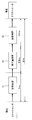
- FIG. 1 is a diagram showing an example of a flow of control relating to image blur correction and processing time.
- a low pass for removing noise with respect to an angular velocity (angular velocity corresponding to camera shake) detected by an angular velocity sensor such as a gyro sensor Signal processing such as filter processing and high pass filter processing for removing a DC component is performed (S1).
- an arithmetic operation for obtaining a correction amount by performing time integration on the angular velocity signal-processed in S1 is performed (S2).
- drive control is performed to move the optical system or the imaging device by the actuator based on the correction amount obtained by the calculation in S2 (S3).
- Such control flow corrects image blur caused by camera shake.
- the delay time is made substantially zero by predicting the state of camera shake after the delay time, and higher correction performance is realized. .
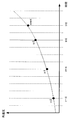
- FIG. 2 is a diagram for explaining an example of a method of predicting the state of camera shake after the delay time, and is also a graph showing an example of temporal change in angular velocity.
- the delay time is 2 ms
- a method of predicting the state of camera shake after 2 ms will be described.
- the detection of the angular velocity and the calculation of the correction amount are performed in a cycle of 1 ms.
- the time when t becomes negative indicates the time when it is past with respect to the reference time
- the time when t becomes positive is the reference It shows the time to be the future with respect to the time.
- the approximate expression of the quadratic approximate curve can be obtained from the three angular velocities ⁇ 0 , ⁇ 1 , and ⁇ 2 by the matrix equation of the following expression (1).
- t 0 is the time when ⁇ 0 is detected
- t 1 is the time when ⁇ 1 is detected
- t 2 is the time when ⁇ 2 is detected.
- Equation (3) (1 / detA) adjA equation (3)
- DetA is a determinant corresponding to the matrix A
- adjA is a cofactor matrix of the matrix A.
- the second-order approximation coefficients a, b, c are based on the inverse matrix A ⁇ 1 , It can be calculated by the following equations (4) and (5).
- equation (4) becomes equation (6).
- detA 128 expression (6)
- equation (5) can be simplified as in the following equations (7), (8) and (9).
- the time interval at which the angular velocities ⁇ 0 , ⁇ 1 and ⁇ 2 are detected becomes a power of 2 at time intervals of t 0 , t 1 and t 2
- the division in equation (10) can be replaced by a shift operation. Therefore, the calculation load can be suppressed, and an increase in delay time caused by the calculation can be suppressed.
- the approximate expression is not limited to this.
- the prediction is performed using an approximation of a linear polynomial, although the calculation load of the correction amount decreases and the calculation time is expected to decrease, it is essential that the predicted value changes monotonously in time. Therefore, it should be noted that the time for which the error can be reduced and the time for prediction can be reduced and the application is limited.
- an example of predicting the state of camera shake by predicting the angular velocity is shown, but instead of the angular velocity, the image plane movement amount (the movement amount of the subject image formed on the imaging surface) is made similar. It is also possible to predict the state of camera shake by prediction.
- an acceleration sensor is added, the velocity is similarly predicted based on the output of the acceleration sensor, and the angular velocity or image plane movement amount predicted based on the output of the angular velocity sensor and the output of the acceleration sensor The state of camera shake may be predicted by combining the predicted speed.
- an acceleration sensor may be provided instead of the angular velocity sensor, and the state of camera shake may be predicted by similarly predicting the velocity based on the output of the acceleration sensor.
- the state of camera shake is predicted by predicting the angular velocity based on the output of the angular velocity sensor
- the image plane movement amount is based on the output of the angular velocity sensor
- the state of camera shake is predicted by predicting the following: the angular velocity predicted based on the output of the angular velocity sensor and the velocity predicted based on the output of the acceleration sensor
- the state of camera shake is predicted in combination is shown in the third embodiment.
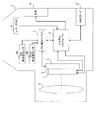
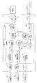
- FIG. 3 is a view showing a configuration example of a camera including the image shake correction device according to the first embodiment of the present invention.
- the camera 1 includes an optical system 2, a focal plane shutter (hereinafter simply referred to as a shutter) 3, an imaging device 4, a drive unit 5, a system controller 6, and a shake correction microcomputer 7. It includes an angular velocity sensor 8, a release switch (SW) 9, an EVF (Electronic View Finder) 10, and a memory card 11.
- the camera 1 is an example of an imaging device.
- the optical system 2 forms an image of a subject. More specifically, the optical system 2 causes a light flux from the external optical axis direction to be formed as an object image on the imaging surface of the imaging device 4.
- the shutter 3 performs an opening / closing operation on the front surface of the imaging device 4 under the control of the system controller 6 to bring the imaging device 4 into an exposure state or a light blocking state.
- the imaging device 4 captures an object image formed on the imaging surface by the optical system 2 under the control of the system controller 6 and converts it into an electrical signal.
- the converted electrical signal is read out as a video signal by the system controller 6.
- the exposure control is performed by the shutter 3 which is a mechanical shutter.
- the exposure control is performed by a so-called electronic shutter which performs exposure control by giving an imaging control signal to the imaging element 4 You may do so.
- the system controller 6 performs various controls related to the functions of the entire camera, in addition to the above-described readout of the video signal. For example, control is performed to convert a video signal read out from the image sensor 4 into a format that can be displayed on the EVF 10 and output the converted signal. Further, for example, control is performed to record a video signal read out at the time of shooting in the memory card 11 as a shot image. This control is performed according to the detection of the release SW 9. Further, for example, communication with the shake correction microcomputer 7 is performed to perform centralized control.
- the EVF 10 is a display device such as a liquid crystal display device, and displays, for example, an image of the video signal output from the system controller 6 so that a photographer can visually recognize the video signal.
- the release switch 9 is an operation unit used when the user performs a shooting operation. The release switch 9 distinguishes and detects an operation state of two steps of a half press operation (1st release) and a full press operation (2nd release), and outputs a signal according to the detection result to the system controller 6.
- the memory card 11 is a non-volatile memory that can be attached to and detached from the camera 1 and stores a photographed image and the like.
- the angular velocity sensor 8 (8a, 8b) is a sensor (for example, a gyro sensor) that detects rotational movement accompanying a change in posture of the camera, detects temporal change in angle during rotational movement as angular velocity, and outputs it to the shake correction microcomputer 7 Do.
- the angular velocity sensor 8 a is a sensor that detects the rotational motion of the camera 1 in the Yaw direction
- the angular velocity sensor 8 b is a sensor that detects the rotational motion of the camera 1 in the pitch direction.
- the angular velocity sensor 8 is an example of a blur detection unit that detects the amount of change in posture of the imaging device.
- the shake correction microcomputer 7 calculates the shake amount as the movement amount of the subject image formed on the imaging device 4 from the output of the angular velocity sensor 8 (8a, 8b), and calculates the shake amount.
- a control signal for moving the image pickup device 4 in the canceling direction is output to the drive unit 5.
- the control signal also takes into consideration the position of the image sensor 4 in accordance with the position detection signal output from the drive unit 5.
- the driving unit 5 supports the imaging device 4 and under the control of the motion compensation microcomputer 7 (according to a control signal from the motion compensation microcomputer 7), the imaging device 4 in the X direction (horizontal direction) and the Y direction (horizontal direction). Vertically). As a result, the imaging element 4 moves in the direction to cancel the amount of blurring on the imaging surface, and blurring that occurs in the photographed image can be prevented. Further, the drive unit 5 detects the position of the imaging device 4 and outputs the position detection signal to the shake correction microcomputer 7.
- the driving unit 5 is an example of a shake correction unit that corrects an image shake by moving the imaging element 4 on the imaging surface (on the imaging surface).
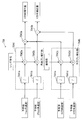
- FIG. 4 is a view showing an example of the configuration of the shake correction microcomputer 7.
- the shake correction microcomputer 7 includes a control unit 70, signal processing units 71 (71a and 71b), a driver 72, an ADC (Analog / digital converter) 73, and an SIO (Serial Input / Output). 74).
- the control unit 70 further includes a reference calculation unit 701 (701a, 701b), a subtraction unit 702 (702a, 702b), an angular velocity prediction unit 703 (703a, 703b), a correction amount calculation unit 704, and drive control.
- a unit 705 and a communication unit 706 are included.
- the signal processing unit 71a performs signal processing including analog / digital conversion processing, low pass filter processing, and high pass filter processing on an analog signal that is an output signal (angular velocity detection signal) of the angular velocity sensor 8a.
- the signal processing unit 71b performs signal processing including analog / digital conversion processing, low pass filter processing, and high pass filter processing on an analog signal that is an output signal (angular velocity detection signal) of the angular velocity sensor 8b.
- Signal processing in each of the signal processing units 71a and 71b is performed at a cycle corresponding to a predetermined sampling rate. For example, when the sampling rate is 1 kHz, it is performed in a 1 ms cycle.
- the signal processing performed by each of the signal processing units 71a and 71b may be, for example, only analog / digital conversion processing.
- the reference calculation unit 701a calculates a reference value based on the output signal of the signal processing unit 71a. This reference value is based on the output signal of the angular velocity sensor 8a when the camera 1 is in a stationary state. More specifically, an average value (time average value) of angular velocity values detected during a predetermined time in which the camera 1 is in a stationary state is calculated and used as a reference value. However, the method of calculating the reference value is not limited to this, and any method may be used as long as a reference value with a small error can be calculated. Similarly, the reference calculation unit 701b calculates a reference value based on the output signal of the signal processing unit 71b.
- the subtraction unit 702a subtracts the output signal (reference value) of the reference calculation unit 701a from the output signal (angular velocity) of the signal processing unit 71a, and outputs a signal of angular velocity having a sign.
- the subtracting unit 702b subtracts the output signal (reference value) of the reference calculating unit 701b from the output signal (angular velocity) of the signal processing unit 71b, and outputs a signal of an angular velocity having a sign.
- the sign of the angular velocity can be treated as the rotational direction of the detected angular velocity.
- the angular velocity prediction unit 703a predicts (predicts) a predicted value of the angular velocity (angular velocity in the Yaw direction) after a predetermined time based on an approximation function based on time change of angular velocity. (Also referred to as angular velocity).
- the angular velocity prediction unit 703b predicts the angular velocity (angular velocity in the pitch direction) after a predetermined time based on an output signal (also referred to as input angular velocity) of the subtraction unit 702b based on an approximation function based on time change of angular velocity. Calculate a value (also referred to as a predicted angular velocity).
- the predetermined time is, for example, a time corresponding to a processing time from the detection of the angular velocity to the correction of the image blur.
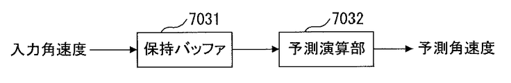
- the angular velocity prediction units 703a and 703b each include a holding buffer 7031 and a prediction calculation unit 7032.
- the angular velocity prediction unit 703a will be described as an example.
- the holding buffer 7031 holds three or more input angular velocities corresponding to three or more angular velocities detected at different times by the angular velocity sensor 8a.
- the holding buffer 7031 holds, for example, three or more input angular velocities corresponding to three or more angular velocities detected by the angular velocity sensor 8a a predetermined time before the current time.
- the three or more input angular velocities are, for example, nine corresponding to nine angular velocities detected in a 1 ms cycle between the time when the latest angular velocity was detected and the time 8 ms before the time. It is an input angular velocity, and is updated every 1 ms period.
- the holding buffer 7031 is an example of a holding unit that holds three or more posture change amounts detected at different times by the shake detection unit.
- the prediction calculation unit 7032 calculates a predicted value (prediction of angular velocity in the Yaw direction) after a predetermined time based on an approximation function based on time change of angular velocity based on three or more input angular velocity held in the holding buffer 7031. Calculate angular velocity). For example, on the basis of the three input angular velocities ⁇ 0 , ⁇ 1 , and ⁇ 2 held in the holding buffer 7031, for example, the prediction calculation unit 7032 determines the delay time based on the equation (10) which is an approximation function based on the time change of the angular velocity. The predicted value ⁇ est of the angular velocity after 2 ms corresponding to is calculated.
- the input angular velocity ⁇ 0 is the input angular velocity corresponding to the latest angular velocity
- the input angular velocity ⁇ 1 is the input angular velocity corresponding to the angular velocity 4 ms (four cycles) before the time when the latest angular velocity is detected
- the input angular velocity omega 2 is an input angular velocity latest angular velocity corresponding to 8 ms (8 cycles) before the angular velocity with respect to time are detected.
- the correction amount calculation unit 704 calculates the correction amount (image blur amount) in the X direction based on the predicted value calculated by the angular velocity prediction unit 703a, and based on the predicted value calculated by the angular velocity prediction unit 703b. A correction amount (image blur amount) in the Y direction is calculated. More specifically, the correction amount calculation unit 704 has, for example, a configuration of an angle shake correction unit 7044 included in a correction amount calculation unit 704 shown in FIG.
- the angular velocity prediction unit 703a predicted value By calculating the correction amount in the X direction (image blur amount) by performing multiplication operation using the value obtained by temporally integrating) and parameters (focal length, image magnification) based on lens characteristics, and angular velocity prediction Correction amount in Y direction (image blur amount) by performing multiplication operation using values obtained by time integrating the output signal (predicted value) of the unit 703b and parameters (focal length, image magnification) based on lens characteristics Calculate).
- the drive control unit 705 calculates the movement amount of the image sensor 4 in the X direction by the drive unit 5 based on the correction amount in the X direction (image blur amount) calculated by the correction amount calculation unit 704, and calculates the correction amount. Based on the correction amount in the Y direction (image blur amount) calculated by the unit 704, the movement amount of the image sensor 4 in the Y direction by the drive unit 5 is calculated. More specifically, the drive control unit 705 determines the movement target position of the image sensor 4 by the drive unit 5 based on the correction amount in the X direction and the correction amount in the Y direction calculated by the correction amount calculation unit 704, for example.
- the drive unit 5 Based on the movement target position and the signal corresponding to the position detection signal output from the drive unit 5, the drive unit 5 outputs a drive signal for moving the imaging element 4 to the target position while performing feedback control. Do.
- the drive control unit 705 controls the movement of the imaging device 4 by the closed loop control in this manner, for example, the movement of the imaging device 4 may be controlled by the open loop control.
- the driver 72 converts the drive signal from the drive control unit 705 into a signal form for driving the drive unit 5 and outputs it. As a result, movement of the image sensor 4 is performed by the drive unit 5 in accordance with the input drive signal, and as a result, blurring that occurs in a photographed image is prevented.
- the ADC 73 converts an analog signal which is a position detection signal output from the drive unit 5 into a digital signal, and outputs the digital signal to the drive control unit 705.
- the communication unit 706 controls the SIO 74, which is a serial input / output interface, to perform communication (for example, transmission / reception of commands, etc.) with an external device (system controller 6).
- the blur correction microcomputer 7 described with reference to FIGS. 4 and 5 predicts the angular velocity after a predetermined time (for example, 2 ms), and corrects the image blur based on the prediction.
- a predetermined time for example, 2 ms
- FIG. 6 is a diagram showing an example of the relationship between the time change of the input angular velocity and the time change of the predicted angular velocity in the angular velocity prediction unit 703 (703a or 703b).
- the input angular velocity at that time is the input angular velocity ⁇ 0 corresponding to the latest angular velocity
- the predicted angular velocity at any time is an angular velocity 4 ms (four cycles) before the time when the latest angular velocity is detected.
- the temporal change of the predicted angular velocity is advanced by 2 ms with respect to the temporal change of the input angular velocity. If the prediction error, which is the difference between the predicted angular velocity and the angular velocity after 2 ms, is sufficiently smaller than the difference between the current angular velocity and the angular velocity after 2 ms, it is obvious that the decrease in correction performance due to delay is small. It is.
- the angular velocity after a predetermined time (for example, 2 ms) is predicted by a simple calculation, and the correction amount is calculated based on the predicted value. Since the increase can be suppressed and the delay time from the detection of the shake to the correction can be shortened, it is possible to prevent the deterioration of the correction performance due to the response delay.
- the camera including the image shake correction apparatus according to the second embodiment of the present invention differs from the camera including the image shake correction apparatus according to the first embodiment in the configuration and operation of the shake correction microcomputer. Therefore, in the description of the camera including the image shake correction device according to the present embodiment, the differences will be mainly described. In the present embodiment, the same components as the components described in the first embodiment will be described with the same reference numerals.
- FIG. 7 is a view showing a configuration example of the shake correction microcomputer 7 included in the camera 1 including the image shake correction device according to the present embodiment.
- the shake correction microcomputer 7 shown in FIG. 7 differs from the shake correction microcomputer 7 shown in FIG. 4 in the following point.
- the angular velocity prediction unit 703 (703a, 703b) and the correction amount calculation unit 704 included in the shake correction microcomputer 7 shown in FIG. This is a point replaced by the prediction unit 708.
- the correction amount calculation unit 707 has, for example, the configuration of an angle shake correction unit 7044 included in a correction amount calculation unit 704 shown in FIG. 12 described later, and integrates the output signal (angular velocity) of the subtraction unit 702a with time.
- the correction amount (image plane movement amount) in the X direction is calculated, and the output signal of the subtraction unit 702b (
- a correction amount (image plane movement amount) in the Y direction is calculated by performing multiplication operation using a value obtained by temporally integrating the angular velocity) and parameters (focal length, image magnification) based on the lens characteristics.
- the correction amount calculation unit 707 is an example of a shake detection unit that detects an image plane movement amount based on a change in posture of the imaging device.
- the correction amount prediction unit 708 calculates the correction amount in the X direction after a predetermined time based on an approximation function based on time change of the correction amount
- a predicted value also referred to as a predicted correction amount
- the predetermined time is, for example, a time corresponding to a processing time from the detection of the angular velocity or the calculation of the image plane movement amount to the correction of the image blur.
- the correction amount prediction unit 708 includes a holding buffer 7081 and a prediction calculation unit 7082 as shown in FIG. 8 for each of the X direction and the Y direction.
- the holding buffer 7081 and the prediction calculation unit 7082 in the X direction will be described as an example.
- the holding buffer 7081 holds three or more correction amounts in the X direction calculated by the correction amount calculation unit 707 at different times.
- the holding buffer 7081 holds, for example, three or more correction amounts in the X direction calculated by the correction amount calculation unit 707 during a predetermined time before the current time.
- the three or more correction amounts in the X direction are, for example, 9 calculated in 1 ms cycles between the time when the latest correction amount in the X direction is calculated and the time 8 ms before the time. Correction amount in the X direction and updated every 1 ms period.
- the holding buffer 7081 is an example of a holding unit that holds three or more image plane movement amounts detected at different times by the shake detection unit.
- the prediction calculation unit 7082 is a predicted value of the correction amount in the X direction after a predetermined time based on an approximation function based on a time change of the correction amount based on the three or more correction amounts in the X direction held in the holding buffer 7081 Calculate For example, the prediction calculation unit 7082 corrects the X direction after 2 ms corresponding to the delay time based on the three X direction correction amounts held in the holding buffer 7081 based on the approximate function based on the time change of the correction amount. Calculate the predicted value of the quantity.
- the three X direction correction amounts held in the holding buffer 7081 are 4 ms (four cycles) before the latest X direction correction amount and the time when the latest X direction correction amount is calculated.
- the approximation function based on the time change of the correction amount is an approximation expression of a quadratic polynomial derived in the same manner as the derivation method of the equation (10).
- the other configuration of the shake correction microcomputer 7 shown in FIG. 7 is the same as that of the shake correction microcomputer 7 shown in FIG.
- the blur correction microcomputer 7 described with reference to FIGS. 7 and 8 predicts the correction amount (image plane movement amount) after a predetermined time (for example, 2 ms), and corrects the image blur based on the prediction. By doing this, for example, it is possible to compensate for the influence of the response delay due to the delay time from the detection to the correction described with reference to FIG.
- FIG. 9 is a diagram showing an example of the relationship between the time change of the calculated correction amount and the time change of the predicted correction amount in the X direction or the Y direction in the correction amount prediction unit 708.
- the predicted correction amount at an arbitrary time is calculated 4 ms (four cycles) before the calculated correction amount of the time (referred to as the latest correction amount) and the time when the latest correction amount is calculated.
- the correction amount and the calculated correction amount 8 ms (eight cycles) before the time when the latest correction amount was calculated a method of deriving an approximation function (Eq.
- the time change of the predicted correction amount is 2 ms ahead of the time change of the calculated correction amount.
- a predetermined time for example, 2 ms
- a simple calculation based on the correction amount (image plane movement amount) calculated based on the output signal of the angular velocity sensor 8 By estimating the correction amount (image plane movement amount), it is possible to suppress the increase in calculation time and shorten the delay time from the detection of the shake to the correction, so that the deterioration of the correction performance due to the response delay can be prevented. it can.
- the correction amount prediction unit 708 calculates the prediction value after the time integration and the like are performed by the correction amount calculation unit 707, the subtraction unit 702 is temporarily generated. Even if high frequency noise is superimposed on the output signal of the above, by the time integration by the correction amount calculation unit 707, the influence of the high frequency noise can be reduced, and an increase in prediction error due to the high frequency noise can be prevented. This is because, in the calculation of time integration by the correction amount calculation unit 707, the gain (gain) of the transfer characteristic changes in inverse proportion to the frequency as in the gain transfer characteristic of the integration circuit. Even if high frequency noise is superimposed on the high frequency noise, the high frequency noise is suppressed.
- the camera including the image shake correction apparatus according to the third embodiment of the present invention is further provided with an acceleration sensor for the camera including the image shake correction apparatus according to the first embodiment, and a shake correction microcomputer accordingly Configuration and operation are different. Therefore, in the description of the camera including the image shake correction device according to the present embodiment, the differences will be mainly described. In the present embodiment, the same components as the components described in the first embodiment will be described with the same reference numerals.
- FIG. 10 is a view showing a configuration example of a camera including the image shake correction device according to the present embodiment.
- the camera 1 shown in FIG. 10 is different from the camera 1 shown in FIG. 3 in that the camera 1 further includes an acceleration sensor 12.
- the acceleration sensor 12 detects the acceleration of each of the camera 1 in the X direction, the Y direction, and the Z direction, and outputs the acceleration to the shake correction microcomputer 7.
- the Z direction of the camera 1 is the optical axis direction of the camera 1
- the X direction of the camera 1 is the horizontal direction of the camera 1
- the Y direction of the camera 1 is the vertical direction of the camera 1.
- FIG. 10 The other configuration of the camera 1 shown in FIG. 10 is the same as that of the camera 1 shown in FIG.
- FIG. 11 is a view showing a configuration example of the shake correction microcomputer 7 included in the camera 1 including the image shake correction device according to the present embodiment.
- the shake correction microcomputer 7 shown in FIG. 11 further includes an SIO 75 in addition to the shake correction microcomputer 7 shown in FIG. 4, and the control unit 70 further includes an acceleration read unit 709 and an integration operation unit 710 (710a. , 710b) and the speed prediction unit 711 (711a, 711b).
- the acceleration reading unit 709 controls the SIO 75 which is a serial input / output interface to read an output signal of the acceleration sensor 12 and acquires an acceleration in the X direction and an acceleration in the Y direction from the output signal.
- the output signal of the acceleration sensor 12 is a digital signal.
- the reference signal is already subtracted from the output signal of the acceleration sensor 12 inside the acceleration sensor 12.
- the reference value is, for example, an average value (time average value) of acceleration values detected by the acceleration sensor 12 during a predetermined time in which no acceleration is given to the camera 1 (for example, a stationary state). It is.
- the value of the acceleration related to the output signal of the acceleration sensor 12 becomes 0 in a state where the camera 1 is not given an acceleration.
- the value of the acceleration which concerns on the output signal of the acceleration sensor 12 has a code
- the output signal of the acceleration sensor 12 is thus input to the acceleration reading unit 709 via the SIO 75.
- an analog signal is used as an output signal. While providing the acceleration sensor which outputs, it is good also as composition provided with ADC instead of SIO75.
- Integral operation unit 710a integrates the acceleration in the X direction obtained by acceleration reading unit 709 in time to calculate the moving speed in the X direction.
- integration operation unit 710b integrates the time-direction acceleration acquired in acceleration reading unit 709 in the Y direction to calculate the moving speed in the Y direction.
- the speed prediction unit 711a calculates a predicted value of the movement velocity in the X direction after a predetermined time based on an output function (movement velocity in the X direction) of the integration calculation unit 710a based on an approximation function based on time change of movement velocity. calculate.
- the speed prediction unit 711b determines, based on the output signal of the integration operation unit 710b (moving speed in the Y direction), the moving speed in the Y direction after a predetermined time based on an approximation function based on time change of moving speed. Calculate the predicted value.
- the calculation of the prediction value in the velocity prediction unit 711 (711a, 711b) is performed in the same manner as the calculation of the prediction value in the angular velocity prediction unit 703 (703a, 703b).
- the predicted value must be calculated in synchronization with the angular velocity prediction unit 703 so as to match the timing. For example, when the readout time by the acceleration readout unit 709 is longer by about 1 ms than the processing time by the signal processing unit 71, the angular velocity prediction unit 703 (703a, 703b) determines the value (angular velocity) after a predetermined time.
- the speed prediction unit 711 (711a, 711b) predict a value (speed) after a time obtained by adding 1 ms to the predetermined time.
- the velocity prediction unit 711 (711a, 711b) is 3 ms after adding the above 1 ms to 2 ms. It is desirable to predict the value (speed) of
- the correction amount calculation unit 704 shown in FIG. 11 corrects the correction amount in the X direction based on the predicted value calculated by the angular velocity prediction unit 703a and the predicted value calculated by the velocity prediction unit 711a. While calculating (image blur amount), a correction amount (image blur amount) in the Y direction is calculated based on the predicted value calculated by the angular velocity prediction unit 703b and the predicted value calculated by the velocity prediction unit 711b.
- FIG. 11 is the same as that of the shake correction microcomputer 7 shown in FIG.
- FIG. 12 is a diagram showing an example of the configuration of the correction amount calculation unit 704 shown in FIG.
- the correction amount calculation unit 704 includes an integration calculation unit 7041 (7041a, 7041b, 7041c, 7041d), a multiplier 7042 (7042a, 7042b, 7042c, 7042d), and an addition unit 7043 (7043a, 7043b).
- the integration calculation units 7041a and 7041b and the multipliers 7042a and 7042b are also components of the angle shake correction unit 7044.
- the integral calculation units 7041 c and 7041 d and the multipliers 7042 c and 7042 d are also components of the parallel shake correction unit 7045.
- the integration calculation unit 7041 a integrates the output signal (predicted value (angular velocity in the Yaw direction)) of the angular velocity prediction unit 703 a in time to obtain an angle change amount in the Yaw direction along with the rotation of the camera 1.
- the integration operation unit 7041 b integrates the output signal (predicted value (angular velocity in the pitch direction)) of the angular velocity prediction unit 703 b with time to obtain an angle change amount in the pitch direction along with the rotation of the camera 1.
- Multiplier 7042a uses the angle change amount in the Yaw direction obtained by integration operation unit 7041a, and parameters (focal length, image magnification) based on lens characteristics given from system controller 6, for example, to obtain the following equation (11)
- the shake amount (image plane movement amount) in the X direction on the imaging surface is calculated by the multiplication equation of.
- the image plane movement amount ( ⁇ ) per unit time becomes larger. This is the same even if the posture change of the camera 1 is the same. From this, even if the blur is small in amplitude at high frequency, the blur can not be ignored depending on conditions such as telephoto photography in which the focal distance (f) is long and proximity photography in which the image magnification ( ⁇ ) is large. It can be said that the effect of delay shortening by prediction becomes large.
- the multiplier 7042b uses an angle change amount in the pitch direction obtained by the integration operation unit 7041b and parameters (focal length, image magnification) based on lens characteristics given by the system controller 6, for example.
- the blurring amount (image plane moving amount) in the Y direction on the imaging surface is calculated by the multiplication equation of Equation (11).
- the integration operation unit 7041c integrates the output signal (predicted value (speed in X direction)) of the speed prediction unit 711a in time to obtain the parallel movement amount in the X direction Ask for Similarly, the integration calculation unit 7041d integrates the output signal (predicted value (speed in Y direction)) of the speed prediction unit 711b with time to obtain the parallel movement amount in the Y direction accompanying the parallel movement of the camera 1.
- the multiplier 7042c multiplies the parallel movement amount in the X direction obtained by the integration calculation unit 7041c by, for example, a parameter (image magnification) based on the lens characteristic given from the system controller 6 to obtain a blur in the X direction on the imaging plane.
- the multiplier 7042d multiplies the parallel movement amount in the Y direction obtained by the integration calculation unit 7041d by, for example, a parameter (image magnification) based on the lens characteristic given from the system controller 6 to obtain Y in the imaging plane.
- the amount of blurring in the direction is calculated.
- the addition unit 7043a adds the blur amount in the X direction (image plane shift amount) calculated by the multiplier 7042a and the blur amount in the X direction (image plane shift amount) calculated by the multiplier 7042c, and outputs the result. .
- the adding unit 7043b adds the blur amount in the Y direction (image plane movement amount) calculated by the multiplier 7042b and the blur amount in the Y direction (image plane movement amount) calculated by the multiplier 7042d. Output.
- the angular velocity after a predetermined time is predicted, the speed after a predetermined time is predicted, and the correction amount is calculated based on those predicted values.
- the camera 1 including the image shake correction device according to the present embodiment further includes an acceleration sensor 12 with respect to the camera 1 including the image shake correction device according to the first embodiment, and a shake correction microcomputer accordingly
- the configuration and the operation of the camera 7 are different.
- the camera 1 including the image shake correction apparatus according to the second embodiment is further provided with an acceleration sensor 12 and the shake correction microcomputer 7
- the configuration and operation may be different.
- the configuration from acceleration sensor 12 to velocity prediction unit 711 (711a, 711b) shown in FIG. 11 is added to the configuration shown in FIG. 7 and its velocity prediction unit 711 (711a, 711b 7 is added to the output of the correction amount prediction unit 708 shown in FIG. 7 and is input to the drive control unit 705.
- the drive unit 5 corrects the image shake by moving the image pickup device 4 onto the image forming surface, but instead, the drive unit 5 Image blurring may be corrected by moving a lens included in the system 2 in a direction perpendicular to the optical axis.
- the driving unit 5 in this case is an example of a shake correction unit that corrects an image shake by moving a lens included in the optical system in a direction perpendicular to the optical axis.
- the present invention is not limited to the above embodiment as it is, and at the implementation stage, the constituent elements can be modified and embodied without departing from the scope of the invention.
- various inventions can be formed by appropriate combinations of a plurality of components disclosed in the above embodiments. For example, some components of all the components shown in the embodiment may be deleted. Furthermore, components in different embodiments may be combined as appropriate.
Landscapes
- Engineering & Computer Science (AREA)
- Multimedia (AREA)
- Signal Processing (AREA)
- Physics & Mathematics (AREA)
- General Physics & Mathematics (AREA)
- Studio Devices (AREA)
- Adjustment Of Camera Lenses (AREA)
Priority Applications (2)
| Application Number | Priority Date | Filing Date | Title |
|---|---|---|---|
| CN201480039905.8A CN105378555B (zh) | 2013-07-22 | 2014-07-02 | 像抖动校正装置以及摄像装置 |
| US14/993,291 US9591223B2 (en) | 2013-07-22 | 2016-01-12 | Image blur correction apparatus and imaging apparatus |
Applications Claiming Priority (2)
| Application Number | Priority Date | Filing Date | Title |
|---|---|---|---|
| JP2013151511A JP6017381B2 (ja) | 2013-07-22 | 2013-07-22 | 像ブレ補正装置及び撮像装置 |
| JP2013-151511 | 2013-07-22 |
Related Child Applications (1)
| Application Number | Title | Priority Date | Filing Date |
|---|---|---|---|
| US14/993,291 Continuation US9591223B2 (en) | 2013-07-22 | 2016-01-12 | Image blur correction apparatus and imaging apparatus |
Publications (1)
| Publication Number | Publication Date |
|---|---|
| WO2015012076A1 true WO2015012076A1 (ja) | 2015-01-29 |
Family
ID=52393126
Family Applications (1)
| Application Number | Title | Priority Date | Filing Date |
|---|---|---|---|
| PCT/JP2014/067614 Ceased WO2015012076A1 (ja) | 2013-07-22 | 2014-07-02 | 像ブレ補正装置及び撮像装置 |
Country Status (4)
| Country | Link |
|---|---|
| US (1) | US9591223B2 (enExample) |
| JP (1) | JP6017381B2 (enExample) |
| CN (1) | CN105378555B (enExample) |
| WO (1) | WO2015012076A1 (enExample) |
Cited By (4)
| Publication number | Priority date | Publication date | Assignee | Title |
|---|---|---|---|---|
| CN109791342A (zh) * | 2016-09-15 | 2019-05-21 | 富士胶片株式会社 | 摄像装置的抖动检测装置、抖动校正装置、摄像装置及抖动检测方法 |
| US11445109B2 (en) | 2017-07-05 | 2022-09-13 | Olympus Corporation | Image processing device, image capturing device, image processing method, and storage medium |
| WO2023007789A1 (ja) * | 2021-07-28 | 2023-02-02 | ソニーグループ株式会社 | 慣性計測装置、および慣性計測装置の作動方法、撮像装置、表示装置、並びにプログラム |
| US11882247B2 (en) | 2019-12-04 | 2024-01-23 | Olympus Corporation | Image acquisition apparatus and camera body |
Families Citing this family (16)
| Publication number | Priority date | Publication date | Assignee | Title |
|---|---|---|---|---|
| JP6069148B2 (ja) * | 2013-09-19 | 2017-02-01 | 日立オートモティブシステムズ株式会社 | 車両制御装置 |
| JP6454869B2 (ja) * | 2014-03-24 | 2019-01-23 | パナソニックIpマネジメント株式会社 | 撮像装置 |
| WO2016103746A1 (ja) * | 2014-12-25 | 2016-06-30 | オリンパス株式会社 | 撮像装置 |
| US10097758B2 (en) * | 2015-11-18 | 2018-10-09 | Casio Computer Co., Ltd. | Data processing apparatus, data processing method, and recording medium |
| JP6682336B2 (ja) * | 2016-04-20 | 2020-04-15 | オリンパス株式会社 | カメラシステム、及びカメラ本体 |
| JP2020095069A (ja) | 2017-03-31 | 2020-06-18 | 株式会社ニコン | 撮像装置 |
| KR101973095B1 (ko) * | 2017-05-31 | 2019-04-26 | 주식회사 동운아나텍 | 카메라 모듈에서의 데이터 전송방법 |
| JP7236268B2 (ja) * | 2018-01-15 | 2023-03-09 | キヤノン株式会社 | 像ブレ補正装置、交換レンズ、カメラ本体、像ブレ補正方法、及びプログラム |
| JP2019145956A (ja) * | 2018-02-19 | 2019-08-29 | キヤノン株式会社 | 撮像装置およびその制御方法ならびにプログラム |
| CN112334320B (zh) | 2018-07-03 | 2023-01-24 | 克瑞尼股份有限公司 | 具有展现出提高的防收割性的附接安全装置的安全证件 |
| CN109788200B (zh) * | 2019-01-31 | 2021-04-06 | 长安大学 | 一种基于预测分析的摄像稳定控制方法 |
| CN110235431B (zh) * | 2019-04-30 | 2021-08-24 | 深圳市大疆创新科技有限公司 | 电子增稳方法、图像采集设备、可移动平台 |
| JP7325216B2 (ja) * | 2019-05-08 | 2023-08-14 | キヤノン株式会社 | 防振制御装置及び方法、及び、撮像装置 |
| JP2020190690A (ja) * | 2019-05-23 | 2020-11-26 | オリンパス株式会社 | 像ぶれ補正装置、像ぶれ補正方法、及び像ぶれ補正プログラム |
| JP7449071B2 (ja) * | 2019-10-30 | 2024-03-13 | キヤノン株式会社 | 防振装置及び方法、及び撮像装置 |
| CN115174808B (zh) * | 2022-06-29 | 2025-04-08 | Oppo广东移动通信有限公司 | 控制方法及装置、电子设备及存储介质 |
Citations (7)
| Publication number | Priority date | Publication date | Assignee | Title |
|---|---|---|---|---|
| JPH05204014A (ja) * | 1992-01-24 | 1993-08-13 | Olympus Optical Co Ltd | 撮影装置の手ぶれ防止装置 |
| JPH0946574A (ja) * | 1995-07-26 | 1997-02-14 | Matsushita Electric Ind Co Ltd | 画像動き補正装置 |
| JP2002099014A (ja) * | 2000-09-22 | 2002-04-05 | Nikon Corp | 信号予測装置及びこれを具えたカメラ |
| JP2002165127A (ja) * | 2000-07-10 | 2002-06-07 | Ricoh Co Ltd | 撮影装置および撮影装置における振れ補正方法および撮影装置における振れ補正装置 |
| JP2004241068A (ja) * | 2003-02-07 | 2004-08-26 | Sony Corp | 電子機器及びその再生制御方法 |
| JP2006509463A (ja) * | 2002-12-06 | 2006-03-16 | アップル コンピュータ、インコーポレイテッド | 除算演算の要件が低減されたデジタル・ビデオ符号化の可変精度画像間タイミング指定の方法および装置 |
| JP2010041245A (ja) * | 2008-08-01 | 2010-02-18 | Canon Inc | 光学機器及びカメラシステム |
Family Cites Families (17)
| Publication number | Priority date | Publication date | Assignee | Title |
|---|---|---|---|---|
| US5237365A (en) * | 1990-10-15 | 1993-08-17 | Olympus Optical Co., Ltd. | Exposure control apparatus for camera with shake countermeasure |
| US5786853A (en) * | 1994-04-12 | 1998-07-28 | Canon Kabushiki Kaisha | Lens control device |
| JPH089222A (ja) * | 1994-06-17 | 1996-01-12 | Canon Inc | 視線検出機能付き撮像装置 |
| JPH0846846A (ja) * | 1994-07-29 | 1996-02-16 | Canon Inc | 撮像装置 |
| JP2005189654A (ja) * | 2003-12-26 | 2005-07-14 | Konica Minolta Photo Imaging Inc | 手振れ補正機構を備えたカメラ |
| US7424212B2 (en) | 2004-11-12 | 2008-09-09 | Fujifilm Corporation | Camera shaking correcting method, camera shaking correcting device, and image pickup device |
| JP2006139095A (ja) | 2004-11-12 | 2006-06-01 | Fuji Photo Film Co Ltd | 手振れ補正方法、手振れ補正装置及び撮像装置 |
| JP4789789B2 (ja) * | 2006-12-12 | 2011-10-12 | キヤノン株式会社 | 撮像装置 |
| JP4757185B2 (ja) * | 2006-12-20 | 2011-08-24 | キヤノン株式会社 | 光学機器 |
| JP5391074B2 (ja) * | 2007-11-09 | 2014-01-15 | パナソニック株式会社 | カメラ、カメラシステムおよびカメラ本体 |
| JP5274130B2 (ja) * | 2008-07-15 | 2013-08-28 | キヤノン株式会社 | 像振れ補正装置及び光学機器、撮像装置並びに像振れ補正装置の制御方法 |
| JP5284169B2 (ja) * | 2009-04-07 | 2013-09-11 | キヤノン株式会社 | 像振れ補正装置およびそれを具備する光学機器、撮像装置 |
| US8111272B2 (en) * | 2009-07-30 | 2012-02-07 | Lexmark International, Inc. | Method for compensating misalignment errors in electrophotographic device |
| JP5529552B2 (ja) | 2010-01-12 | 2014-06-25 | キヤノン株式会社 | 防振制御装置及び方法 |
| JP5520071B2 (ja) * | 2010-02-05 | 2014-06-11 | キヤノン株式会社 | 像振れ補正装置および像振れ補正装置を備えた光学機器、撮像装置、像振れ補正装置の制御方法 |
| JP2013097970A (ja) * | 2011-10-31 | 2013-05-20 | Canon Inc | 電子機器 |
| JP2013254432A (ja) * | 2012-06-08 | 2013-12-19 | Canon Inc | 画像処理装置及び画像処理方法 |
-
2013
- 2013-07-22 JP JP2013151511A patent/JP6017381B2/ja active Active
-
2014
- 2014-07-02 CN CN201480039905.8A patent/CN105378555B/zh not_active Expired - Fee Related
- 2014-07-02 WO PCT/JP2014/067614 patent/WO2015012076A1/ja not_active Ceased
-
2016
- 2016-01-12 US US14/993,291 patent/US9591223B2/en not_active Expired - Fee Related
Patent Citations (7)
| Publication number | Priority date | Publication date | Assignee | Title |
|---|---|---|---|---|
| JPH05204014A (ja) * | 1992-01-24 | 1993-08-13 | Olympus Optical Co Ltd | 撮影装置の手ぶれ防止装置 |
| JPH0946574A (ja) * | 1995-07-26 | 1997-02-14 | Matsushita Electric Ind Co Ltd | 画像動き補正装置 |
| JP2002165127A (ja) * | 2000-07-10 | 2002-06-07 | Ricoh Co Ltd | 撮影装置および撮影装置における振れ補正方法および撮影装置における振れ補正装置 |
| JP2002099014A (ja) * | 2000-09-22 | 2002-04-05 | Nikon Corp | 信号予測装置及びこれを具えたカメラ |
| JP2006509463A (ja) * | 2002-12-06 | 2006-03-16 | アップル コンピュータ、インコーポレイテッド | 除算演算の要件が低減されたデジタル・ビデオ符号化の可変精度画像間タイミング指定の方法および装置 |
| JP2004241068A (ja) * | 2003-02-07 | 2004-08-26 | Sony Corp | 電子機器及びその再生制御方法 |
| JP2010041245A (ja) * | 2008-08-01 | 2010-02-18 | Canon Inc | 光学機器及びカメラシステム |
Cited By (5)
| Publication number | Priority date | Publication date | Assignee | Title |
|---|---|---|---|---|
| CN109791342A (zh) * | 2016-09-15 | 2019-05-21 | 富士胶片株式会社 | 摄像装置的抖动检测装置、抖动校正装置、摄像装置及抖动检测方法 |
| CN109791342B (zh) * | 2016-09-15 | 2021-02-02 | 富士胶片株式会社 | 摄像装置及其抖动检测装置、抖动校正装置、抖动检测方法 |
| US11445109B2 (en) | 2017-07-05 | 2022-09-13 | Olympus Corporation | Image processing device, image capturing device, image processing method, and storage medium |
| US11882247B2 (en) | 2019-12-04 | 2024-01-23 | Olympus Corporation | Image acquisition apparatus and camera body |
| WO2023007789A1 (ja) * | 2021-07-28 | 2023-02-02 | ソニーグループ株式会社 | 慣性計測装置、および慣性計測装置の作動方法、撮像装置、表示装置、並びにプログラム |
Also Published As
| Publication number | Publication date |
|---|---|
| US9591223B2 (en) | 2017-03-07 |
| CN105378555A (zh) | 2016-03-02 |
| CN105378555B (zh) | 2018-04-03 |
| JP2015022215A (ja) | 2015-02-02 |
| US20160127649A1 (en) | 2016-05-05 |
| JP6017381B2 (ja) | 2016-11-02 |
Similar Documents
| Publication | Publication Date | Title |
|---|---|---|
| JP6017381B2 (ja) | 像ブレ補正装置及び撮像装置 | |
| JP6682360B2 (ja) | 防振制御装置、光学機器、防振制御方法および防振制御プログラム | |
| JP5409342B2 (ja) | 撮像装置及びその制御方法 | |
| JP5965770B2 (ja) | ブレ量検出装置、撮像装置及びブレ量検出方法 | |
| JP2017092616A (ja) | 像ブレ補正装置及び方法 | |
| US10623644B2 (en) | Image pick-up apparatus and control method thereof | |
| JP2017090580A (ja) | 像ブレ補正装置及び方法 | |
| WO2018030166A1 (ja) | 像ブレ補正装置、光学機器、および像ブレ補正方法 | |
| CN108668074B (zh) | 图像模糊校正装置及其控制方法、摄像设备和存储介质 | |
| JP6024031B2 (ja) | ブレ補正装置及び光学機器 | |
| JP2014232235A (ja) | ブレ補正装置及び光学機器 | |
| JP6268981B2 (ja) | ブレ補正装置、交換レンズ及びカメラ | |
| JP7558702B2 (ja) | 像ブレ補正装置およびその制御方法、撮像装置 | |
| JP6171576B2 (ja) | ブレ補正装置及び光学機器 | |
| JP7073078B2 (ja) | 撮像装置およびその制御方法 | |
| JP7495800B2 (ja) | 像ブレ補正装置及びその制御方法、プログラム、記憶媒体 | |
| JP6555937B2 (ja) | 画像処理装置及びその制御方法、撮像装置 | |
| JP7214424B2 (ja) | 撮像装置およびその制御方法 | |
| JP4759238B2 (ja) | 光学機器 | |
| JP6590013B2 (ja) | 交換レンズおよび撮像装置 | |
| JP6579900B2 (ja) | 像ブレ補正装置及び方法 | |
| JP6299188B2 (ja) | ブレ補正装置、レンズ鏡筒及びカメラ | |
| JP6318502B2 (ja) | ブレ補正装置及び光学機器 | |
| WO2020012960A1 (ja) | 撮像装置 | |
| WO2019203147A1 (ja) | 撮像装置 |
Legal Events
| Date | Code | Title | Description |
|---|---|---|---|
| 121 | Ep: the epo has been informed by wipo that ep was designated in this application |
Ref document number: 14829326 Country of ref document: EP Kind code of ref document: A1 |
|
| NENP | Non-entry into the national phase |
Ref country code: DE |
|
| 122 | Ep: pct application non-entry in european phase |
Ref document number: 14829326 Country of ref document: EP Kind code of ref document: A1 |