WO2015002218A1 - 検出装置および生体試料分析装置 - Google Patents
検出装置および生体試料分析装置 Download PDFInfo
- Publication number
- WO2015002218A1 WO2015002218A1 PCT/JP2014/067621 JP2014067621W WO2015002218A1 WO 2015002218 A1 WO2015002218 A1 WO 2015002218A1 JP 2014067621 W JP2014067621 W JP 2014067621W WO 2015002218 A1 WO2015002218 A1 WO 2015002218A1
- Authority
- WO
- WIPO (PCT)
- Prior art keywords
- serum
- label
- region
- background
- container
- Prior art date
- Legal status (The legal status is an assumption and is not a legal conclusion. Google has not performed a legal analysis and makes no representation as to the accuracy of the status listed.)
- Ceased
Links
Images


Classifications
-
- G—PHYSICS
- G01—MEASURING; TESTING
- G01N—INVESTIGATING OR ANALYSING MATERIALS BY DETERMINING THEIR CHEMICAL OR PHYSICAL PROPERTIES
- G01N15/00—Investigating characteristics of particles; Investigating permeability, pore-volume or surface-area of porous materials
- G01N15/04—Investigating sedimentation of particle suspensions
- G01N15/05—Investigating sedimentation of particle suspensions in blood
-
- G—PHYSICS
- G01—MEASURING; TESTING
- G01N—INVESTIGATING OR ANALYSING MATERIALS BY DETERMINING THEIR CHEMICAL OR PHYSICAL PROPERTIES
- G01N15/00—Investigating characteristics of particles; Investigating permeability, pore-volume or surface-area of porous materials
- G01N15/04—Investigating sedimentation of particle suspensions
- G01N15/042—Investigating sedimentation of particle suspensions by centrifuging and investigating centrifugates
-
- G—PHYSICS
- G01—MEASURING; TESTING
- G01N—INVESTIGATING OR ANALYSING MATERIALS BY DETERMINING THEIR CHEMICAL OR PHYSICAL PROPERTIES
- G01N33/00—Investigating or analysing materials by specific methods not covered by groups G01N1/00 - G01N31/00
- G01N33/48—Biological material, e.g. blood, urine; Haemocytometers
- G01N33/483—Physical analysis of biological material
- G01N33/487—Physical analysis of biological material of liquid biological material
- G01N33/49—Blood
- G01N33/491—Blood by separating the blood components
-
- G—PHYSICS
- G01—MEASURING; TESTING
- G01N—INVESTIGATING OR ANALYSING MATERIALS BY DETERMINING THEIR CHEMICAL OR PHYSICAL PROPERTIES
- G01N15/00—Investigating characteristics of particles; Investigating permeability, pore-volume or surface-area of porous materials
- G01N15/01—Investigating characteristics of particles; Investigating permeability, pore-volume or surface-area of porous materials specially adapted for biological cells, e.g. blood cells
-
- G—PHYSICS
- G01—MEASURING; TESTING
- G01N—INVESTIGATING OR ANALYSING MATERIALS BY DETERMINING THEIR CHEMICAL OR PHYSICAL PROPERTIES
- G01N15/00—Investigating characteristics of particles; Investigating permeability, pore-volume or surface-area of porous materials
- G01N15/04—Investigating sedimentation of particle suspensions
- G01N15/042—Investigating sedimentation of particle suspensions by centrifuging and investigating centrifugates
- G01N2015/045—Investigating sedimentation of particle suspensions by centrifuging and investigating centrifugates by optical analysis
-
- G—PHYSICS
- G01—MEASURING; TESTING
- G01N—INVESTIGATING OR ANALYSING MATERIALS BY DETERMINING THEIR CHEMICAL OR PHYSICAL PROPERTIES
- G01N35/00—Automatic analysis not limited to methods or materials provided for in any single one of groups G01N1/00 - G01N33/00; Handling materials therefor
- G01N35/00584—Control arrangements for automatic analysers
- G01N35/00722—Communications; Identification
- G01N35/00732—Identification of carriers, materials or components in automatic analysers
- G01N2035/00742—Type of codes
- G01N2035/00752—Type of codes bar codes
-
- G—PHYSICS
- G01—MEASURING; TESTING
- G01N—INVESTIGATING OR ANALYSING MATERIALS BY DETERMINING THEIR CHEMICAL OR PHYSICAL PROPERTIES
- G01N35/00—Automatic analysis not limited to methods or materials provided for in any single one of groups G01N1/00 - G01N33/00; Handling materials therefor
- G01N35/02—Automatic analysis not limited to methods or materials provided for in any single one of groups G01N1/00 - G01N33/00; Handling materials therefor using a plurality of sample containers moved by a conveyor system past one or more treatment or analysis stations
- G01N35/04—Details of the conveyor system
- G01N2035/0401—Sample carriers, cuvettes or reaction vessels
- G01N2035/0403—Sample carriers with closing or sealing means
- G01N2035/0405—Sample carriers with closing or sealing means manipulating closing or opening means, e.g. stoppers, screw caps, lids or covers
-
- G—PHYSICS
- G01—MEASURING; TESTING
- G01N—INVESTIGATING OR ANALYSING MATERIALS BY DETERMINING THEIR CHEMICAL OR PHYSICAL PROPERTIES
- G01N35/00—Automatic analysis not limited to methods or materials provided for in any single one of groups G01N1/00 - G01N33/00; Handling materials therefor
- G01N35/02—Automatic analysis not limited to methods or materials provided for in any single one of groups G01N1/00 - G01N33/00; Handling materials therefor using a plurality of sample containers moved by a conveyor system past one or more treatment or analysis stations
- G01N35/04—Details of the conveyor system
- G01N2035/0401—Sample carriers, cuvettes or reaction vessels
- G01N2035/0406—Individual bottles or tubes
-
- G—PHYSICS
- G01—MEASURING; TESTING
- G01N—INVESTIGATING OR ANALYSING MATERIALS BY DETERMINING THEIR CHEMICAL OR PHYSICAL PROPERTIES
- G01N35/00—Automatic analysis not limited to methods or materials provided for in any single one of groups G01N1/00 - G01N33/00; Handling materials therefor
- G01N35/02—Automatic analysis not limited to methods or materials provided for in any single one of groups G01N1/00 - G01N33/00; Handling materials therefor using a plurality of sample containers moved by a conveyor system past one or more treatment or analysis stations
- G01N35/04—Details of the conveyor system
- G01N2035/0439—Rotary sample carriers, i.e. carousels
- G01N2035/0446—Combinations of the above
- G01N2035/0449—Combinations of the above using centrifugal transport of liquid
Definitions
- the present disclosure relates to a detection apparatus, and can be applied to, for example, a detection apparatus and a biological sample analyzer that detect the color and amount of a component composed of a plurality of components.
- a technique for analyzing components constituting a biological sample using the biological sample is provided.
- a biological sample collected from a patient is processed in the container.
- the sample is blood
- the collected blood is put into a blood collection tube in which a separating agent is stored in advance. Thereafter, the blood collection tube is centrifuged to separate blood into blood clot and serum, and serum, which is a component necessary for analysis, is extracted.
- pre-processing there is processing for detecting the type and volume of serum. If the serum has a color different from normal (light yellow), such as hemolysis (red), jaundice (dark yellow), or chyle (milky white), it may cause an error in an automatic analyzer that uses absorbance as the measurement principle. Become. Therefore, in the pretreatment stage, it is necessary to exclude specimens whose serum is hemolyzed, jaundice or chyle, and in particular in the case of hemolysis, it is necessary to request the doctor to collect blood again.
- light yellow such as hemolysis (red), jaundice (dark yellow), or chyle (milky white
- Patent Document 1 a surface where a label does not exist is recognized by checking a light receiving level of a light receiving element of an optical sensor while horizontally rotating a blood collection tube by a rotation mechanism, and using the image data obtained by capturing the surface with a camera. Calculate blood volume.
- Patent Document 1 image data obtained by capturing a surface on which a label does not exist is captured by a camera in consideration of a mixture of a region where a label is attached in a blood collection tube radial direction and a region where a label is not attached. To calculate the blood volume. However, a region where a label is attached and a region where a label is not attached are mixed in the blood collection tube axial direction in the blood region. In particular, serum after centrifugation has high transmittance, and scattered light from an object behind the blood collection tube as viewed from the camera also enters the camera. And a serum region with a background plate placed behind the blood collection tube as viewed from the camera. At this time, the colors of both areas in the image captured by the camera are different even when the serum types are the same. Therefore, in order to accurately obtain the serum color information and the serum amount, it is necessary to consider the mixing of labels in the blood collection tube axis direction.
- An object of the present disclosure is to provide a detection device that detects color information of a sample with high accuracy regardless of whether the label is attached or not.
- the detection device is for detecting a sample contained in the container and composed of the first and second components.
- the detection apparatus includes an imaging unit that images the container, a background unit that is a background of the imaging unit, and a detection unit that detects the color of at least one component of the sample.
- the container is disposed between the imaging unit and the background unit.
- the detection unit recognizes the first region of the first component with the label attached to the container as the background and the second region of the first component with the background as the background, and the first region and the second region
- the color information of the first component is detected from at least one of the regions.
- color information of a sample composed of a plurality of components can be detected with higher accuracy.
- FIG. 21 is a configuration diagram of the detection apparatus according to the embodiment.
- the detection apparatus 1 detects the container 2 in which a sample containing the first component 4 and the second components 5 and 6 is stored. Note that the second component is not necessarily two layers.
- the detection apparatus 1 includes an imaging unit 11 that images the container 2, a background unit 16 that is a background of the imaging unit 11, and a detection unit 14 that detects the color of the first component 4 of the sample.
- the container 2 is arranged between the imaging unit 11 and the background unit 16.
- the detection unit 14 recognizes the first region 4L of the first component 4 with the label 3 attached to the container 2 as the background and the second region 4N of the first component 4 with the background 16 as the background.
- the color information of the first component 4 is detected from at least one of the first region 4L and the second region 4N.
- the above-described detection apparatus it is possible to detect the color and amount of each component with high accuracy for a sample composed of a plurality of components.
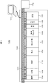
- FIG. 1 is a configuration diagram showing the overall configuration of the biological sample analyzer according to the first embodiment.
- a configuration is shown in which a biological sample (blood) collected from a patient is preprocessed and analyzed by an automatic analyzer.
- the biological sample analyzer 120 includes a pretreatment system 100, a control PC 111 that controls the entire pretreatment system 100, and an automatic analyzer 112 that analyzes components of the biological sample connected to the pretreatment system 100.
- the pretreatment system 100 includes a transfer line 101, a loading module 102, a centrifuge module 103, a specimen check module (detection device) 104, an opening module 105, a labeler 106 such as a barcode, a dispensing module 107, a closing module 108, a classification It consists of a plurality of modules having the module 109 and the storage module 110 as basic elements.
- a sample (a blood collection tube containing blood) is input, and in the centrifuge module 103, the input sample is centrifuged.
- the specimen check module 104 detects the type and volume of serum.
- the centrifuged specimen is opened, and in the dispensing module 107, the centrifuged specimen is subdivided for analysis by the automatic analyzer 112 or the like.
- the labeler 106 a barcode is attached to the subdivided container.
- the stopper module 108 closes the specimen plug, and the storage module 110 stores the stoppered specimen.
- the classification module 109 the dispensed sample containers are classified.
- Specimen analysis flow is as follows. First, patient blood (whole blood) is collected using a blood collection tube. The blood collection tube is input to the input module 102 of the pretreatment system 100. Blood collection and injection are performed manually by the user, and subsequent operations are automatic operations by the pretreatment system 100. In general, blood collection may be performed by a nurse, input is performed by a laboratory technician, and blood collection may be performed at a facility different from the facility where the biological sample analyzer is installed.
- the transfer line 101 takes charge of the transfer work.
- the input blood collection tube is conveyed to the centrifuge module 103 where it is centrifuged.
- the blood collection tube contains a separating agent in advance, and is separated into a clot layer having a relatively large specific gravity and a serum layer having a relatively small specific gravity and used for blood analysis by centrifugation.
- the centrifuged sample is carried to the sample check module 104, and the type and amount of serum are detected. Details of the detection method will be described later. Samples whose serum types are determined to be hemolysis, jaundice, and chyle are conveyed to the classification module 109 and classified as error samples.
- the specimen whose serum type is determined to be normal and whose serum volume has been detected is carried to the unplugging module 105.
- the stopper of the sample centrifuged by the opening module 105 is opened and carried to the dispensing module 107.
- the sub-container with the barcode attached by the labeler 106 is also carried to the dispensing module 107, and the sample is dispensed into the sub-container based on the serum volume information detected by the sample check module 104. .
- the sample for which the subdivision has been completed is transported to the closure module 108 where the specimen stopper is closed and stored in the storage module 110.
- the stored subdivided containers are transported to the automatic analyzer 112 for various component analysis.
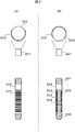
- FIG. 2 shows a relationship diagram between the camera and the direction of the label attached to the blood collection tube.
- the upper drawing of FIG. 2 is a top view, and the lower drawing is a side view.
- FIG. 2A shows a state in which the label 203 attached to the blood collection tube (container) 202 faces the camera 201 side.
- FIG. 2B shows a state in which the label 203 attached to the blood collection tube 202 faces away from the camera 201.
- the blood (sample) in the blood collection tube 202 is separated from the serum (serum region, first component) 204 in the upper part and the clot (clot region, second component) 205 in the lower part by the separating agent 206. .
- the blood collection tube 202 has a stopper 207.
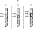
- Fig. 3 shows the relationship between the serum area and the position of the label attached to the surface of the blood collection tube.
- a label 203c may be attached to part of the serum region height direction. Since serum has a high transmittance, scattered light from an object behind the blood collection tube also enters the camera. Therefore, the serum region obtained by imaging with the camera is only the serum region 204L with the label 203a in the background in the case of FIG. 3A, and the background plate disposed at the rear of the blood collection tube in the case of FIG.
- the serum region 204L with the label 203c in the background and the serum region 204N with the background plate in the background are mixed. Become. At this time, even for the same serum, the color obtained by imaging with the camera differs between the serum area with the label as the background and the serum area with the background as the background.
- the color of the background plate is the same as the color of the label, the same color can be obtained in the serum region with the background of the label and the serum region with the background of the background plate for the same serum type.
- the background plate is black
- the illumination light is reflected by the background plate, so the shadow of the blood collection tube cap or label occurs in the serum area, and normal serum and hemolyzed / jaundice / chyle serum A sufficient color difference cannot be obtained. Therefore, it is necessary to use a black background plate that can prevent reflection of illumination light, and to detect the type and volume of serum even when the background plate has a different color from the label. Therefore, in the first embodiment and the second to sixth embodiments described later, imaging using a black background plate is possible with the following configuration, and serum is applied regardless of whether the label is attached or not. Detect the type and amount of liquid.
- the background plate is preferably one that can prevent reflection of illumination light. Specifically, for example, a background plate having a visible light region reflectance of 10% or less is used. Further, the color of the background plate is not limited to black. For example, a color that is complementary to the label may be used to clarify the label application / non-application area.
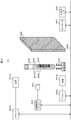
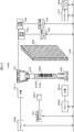
- FIG. 4 shows the configuration of the sample check module of the first embodiment.
- the sample check module (detection device) 104 includes light sources 401a and 401b, light source drivers (drivers) 402a and 402b, a camera (imaging unit) 201, an image processing engine (detection unit) 404, a blood collection tube holder (holding unit) 405, A background plate (background portion) 406, a controller 407, an input / output interface (input / output I / F) 408, and a data bus 409 are included.
- the light sources (irradiation elements) 401a and 401b which are irradiation units irradiate light from the upper front and lower front of the blood collection tube 202, respectively.
- LED light sources that are strong and have high directivity are used.
- the visible light having a wavelength range of approximately 400 nm to 700 nm is used.
- light source drivers 402a and 402b such as a power source are used.
- the intensity distribution of light hitting the blood collection tube can be made uniform as compared with the case where one light source is used.
- the serum color information can be obtained more accurately.
- light may be irradiated from the left and right of the front left side and the front right side of the blood collection tube 202. Since the shadow of the cap of the blood collection tube does not occur in the serum region by irradiation from the left and right of the front left side and the front right side, the serum color information can be accurately acquired.
- the camera 201 captures a two-dimensional image of the entire blood collection tube 202.
- the relationship between the direction of the label 203 attached to the camera 201 and the blood collection tube 202 is such that the sample in the blood collection tube 202 can be imaged from the gap between the label 203 and the label 203 as shown in FIG.
- the light emitted from the light sources 401 a and 401 b is transmitted through the blood collection tube 202, a part of the wavelength is absorbed by the serum 204 in the blood collection tube 202, and a part is transmitted through the serum 204.
- the transmitted light is transmitted through the blood collection tube 202 and scattered on the label 203 attached to the surface of the blood collection tube 202.
- the scattered light is again transmitted through the blood collection tube 202, the serum 204, and the blood collection tube 202 in this order and enters the camera 201.
- the image processing engine 404 performs image processing such as serum region extraction processing from the image captured by the camera 201 to recognize the position and color of the serum region.
- the input / output interface 408 is used as an interface, and is used when the detected serum type, amount display, data transmission, parameters used for the serum type, amount, etc. are input from the control PC 111.
- the controller 407 performs overall control of the sample check module 104.
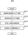
- FIG. 5 shows an operation flow of the sample check module according to the first embodiment.
- the labeled blood collection tube 202 is placed in the blood collection tube holder 405 (step S501).
- the entire blood collection tube 202 is imaged by the camera 201 (step S502).
- the captured image is an image as shown in FIGS. 3A to 3C due to the positional relationship between the serum region and the label in the blood collection axis direction.
- the image picked up by the camera 201 is subjected to image processing by the image processing engine 404 (step S503).
- Information on the serum type and the serum amount detected by the image processing is output (step S504).
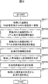
- Fig. 6 shows an example of the image processing flow.
- the acquired image is converted from the RGB color system to the HSV color system (step S601).
- the HSV color system is known to be similar to the method of human perception of color, and is suitable for automating the recognition of serum types, which has been performed manually.
- a labeled serum region 204L which is a serum region with the label as a background, is extracted (step S602).
- the unlabeled serum region 204N with the background plate 406 installed at the rear of the blood collection tube 202 is extracted (step S603). As shown in FIG.
- the HSV color system threshold for extracting the labeled serum region 204L with the label as the background and the HSV table for extracting the non-labeled serum region 204N with the background plate 406 installed at the rear of the blood collection tube 202 as the background.
- Color system threshold values are set in advance, and each of the labeled serum region 204L and the non-labeled serum region 204N is extracted by threshold processing.
- thresholds used for extracting the labeled serum region 204L and the unlabeled serum region 204N are set in advance. Further, it may be changed according to the type of the blood collection tube 202, the light amounts of the light sources 401a and 401b, the setting value of the camera 201, and the like. Depending on the type of the blood collection tube 202, the wall material is different and the light transmittance is different. Therefore, even in the case of similar serum, the color in the image captured by the camera 201 may be different. Therefore, the serum region 204 can be extracted more accurately by changing the region extraction threshold according to the type of the blood collection tube 202.
- serum color information is acquired (step S604). Since the label-attached serum region 204L and the non-label-attached serum region 204N have different colors, color information is extracted from either one of the regions. For example, the average value of the color of the labeled serum region 204L is acquired as the serum color. In general, since there are many blood collection tubes with a label attached to the back of the serum region, it is effective to acquire color information from the labeled serum region 204L in this way.
- the acquisition of color information is not limited to this, and the color information may be acquired from the label non-pasted area 204N. Further, depending on the positional relationship between the serum region 204 and the label 203, it may be selected from which region the color information is acquired. For example, in the case of the positional relationship shown in FIG. 3A, the color information may be acquired from the label attaching region 204L, and in the case of the positional relationship shown in FIG. 3B, the color information may be acquired from the non-labeled serum region 204N. In the case of the positional relationship shown in FIG. 3C, the color information of any region may be acquired, or the color information of the wider region may be acquired.
- color information is acquired using information on the labeled serum region 204L and the non-labeled serum region 204N.
- the serum type is determined from the acquired color information (step S605).
- a threshold is used to determine the serum type, and normal, hemolysis, jaundice, chyle, etc. are determined.
- the threshold is set in advance according to the serum region with the label 203 as the background.
- the threshold value set in advance is compared with the color information of the acquired serum, and the serum type is determined.
- a serum type determination threshold in accordance with the serum region with the background plate 406 behind the blood collection tube 202 as a background. As shown in FIG. 3B, it is possible to determine the serum type even in the case of only the non-labeled serum region 204N.
- the threshold value for determining the serum type may be changed according to the type of the blood collection tube 202, the light amounts of the light sources 401a and 401b, the setting value of the camera 201, and the like.
- the wall material is different and the light transmittance is different. Therefore, even in the case of similar serum, the color in the image captured by the camera 201 may be different. For this reason, it is possible to more accurately discriminate the serum type by changing the region extraction threshold according to the type of blood collection tube.
- the position of the serum boundary surface is acquired (step S606).
- both the extracted labeled serum region 204L and the unlabeled serum region 204N are used.
- an area (bonding area) obtained by combining both areas with and without labeling is calculated, and the boundary between the bonding area and the area above it (vacuum) and the bonding area and the area below it (separation)
- the serum boundary surface is obtained from the coordinate information of the boundary of the agent 206). From the acquired position of the boundary surface, the amount of serum is calculated using the diameter of the blood collection tube 202 as a parameter (step S607).
- Information on the calculated serum type and serum volume is controlled by the controller 407, and is output to the control PC 111 via the input / output interface 408 (step S504), and is used for excluding error specimens and determining insufficient liquid volume. .
- the serum type can be accurately determined by extracting the labeled serum region and the non-labeled serum region, respectively, and extracting the color information from the labeled serum region.
- the amount of serum can be obtained accurately by calculating the serum boundary surface from both the labeled serum region and the unlabeled serum region.
- Example 1 the relationship between the camera and the direction of the label affixed to the blood collection tube was set in a state where the sample in the blood collection tube could be imaged from the gap between the label as shown in FIG.
- the sample installed in the blood collection tube holder and carried to the sample check module is not always in the state of FIG. Therefore, in this embodiment, a method for acquiring the image in the state of FIG. 2B regardless of the state of the relationship between the camera and the direction of the label attached to the blood collection tube will be described.
- the biological sample analyzer of the second embodiment is basically the same as the biological sample analyzer 120 of the first embodiment except for the specimen check module.
- FIG. 7 shows the configuration of the sample check module of the second embodiment.
- the specimen check module (detection device) 104A includes light sources 401a and 401b, light source drivers 402a and 402b, a camera (imaging unit) 201, an image processing engine (detection unit) 404, a blood collection tube holder (holding unit) 405, a background plate ( (Background part) 406, controller 407, input / output interface 408, data bus 409, gripping mechanism 701, moving mechanism 702, vertical control driver 703, rotating mechanism 704, and rotation control driver 705.
- Light sources (irradiation elements) 401a and 401b which are irradiation units, irradiate light from the upper front and lower front of the blood collection tube 202, respectively, and the camera 201 captures a two-dimensional image of the entire blood collection tube 202.
- the label 203 is affixed to the surface of the blood collection tube 202 on the camera 201 as shown in FIG. 2A
- the light emitted from the light sources 401a and 401b is scattered on the label 203 affixed to the surface of the blood collection tube 202.
- the light enters the camera 201.
- the sample in the blood collection tube 202 can be imaged from the gap between the label 203 and the label 203 as shown in FIG.
- the light emitted from the light sources 401a and 401b passes through the blood collection tube 202 and a part of the wavelength. Is absorbed by the serum 204 in the blood collection tube 202, and part of the blood permeates the serum 204.
- the transmitted light is transmitted through the blood collection tube 202 and scattered on the label 203 attached to the surface of the blood collection tube 202.
- the scattered light is again transmitted through the blood collection tube 202, the serum 204, and the blood collection tube 202 in this order and enters the camera 201.
- the image processing engine 404 performs image processing such as serum region extraction processing from the image captured by the camera 201 to recognize the position of the label 203 and the position and color of the serum region 204.
- light may be irradiated from the left and right of the front left side and the front right side of the blood collection tube 202.
- the gripping mechanism 701 grips and lifts the specimen that has been installed in the blood collection tube holder 405 and carried to the specimen check module, and moves the whole specimen by the moving mechanism 702 until it falls within the imaging range of the camera 201.
- Vertical movement is controlled by a vertical control driver (vertical control) 703.
- a vertical control driver vertical control 703.
- the specimen lifted by the gripping mechanism 701 is rotated by the rotating mechanism 704, and the positional relationship between the label 203 attached to the surface of the blood collection tube 202 and the camera 201 is changed so that the camera 201 can image the blood collection tube 202 once.
- the gripping mechanism 701 and the rotation mechanism 704 constitute a rotation unit.
- the rotation is controlled by a rotation control driver 705.
- the input / output interface 408 is used as an interface, and is used to input parameters and the like used for displaying the detected serum type and amount, transmitting data, and the type and amount of serum.
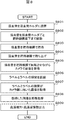
- FIG. 8 shows an operation flow of the sample check module of the second embodiment.
- the labeled blood collection tube 202 is placed in the blood collection tube holder 405 (step S801).
- the blood collection tube 202 is moved together with the blood collection tube holder 405 to just below the gripping mechanism 701 (step S802).
- the blood collection tube 202 is grasped by the grasping mechanism 701 (step S803), the entire blood collection tube 202 is lifted to a position where it can be imaged by the camera 201 (step S804), and a plurality of images are acquired by the camera 201 while being rotated (step S805).
- the image processing engine 404 recognizes the gap between the labels (step S806).
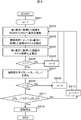
- FIG. 9 shows an example of a label-to-label gap recognition flow.
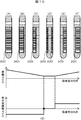
- FIG. 10 is an explanatory diagram showing changes in the area of the label accompanying changes in the direction of the blood collection tube according to the second embodiment. This flow is performed every time one image is acquired.
- the first acquired image is converted from the RGB color system to the HSV color system (step S902).
- the label 203 is extracted by the threshold processing (step S903).
- the threshold of the HSV color system for extracting labels is set in advance.
- the label area (S 1 ) is calculated from the extracted label region (step S904).
- the label area (S 2 ) is calculated from the second acquired image (step S904).
- step S907 the area change rate ( ⁇ S 2 ) of the label area in the second acquired image is calculated from the area of the label in the first acquired image (step S907).
- step S908 the area change rate ( ⁇ S n ) is calculated for the third and subsequent images (step S907).
- step S901 1 is substituted for n in order to perform processing for the first acquired image. Since the area change rate ( ⁇ S n ) can be calculated only after the second image is acquired, it is determined in step S905 whether it is the second or later.
- step S906 2 is substituted for n in order to perform processing for the second acquired image.
- step S909 3 is substituted for n in order to perform processing for the third acquired image.
- FIG. 10G shows the transition of the area change rate.
- the horizontal axis represents the angle of the blood collection tube 202 corresponding to FIGS. 10A to 10F, and the vertical axis represents the label area and the label area change rate.
- the label area in the state of FIG. 10 (A) is the largest, and the label area in the state of FIG. 10 (D) is the smallest.
- the label area decreases from FIG. 10A to FIG. 10D and increases from FIG. 10D to FIG. 10F.
- the sign of the area change rate ( ⁇ S n ) is reversed from negative to positive, it is determined that the gap between the labels is directed to the camera 201 (step S911), and the rotation is stopped (step S912).
- step S911 determines whether or not it is the third and subsequent images.
- step S909 3 is substituted for n in order to perform processing for the third acquired image.
- step S910 n is incremented to perform processing for the fourth and subsequent images.
- a label-attached serum region 204L with the label 203 as a background and a non-label-attached serum region 204N with a background plate 406 installed at the rear of the blood collection tube 202 are extracted from the acquired image (step S807) by threshold processing. From the extracted labeled serum region 204L and unlabeled serum region 204N, the serum type is determined and the serum amount is calculated in the same manner as in Example 1 (step S808), and the result is output (step S809).
- the direction of the label 203 attached to the camera 201 and the blood collection tube 202 is obtained by capturing an image while rotating the blood collection tube 202 and directing the gap between the label 203 and the label 203 toward the camera 201 side.
- an image of the state shown in FIG. 2B is acquired, and the background of the labeled plate serum region 204L with the label 203 as the background and the background plate 406 installed at the rear of the blood collection tube 202 is obtained.
- An unlabeled serum region 204N can be extracted.
- the rotation is stopped when it is determined that the gap between the label 203 and the label 203 faces the camera 201 side, but the present invention is not limited to this.
- a plurality of images may be captured while rotating the blood collection tube 202 360 degrees, and an image facing the camera 201 may be selected from the captured images. Since it is not necessary to stop and control the rotation in real time, it is suitable when the control takes time.
- the present invention is not limited to this.
- an image that maximizes the area of the serum region may be extracted, and it may be determined that the gap between the labels 203 faces the camera 201 side.
- Example 2 a plurality of images were acquired with the camera 201 while rotating, and the image in the state of FIG. 2B was acquired.
- a method for acquiring an image in a state equivalent to that in FIG. 2B from one image by using a line camera will be described.
- the biological sample analyzer of the third embodiment is basically the same as the biological sample analyzer 120 of the first embodiment except for the specimen check module.
- FIG. 20 shows the configuration of the sample check module of the third embodiment.
- a line camera 201L is used instead of the camera (area camera) 201 with the same configuration as that of the second embodiment.
- light may be emitted from the left and right front left and front right of the blood collection tube 202.
- FIG. 11 shows an operation flow of the sample check module according to the third embodiment.
- the blood collection tube 202 to which the label 203 is attached is placed on the blood collection tube holder 405 (step S1101).
- the blood collection tube 202 is moved together with the blood collection tube holder 405 to directly below the gripping mechanism 701 (step S1102).
- the blood collection tube 202 is grasped by the grasping mechanism 701 (step S1103), the whole blood collection tube 202 is lifted to a position where it can be imaged by the camera 201L (step S1104), and the image for one round of the blood collection tube 202 is rotated by the line camera 201L while rotating. Is obtained (step S1105).
- the image processing engine 404 recognizes the gap between the label 203 and the label 203 (step S1106).
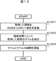
- Fig. 12 shows an example of a flow for recognizing labels between labels.
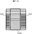
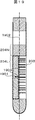
- FIG. 13 shows an example of an image captured by the line camera.
- the acquired image is converted from the RGB color system to the HSV color system (step S1201).
- the threshold of the HSV color system for extracting the label is set in advance, and the label 203 is extracted by threshold processing (step S1202).
- the gap 1302 between the label 203 and the label 203 is recognized (step S1203).
- the serum color and amount are detected, and the result is output (step S1107).
- processing can be performed with one image, and processing for calculating the area of the label can be eliminated. Time can be shortened.
- the serum-separation agent interface and the clot-separation agent interface may be inclined in the depth direction when viewed from the camera side.
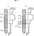
- FIG. 14 shows an example of the color change rate in the direction of the blood collection tube axis.
- the color change rate in the direction of the blood collection tube axis is as shown in FIG. 14A, whereas when the interface has an inclination in the depth direction when viewed from the camera side, As shown in FIG. 14B, the direction color change rate is smaller than that in the case where the interface has no inclination, and the position of the clot-separating agent interface may be erroneously recognized.
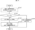
- FIG. 15 shows a detection flow of the interface between the serum and the separating agent using the color change rate.
- an image is acquired by the camera 201 while the blood collection tube 202 is rotated by the gripping mechanism 701.
- the image processing engine 404 recognizes the gap between the label 203 and the label 203, and extracts a label-attached serum region 204L with the label as a background and a non-label-attached serum region 204N with a background plate 406 installed at the rear of the blood collection tube 202 as a background. To do.
- the serum liquid level and the interface between the serum and the separating agent are detected from the color information of the labeled serum region 204L and the non-labeled serum region 204N. As shown in FIG.
- the color change rate ( ⁇ ca) is calculated (step S1501).
- the color change rate ( ⁇ ca) and the threshold value ( ⁇ ct1) are compared (step S1502). If the color change rate ( ⁇ ca) is greater than the threshold value ( ⁇ ct1), it is determined that there is no inclination of the serum-separating agent interface. (Step S1503). When the color change rate ( ⁇ ca) is smaller than the threshold value ( ⁇ ct1), as shown in FIG.
- the color change rate ( ⁇ cs) of the peripheral 1404 is calculated in the same manner as shown in FIG. 14B.
- the change rate ( ⁇ cs) of the color around ⁇ a pixels from the interface axis is calculated (step S1504), and the position where the color change rate ( ⁇ cs) is smaller than the threshold value ( ⁇ ct2) is determined as the serum-separation agent interface. (Step S1505).
- the position of the interface is recognized by using the color change rate in the blood collection axis direction. Can do.
- This embodiment can also be applied to the sample check module of the biological sample analyzer of the third embodiment.
- the size of the label-to-label gap width varies depending on the relationship between the label size and the blood collection tube diameter. Depending on the size of the gap width, the size of the label width attached to the camera side changes. Depending on the size of the label affixed to the camera side, the light from the light source passes through the blood collection tube and serum and scatters on the label, and the amount of light that retransmits the serum and blood collection tube differs, and the label generated in the serum region Therefore, even if the serum type is the same, the color obtained by imaging with the camera is different.
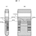
- FIG. 16 and FIG. 17 show the color determination flow and explanatory diagram of the serum region using the size of the gap width between the labels as a parameter.
- FIG. 17A is an image captured by an area camera
- FIG. 17B is an image captured by a line camera.
- the gap widths (Wm) 1701a and 1701b between the label 203 and the label 203 are measured from the color information of the labeled serum region 204L (step S1601).
- the gap widths (Wm) 1701a and 1701b are compared with the threshold value (Wt) (step S1602). If the gap widths (Wm) 1701a and 1701b are smaller than the threshold value (Wt), the correction coefficient ( ⁇ ) applied to the serum color is calculated.
- the gap width (Wm) is calculated from the sizes of 1701a and 1701b (step S1603).
- the correction coefficient ( ⁇ ) applied to the serum color is set to 1 (step S1604).
- the corrected serum color is calculated by multiplying the serum color by the correction coefficient ( ⁇ ) (step S1605), and the type of serum is determined from the corrected serum color (step S1606).
- the correction calculation formula described in the present embodiment is an example, and correction may be performed according to another calculation formula.
- the type of serum can be determined regardless of the size of the gap width between the labels.
- the blood collection tube radial direction in the gap width between the labels has been described, but the serum type can also be determined based on the same concept in the blood collection tube axial direction.
- the size of the label width affixed to the camera side changes depending on the direction of the blood collection tube.
- the light from the light source passes through the blood collection tube and serum and scatters on the label, and the amount of light that retransmits the serum and blood collection tube differs, and the label generated in the serum region Therefore, even if the serum type is the same, the color obtained by imaging with the camera is different. Therefore, in the present embodiment, a method for determining the color of the serum region using the direction of the blood collection tube as a parameter will be described.
- a present Example demonstrates based on the sample check module of the analyzer of the biological sample of Example 2.
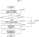
- FIG. 18 and FIG. 19 show the color determination flow and explanatory diagram of the serum region using the direction of the blood collection tube as a parameter.
- an image is acquired by the camera 201 while the blood collection tube 202 is rotated by the gripping mechanism 701.
- a gap between the label 203 and the label 203 is recognized by the image processing engine 404, and a label-attached serum region 204L with the label 203 as a background and a non-label-attached serum region 204N with a background plate 406 installed at the rear of the blood collection tube 202 as a background Extract.
- FIG. 18 and FIG. 19 show the color determination flow and explanatory diagram of the serum region using the direction of the blood collection tube as a parameter.
- the distance (Dm) 1903 between the center of gravity 1901 of the gap region between the label 203 and the label 203 and the blood collection tube axis 1902 is measured from the color information of the labeled serum region 204L (step S1801).
- the distance (Dm) 1903 is compared with the threshold value (Dt) (step S1802).
- the correction coefficient ( ⁇ ) applied to the serum color is calculated from the distance (Dm) 1903. Calculate (step S1803).
- the correction coefficient ( ⁇ ) is set to 1 (step S1804).
- the corrected serum color is calculated by multiplying the serum color by the correction coefficient ( ⁇ ) (step S1805), and the type of serum is determined from the corrected serum color (step S1806).
- the correction calculation formula described in the present embodiment is an example, and correction may be performed according to another calculation formula.
- a black color that prevents reflection of illumination light as the color of the background plate
- an effect of suppressing the shadow of the blood collection cap or label in the serum region can be obtained.
- a specimen such as jaundice (dark yellow) with low lightness
- a sufficient color difference between the unlabeled serum area and the background plate cannot be obtained, and the serum area may be erroneously extracted. Therefore, in this embodiment, a method using a color with a high brightness, for example, a white background plate, will be described in order to be applicable to imaging of a specimen with a low brightness. Since the white background plate has a high reflectance, it is necessary to perform processing for reducing regular reflection light on the background plate.
- the present embodiment can be applied to the sample check module of the biological sample analyzer of the first to third embodiments. Further, the present invention can be applied to the sample check module using the fourth to sixth embodiments.
- DESCRIPTION OF SYMBOLS 100 ... Pretreatment system 101 ... Conveyance line 102 ... Input module 103 ... Centrifugation module 104, 104A, 104B ... Sample check module 105 ... Opening module 106 ... Labeler 107 ... Dispensing module 108 ... Closing module 109 ... Classification module 110 ... Storage module 111 ... PC for control 112 ... Automatic analyzer 120 ... Biological sample analyzer 201 ... Camera (area camera) 201L ... line camera 202 ... blood collection tube 203, 203a, 203b, 203c ... label 204 ...
Landscapes
- Health & Medical Sciences (AREA)
- Life Sciences & Earth Sciences (AREA)
- Chemical & Material Sciences (AREA)
- Physics & Mathematics (AREA)
- Engineering & Computer Science (AREA)
- Biomedical Technology (AREA)
- Pathology (AREA)
- Hematology (AREA)
- Immunology (AREA)
- General Physics & Mathematics (AREA)
- General Health & Medical Sciences (AREA)
- Biochemistry (AREA)
- Analytical Chemistry (AREA)
- Dispersion Chemistry (AREA)
- Medicinal Chemistry (AREA)
- Food Science & Technology (AREA)
- Ecology (AREA)
- Urology & Nephrology (AREA)
- Molecular Biology (AREA)
- Biophysics (AREA)
- Investigating Or Analysing Biological Materials (AREA)
- Automatic Analysis And Handling Materials Therefor (AREA)
- Investigating Or Analysing Materials By Optical Means (AREA)
Priority Applications (3)
| Application Number | Priority Date | Filing Date | Title |
|---|---|---|---|
| US14/897,795 US9880082B2 (en) | 2013-07-04 | 2014-07-02 | Detection device that calculates a center of gravity of a container gap region |
| EP14820069.4A EP3018482B1 (en) | 2013-07-04 | 2014-07-02 | Detection device and biological-sample analysis device |
| CN201480033783.1A CN105324671B (zh) | 2013-07-04 | 2014-07-02 | 检测装置以及生物体试样分析装置 |
Applications Claiming Priority (2)
| Application Number | Priority Date | Filing Date | Title |
|---|---|---|---|
| JP2013140729A JP6143584B2 (ja) | 2013-07-04 | 2013-07-04 | 検出装置および生体試料分析装置 |
| JP2013-140729 | 2013-07-04 |
Publications (1)
| Publication Number | Publication Date |
|---|---|
| WO2015002218A1 true WO2015002218A1 (ja) | 2015-01-08 |
Family
ID=52143790
Family Applications (1)
| Application Number | Title | Priority Date | Filing Date |
|---|---|---|---|
| PCT/JP2014/067621 Ceased WO2015002218A1 (ja) | 2013-07-04 | 2014-07-02 | 検出装置および生体試料分析装置 |
Country Status (5)
| Country | Link |
|---|---|
| US (1) | US9880082B2 (enExample) |
| EP (1) | EP3018482B1 (enExample) |
| JP (1) | JP6143584B2 (enExample) |
| CN (1) | CN105324671B (enExample) |
| WO (1) | WO2015002218A1 (enExample) |
Cited By (9)
| Publication number | Priority date | Publication date | Assignee | Title |
|---|---|---|---|---|
| US10209267B1 (en) | 2015-12-31 | 2019-02-19 | Cerner Innovation, Inc. | Sample extraction and rotation device for automated blood sample processing systems |
| US10267813B1 (en) | 2015-12-31 | 2019-04-23 | Cerner Innovation, Inc. | Monitoring specimen integrity in automated blood sample processing system |
| JP2019511700A (ja) * | 2016-01-28 | 2019-04-25 | シーメンス・ヘルスケア・ダイアグノスティックス・インコーポレーテッドSiemens Healthcare Diagnostics Inc. | 試料中のインターフェレントを検出するための方法と装置 |
| US10311569B1 (en) | 2015-12-31 | 2019-06-04 | Cerner Innovation, Inc. | Identifying liquid blood components from sensed data to monitor specimen integrity |
| US10527635B1 (en) * | 2015-12-31 | 2020-01-07 | Cerner Innovation, Inc. | Specimen integrity monitoring device for automated blood sample processing systems |
| US11009499B2 (en) | 2017-06-09 | 2021-05-18 | Roche Diagnostics Operations, Inc. | Method and apparatus for determining properties of a laboratory sample contained in a laboratory sample container by tomographic reconstruction |
| US11085913B2 (en) | 2016-12-09 | 2021-08-10 | Hitachi High-Tech Corporation | Biological sample analyzer |
| WO2024162076A1 (ja) * | 2023-02-01 | 2024-08-08 | 株式会社日立ハイテク | 採血装置 |
| WO2025062968A1 (ja) * | 2023-09-22 | 2025-03-27 | 株式会社日立ハイテク | 試料状態判定装置、試料状態判定方法、および試料分析システム |
Families Citing this family (33)
| Publication number | Priority date | Publication date | Assignee | Title |
|---|---|---|---|---|
| USD978375S1 (en) | 2013-03-13 | 2023-02-14 | Abbott Laboratories | Reagent container |
| CN107966576B (zh) | 2013-03-15 | 2021-08-03 | 雅培制药有限公司 | 具有后面可进入轨道系统的自动化诊断分析仪及相关方法 |
| US11009467B2 (en) | 2015-02-17 | 2021-05-18 | Siemens Healthcare Diagnostics Inc. | Model-based methods and apparatus for classifying an interferent in specimens |
| JP6422824B2 (ja) * | 2015-05-29 | 2018-11-14 | 株式会社日立ハイテクノロジーズ | 検体前処理方法及び検体前処理装置 |
| EP3408652B1 (en) * | 2016-01-28 | 2020-12-16 | Siemens Healthcare Diagnostics Inc. | Methods and apparatus for classifying an artifact in a specimen |
| EP3408653B1 (en) * | 2016-01-28 | 2024-01-17 | Siemens Healthcare Diagnostics Inc. | Methods and apparatus adapted to quantify a specimen from multiple lateral views |
| JP6592401B2 (ja) * | 2016-05-26 | 2019-10-16 | 株式会社日立ハイテクノロジーズ | 試料液面位置計測装置及び試料液面位置計測方法 |
| US10648905B2 (en) * | 2016-08-31 | 2020-05-12 | Abbott Laboratories | Systems, apparatus, and related methods for evaluating biological sample integrity |
| US11022620B2 (en) | 2016-11-14 | 2021-06-01 | Siemens Healthcare Diagnostics Inc. | Methods, apparatus, and quality check modules for detecting hemolysis, icterus, lipemia, or normality of a specimen |
| WO2018188023A1 (en) * | 2017-04-13 | 2018-10-18 | Siemens Healthcare Diagnostics Inc. | Methods and apparatus for determining label count during specimen characterization |
| EP3610270B1 (en) * | 2017-04-13 | 2024-05-29 | Siemens Healthcare Diagnostics Inc. | Methods and apparatus for label compensation during specimen characterization |
| CN107170014A (zh) * | 2017-04-27 | 2017-09-15 | 张亚希 | 液体颜色变化的观测方法、装置及系统 |
| EP3737930B1 (en) * | 2018-01-10 | 2025-11-05 | Siemens Healthcare Diagnostics, Inc. | Methods and apparatus for bio-fluid specimen characterization using neural network having reduced training |
| CN108414777A (zh) * | 2018-02-08 | 2018-08-17 | 前海瑞智捷自动化科技(深圳)有限公司 | 一种血样检验流水线及方法、出样设备 |
| CN108562584A (zh) * | 2018-06-01 | 2018-09-21 | 安图实验仪器(郑州)有限公司 | 血清质量判别方法 |
| JP7089072B2 (ja) * | 2018-06-15 | 2022-06-21 | シーメンス・ヘルスケア・ダイアグノスティックス・インコーポレイテッド | 進歩したセマンティックセグメンテーションおよび敵対的訓練による、きめ細かなhil指標決定のための方法および装置 |
| US11906346B2 (en) * | 2018-08-23 | 2024-02-20 | Hitachi High-Tech Corporation | Liquid level detection device that irradiates a container at multiple angles |
| US11386551B2 (en) * | 2018-11-08 | 2022-07-12 | Perkinelmer Health Sciences, Inc. | Method and apparatus for buffy coat imaging |
| JP7071301B2 (ja) * | 2019-01-25 | 2022-05-18 | 株式会社日立ハイテク | 生体試料検出装置 |
| IT201900006738A1 (it) * | 2019-05-10 | 2020-11-10 | Inpeco Holding Ltd | Dispositivo e procedimento per screening di un campione biologico |
| JP7273631B2 (ja) * | 2019-06-26 | 2023-05-15 | 株式会社日立製作所 | 検体性状識別装置、検体性状識別方法及び検体搬送システム |
| JP7321514B2 (ja) | 2019-08-29 | 2023-08-07 | あおい精機株式会社 | 検体処理装置及び検体処理方法 |
| CN114599981A (zh) | 2019-10-31 | 2022-06-07 | 美国西门子医学诊断股份有限公司 | 用于在自动化诊断分析系统中试样的hiln确定中使用的训练图像的散列和检索的方法和设备 |
| CN114586033B (zh) | 2019-10-31 | 2025-09-16 | 美国西门子医学诊断股份有限公司 | 用于在自动化诊断分析系统中对患者进行表征期间保护患者信息的方法和装置 |
| JP7465963B2 (ja) * | 2019-10-31 | 2024-04-11 | シーメンス・ヘルスケア・ダイアグノスティックス・インコーポレイテッド | 試料および/または試料容器の特性評価のための背景照明の較正を提供する方法および装置 |
| JP7436270B2 (ja) * | 2020-04-09 | 2024-02-21 | 株式会社日立ハイテク | 生体検体解析装置 |
| CN114092483B (zh) * | 2020-07-31 | 2025-08-08 | 深圳市帝迈生物技术有限公司 | 试管检测方法、装置、血液分析仪及可读存储介质 |
| CN113514123A (zh) * | 2021-04-25 | 2021-10-19 | 安图实验仪器(郑州)有限公司 | 一种采血管血清液位检测方法和装置 |
| CN114062084B (zh) * | 2021-11-19 | 2022-09-06 | 深圳瑞智捷医疗科技有限公司 | 血液样本前处理一体机 |
| US20250067762A1 (en) * | 2021-12-29 | 2025-02-27 | Autobio Labtec Instruments Co., Ltd. | Online uncapping system |
| CN114339046B (zh) * | 2021-12-30 | 2023-10-03 | 中元汇吉生物技术股份有限公司 | 基于自动旋转试管的图像采集方法、装置、设备及介质 |
| CN116385457A (zh) * | 2023-02-24 | 2023-07-04 | 迈克医疗电子有限公司 | 血清区域识别方法、装置、介质和系统 |
| CN116609330A (zh) * | 2023-05-31 | 2023-08-18 | 郑州安图生物工程股份有限公司 | 血清、血浆中干扰物的识别方法及装置 |
Citations (11)
| Publication number | Priority date | Publication date | Assignee | Title |
|---|---|---|---|---|
| JPH0798239A (ja) * | 1993-08-31 | 1995-04-11 | Sugai Kiki Kk | 透明容器内試料の分量測定方法およびその装置 |
| JPH09133687A (ja) * | 1995-11-13 | 1997-05-20 | Meiji Denki Kogyo Kk | 採血試験管における血清量測定装置 |
| JPH1151746A (ja) * | 1997-07-31 | 1999-02-26 | Sumitomo Chem Co Ltd | 液面・界面位置検出装置および分液処理装置 |
| JP2001245874A (ja) * | 2000-03-03 | 2001-09-11 | Sefa Technology Kk | 赤血球沈降速度測定用採血管、採血管ホルダ、採血管運搬用プロテクタ、赤血球沈降速度測定方法およびその測定装置 |
| JP2004037322A (ja) * | 2002-07-04 | 2004-02-05 | Aloka Co Ltd | 検体分析装置 |
| JP2005140615A (ja) * | 2003-11-06 | 2005-06-02 | Esutekku:Kk | 血清の境界面検出手段 |
| US20060014295A1 (en) * | 2002-01-19 | 2006-01-19 | Michael Ziegler | Arrangement and method for the analysis of body fluids |
| JP2006200949A (ja) * | 2005-01-18 | 2006-08-03 | Teruaki Ito | 試験管の検知方法及び検知装置 |
| JP2010038659A (ja) | 2008-08-01 | 2010-02-18 | Sysmex Corp | 試料分析システム及び試料分析装置 |
| JP2012159318A (ja) * | 2011-01-31 | 2012-08-23 | Hitachi High-Technologies Corp | 分析装置 |
| JP2013242246A (ja) * | 2012-05-22 | 2013-12-05 | Hitachi High-Technologies Corp | 生体試料の分析装置および生体試料の分析方法 |
Family Cites Families (14)
| Publication number | Priority date | Publication date | Assignee | Title |
|---|---|---|---|---|
| US5443164A (en) * | 1993-08-10 | 1995-08-22 | Simco/Ramic Corporation | Plastic container sorting system and method |
| EP0882500A1 (en) | 1996-10-30 | 1998-12-09 | Sumitomo Chemical Company Limited | Synthesis experiment automating system, liquid separating treating apparatus and reaction vessel |
| JP2000088844A (ja) * | 1998-09-15 | 2000-03-31 | Yamahisa Kasei:Kk | 比重分離した血液の検査装置 |
| JP2001050792A (ja) * | 1999-08-10 | 2001-02-23 | Sefa Technology Kk | 透明容器内試料の分量測定方法およびその装置 |
| JP3602063B2 (ja) * | 2001-03-23 | 2004-12-15 | 株式会社日立製作所 | 検出対象の寸法を自動的に検出する装置及びそれを用いた自動分析装置 |
| JP2005017219A (ja) * | 2003-06-27 | 2005-01-20 | Shibazaki Seisakusho:Kk | 血清の境界面検出手段 |
| JP2005345145A (ja) * | 2004-05-31 | 2005-12-15 | Aloka Co Ltd | 界面検出装置、体積計測装置、及び界面検出方法 |
| JP2005345373A (ja) * | 2004-06-04 | 2005-12-15 | Aloka Co Ltd | 界面検出方法および界面検出装置 |
| WO2011019576A1 (en) * | 2009-08-13 | 2011-02-17 | Siemens Healthcare Diagnostics Inc. | Methods and apparatus for ascertaining interferents and physical dimensions in liquid samples and containers to be analyzed by a clinical analyzer |
| JP5330313B2 (ja) * | 2010-05-24 | 2013-10-30 | 株式会社日立ハイテクノロジーズ | 生体試料の分析装置 |
| US8973293B2 (en) * | 2010-11-19 | 2015-03-10 | Becton, Dickinson And Company | Specimen container label for automated clinical laboratory processing systems |
| EP2455761B1 (de) * | 2010-11-23 | 2018-08-08 | Hach Lange GmbH | Verfahren zum Auffinden einer optischen Kennzeichnung auf einer Laboranalyse-Küvette |
| JP5474903B2 (ja) * | 2011-09-28 | 2014-04-16 | あおい精機株式会社 | 検査前処理装置、検査前処理方法、及び検体処理装置 |
| WO2014031576A1 (en) * | 2012-08-20 | 2014-02-27 | Siemens Healthcare Diagnostics Inc. | Methods and apparatus for ascertaining specimen and/or sample container characteristics while in transit |
-
2013
- 2013-07-04 JP JP2013140729A patent/JP6143584B2/ja active Active
-
2014
- 2014-07-02 EP EP14820069.4A patent/EP3018482B1/en active Active
- 2014-07-02 CN CN201480033783.1A patent/CN105324671B/zh active Active
- 2014-07-02 US US14/897,795 patent/US9880082B2/en active Active
- 2014-07-02 WO PCT/JP2014/067621 patent/WO2015002218A1/ja not_active Ceased
Patent Citations (11)
| Publication number | Priority date | Publication date | Assignee | Title |
|---|---|---|---|---|
| JPH0798239A (ja) * | 1993-08-31 | 1995-04-11 | Sugai Kiki Kk | 透明容器内試料の分量測定方法およびその装置 |
| JPH09133687A (ja) * | 1995-11-13 | 1997-05-20 | Meiji Denki Kogyo Kk | 採血試験管における血清量測定装置 |
| JPH1151746A (ja) * | 1997-07-31 | 1999-02-26 | Sumitomo Chem Co Ltd | 液面・界面位置検出装置および分液処理装置 |
| JP2001245874A (ja) * | 2000-03-03 | 2001-09-11 | Sefa Technology Kk | 赤血球沈降速度測定用採血管、採血管ホルダ、採血管運搬用プロテクタ、赤血球沈降速度測定方法およびその測定装置 |
| US20060014295A1 (en) * | 2002-01-19 | 2006-01-19 | Michael Ziegler | Arrangement and method for the analysis of body fluids |
| JP2004037322A (ja) * | 2002-07-04 | 2004-02-05 | Aloka Co Ltd | 検体分析装置 |
| JP2005140615A (ja) * | 2003-11-06 | 2005-06-02 | Esutekku:Kk | 血清の境界面検出手段 |
| JP2006200949A (ja) * | 2005-01-18 | 2006-08-03 | Teruaki Ito | 試験管の検知方法及び検知装置 |
| JP2010038659A (ja) | 2008-08-01 | 2010-02-18 | Sysmex Corp | 試料分析システム及び試料分析装置 |
| JP2012159318A (ja) * | 2011-01-31 | 2012-08-23 | Hitachi High-Technologies Corp | 分析装置 |
| JP2013242246A (ja) * | 2012-05-22 | 2013-12-05 | Hitachi High-Technologies Corp | 生体試料の分析装置および生体試料の分析方法 |
Non-Patent Citations (1)
| Title |
|---|
| See also references of EP3018482A4 |
Cited By (12)
| Publication number | Priority date | Publication date | Assignee | Title |
|---|---|---|---|---|
| US10209267B1 (en) | 2015-12-31 | 2019-02-19 | Cerner Innovation, Inc. | Sample extraction and rotation device for automated blood sample processing systems |
| US10267813B1 (en) | 2015-12-31 | 2019-04-23 | Cerner Innovation, Inc. | Monitoring specimen integrity in automated blood sample processing system |
| US10311569B1 (en) | 2015-12-31 | 2019-06-04 | Cerner Innovation, Inc. | Identifying liquid blood components from sensed data to monitor specimen integrity |
| US10527635B1 (en) * | 2015-12-31 | 2020-01-07 | Cerner Innovation, Inc. | Specimen integrity monitoring device for automated blood sample processing systems |
| US10545163B1 (en) | 2015-12-31 | 2020-01-28 | Cerner Innovation, Inc. | Sample extraction and rotation device for automated blood sample processing systems |
| US11125763B1 (en) | 2015-12-31 | 2021-09-21 | Cerner Innovation, Inc. | Specimen integrity monitoring device for automated blood sample processing systems |
| US11125764B1 (en) | 2015-12-31 | 2021-09-21 | Cerner Innovation, Inc. | Specimen integrity monitoring device for automated blood sample processing systems |
| JP2019511700A (ja) * | 2016-01-28 | 2019-04-25 | シーメンス・ヘルスケア・ダイアグノスティックス・インコーポレーテッドSiemens Healthcare Diagnostics Inc. | 試料中のインターフェレントを検出するための方法と装置 |
| US11085913B2 (en) | 2016-12-09 | 2021-08-10 | Hitachi High-Tech Corporation | Biological sample analyzer |
| US11009499B2 (en) | 2017-06-09 | 2021-05-18 | Roche Diagnostics Operations, Inc. | Method and apparatus for determining properties of a laboratory sample contained in a laboratory sample container by tomographic reconstruction |
| WO2024162076A1 (ja) * | 2023-02-01 | 2024-08-08 | 株式会社日立ハイテク | 採血装置 |
| WO2025062968A1 (ja) * | 2023-09-22 | 2025-03-27 | 株式会社日立ハイテク | 試料状態判定装置、試料状態判定方法、および試料分析システム |
Also Published As
| Publication number | Publication date |
|---|---|
| EP3018482A4 (en) | 2017-03-01 |
| US9880082B2 (en) | 2018-01-30 |
| JP2015014506A (ja) | 2015-01-22 |
| CN105324671B (zh) | 2017-07-07 |
| EP3018482B1 (en) | 2020-05-13 |
| CN105324671A (zh) | 2016-02-10 |
| EP3018482A1 (en) | 2016-05-11 |
| JP6143584B2 (ja) | 2017-06-07 |
| US20160109350A1 (en) | 2016-04-21 |
Similar Documents
| Publication | Publication Date | Title |
|---|---|---|
| JP6143584B2 (ja) | 検出装置および生体試料分析装置 | |
| JP5330313B2 (ja) | 生体試料の分析装置 | |
| JP5330317B2 (ja) | 生体試料の分析方法および分析装置 | |
| JP6453564B2 (ja) | 検出装置 | |
| US11085913B2 (en) | Biological sample analyzer | |
| EP3488249B1 (en) | Systems, methods and apparatus for identifying a specimen container cap | |
| CN109073448B (zh) | 试样液面位置测量装置和试样液面位置测量方法 | |
| JP5414707B2 (ja) | 分析装置 | |
| CN107076732B (zh) | 用于管检查和液位检测的方法及系统 | |
| JP6510420B2 (ja) | 検体検査自動化システムおよび生体試料チェックモジュールならびに生体試料のチェック方法 | |
| JP6470691B2 (ja) | 検体検査自動化システムおよび容量チェックモジュールならびに生体試料のチェック方法 | |
| JP6282060B2 (ja) | 検体検査自動化システム | |
| JP5930865B2 (ja) | 検出装置および生体試料分析装置 | |
| JP6422824B2 (ja) | 検体前処理方法及び検体前処理装置 | |
| JP2013242246A (ja) | 生体試料の分析装置および生体試料の分析方法 | |
| JP6516727B2 (ja) | 検体検査自動化システムおよびチェックモジュールならびに試料のチェック方法 | |
| JP7171460B2 (ja) | 検体検査装置、及びシステム |
Legal Events
| Date | Code | Title | Description |
|---|---|---|---|
| WWE | Wipo information: entry into national phase |
Ref document number: 201480033783.1 Country of ref document: CN |
|
| 121 | Ep: the epo has been informed by wipo that ep was designated in this application |
Ref document number: 14820069 Country of ref document: EP Kind code of ref document: A1 |
|
| WWE | Wipo information: entry into national phase |
Ref document number: 14897795 Country of ref document: US |
|
| WWE | Wipo information: entry into national phase |
Ref document number: 2014820069 Country of ref document: EP |
|
| NENP | Non-entry into the national phase |
Ref country code: DE |