WO2015002218A1 - Detection device and biological-sample analysis device - Google Patents
Detection device and biological-sample analysis device Download PDFInfo
- Publication number
- WO2015002218A1 WO2015002218A1 PCT/JP2014/067621 JP2014067621W WO2015002218A1 WO 2015002218 A1 WO2015002218 A1 WO 2015002218A1 JP 2014067621 W JP2014067621 W JP 2014067621W WO 2015002218 A1 WO2015002218 A1 WO 2015002218A1
- Authority
- WO
- WIPO (PCT)
- Prior art keywords
- serum
- label
- region
- background
- container
- Prior art date
Links
- 238000001514 detection method Methods 0.000 title claims abstract description 55
- 239000012472 biological sample Substances 0.000 title claims abstract description 25
- 238000004458 analytical method Methods 0.000 title description 7
- 239000000523 sample Substances 0.000 claims abstract description 62
- 238000003384 imaging method Methods 0.000 claims abstract description 29
- 210000002966 serum Anatomy 0.000 claims description 202
- 230000008859 change Effects 0.000 claims description 28
- 230000005484 gravity Effects 0.000 claims description 7
- 230000001678 irradiating effect Effects 0.000 claims description 2
- 239000003086 colorant Substances 0.000 abstract description 3
- 210000004369 blood Anatomy 0.000 description 151
- 239000008280 blood Substances 0.000 description 151
- 238000012545 processing Methods 0.000 description 32
- 230000007246 mechanism Effects 0.000 description 24
- 239000003795 chemical substances by application Substances 0.000 description 21
- 238000000034 method Methods 0.000 description 17
- 238000010586 diagram Methods 0.000 description 11
- 238000012937 correction Methods 0.000 description 10
- 206010023126 Jaundice Diseases 0.000 description 6
- 238000005286 illumination Methods 0.000 description 6
- 210000001268 chyle Anatomy 0.000 description 5
- 238000000605 extraction Methods 0.000 description 5
- 239000007788 liquid Substances 0.000 description 5
- 239000004417 polycarbonate Substances 0.000 description 5
- 238000000926 separation method Methods 0.000 description 5
- 206010018910 Haemolysis Diseases 0.000 description 4
- 230000008588 hemolysis Effects 0.000 description 4
- 238000002834 transmittance Methods 0.000 description 4
- 238000005119 centrifugation Methods 0.000 description 3
- 239000000284 extract Substances 0.000 description 3
- 239000000463 material Substances 0.000 description 3
- 238000012546 transfer Methods 0.000 description 3
- 230000002093 peripheral effect Effects 0.000 description 2
- 230000008569 process Effects 0.000 description 2
- 208000007536 Thrombosis Diseases 0.000 description 1
- 238000002835 absorbance Methods 0.000 description 1
- 230000005540 biological transmission Effects 0.000 description 1
- 238000004159 blood analysis Methods 0.000 description 1
- 230000000295 complement effect Effects 0.000 description 1
- 230000007423 decrease Effects 0.000 description 1
- 230000000694 effects Effects 0.000 description 1
- 230000006870 function Effects 0.000 description 1
- 238000002347 injection Methods 0.000 description 1
- 239000007924 injection Substances 0.000 description 1
- 238000002372 labelling Methods 0.000 description 1
- 238000005259 measurement Methods 0.000 description 1
- 238000002156 mixing Methods 0.000 description 1
- 239000000203 mixture Substances 0.000 description 1
- 230000003287 optical effect Effects 0.000 description 1
- 230000008447 perception Effects 0.000 description 1
- 239000012466 permeate Substances 0.000 description 1
- 229920000515 polycarbonate Polymers 0.000 description 1
- 238000007781 pre-processing Methods 0.000 description 1
- 230000003252 repetitive effect Effects 0.000 description 1
- 230000004044 response Effects 0.000 description 1
- 238000012360 testing method Methods 0.000 description 1
- 230000007704 transition Effects 0.000 description 1
Images


Classifications
-
- G—PHYSICS
- G01—MEASURING; TESTING
- G01N—INVESTIGATING OR ANALYSING MATERIALS BY DETERMINING THEIR CHEMICAL OR PHYSICAL PROPERTIES
- G01N15/00—Investigating characteristics of particles; Investigating permeability, pore-volume, or surface-area of porous materials
- G01N15/04—Investigating sedimentation of particle suspensions
- G01N15/05—Investigating sedimentation of particle suspensions in blood
-
- G—PHYSICS
- G01—MEASURING; TESTING
- G01N—INVESTIGATING OR ANALYSING MATERIALS BY DETERMINING THEIR CHEMICAL OR PHYSICAL PROPERTIES
- G01N15/00—Investigating characteristics of particles; Investigating permeability, pore-volume, or surface-area of porous materials
- G01N15/04—Investigating sedimentation of particle suspensions
- G01N15/042—Investigating sedimentation of particle suspensions by centrifuging and investigating centrifugates
-
- G—PHYSICS
- G01—MEASURING; TESTING
- G01N—INVESTIGATING OR ANALYSING MATERIALS BY DETERMINING THEIR CHEMICAL OR PHYSICAL PROPERTIES
- G01N33/00—Investigating or analysing materials by specific methods not covered by groups G01N1/00 - G01N31/00
- G01N33/48—Biological material, e.g. blood, urine; Haemocytometers
- G01N33/483—Physical analysis of biological material
- G01N33/487—Physical analysis of biological material of liquid biological material
- G01N33/49—Blood
- G01N33/491—Blood by separating the blood components
-
- G01N15/01—
-
- G—PHYSICS
- G01—MEASURING; TESTING
- G01N—INVESTIGATING OR ANALYSING MATERIALS BY DETERMINING THEIR CHEMICAL OR PHYSICAL PROPERTIES
- G01N15/00—Investigating characteristics of particles; Investigating permeability, pore-volume, or surface-area of porous materials
- G01N15/04—Investigating sedimentation of particle suspensions
- G01N15/042—Investigating sedimentation of particle suspensions by centrifuging and investigating centrifugates
- G01N2015/045—Investigating sedimentation of particle suspensions by centrifuging and investigating centrifugates by optical analysis
-
- G—PHYSICS
- G01—MEASURING; TESTING
- G01N—INVESTIGATING OR ANALYSING MATERIALS BY DETERMINING THEIR CHEMICAL OR PHYSICAL PROPERTIES
- G01N35/00—Automatic analysis not limited to methods or materials provided for in any single one of groups G01N1/00 - G01N33/00; Handling materials therefor
- G01N35/00584—Control arrangements for automatic analysers
- G01N35/00722—Communications; Identification
- G01N35/00732—Identification of carriers, materials or components in automatic analysers
- G01N2035/00742—Type of codes
- G01N2035/00752—Type of codes bar codes
-
- G—PHYSICS
- G01—MEASURING; TESTING
- G01N—INVESTIGATING OR ANALYSING MATERIALS BY DETERMINING THEIR CHEMICAL OR PHYSICAL PROPERTIES
- G01N35/00—Automatic analysis not limited to methods or materials provided for in any single one of groups G01N1/00 - G01N33/00; Handling materials therefor
- G01N35/02—Automatic analysis not limited to methods or materials provided for in any single one of groups G01N1/00 - G01N33/00; Handling materials therefor using a plurality of sample containers moved by a conveyor system past one or more treatment or analysis stations
- G01N35/04—Details of the conveyor system
- G01N2035/0401—Sample carriers, cuvettes or reaction vessels
- G01N2035/0403—Sample carriers with closing or sealing means
- G01N2035/0405—Sample carriers with closing or sealing means manipulating closing or opening means, e.g. stoppers, screw caps, lids or covers
-
- G—PHYSICS
- G01—MEASURING; TESTING
- G01N—INVESTIGATING OR ANALYSING MATERIALS BY DETERMINING THEIR CHEMICAL OR PHYSICAL PROPERTIES
- G01N35/00—Automatic analysis not limited to methods or materials provided for in any single one of groups G01N1/00 - G01N33/00; Handling materials therefor
- G01N35/02—Automatic analysis not limited to methods or materials provided for in any single one of groups G01N1/00 - G01N33/00; Handling materials therefor using a plurality of sample containers moved by a conveyor system past one or more treatment or analysis stations
- G01N35/04—Details of the conveyor system
- G01N2035/0401—Sample carriers, cuvettes or reaction vessels
- G01N2035/0406—Individual bottles or tubes
-
- G—PHYSICS
- G01—MEASURING; TESTING
- G01N—INVESTIGATING OR ANALYSING MATERIALS BY DETERMINING THEIR CHEMICAL OR PHYSICAL PROPERTIES
- G01N35/00—Automatic analysis not limited to methods or materials provided for in any single one of groups G01N1/00 - G01N33/00; Handling materials therefor
- G01N35/02—Automatic analysis not limited to methods or materials provided for in any single one of groups G01N1/00 - G01N33/00; Handling materials therefor using a plurality of sample containers moved by a conveyor system past one or more treatment or analysis stations
- G01N35/04—Details of the conveyor system
- G01N2035/0439—Rotary sample carriers, i.e. carousels
- G01N2035/0446—Combinations of the above
- G01N2035/0449—Combinations of the above using centrifugal transport of liquid
Abstract
This invention provides a detection device that detects, with high precision, the colors of a plurality of components constituting a biological sample. Said detection device performs said detection on a container in which a sample containing a first component and a second component is stored. The detection device is provided with an imaging unit that images the container, a background part that serves as a background for the imaging unit, and a sensing unit that senses the color of the first component of the sample. The container is positioned between the imaging unit and the background part. The sensing unit recognizes a first first-component region, the background of which is a label attached to the container, and a second first-component region, the background of which is said background part. The sensing unit uses the first first-component region and/or the second first-component region to detect the color of the first component, yielding color information therefor.
Description
本開示は、検出装置に関し、例えば複数の成分により構成される試料に対し当該成分の色、量を検出する検出装置および生体試料分析装置に適用可能である。
The present disclosure relates to a detection apparatus, and can be applied to, for example, a detection apparatus and a biological sample analyzer that detect the color and amount of a component composed of a plurality of components.
従来から生体試料を用いて当該生体試料を構成する成分を分析する技術が提供されてきた。この技術には、専用の容器が用意されており、患者から採取した生体試料は、当該容器で処理される。例えば、試料が血液の場合、採取した血液を、予め分離剤が収納されている採血管に投入する。その後、当該採血管に対し遠心分離を施すことで、血液を血餅と血清に分離し、分析に必要な成分である血清を抽出している。
Conventionally, there has been provided a technique for analyzing components constituting a biological sample using the biological sample. In this technique, a dedicated container is prepared, and a biological sample collected from a patient is processed in the container. For example, when the sample is blood, the collected blood is put into a blood collection tube in which a separating agent is stored in advance. Thereafter, the blood collection tube is centrifuged to separate blood into blood clot and serum, and serum, which is a component necessary for analysis, is extracted.
近年、血清を用いて測定できる検査項目が多様化している。その結果、自動分析装置の数も増加しており、検体数の増加も顕著となっている。この状況を受け、生体試料を自動分析装置に投入する前に行う処理(前処理)や、自動分析装置への検体の搬送処理を自動で行うシステムへの要求が高まっている。
In recent years, test items that can be measured using serum have been diversified. As a result, the number of automatic analyzers is increasing, and the increase in the number of specimens is also remarkable. In response to this situation, there is an increasing demand for a system (automatic processing) that is performed before a biological sample is put into the automatic analyzer and a system that automatically performs a sample transport process to the automatic analyzer.
前処理の例として、血清の種別、液量を検出する処理がある。血清が溶血(赤色)、黄疸(暗黄色)、乳び(乳白色)のように通常(薄黄色)と異なる色をもつ検体の場合、吸光度を測定原理とする自動分析装置ではエラーを生じる原因となる。そのため、前処理の段階で、血清が溶血・黄疸・乳びの検体を除外し、特に溶血の場合には医者に再採血を要求する必要がある。また、血清の液量が分析に必要な量に満たない場合、分析項目に優先順位を設けて分注量を決定する必要がある他、分注時にプローブが分離剤に突き刺さり、詰まりエラーを生じる原因にもなる。そのため、分注前に血清の液量不足を認識する必要がある。ここで、検査室における実際の運用方法の1つに、採血管の表面に患者ID・個人情報・装置運用に必要なパラメータなどの重要情報が記載されたラベルが貼付されるという事実がある。このようなラベル貼付の採血管に対応できる先行技術として、特許文献1がある。特許文献1においては、回転機構により採血管を水平回転させつつ光学センサの受光素子の受光レベルをチェックすることによってラベルが存在しない面を認識し、その面をカメラで撮像した画像データを用いて血液量を算出する。
As an example of pre-processing, there is processing for detecting the type and volume of serum. If the serum has a color different from normal (light yellow), such as hemolysis (red), jaundice (dark yellow), or chyle (milky white), it may cause an error in an automatic analyzer that uses absorbance as the measurement principle. Become. Therefore, in the pretreatment stage, it is necessary to exclude specimens whose serum is hemolyzed, jaundice or chyle, and in particular in the case of hemolysis, it is necessary to request the doctor to collect blood again. In addition, when the amount of serum is less than the amount required for analysis, it is necessary to prioritize analysis items and determine the amount to be dispensed, and the probe will pierce the separation agent during dispensing, resulting in a clogging error. It can also be a cause. Therefore, it is necessary to recognize the lack of serum volume before dispensing. Here, as one of the actual operation methods in the laboratory, there is a fact that a label describing important information such as a patient ID, personal information, and parameters necessary for operation of the apparatus is attached to the surface of the blood collection tube. As a prior art that can cope with such a labeled blood collection tube, there is Patent Document 1. In Patent Document 1, a surface where a label does not exist is recognized by checking a light receiving level of a light receiving element of an optical sensor while horizontally rotating a blood collection tube by a rotation mechanism, and using the image data obtained by capturing the surface with a camera. Calculate blood volume.
特許文献1では、血液領域のうち採血管径方向にラベルが貼付されている領域と貼付されていない領域とが混在することを考慮して、ラベルが存在しない面をカメラで撮像した画像データを用いて血液量を算出している。しかしながら、血液領域のうち採血管軸方向においてもラベルが貼付されている領域と貼付されていない領域とが混在する。特に遠心分離後の血清は透過率が高く、カメラから見て採血管の後方にある物体からの散乱光もカメラに入射することから、ラベルが存在しない面をカメラで撮像する場合、ラベルを背景とする血清領域、カメラから見て採血管後方に設置する背景板を背景とする血清領域が混在する。このとき、カメラで撮像された画像内での両領域の色は、血清の種別が同じ場合でも異なる。従って、血清の色情報および血清量を正確に取得するには、採血管軸方向におけるラベルの混在について考慮する必要がある。
In Patent Document 1, image data obtained by capturing a surface on which a label does not exist is captured by a camera in consideration of a mixture of a region where a label is attached in a blood collection tube radial direction and a region where a label is not attached. To calculate the blood volume. However, a region where a label is attached and a region where a label is not attached are mixed in the blood collection tube axial direction in the blood region. In particular, serum after centrifugation has high transmittance, and scattered light from an object behind the blood collection tube as viewed from the camera also enters the camera. And a serum region with a background plate placed behind the blood collection tube as viewed from the camera. At this time, the colors of both areas in the image captured by the camera are different even when the serum types are the same. Therefore, in order to accurately obtain the serum color information and the serum amount, it is necessary to consider the mixing of labels in the blood collection tube axis direction.
本開示の目的は、ラベル貼付/非貼付に関わらず試料の色情報を高精度に検出する検出装置を提供することにある。
An object of the present disclosure is to provide a detection device that detects color information of a sample with high accuracy regardless of whether the label is attached or not.
本開示の前記ならびにその他の目的と新規な特徴は、本明細書の記述および添付図面から明らかになるであろう。
The above and other objects and novel features of the present disclosure will become apparent from the description of the present specification and the accompanying drawings.
本開示のうち、代表的なものの概要を簡単に説明すれば、次の通りである。
The outline of typical ones of the present disclosure will be briefly described as follows.
検出装置は、容器に収納され、第一および第二の成分から構成される試料に対して検出を行うものである。検出装置は、容器を撮像する撮像部と、撮像部の背景となる背景部と、試料の少なくともひとつの成分の色を検知する検知部と、を備える。容器は撮像部と背景部の間に配置される。検知部は、容器に貼付されたラベルを背景とした第一の成分の第一の領域および背景部を背景とした第一の成分の第二の領域を認識し、第一の領域および第二の領域のうち少なくとも一つの領域から第一の成分の色情報を検出するようにされる。
The detection device is for detecting a sample contained in the container and composed of the first and second components. The detection apparatus includes an imaging unit that images the container, a background unit that is a background of the imaging unit, and a detection unit that detects the color of at least one component of the sample. The container is disposed between the imaging unit and the background unit. The detection unit recognizes the first region of the first component with the label attached to the container as the background and the second region of the first component with the background as the background, and the first region and the second region The color information of the first component is detected from at least one of the regions.
上記検出装置によれば、複数の成分により構成される試料の色情報をより高精度に検出することができる。
According to the detection device, color information of a sample composed of a plurality of components can be detected with higher accuracy.
以下、図面を参照して実施の形態および実施例を説明する。なお、実施の形態および実施例を説明するための全図において、同一機能を有するものは同一符号を付け、その繰り返しの説明は省略する。
Hereinafter, embodiments and examples will be described with reference to the drawings. Note that components having the same function are denoted by the same reference symbols throughout the drawings for describing the embodiments and examples, and the repetitive description thereof is omitted.
図21は実施の形態に係る検出装置の構成図である。検出装置1は、第一の成分4および第二の成分5、6を含む試料が収納される容器2に対して検出を行うものである。なお,第二の成分は二層とは限らない。検出装置1は、容器2を撮像する撮像部11と、撮像部11の背景となる背景部16と、試料の第一の成分4の色を検知する検知部14と、を備える。容器2は撮像部11と背景部16の間に配置するようにされる。検知部14は、容器2に貼付されたラベル3を背景とした第一の成分4の第一の領域4Lおよび背景部16を背景とした第一の成分4の第二の領域4Nを認識し、第一の領域4L、第二の領域4Nのうち少なくとも一つの領域から第一の成分4の色情報を検出するようにされる。
FIG. 21 is a configuration diagram of the detection apparatus according to the embodiment. The detection apparatus 1 detects the container 2 in which a sample containing the first component 4 and the second components 5 and 6 is stored. Note that the second component is not necessarily two layers. The detection apparatus 1 includes an imaging unit 11 that images the container 2, a background unit 16 that is a background of the imaging unit 11, and a detection unit 14 that detects the color of the first component 4 of the sample. The container 2 is arranged between the imaging unit 11 and the background unit 16. The detection unit 14 recognizes the first region 4L of the first component 4 with the label 3 attached to the container 2 as the background and the second region 4N of the first component 4 with the background 16 as the background. The color information of the first component 4 is detected from at least one of the first region 4L and the second region 4N.
上記の検出装置によれば、複数の成分により構成される試料に対し、それぞれの成分の色、量をより高精度に検出することができる。
According to the above-described detection apparatus, it is possible to detect the color and amount of each component with high accuracy for a sample composed of a plurality of components.
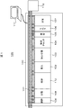
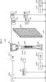
第1の実施例に係る生体試料の分析装置を、図1乃至図6を用いて説明する。図1は、第1の実施例に係る生体試料の分析装置の全体構成を示す構成図である。患者から採取した生体試料(血液)を前処理して、自動分析装置で分析する構成を示している。生体試料の分析装置120は、前処理システム100と、前処理システム100全体を制御する制御用PC111と、前処理システム100に接続された生体試料の成分を分析する自動分析装置112とから構成される。前処理システム100は、搬送ライン101、投入モジュール102、遠心分離モジュール103、検体チェックモジュール(検出装置)104、開栓モジュール105、バーコードなどのラベラ106、分注モジュール107、閉栓モジュール108、分類モジュール109、収納モジュール110を基本要素とする複数のモジュールからなる。
The biological sample analyzer according to the first embodiment will be described with reference to FIGS. FIG. 1 is a configuration diagram showing the overall configuration of the biological sample analyzer according to the first embodiment. A configuration is shown in which a biological sample (blood) collected from a patient is preprocessed and analyzed by an automatic analyzer. The biological sample analyzer 120 includes a pretreatment system 100, a control PC 111 that controls the entire pretreatment system 100, and an automatic analyzer 112 that analyzes components of the biological sample connected to the pretreatment system 100. The The pretreatment system 100 includes a transfer line 101, a loading module 102, a centrifuge module 103, a specimen check module (detection device) 104, an opening module 105, a labeler 106 such as a barcode, a dispensing module 107, a closing module 108, a classification It consists of a plurality of modules having the module 109 and the storage module 110 as basic elements.
投入モジュール102では、検体(血液が入った採血管)が投入され、遠心分離モジュール103では、投入された検体に対して遠心分離が施される。検体チェックモジュール104では、血清の種別・液量が検出される。開栓モジュール105では、遠心分離された検体の栓が開栓され、分注モジュール107では、遠心分離された検体を、自動分析装置112などで分析するために小分けされる。ラベラ106では、その小分けの容器にバーコードが貼り付けられる。閉栓モジュール108では、検体の栓が閉栓され、収納モジュール110では、閉栓された検体が収納される。分類モジュール109では、分注された検体容器が分類される。
In the input module 102, a sample (a blood collection tube containing blood) is input, and in the centrifuge module 103, the input sample is centrifuged. The specimen check module 104 detects the type and volume of serum. In the unplugging module 105, the centrifuged specimen is opened, and in the dispensing module 107, the centrifuged specimen is subdivided for analysis by the automatic analyzer 112 or the like. In the labeler 106, a barcode is attached to the subdivided container. The stopper module 108 closes the specimen plug, and the storage module 110 stores the stoppered specimen. In the classification module 109, the dispensed sample containers are classified.
検体の分析フローは以下の通りである。まず、採血管を用いて患者血液(全血)を採取する。当採血管は、前処理システム100の投入モジュール102に投入される。なお、採血と投入はユーザーのマニュアル作業で行い、以後の作業は前処理システム100による自動作業となる。なお、一般的には、採血は看護師が、投入は検査技師が行い、採血は、生体試料分析装置が設置される施設とは異なる施設で行われることもある。
Specimen analysis flow is as follows. First, patient blood (whole blood) is collected using a blood collection tube. The blood collection tube is input to the input module 102 of the pretreatment system 100. Blood collection and injection are performed manually by the user, and subsequent operations are automatic operations by the pretreatment system 100. In general, blood collection may be performed by a nurse, input is performed by a laboratory technician, and blood collection may be performed at a facility different from the facility where the biological sample analyzer is installed.
また、搬送作業は搬送ライン101が担う。投入された採血管は遠心分離モジュール103に運ばれ、そこで遠心分離が施される。採血管には予め分離剤が入っており、遠心分離により、相対的に比重の大きい血餅の層と、相対的に比重が小さく、血液分析に使用する血清の層に分離される。遠心分離された検体は、検体チェックモジュール104に運ばれ、血清の種別・液量が検出される。検出方法の詳細は後述する。血清の種別が溶血、黄疸、乳びと判断された検体は分類モジュール109に運ばれ、エラー検体として分類される。一方、血清の種別が正常と判断され、血清の液量が検出された検体は、開栓モジュール105に運ばれる。開栓モジュール105にて遠心分離された検体の栓が開栓され、分注モジュール107に運ばれる。同時に、ラベラ106でバーコードが貼付された小分けの容器も分注モジュール107に運ばれ、検体チェックモジュール104で検出した血清の液量情報をもとに、小分けの容器に検体が分注される。小分けが完了した検体は閉栓モジュール108に運ばれて検体の栓が閉栓され、収納モジュール110に収納される。収納された小分けの容器は自動分析装置112に運ばれ、各種成分分析が行われる。
Also, the transfer line 101 takes charge of the transfer work. The input blood collection tube is conveyed to the centrifuge module 103 where it is centrifuged. The blood collection tube contains a separating agent in advance, and is separated into a clot layer having a relatively large specific gravity and a serum layer having a relatively small specific gravity and used for blood analysis by centrifugation. The centrifuged sample is carried to the sample check module 104, and the type and amount of serum are detected. Details of the detection method will be described later. Samples whose serum types are determined to be hemolysis, jaundice, and chyle are conveyed to the classification module 109 and classified as error samples. On the other hand, the specimen whose serum type is determined to be normal and whose serum volume has been detected is carried to the unplugging module 105. The stopper of the sample centrifuged by the opening module 105 is opened and carried to the dispensing module 107. At the same time, the sub-container with the barcode attached by the labeler 106 is also carried to the dispensing module 107, and the sample is dispensed into the sub-container based on the serum volume information detected by the sample check module 104. . The sample for which the subdivision has been completed is transported to the closure module 108 where the specimen stopper is closed and stored in the storage module 110. The stored subdivided containers are transported to the automatic analyzer 112 for various component analysis.
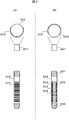
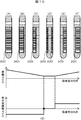
検体チェックモジュール104に運ばれる検体の採血管表面には、個人情報等が記載されたラベルが貼付されている。可視光をカメラで受光して血清の色、液量を検出する場合、ラベルの位置を考慮する必要がある。図2にカメラと採血管に貼られたラベルの向きとの関係図を示す。図2の上側の図面は上面図で、下側の図面は側面図である。図2(A)は、採血管(容器)202に貼られたラベル203がカメラ201側に向いた状態である。図2(B)は、採血管202に貼られたラベル203がカメラ201と反対側に向いた状態である。図2(A)ではラベルの影響によりカメラ201で血清領域の画像を撮像することはできず、図2(B)のようにラベル203とラベル203の隙間を通して撮像する必要がある。採血管202内の血液(試料)は、分離剤206によって、上部に血清(血清領域、第一の成分)204、下部に血餅(血餅領域、第二の成分)205と分離されている。採血管202には栓207がされている。
A label on which personal information and the like are written is affixed to the surface of the blood collection tube of the sample conveyed to the sample check module 104. When the visible color is received by the camera and the serum color and liquid volume are detected, it is necessary to consider the position of the label. FIG. 2 shows a relationship diagram between the camera and the direction of the label attached to the blood collection tube. The upper drawing of FIG. 2 is a top view, and the lower drawing is a side view. FIG. 2A shows a state in which the label 203 attached to the blood collection tube (container) 202 faces the camera 201 side. FIG. 2B shows a state in which the label 203 attached to the blood collection tube 202 faces away from the camera 201. In FIG. 2A, an image of the serum region cannot be captured by the camera 201 due to the influence of the label, and it is necessary to capture through the gap between the label 203 and the label 203 as shown in FIG. The blood (sample) in the blood collection tube 202 is separated from the serum (serum region, first component) 204 in the upper part and the clot (clot region, second component) 205 in the lower part by the separating agent 206. . The blood collection tube 202 has a stopper 207.
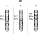
図3に血清領域と採血管表面に貼付されたラベルの位置の関係を示す。図3(A)のように、血清領域高さ方向全域にわたってラベル203aが貼付されている場合、図3(B)のように、血清領域高さ方向全域にわたってラベル203bが貼付されていない場合、図3(C)のように、血清領域高さ方向の一部にラベル203cが貼付されている場合がある。血清は透過率が高いことから、採血管の後方にある物体からの散乱光もカメラに入射する。そのため、カメラで撮像して得られる血清領域は、図3(A)の場合にはラベル203aを背景とする血清領域204Lのみ、図3(B)の場合には採血管後部に配置する背景板(背景部)を背景とする血清領域204Nのみとなるが、図3(C)の場合には、ラベル203cを背景とする血清領域204Lと背景板を背景とする血清領域204Nが混在することとなる。このとき、同じ血清であっても、カメラで撮像して得られる色はラベルを背景とする血清領域と背景板を背景とする血清領域との両領域間で異なる。
Fig. 3 shows the relationship between the serum area and the position of the label attached to the surface of the blood collection tube. As shown in FIG. 3A, when the label 203a is affixed over the entire serum region height direction, as shown in FIG. 3B, when the label 203b is not affixed throughout the serum region height direction, As shown in FIG. 3C, a label 203c may be attached to part of the serum region height direction. Since serum has a high transmittance, scattered light from an object behind the blood collection tube also enters the camera. Therefore, the serum region obtained by imaging with the camera is only the serum region 204L with the label 203a in the background in the case of FIG. 3A, and the background plate disposed at the rear of the blood collection tube in the case of FIG. In the case of FIG. 3C, the serum region 204L with the label 203c in the background and the serum region 204N with the background plate in the background are mixed. Become. At this time, even for the same serum, the color obtained by imaging with the camera differs between the serum area with the label as the background and the serum area with the background as the background.
ここで、背景板の色をラベルの色と同色とした場合、同じ血清種別であれば、ラベルを背景とする血清領域と背景板を背景とする血清領域で同じ色を得られる。しかし、背景板が黒色の場合を除いて、照明光が背景板で反射するため、採血管のキャップやラベルの影が血清領域に生じ、正常の血清と溶血・黄疸・乳びの血清との色の差が十分に得られない。そこで、照明光の反射を防ぐことができる黒色の背景板を用い、背景板がラベルと異なる色となる場合でも、血清の種別、液量を検出できる必要がある。そこで、第1の実施例、および後述する第2の実施例から第6の実施例では、以下の構成により黒色の背景板を用いた撮像を可能とし、ラベルの貼付/非貼付に関わらず血清の種別、液量を検出する。
Here, if the color of the background plate is the same as the color of the label, the same color can be obtained in the serum region with the background of the label and the serum region with the background of the background plate for the same serum type. However, except for the case where the background plate is black, the illumination light is reflected by the background plate, so the shadow of the blood collection tube cap or label occurs in the serum area, and normal serum and hemolyzed / jaundice / chyle serum A sufficient color difference cannot be obtained. Therefore, it is necessary to use a black background plate that can prevent reflection of illumination light, and to detect the type and volume of serum even when the background plate has a different color from the label. Therefore, in the first embodiment and the second to sixth embodiments described later, imaging using a black background plate is possible with the following configuration, and serum is applied regardless of whether the label is attached or not. Detect the type and amount of liquid.
背景板は、照明光の反射を防ぐことができるものが望ましい。具体的には、例えば、可視光領域の反射率が10%以下の背景板を用いる。また、背景板の色は、黒色に限るものではない。例えば、ラベルと補色関係にある色を用い、ラベル貼付/非貼付領域の区別を明確にすることを行ってもよい。
The background plate is preferably one that can prevent reflection of illumination light. Specifically, for example, a background plate having a visible light region reflectance of 10% or less is used. Further, the color of the background plate is not limited to black. For example, a color that is complementary to the label may be used to clarify the label application / non-application area.
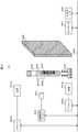
図4に第1の実施例の検体チェックモジュールの構成を示す。検体チェックモジュール(検出装置)104は、光源401a,401b、光源用ドライバ(ドライバ)402a,402b、カメラ(撮像部)201、画像処理エンジン(検知部)404、採血管ホルダ(保持部)405、背景板(背景部)406、コントローラ407、入出力インタフェース(入出力I/F)408、データバス409から構成される。
FIG. 4 shows the configuration of the sample check module of the first embodiment. The sample check module (detection device) 104 includes light sources 401a and 401b, light source drivers (drivers) 402a and 402b, a camera (imaging unit) 201, an image processing engine (detection unit) 404, a blood collection tube holder (holding unit) 405, A background plate (background portion) 406, a controller 407, an input / output interface (input / output I / F) 408, and a data bus 409 are included.
照射部である光源(照射要素)401a,401bは、それぞれ採血管202の前方上部および前方下部から光を照射する。光源401a,401bとしては、強度が強く、指向性の高い光であるLED光源などを用いる。波長の範囲はおおよそ、400nmから700nmの可視光を用いる。光源401a,401bを駆動するためには電源などの光源用ドライバ402a、402bを用いる。
The light sources (irradiation elements) 401a and 401b which are irradiation units irradiate light from the upper front and lower front of the blood collection tube 202, respectively. As the light sources 401a and 401b, LED light sources that are strong and have high directivity are used. The visible light having a wavelength range of approximately 400 nm to 700 nm is used. In order to drive the light sources 401a and 401b, light source drivers 402a and 402b such as a power source are used.
採血管202の前方上部および前方下部の上下から光を照射することで、ひとつの光源を用いる場合と比較し、採血管に当たる光の強度分布を一様にすることができる。光の強度分布を一様にすることにより、より正確に血清色情報を取得することができる。また、光源配置の別実施形態として、採血管202の前方左側および前方右側の左右から光を照射してもよい。前方左側および前方右側の左右からの照射により、採血管のキャップの影が血清領域に生じないため、正確に血清色情報を取得することができる。
By irradiating light from above and below the front upper portion and the lower front portion of the blood collection tube 202, the intensity distribution of light hitting the blood collection tube can be made uniform as compared with the case where one light source is used. By making the light intensity distribution uniform, the serum color information can be obtained more accurately. Further, as another embodiment of the light source arrangement, light may be irradiated from the left and right of the front left side and the front right side of the blood collection tube 202. Since the shadow of the cap of the blood collection tube does not occur in the serum region by irradiation from the left and right of the front left side and the front right side, the serum color information can be accurately acquired.
カメラ201では採血管202全体の2次元画像を撮像する。カメラ201と採血管202に貼られたラベル203の向きとの関係は、図2(B)のようにラベル203とラベル203の隙間から採血管202の中の試料を撮像できる状態とする。このとき、光源401a,401bから照射された光は採血管202を透過し、波長の一部は採血管202の中の血清204に吸収され、一部は血清204を透過する。透過した光は採血管202を透過して、採血管202表面に貼付されたラベル203上で散乱する。散乱した光は再度採血管202、血清204、採血管202の順に透過してカメラ201に入射する。画像処理エンジン404ではカメラ201で撮像された画像から血清領域抽出処理などの画像処理を行い、血清領域の位置、色を認識する。
The camera 201 captures a two-dimensional image of the entire blood collection tube 202. The relationship between the direction of the label 203 attached to the camera 201 and the blood collection tube 202 is such that the sample in the blood collection tube 202 can be imaged from the gap between the label 203 and the label 203 as shown in FIG. At this time, the light emitted from the light sources 401 a and 401 b is transmitted through the blood collection tube 202, a part of the wavelength is absorbed by the serum 204 in the blood collection tube 202, and a part is transmitted through the serum 204. The transmitted light is transmitted through the blood collection tube 202 and scattered on the label 203 attached to the surface of the blood collection tube 202. The scattered light is again transmitted through the blood collection tube 202, the serum 204, and the blood collection tube 202 in this order and enters the camera 201. The image processing engine 404 performs image processing such as serum region extraction processing from the image captured by the camera 201 to recognize the position and color of the serum region.
入出力インタフェース408はインタフェースとして用いられ、検出した血清の種別、量の表示やデータの伝送、血清の種別、量などに用いられるパラメータなどを制御用PC111から入力する際に用いる。コントローラ407は、検体チェックモジュール104の全体の制御を行う。
The input / output interface 408 is used as an interface, and is used when the detected serum type, amount display, data transmission, parameters used for the serum type, amount, etc. are input from the control PC 111. The controller 407 performs overall control of the sample check module 104.
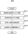
図5に第1の実施例に係る検体チェックモジュールの動作フローを示す。まずラベルの貼られた採血管202を採血管ホルダ405に設置する(ステップS501)。その後、採血管202全体をカメラ201で撮像する(ステップS502)。撮像された画像は、血清領域とラベルとの採血管軸方向の位置関係により図3(A)~(C)に示すような画像になる。カメラ201により撮像した画像は画像処理エンジン404により画像処理を行う(ステップS503)。画像処理によって検出した血清種別および血清量の情報を出力する(ステップS504)。
FIG. 5 shows an operation flow of the sample check module according to the first embodiment. First, the labeled blood collection tube 202 is placed in the blood collection tube holder 405 (step S501). Thereafter, the entire blood collection tube 202 is imaged by the camera 201 (step S502). The captured image is an image as shown in FIGS. 3A to 3C due to the positional relationship between the serum region and the label in the blood collection axis direction. The image picked up by the camera 201 is subjected to image processing by the image processing engine 404 (step S503). Information on the serum type and the serum amount detected by the image processing is output (step S504).
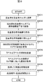
図6に画像処理のフローの一例を示す。まず取得した画像をRGB表色系からHSV表色系へ変換する(ステップS601)。HSV表色系は人間が色を知覚する方法と類似していることが知られており、従来人手で行っていた血清種別の認識を自動化する際に適している。HSV表色系に変換された画像を用い、ラベルを背景とする血清領域であるラベル貼付血清領域204Lを抽出する(ステップS602)。また、採血管202後部に設置の背景板406を背景とするラベル非貼付血清領域204Nの抽出も行う(ステップS603)。撮像した画像が、図3(A)に示すように、ラベルを背景とする血清領域302aのみの場合、ラベル非貼付血清領域204Nは抽出されない。また、図3(B)に示すように採血管202後部に配置する背景板406を背景とする血清領域301bのみの場合、ラベル貼付血清領域204Lは抽出されない。一方、図3(C)のように、ラベルを背景とする血清領域302cと背景板を背景とする血清領域301cが混在する場合、ラベル貼付血清領域204Lとラベル非貼付血清領域204Nの両方が抽出されることになる。
Fig. 6 shows an example of the image processing flow. First, the acquired image is converted from the RGB color system to the HSV color system (step S601). The HSV color system is known to be similar to the method of human perception of color, and is suitable for automating the recognition of serum types, which has been performed manually. Using the image converted to the HSV color system, a labeled serum region 204L, which is a serum region with the label as a background, is extracted (step S602). Further, the unlabeled serum region 204N with the background plate 406 installed at the rear of the blood collection tube 202 is extracted (step S603). As shown in FIG. 3A, when the captured image is only the serum region 302a with the label as the background, the unlabeled serum region 204N is not extracted. Further, as shown in FIG. 3B, in the case of only the serum region 301b with the background plate 406 arranged at the rear of the blood collection tube 202 as the background, the labeled serum region 204L is not extracted. On the other hand, as shown in FIG. 3C, when a serum region 302c with a label as a background and a serum region 301c with a background as a background coexist, both a labeled serum region 204L and a non-labeled serum region 204N are extracted. Will be.
ラベル貼付血清領域(第一の領域)204L、ラベル非貼付血清領域(第二の領域)204Nの抽出する方法としては、HSV表色系で特定の閾値を用いて抽出する方法が考えられる。具体的には、ラベルを背景とするラベル貼付血清領域204Lを抽出するHSV表色系の閾値、採血管202後部に設置の背景板406を背景とするラベル非貼付血清領域204Nを抽出するHSV表色系の閾値を、それぞれ設定しておき、閾値処理によってラベル貼付血清領域204Lおよびラベル非貼付血清領域204Nの各々の領域を抽出する。ラベル貼付血清領域204Lおよびラベル非貼付血清領域204Nの領域抽出に用いる閾値は、あらかじめ設定しておく方法が考えられる。また、採血管202の種類や、光源401a,401bの光量、カメラ201の設定値などにより変更してもよい。採血管202の種類によっては、壁面の材質が異なり、光の透過率が異なるため、同様な血清であった場合においても、カメラ201で撮像された画像での色は異なる場合がある。このため、領域抽出の閾値を採血管202の種類により変更することにより、より正確に血清領域204を抽出することができる。
As a method of extracting the labeled serum region (first region) 204L and the non-labeled serum region (second region) 204N, a method of extracting using a specific threshold value in the HSV color system is conceivable. Specifically, the HSV color system threshold for extracting the labeled serum region 204L with the label as the background, and the HSV table for extracting the non-labeled serum region 204N with the background plate 406 installed at the rear of the blood collection tube 202 as the background. Color system threshold values are set in advance, and each of the labeled serum region 204L and the non-labeled serum region 204N is extracted by threshold processing. A method is conceivable in which thresholds used for extracting the labeled serum region 204L and the unlabeled serum region 204N are set in advance. Further, it may be changed according to the type of the blood collection tube 202, the light amounts of the light sources 401a and 401b, the setting value of the camera 201, and the like. Depending on the type of the blood collection tube 202, the wall material is different and the light transmittance is different. Therefore, even in the case of similar serum, the color in the image captured by the camera 201 may be different. Therefore, the serum region 204 can be extracted more accurately by changing the region extraction threshold according to the type of the blood collection tube 202.
ラベル貼付血清領域204L、および、ラベル非貼付血清領域204Nを抽出した後に、血清の色情報の取得を行う(ステップS604)。ラベル貼付血清領域204Lとラベル非貼付血清領域204Nでの色は異なるため、いずれか一方の領域から色情報を抽出する。例えば、ラベル貼付血清領域204Lの色の平均値を血清の色として取得する。一般に血清領域の背面にラベルが貼付されている採血管が多いため、このようにラベル貼付血清領域204Lから色情報を取得することが有効である。
After extracting the labeled serum region 204L and the non-labeled serum region 204N, serum color information is acquired (step S604). Since the label-attached serum region 204L and the non-label-attached serum region 204N have different colors, color information is extracted from either one of the regions. For example, the average value of the color of the labeled serum region 204L is acquired as the serum color. In general, since there are many blood collection tubes with a label attached to the back of the serum region, it is effective to acquire color information from the labeled serum region 204L in this way.
なお、色情報の取得はこれに限るものでなく、ラベル非貼付領域204Nから色情報を取得してもよい。また、血清領域204とラベル203の位置関係により、どちらの領域から色情報を取得するか選択してもよい。例えば、図3(A)に示す位置関係の場合は、ラベル貼付領域204Lから、図3(B)に示す位置関係の場合は、ラベル非貼付血清領域204Nから色情報を取得してもよい。また、図3(C)に示す位置関係の場合は、いずれかの領域の色情報を取得してもよいし、領域が広い方の色情報を取得するなどをしてもよい。
The acquisition of color information is not limited to this, and the color information may be acquired from the label non-pasted area 204N. Further, depending on the positional relationship between the serum region 204 and the label 203, it may be selected from which region the color information is acquired. For example, in the case of the positional relationship shown in FIG. 3A, the color information may be acquired from the label attaching region 204L, and in the case of the positional relationship shown in FIG. 3B, the color information may be acquired from the non-labeled serum region 204N. In the case of the positional relationship shown in FIG. 3C, the color information of any region may be acquired, or the color information of the wider region may be acquired.
また、色情報の計算は、平均値を求めるとしたが、これに限るものではなく、中央値、分散などを取得することも考えられる。いずれにしても、ラベル貼付血清領域204L、ラベル非貼付血清領域204Nの情報を用い、色情報を取得する。
In addition, the calculation of the color information is to obtain the average value, but the present invention is not limited to this, and it is also possible to obtain the median value, variance, and the like. In any case, color information is acquired using information on the labeled serum region 204L and the non-labeled serum region 204N.
次に取得した色情報から血清種別を判定する(ステップS605)。血清種別の判定には閾値を用い、正常、溶血、黄疸、乳びなどの判定を行う。閾値はラベル203を背景として血清領域にあわせ、あらかじめ設定しておく。あらかじめ設定しておいた閾値と取得した血清の色情報を比較し、血清種別の判別を行う。
Next, the serum type is determined from the acquired color information (step S605). A threshold is used to determine the serum type, and normal, hemolysis, jaundice, chyle, etc. are determined. The threshold is set in advance according to the serum region with the label 203 as the background. The threshold value set in advance is compared with the color information of the acquired serum, and the serum type is determined.
また、同様に、採血管202後方の背景板406を背景とする血清領域にあわせ、血清種別の判定の閾値を持っておくことも有効である。図3(B)に示すようにラベル非貼付血清領域204Nのみの場合であっても血清種別を判別することが可能である。
Similarly, it is also effective to have a serum type determination threshold in accordance with the serum region with the background plate 406 behind the blood collection tube 202 as a background. As shown in FIG. 3B, it is possible to determine the serum type even in the case of only the non-labeled serum region 204N.
なお、血清種別判別のための閾値は、採血管202の種類や、光源401a,401bの光量、カメラ201の設定値などにより変更してもよい。採血管202の種類によっては、壁面の材質が異なり、光の透過率が異なるため、同様な血清であった場合においても、カメラ201で撮像された画像での色は異なる場合がある。このため、領域抽出の閾値を採血管の種類により変更することにより、より正確に血清種別を判別することが可能となる。
The threshold value for determining the serum type may be changed according to the type of the blood collection tube 202, the light amounts of the light sources 401a and 401b, the setting value of the camera 201, and the like. Depending on the type of the blood collection tube 202, the wall material is different and the light transmittance is different. Therefore, even in the case of similar serum, the color in the image captured by the camera 201 may be different. For this reason, it is possible to more accurately discriminate the serum type by changing the region extraction threshold according to the type of blood collection tube.
次に、血清量を算出するため、血清境界面の位置を取得する(ステップS606)。血清境界面の位置を取得するためには、血清領域の最上部および最下部を抽出する必要がある。従って、抽出したラベル貼付血清領域204L、および、ラベル非貼付血清領域204Nの両方の領域を使用する。具体的には、例えば、ラベル貼付、非貼付の両方の領域を結合した領域(結合領域)を算出し、結合領域とその上の領域(真空)の境界および結合領域とその下の領域(分離剤206)の境界の座標情報から血清境界面を取得する。取得した境界面の位置から、採血管202の直径などをパラメータとして用い、血清の量を算出する(ステップS607)。
Next, in order to calculate the serum amount, the position of the serum boundary surface is acquired (step S606). In order to acquire the position of the serum boundary surface, it is necessary to extract the top and bottom of the serum region. Therefore, both the extracted labeled serum region 204L and the unlabeled serum region 204N are used. Specifically, for example, an area (bonding area) obtained by combining both areas with and without labeling is calculated, and the boundary between the bonding area and the area above it (vacuum) and the bonding area and the area below it (separation) The serum boundary surface is obtained from the coordinate information of the boundary of the agent 206). From the acquired position of the boundary surface, the amount of serum is calculated using the diameter of the blood collection tube 202 as a parameter (step S607).
算出した血清種別および血清量の情報は、コントローラ407により制御され、入出力インタフェース408を通じて、制御用PC111に出力され(ステップS504)、エラー検体の除外や、液量不足の判別などに利用される。
Information on the calculated serum type and serum volume is controlled by the controller 407, and is output to the control PC 111 via the input / output interface 408 (step S504), and is used for excluding error specimens and determining insufficient liquid volume. .
このように、ラベル貼付血清領域、ラベル非貼付血清領域をそれぞれ抽出し、ラベル貼付血清領域から色情報を抽出することにより、正確に血清種別を判別することができる。また、ラベル貼付血清領域、ラベル非貼付血清領域の両領域から血清境界面を算出することで正確に血清量を取得することができる。本実施例の方法を用いることで、採血管軸方向のラベルの位置に依らず、正確に血清種別および血清量を取得することが可能となる。
Thus, the serum type can be accurately determined by extracting the labeled serum region and the non-labeled serum region, respectively, and extracting the color information from the labeled serum region. In addition, the amount of serum can be obtained accurately by calculating the serum boundary surface from both the labeled serum region and the unlabeled serum region. By using the method of the present embodiment, it is possible to accurately acquire the serum type and the serum amount regardless of the label position in the blood collection tube axial direction.
実施例1では、カメラと採血管に貼られたラベルの向きとの関係を、図2(B)のようにラベルとラベルの隙間から採血管の中の試料を撮像できる状態とした。しかし、採血管ホルダに設置されて検体チェックモジュールまで運ばれてきた検体が常に図2(B)の状態とは限らない。そこで本実施例では、カメラと採血管に貼られたラベルの向きとの関係がどのような状態であっても、図2(B)の状態の画像を取得する方法を説明する。なお、実施例2の生体試料の分析装置は、検体チェックモジュールを除き、実施例1の生体試料の分析装置120と基本的に同じである。
In Example 1, the relationship between the camera and the direction of the label affixed to the blood collection tube was set in a state where the sample in the blood collection tube could be imaged from the gap between the label as shown in FIG. However, the sample installed in the blood collection tube holder and carried to the sample check module is not always in the state of FIG. Therefore, in this embodiment, a method for acquiring the image in the state of FIG. 2B regardless of the state of the relationship between the camera and the direction of the label attached to the blood collection tube will be described. The biological sample analyzer of the second embodiment is basically the same as the biological sample analyzer 120 of the first embodiment except for the specimen check module.
図7に第2の実施例の検体チェックモジュールの構成を示す。検体チェックモジュール(検出装置)104Aは、光源401a,401b、光源用ドライバ402a、402b、カメラ(撮像部)201、画像処理エンジン(検知部)404、採血管ホルダ(保持部)405、背景板(背景部)406、コントローラ407、入出力インタフェース408、データバス409、把持機構701、移動機構702、上下制御ドライバ703、回転機構704、回転制御ドライバ705から構成される。
FIG. 7 shows the configuration of the sample check module of the second embodiment. The specimen check module (detection device) 104A includes light sources 401a and 401b, light source drivers 402a and 402b, a camera (imaging unit) 201, an image processing engine (detection unit) 404, a blood collection tube holder (holding unit) 405, a background plate ( (Background part) 406, controller 407, input / output interface 408, data bus 409, gripping mechanism 701, moving mechanism 702, vertical control driver 703, rotating mechanism 704, and rotation control driver 705.
照射部である光源(照射要素)401a,401bは、それぞれ採血管202の前方上部および前方下部から光を照射し、カメラ201では採血管202全体の2次元画像を撮像する。図2(A)のようにラベル203が採血管202表面のカメラ201側に貼付されている場合、光源401a,401bから照射された光は、採血管202表面に貼付されたラベル203上で散乱し、カメラ201に入射する。図2(B)のようにラベル203とラベル203の隙間から採血管202の中の試料を撮像できるときは、光源401a,401bから照射された光は採血管202を透過し、波長の一部は採血管202の中の血清204に吸収され、一部は血清204を透過する。透過した光は採血管202を透過して、採血管202表面に貼付されたラベル203上で散乱する。散乱した光は再度採血管202、血清204、採血管202の順に透過してカメラ201に入射する。画像処理エンジン404ではカメラ201で撮像された画像から血清領域抽出処理などの画像処理を行い、ラベル203の位置や血清領域204の位置、色を認識する。実施例1の別実施形態と同様に、採血管202の前方左側および前方右側の左右から光を照射してもよい。
Light sources (irradiation elements) 401a and 401b, which are irradiation units, irradiate light from the upper front and lower front of the blood collection tube 202, respectively, and the camera 201 captures a two-dimensional image of the entire blood collection tube 202. When the label 203 is affixed to the surface of the blood collection tube 202 on the camera 201 as shown in FIG. 2A, the light emitted from the light sources 401a and 401b is scattered on the label 203 affixed to the surface of the blood collection tube 202. Then, the light enters the camera 201. When the sample in the blood collection tube 202 can be imaged from the gap between the label 203 and the label 203 as shown in FIG. 2B, the light emitted from the light sources 401a and 401b passes through the blood collection tube 202 and a part of the wavelength. Is absorbed by the serum 204 in the blood collection tube 202, and part of the blood permeates the serum 204. The transmitted light is transmitted through the blood collection tube 202 and scattered on the label 203 attached to the surface of the blood collection tube 202. The scattered light is again transmitted through the blood collection tube 202, the serum 204, and the blood collection tube 202 in this order and enters the camera 201. The image processing engine 404 performs image processing such as serum region extraction processing from the image captured by the camera 201 to recognize the position of the label 203 and the position and color of the serum region 204. Similarly to the other embodiment of Example 1, light may be irradiated from the left and right of the front left side and the front right side of the blood collection tube 202.
把持機構701は、採血管ホルダ405に設置されて検体チェックモジュールまで運ばれてきた検体を把持して持ち上げ、検体全体がカメラ201の撮像範囲に収まるまで移動機構702により移動させる。上下移動は上下制御ドライバ(上下制御)703で制御される。採血管202を把持機構701で持ち上げることにより採血管202の下側からも十分に照明を当てるようにすることができる。採血管ホルダ405は搬送ラインにより搬送され、停止機構等により停止を制御されるため、採血管ホルダ405に採血管202を設置した状態では、停止機構等の影の影響があり、採血管202に一様に照明光を当てることが難しい。従って把持機構701で採血管202を持ち上げ、照明を採血管202に一様に当てられるようにする。
The gripping mechanism 701 grips and lifts the specimen that has been installed in the blood collection tube holder 405 and carried to the specimen check module, and moves the whole specimen by the moving mechanism 702 until it falls within the imaging range of the camera 201. Vertical movement is controlled by a vertical control driver (vertical control) 703. By lifting the blood collection tube 202 with the gripping mechanism 701, it is possible to sufficiently illuminate from the lower side of the blood collection tube 202. Since the blood collection tube holder 405 is conveyed by the conveyance line and is controlled to stop by a stop mechanism or the like, in the state where the blood collection tube 202 is installed on the blood collection tube holder 405, there is an influence of the shadow of the stop mechanism or the like, It is difficult to apply illumination light uniformly. Therefore, the blood collection tube 202 is lifted by the gripping mechanism 701 so that illumination can be uniformly applied to the blood collection tube 202.
把持機構701で持ち上げた検体は、回転機構704により回転させ、採血管202表面に貼付されたラベル203とカメラ201との位置関係を変えて、カメラ201が採血管202を一周撮像できるようにする。把持機構701および回転機構704により回転部を構成する。回転は回転制御ドライバ705で制御される。入出力インタフェース408はインタフェースとして用いられ、検出した血清の種別、量の表示やデータの伝送、血清の種別、量などに用いられるパラメータなどを入力する際に用いる。
The specimen lifted by the gripping mechanism 701 is rotated by the rotating mechanism 704, and the positional relationship between the label 203 attached to the surface of the blood collection tube 202 and the camera 201 is changed so that the camera 201 can image the blood collection tube 202 once. . The gripping mechanism 701 and the rotation mechanism 704 constitute a rotation unit. The rotation is controlled by a rotation control driver 705. The input / output interface 408 is used as an interface, and is used to input parameters and the like used for displaying the detected serum type and amount, transmitting data, and the type and amount of serum.
図8に実施例2の検体チェックモジュールの動作フローを示す。まずラベルの貼られた採血管202を採血管ホルダ405に設置する(ステップS801)。その後、採血管202を採血管ホルダ405ごと把持機構701直下まで移動させる(ステップS802)。採血管202を把持機構701で把持し(ステップS803)、採血管202全体をカメラ201で撮像できる位置まで持ち上げて(ステップS804)、回転させながらカメラ201で画像を複数枚取得する(ステップS805)。取得した画像から、画像処理エンジン404においてラベルとラベルの隙間を認識する(ステップS806)。
FIG. 8 shows an operation flow of the sample check module of the second embodiment. First, the labeled blood collection tube 202 is placed in the blood collection tube holder 405 (step S801). Thereafter, the blood collection tube 202 is moved together with the blood collection tube holder 405 to just below the gripping mechanism 701 (step S802). The blood collection tube 202 is grasped by the grasping mechanism 701 (step S803), the entire blood collection tube 202 is lifted to a position where it can be imaged by the camera 201 (step S804), and a plurality of images are acquired by the camera 201 while being rotated (step S805). . From the acquired image, the image processing engine 404 recognizes the gap between the labels (step S806).
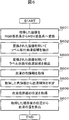
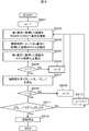
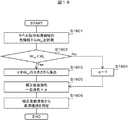
図9にラベルとラベルの隙間認識フローの一例を示す。図10は第2の実施例に係る採血管の向き変化に伴うラベルの面積変化を示す説明図である。本フローは画像を1枚取得する度に実施する。まず第1番目に取得した画像をRGB表色系からHSV表色系へ変換する(ステップS902)。閾値処理で図10(A)に示すようにラベル203を抽出する(ステップS903)。ラベルを抽出するHSV表色系の閾値はあらかじめ設定しておく。抽出したラベルの領域からラベルの面積(S1)を算出する(ステップS904)。次に第2番目に取得した画像から第1番目に取得した画像同様、ラベルの面積(S2)を算出する(ステップS904)。その後、第1番目に取得した画像におけるラベルの面積から、第2番目に取得した画像におけるラベルの面積の面積変化率(ΔS2)を算出する(ステップS907)。第3番目以降に取得した画像も同様に面積変化率(ΔSn)を算出する(ステップS907)。なお、ステップS901は第1番目に取得した画像についての処理を行うためnに1を代入する。面積変化率(ΔSn)は、第2番目の画像を取得した後でなければ算出できないので、ステップS905で第2番目以降かどうかを判定する。ステップS906は第2番目に取得した画像についての処理を行うためnに2を代入する。ステップS909は第3番目に取得した画像についての処理を行うためnに3を代入する。
FIG. 9 shows an example of a label-to-label gap recognition flow. FIG. 10 is an explanatory diagram showing changes in the area of the label accompanying changes in the direction of the blood collection tube according to the second embodiment. This flow is performed every time one image is acquired. First, the first acquired image is converted from the RGB color system to the HSV color system (step S902). As shown in FIG. 10A, the label 203 is extracted by the threshold processing (step S903). The threshold of the HSV color system for extracting labels is set in advance. The label area (S 1 ) is calculated from the extracted label region (step S904). Next, as with the first acquired image, the label area (S 2 ) is calculated from the second acquired image (step S904). Thereafter, the area change rate (ΔS 2 ) of the label area in the second acquired image is calculated from the area of the label in the first acquired image (step S907). Similarly, the area change rate (ΔS n ) is calculated for the third and subsequent images (step S907). In step S901, 1 is substituted for n in order to perform processing for the first acquired image. Since the area change rate (ΔS n ) can be calculated only after the second image is acquired, it is determined in step S905 whether it is the second or later. In step S906, 2 is substituted for n in order to perform processing for the second acquired image. In step S909, 3 is substituted for n in order to perform processing for the third acquired image.
図10(G)に面積変化率の推移を示す。横軸は、図10(A)から図10(F)に相当する採血管202の角度、縦軸はラベル面積およびラベル面積変化率である。図10(A)の状態のラベル面積が一番大きく、図10(D)の状態のラベル面積が一番小さい。ラベル面積は、図10(A)から図10(D)に向かうにつれて小さくなり、図10(D)から図10(F)に向かうにつれて大きくなる。面積変化率(ΔSn)の符号が負から正に反転したとき、ラベルとラベルの隙間がカメラ201側に向いたと判断し(ステップS911)、回転を停止する(ステップS912)。なお、ステップS911の判定は、第3番目以降の画像を取得した後でなければすえることができないので、ステップS908で第3番目以降かどうかを判定する。ステップS909は第3番目に取得した画像についての処理を行うためnに3を代入する。ステップS910は第4番目以降に取得した画像についての処理を行うためnをインクリメントする。最後に取得した(ステップS807)画像から、閾値処理によってラベル203を背景とするラベル貼付血清領域204L、採血管202後部に設置の背景板406を背景とするラベル非貼付血清領域204Nを抽出する。抽出したラベル貼付血清領域204Lおよびラベル非貼付血清領域204Nから、実施例1と同様に、血清種別の判別、血清量の算出を行い(ステップS808)、その結果を出力する(ステップS809)。
FIG. 10G shows the transition of the area change rate. The horizontal axis represents the angle of the blood collection tube 202 corresponding to FIGS. 10A to 10F, and the vertical axis represents the label area and the label area change rate. The label area in the state of FIG. 10 (A) is the largest, and the label area in the state of FIG. 10 (D) is the smallest. The label area decreases from FIG. 10A to FIG. 10D and increases from FIG. 10D to FIG. 10F. When the sign of the area change rate (ΔS n ) is reversed from negative to positive, it is determined that the gap between the labels is directed to the camera 201 (step S911), and the rotation is stopped (step S912). Note that since the determination in step S911 can be made only after the third and subsequent images are acquired, it is determined in step S908 whether or not it is the third and subsequent images. In step S909, 3 is substituted for n in order to perform processing for the third acquired image. In step S910, n is incremented to perform processing for the fourth and subsequent images. Finally, a label-attached serum region 204L with the label 203 as a background and a non-label-attached serum region 204N with a background plate 406 installed at the rear of the blood collection tube 202 are extracted from the acquired image (step S807) by threshold processing. From the extracted labeled serum region 204L and unlabeled serum region 204N, the serum type is determined and the serum amount is calculated in the same manner as in Example 1 (step S808), and the result is output (step S809).
本実施例に示すように、採血管202を回転させながら画像を撮像し、カメラ201側にラベル203とラベル203の隙間を向けることにより、カメラ201と採血管202に貼られたラベル203の向きとの関係がどのような状態であっても、図2(B)の状態の画像を取得し、ラベル203を背景とするラベル貼付血清領域204L、採血管202後部に設置の背景板406を背景とするラベル非貼付血清領域204Nを抽出することができる。
As shown in this embodiment, the direction of the label 203 attached to the camera 201 and the blood collection tube 202 is obtained by capturing an image while rotating the blood collection tube 202 and directing the gap between the label 203 and the label 203 toward the camera 201 side. 2B, an image of the state shown in FIG. 2B is acquired, and the background of the labeled plate serum region 204L with the label 203 as the background and the background plate 406 installed at the rear of the blood collection tube 202 is obtained. An unlabeled serum region 204N can be extracted.
なお、本実施例では、ラベル203とラベル203の隙間がカメラ201側に向いたと判断した場合に回転を停止するとしたが、これに限るものではない。採血管202を360度回転させながら画像を複数毎撮像しておき、撮像した画像からカメラ201側に向いた画像を選択してもよい。回転をリアルタイムに停止制御する必要がなくなるため、制御に時間がかかる場合などに適している。
In this embodiment, the rotation is stopped when it is determined that the gap between the label 203 and the label 203 faces the camera 201 side, but the present invention is not limited to this. A plurality of images may be captured while rotating the blood collection tube 202 360 degrees, and an image facing the camera 201 may be selected from the captured images. Since it is not necessary to stop and control the rotation in real time, it is suitable when the control takes time.
また、ラベルの面積変化率からラベル203の隙間がカメラ201側に向いたと判断するとしたが、これに限るものではない。例えば、血清領域の面積が最大になる画像を抽出し、ラベル203の隙間がカメラ201側に向いたと判断してもよい。
Further, although it is determined that the gap of the label 203 is directed toward the camera 201 from the area change rate of the label, the present invention is not limited to this. For example, an image that maximizes the area of the serum region may be extracted, and it may be determined that the gap between the labels 203 faces the camera 201 side.
実施例2では、回転させながらカメラ201で画像を複数枚取得して、図2(B)の状態の画像を取得した。本実施例では、ラインカメラを用いることによって、1枚の画像から図2(B)と同等の状態の画像を取得する方法を説明する。なお、実施例3の生体試料の分析装置は、検体チェックモジュールを除き、実施例1の生体試料の分析装置120と基本的に同じである。
In Example 2, a plurality of images were acquired with the camera 201 while rotating, and the image in the state of FIG. 2B was acquired. In this embodiment, a method for acquiring an image in a state equivalent to that in FIG. 2B from one image by using a line camera will be described. The biological sample analyzer of the third embodiment is basically the same as the biological sample analyzer 120 of the first embodiment except for the specimen check module.
図20に第3の実施例の検体チェックモジュールの構成を示す。本実施例の検体チェックモジュール104Bでは、実施例2と同様の構成で、カメラ(エリアカメラ)201の変わりにラインカメラ201Lを用いる。実施例2と同様に、採血管202の前方左側および前方右側の左右から光を照射してもよい。
FIG. 20 shows the configuration of the sample check module of the third embodiment. In the sample check module 104B of the present embodiment, a line camera 201L is used instead of the camera (area camera) 201 with the same configuration as that of the second embodiment. Similarly to the second embodiment, light may be emitted from the left and right front left and front right of the blood collection tube 202.
図11に実施例3の検体チェックモジュールの動作フローを示す。まずラベル203の貼られた採血管202を採血管ホルダ405に設置する(ステップS1101)。その後、採血管202を採血管ホルダ405ごと把持機構701直下まで移動させる(ステップS1102)。採血管202を把持機構701で把持し(ステップS1103)、採血管202全体をカメラ201Lで撮像できる位置まで持ち上げて(ステップS1104)、回転させながらラインカメラ201Lで採血管202の1周分の画像を1枚取得する(ステップS1105)。取得した画像から、画像処理エンジン404においてラベル203とラベル203の隙間を認識する(ステップS1106)。
FIG. 11 shows an operation flow of the sample check module according to the third embodiment. First, the blood collection tube 202 to which the label 203 is attached is placed on the blood collection tube holder 405 (step S1101). Thereafter, the blood collection tube 202 is moved together with the blood collection tube holder 405 to directly below the gripping mechanism 701 (step S1102). The blood collection tube 202 is grasped by the grasping mechanism 701 (step S1103), the whole blood collection tube 202 is lifted to a position where it can be imaged by the camera 201L (step S1104), and the image for one round of the blood collection tube 202 is rotated by the line camera 201L while rotating. Is obtained (step S1105). From the acquired image, the image processing engine 404 recognizes the gap between the label 203 and the label 203 (step S1106).
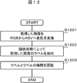
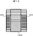
図12にラベルとラベルの隙間認識フローの一例を示す。また、図13にラインカメラにより撮像される画像の一例を示す。まず取得した画像をRGB表色系からHSV表色系へ変換する(ステップS1201)。ラベルを抽出するHSV表色系の閾値はあらかじめ設定しておき、閾値処理でラベル203を抽出する(ステップS1202)。ラベル203の抽出結果から、ラベル203とラベル203の隙間1302を認識する(ステップS1203)。その後、実施例2の方法と同様に、血清色、量の検出を行い、結果を出力する(ステップS1107)。
Fig. 12 shows an example of a flow for recognizing labels between labels. FIG. 13 shows an example of an image captured by the line camera. First, the acquired image is converted from the RGB color system to the HSV color system (step S1201). The threshold of the HSV color system for extracting the label is set in advance, and the label 203 is extracted by threshold processing (step S1202). From the extraction result of the label 203, the gap 1302 between the label 203 and the label 203 is recognized (step S1203). Thereafter, similar to the method of the second embodiment, the serum color and amount are detected, and the result is output (step S1107).
本実施例に示すように、ラインカメラを用いて検体1周分の画像を撮像することにより、1枚の画像で処理が可能となり、ラベルの面積を算出する処理をなくすことができるため、処理時間を短縮することができる。
As shown in the present embodiment, by capturing an image for one round of the sample using a line camera, processing can be performed with one image, and processing for calculating the area of the label can be eliminated. Time can be shortened.
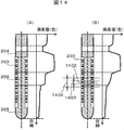
検体によっては血清-分離剤間界面および血餅-分離剤界面がカメラ側から見て奥行き方向に傾きをもつことがある。図14に採血管軸方向の色の変化率の一例を示す。界面が傾きをもたない場合、採血管軸方向の色の変化率は図14(A)のようになるのに対し、界面がカメラ側から見て奥行き方向に傾きをもつ場合、採血管軸方向の色の変化率は図14(B)のように、界面が傾きをもたない場合に比べて小さくなり、血餅-分離剤間界面の位置を誤認識する可能性がある。図14(A)および図14(B)では血餅-分離剤界面について示したが、血清-分離剤界面でも同様である。そのため、本実施例では、界面付近の色の変化率がある閾値を下回る場合、カメラから見て奥行き方向に界面が傾いているものとして、別のある閾値を上回る色の変化率が生じる位置を界面とする。なお、本実施例は実施例2の生体試料の分析装置の検体チェックモジュールに基づいて説明する。
Depending on the specimen, the serum-separation agent interface and the clot-separation agent interface may be inclined in the depth direction when viewed from the camera side. FIG. 14 shows an example of the color change rate in the direction of the blood collection tube axis. When the interface has no inclination, the color change rate in the direction of the blood collection tube axis is as shown in FIG. 14A, whereas when the interface has an inclination in the depth direction when viewed from the camera side, As shown in FIG. 14B, the direction color change rate is smaller than that in the case where the interface has no inclination, and the position of the clot-separating agent interface may be erroneously recognized. 14A and 14B show the clot-separating agent interface, the same applies to the serum-separating agent interface. Therefore, in this embodiment, when the color change rate in the vicinity of the interface is below a certain threshold, the position where the color change rate exceeds another certain threshold is determined assuming that the interface is inclined in the depth direction when viewed from the camera. Let it be an interface. In addition, a present Example demonstrates based on the sample check module of the analyzer of the biological sample of Example 2. FIG.
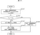
図15に色の変化率を利用した血清-分離剤間界面の検出フローを示す。まず採血管202を把持機構701で回転させながらカメラ201で画像を取得する。画像処理エンジン404によりラベル203とラベル203の隙間を認識し、ラベルを背景とするラベル貼付血清領域204L、採血管202後部に設置の背景板406を背景とするラベル非貼付血清領域204Nを各々抽出する。その後、ラベル貼付血清領域204Lおよびラベル非貼付血清領域204Nの色情報から血清液面、血清-分離剤間界面を検出し、図14(B)に示すように、血餅-分離剤間界面の軸1402から±a画素(pixel)分1403の採血管軸方向の色の変化率(Δca)を算出するのと同様に、血清-分離剤間界面の軸から±a画素分の採血管軸方向の色の変化率(Δca)を算出する(ステップS1501)。色の変化率(Δca)と閾値(Δct1)とを比較し(ステップS1502)、色の変化率(Δca)が閾値(Δct1)より大きい場合、血清-分離剤間界面の傾きはないと判断する(ステップS1503)。色の変化率(Δca)が閾値(Δct1)より小さい場合、図14(B)に示すように、さらに周辺1404の色の変化率(Δcs)を算出するのと同様に、血清-分離剤間界面の軸から±a画素分の周辺の色の変化率(Δcs)を算出し(ステップS1504)、色の変化率(Δcs)が閾値(Δct2)より小さくなった位置を血清-分離剤間界面とする(ステップS1505)。
FIG. 15 shows a detection flow of the interface between the serum and the separating agent using the color change rate. First, an image is acquired by the camera 201 while the blood collection tube 202 is rotated by the gripping mechanism 701. The image processing engine 404 recognizes the gap between the label 203 and the label 203, and extracts a label-attached serum region 204L with the label as a background and a non-label-attached serum region 204N with a background plate 406 installed at the rear of the blood collection tube 202 as a background. To do. Thereafter, the serum liquid level and the interface between the serum and the separating agent are detected from the color information of the labeled serum region 204L and the non-labeled serum region 204N. As shown in FIG. Similar to calculating the color change rate (Δca) in the direction of blood collection tube for ± a pixels 1403 from the axis 1402, the direction of the blood collection tube axis for ± a pixels from the axis of the serum-separating agent interface The color change rate (Δca) is calculated (step S1501). The color change rate (Δca) and the threshold value (Δct1) are compared (step S1502). If the color change rate (Δca) is greater than the threshold value (Δct1), it is determined that there is no inclination of the serum-separating agent interface. (Step S1503). When the color change rate (Δca) is smaller than the threshold value (Δct1), as shown in FIG. 14B, the color change rate (Δcs) of the peripheral 1404 is calculated in the same manner as shown in FIG. 14B. The change rate (Δcs) of the color around ± a pixels from the interface axis is calculated (step S1504), and the position where the color change rate (Δcs) is smaller than the threshold value (Δct2) is determined as the serum-separation agent interface. (Step S1505).
本実施例によって、血清-分離剤間などの界面がカメラ側から見て奥行き方向に傾きを持つ場合でも、採血管軸方向の色の変化率を利用することによって、界面の位置を認識することができる。なお、本実施例は実施例3の生体試料の分析装置の検体チェックモジュールにも適用することができる。
According to this embodiment, even when the interface between the serum and the separating agent has an inclination in the depth direction when viewed from the camera side, the position of the interface is recognized by using the color change rate in the blood collection axis direction. Can do. This embodiment can also be applied to the sample check module of the biological sample analyzer of the third embodiment.
エリアカメラ、ラインカメラのどちらで採血管を撮像した場合でも、ラベルとラベルの隙間幅の大きさは、ラベルの大きさと採血管径との関係によって異なる。隙間幅の大きさに依存してカメラ側に貼付されたラベル幅の大きさは変化する。カメラ側に貼付されたラベル幅の大きさによって、光源からの光が採血管、血清を透過してラベル上で散乱し、血清、採血管を再透過する光量が異なること、血清領域に生じるラベルの影面積が異なることから、同じ血清の種別でも、カメラで撮像して得られる色は異なる。そのため、本実施例では、ラベルとラベルの隙間幅の大きさをパラメータとして血清領域の色を判定する方法を説明する。なお、本実施例は実施例2および実施例3の生体試料の分析装置の検体チェックモジュールに基づいて説明する。
Whether a blood collection tube is imaged by either an area camera or a line camera, the size of the label-to-label gap width varies depending on the relationship between the label size and the blood collection tube diameter. Depending on the size of the gap width, the size of the label width attached to the camera side changes. Depending on the size of the label affixed to the camera side, the light from the light source passes through the blood collection tube and serum and scatters on the label, and the amount of light that retransmits the serum and blood collection tube differs, and the label generated in the serum region Therefore, even if the serum type is the same, the color obtained by imaging with the camera is different. Therefore, in the present embodiment, a method for determining the color of the serum region using the size of the gap width between the labels as a parameter will be described. In addition, a present Example demonstrates based on the sample check module of the biological sample analyzer of Example 2 and Example 3. FIG.
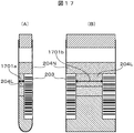
図16、図17にラベルとラベルの隙間幅の大きさをパラメータとした血清領域の色判定フローおよび説明図を示す。図17(A)はエリアカメラで撮像した画像で、図17(B)はラインカメラで撮像した画像である。まず採血管202を把持機構701で回転させながらカメラ201,201Lで画像を取得する。画像処理エンジン404によりラベル203とラベル203の隙間を認識し、ラベル203を背景とするラベル貼付血清領域204L、採血管202後部に設置の背景板406を背景とするラベル非貼付血清領域204Nを各々抽出する。その後、図17(A)および図17(B)に示すように、ラベル貼付血清領域204Lの色情報からラベル203とラベル203の隙間幅(Wm)1701a、1701bを計測する(ステップS1601)。隙間幅(Wm)1701a、1701bと閾値(Wt)とを比較し(ステップS1602)、隙間幅(Wm)1701a、1701bが閾値(Wt)より小さい場合、血清の色にかける補正係数(α)を隙間幅(Wm)1701a、1701bの大きさから算出する(ステップS1603)。隙間幅(Wm)1701a、1701bが閾値(Wt)より大きい場合、血清の色にかける補正係数(α)は1とする(ステップS1604)。血清の色に補正係数(α)をかけて補正後血清色を算出し(ステップS1605)、補正後血清色から血清の種別を判定する(ステップS1606)。なお、本実施例で説明した補正の計算式は一例であり、他の計算式に従って補正を行ってもよい。
FIG. 16 and FIG. 17 show the color determination flow and explanatory diagram of the serum region using the size of the gap width between the labels as a parameter. FIG. 17A is an image captured by an area camera, and FIG. 17B is an image captured by a line camera. First, images are acquired by the cameras 201 and 201L while the blood collection tube 202 is rotated by the gripping mechanism 701. A gap between the label 203 and the label 203 is recognized by the image processing engine 404, and a label-attached serum region 204L with the label 203 as a background and a non-label-attached serum region 204N with a background plate 406 installed at the rear of the blood collection tube 202 as a background Extract. Thereafter, as shown in FIGS. 17A and 17B, the gap widths (Wm) 1701a and 1701b between the label 203 and the label 203 are measured from the color information of the labeled serum region 204L (step S1601). The gap widths (Wm) 1701a and 1701b are compared with the threshold value (Wt) (step S1602). If the gap widths (Wm) 1701a and 1701b are smaller than the threshold value (Wt), the correction coefficient (α) applied to the serum color is calculated. The gap width (Wm) is calculated from the sizes of 1701a and 1701b (step S1603). When the gap widths (Wm) 1701a and 1701b are larger than the threshold value (Wt), the correction coefficient (α) applied to the serum color is set to 1 (step S1604). The corrected serum color is calculated by multiplying the serum color by the correction coefficient (α) (step S1605), and the type of serum is determined from the corrected serum color (step S1606). The correction calculation formula described in the present embodiment is an example, and correction may be performed according to another calculation formula.
本実施例によって、ラベルとラベルの隙間幅の大きさによらず、血清の種別を判定することができる。また、本実施例では、ラベルとラベルの隙間幅のうち採血管径方向について説明したが、採血管軸方向についても同様の考え方によって血清の種別を判定することができる。
According to the present embodiment, the type of serum can be determined regardless of the size of the gap width between the labels. In the present embodiment, the blood collection tube radial direction in the gap width between the labels has been described, but the serum type can also be determined based on the same concept in the blood collection tube axial direction.
エリアカメラで採血管を回転させながら複数枚画像を取得するとき、採血管の向きによって、カメラ側に貼付されたラベル幅の大きさは変化する。カメラ側に貼付されたラベル幅の大きさによって、光源からの光が採血管、血清を透過してラベル上で散乱し、血清、採血管を再透過する光量が異なること、血清領域に生じるラベルの影面積が異なることから、同じ血清の種別でも、カメラで撮像して得られる色は異なる。そのため、本実施例では、採血管の向きをパラメータとして血清領域の色を判定する方法を説明する。なお、本実施例は実施例2の生体試料の分析装置の検体チェックモジュールに基づいて説明する。
When acquiring multiple images while rotating a blood collection tube with an area camera, the size of the label width affixed to the camera side changes depending on the direction of the blood collection tube. Depending on the size of the label affixed to the camera side, the light from the light source passes through the blood collection tube and serum and scatters on the label, and the amount of light that retransmits the serum and blood collection tube differs, and the label generated in the serum region Therefore, even if the serum type is the same, the color obtained by imaging with the camera is different. Therefore, in the present embodiment, a method for determining the color of the serum region using the direction of the blood collection tube as a parameter will be described. In addition, a present Example demonstrates based on the sample check module of the analyzer of the biological sample of Example 2. FIG.
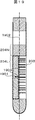
図18、図19に採血管の向きをパラメータとした血清領域の色判定フローおよび説明図を示す。まず採血管202を把持機構701で回転させながらカメラ201で画像を取得する。画像処理エンジン404によりラベル203とラベル203の隙間を認識し、ラベル203を背景とするラベル貼付血清領域204L、採血管202後部に設置の背景板406を背景とするラベル非貼付血清領域204Nを各々抽出する。その後、図19に示すようにラベル貼付血清領域204Lの色情報からラベル203とラベル203の隙間領域の重心1901と採血管軸1902との距離(Dm)1903を計測する(ステップS1801)。距離(Dm)1903と閾値(Dt)とを比較し(ステップS1802)、距離(Dm)1903が閾値(Dt)より大きい場合、血清の色にかける補正係数(α)を距離(Dm)1903から算出する(ステップS1803)。距離(Dm)1903が閾値(Dt)より小さい場合、補正係数(α)は1とする(ステップS1804)。血清の色に補正係数(α)をかけて補正後血清色を算出し(ステップS1805)、補正後血清色から血清の種別を判定する(ステップS1806)。なお、本実施例で説明した補正の計算式は一例であり、他の計算式に従って補正を行ってもよい。
FIG. 18 and FIG. 19 show the color determination flow and explanatory diagram of the serum region using the direction of the blood collection tube as a parameter. First, an image is acquired by the camera 201 while the blood collection tube 202 is rotated by the gripping mechanism 701. A gap between the label 203 and the label 203 is recognized by the image processing engine 404, and a label-attached serum region 204L with the label 203 as a background and a non-label-attached serum region 204N with a background plate 406 installed at the rear of the blood collection tube 202 as a background Extract. Then, as shown in FIG. 19, the distance (Dm) 1903 between the center of gravity 1901 of the gap region between the label 203 and the label 203 and the blood collection tube axis 1902 is measured from the color information of the labeled serum region 204L (step S1801). The distance (Dm) 1903 is compared with the threshold value (Dt) (step S1802). When the distance (Dm) 1903 is larger than the threshold value (Dt), the correction coefficient (α) applied to the serum color is calculated from the distance (Dm) 1903. Calculate (step S1803). When the distance (Dm) 1903 is smaller than the threshold value (Dt), the correction coefficient (α) is set to 1 (step S1804). The corrected serum color is calculated by multiplying the serum color by the correction coefficient (α) (step S1805), and the type of serum is determined from the corrected serum color (step S1806). The correction calculation formula described in the present embodiment is an example, and correction may be performed according to another calculation formula.
背景板の色として、例えば照明光の反射を防ぐ黒色を選ぶことによって、採血管のキャップやラベルの影が血清領域に生じるのを抑える効果が得られる。しかし、明度の低い黄疸(暗黄色)などの検体を撮影する場合、ラベル非貼付血清領域と背景板との色の差が十分に得られず、血清領域を誤抽出することがある。そのため、本実施例では、明度の低い検体の撮影にも適用可能とするために、明度の高い色、例えば白色の背景板を用いる方法を説明する。
白色の背景板は反射率が高いため、背景板での正反射光を低減する処理を施す必要がある。例えば、ポリカーボネイトを白色で塗装した素材を貼り付ける方法がある。また、艶消し処理を施したり、正反射の起こりにくい表面性状となるように表面を加工したりすることも有効である。
本実施例によって、白色の背景板を用いた場合でも、背景板での正反射光を低減し、血清の種別、液量の検出が可能な画像を取得することができる。
ここでは、白色を中心として説明したが、厳密な白色でなければいけないわけではなく、明度の低い検体に対して、所定以上の明度の差を有する色であればよいことは言うまでもない。なお、本実施例は実施例1から実施例3の生体試料の分析装置の検体チェックモジュールに適用することができる。また、実施例4から実施例6を用いる検体チェックモジュールにも適用することができる。 For example, by selecting a black color that prevents reflection of illumination light as the color of the background plate, an effect of suppressing the shadow of the blood collection cap or label in the serum region can be obtained. However, when a specimen such as jaundice (dark yellow) with low lightness is photographed, a sufficient color difference between the unlabeled serum area and the background plate cannot be obtained, and the serum area may be erroneously extracted. Therefore, in this embodiment, a method using a color with a high brightness, for example, a white background plate, will be described in order to be applicable to imaging of a specimen with a low brightness.
Since the white background plate has a high reflectance, it is necessary to perform processing for reducing regular reflection light on the background plate. For example, there is a method of pasting a material in which polycarbonate is painted in white. It is also effective to apply a matte treatment or to process the surface so that the surface properties are less likely to cause regular reflection.
According to the present embodiment, even when a white background plate is used, it is possible to reduce the specular reflection light on the background plate and obtain an image capable of detecting the type of serum and the amount of liquid.
Here, the description has been made centering on white, but it does not have to be strictly white, and it is needless to say that the color having a lightness difference of a predetermined level or more for a low-lightness specimen may be used. The present embodiment can be applied to the sample check module of the biological sample analyzer of the first to third embodiments. Further, the present invention can be applied to the sample check module using the fourth to sixth embodiments.
以上、本発明者によってなされた発明を実施の形態および実施例に基づき具体的に説明したが、本発明は前記実施の形態および実施例に限定されるものではなく、その要旨を逸脱しない範囲で種々変更可能であることはいうまでもない。
As mentioned above, the invention made by the present inventor has been specifically described based on the embodiments and examples. However, the present invention is not limited to the above-described embodiments and examples, and does not depart from the spirit of the invention. It goes without saying that various changes can be made.
100…前処理システム
101…搬送ライン
102…投入モジュール
103…遠心分離モジュール
104、104A、104B…検体チェックモジュール
105…開栓モジュール
106…ラベラ
107…分注モジュール
108…閉栓モジュール
109…分類モジュール
110…収納モジュール
111…制御用PC
112…自動分析装置
120…生体試料分析装置
201…カメラ(エリアカメラ)
201L…ラインカメラ
202…採血管
203、203a、203b、203c…ラベル
204…血清(血清領域、第一の成分)
204L…ラベルを背景とする血清領域
204N…背景板を背景とする血清領域
205…血餅(血餅領域、第二の成分)
206…分離剤
207…栓
401a、401b…光源
402…光源用ドライバ
404…画像処理エンジン
405…採血管ホルダ
406…背景板
407…コントローラ
408…入出力インタフェース
409…データバス
701…把持機構
702…移動機構
703…上下制御ドライバ
704…回転機構
705…回転制御ドライバ
1302…ラベルとラベルの隙間
1402…血清-分離剤間界面の軸
1403…血清-分離剤間界面の軸から±a画素分
1404…血清-分離剤間界面の軸から±a画素分のさらに周辺領域
1701a、1701b…ラベルとラベルの隙間幅
1901…ラベルとラベルの隙間領域の重心
1902…採血管軸
1903…ラベルとラベルの隙間領域の重心と採血管軸との距離 DESCRIPTION OFSYMBOLS 100 ... Pretreatment system 101 ... Conveyance line 102 ... Input module 103 ... Centrifugation module 104, 104A, 104B ... Sample check module 105 ... Opening module 106 ... Labeler 107 ... Dispensing module 108 ... Closing module 109 ... Classification module 110 ... Storage module 111 ... PC for control
112 ...Automatic analyzer 120 ... Biological sample analyzer 201 ... Camera (area camera)
201L ...line camera 202 ... blood collection tube 203, 203a, 203b, 203c ... label 204 ... serum (serum region, first component)
204L: Serum region with label asbackground 204N: Serum region with background as background 205 ... Clot (Clot region, second component)
206 ... Separatingagent 207 ... Plug 401a, 401b ... Light source 402 ... Light source driver 404 ... Image processing engine 405 ... Blood collection tube holder 406 ... Background plate 407 ... Controller 408 ... I / O interface 409 ... Data bus 701 ... Grip mechanism 702 ... Movement Mechanism 703 ... Vertical control driver 704 ... Rotation mechanism 705 ... Rotation control driver 1302 ... Label-to-label gap 1402 ... Serum-separating agent interface axis 1403 ... Serum-separating agent interface axis ± a pixel portion 1404 ... Serum -Further peripheral areas 1701a and 1701b corresponding to ± a pixels from the axis of the interface between the separating agents ... Label-to-label gap width 1901 ... Label-to-label gap area centroid 1902 ... Blood collection tube axis 1903 ... Label-to-label gap area Distance between center of gravity and blood collection tube axis
101…搬送ライン
102…投入モジュール
103…遠心分離モジュール
104、104A、104B…検体チェックモジュール
105…開栓モジュール
106…ラベラ
107…分注モジュール
108…閉栓モジュール
109…分類モジュール
110…収納モジュール
111…制御用PC
112…自動分析装置
120…生体試料分析装置
201…カメラ(エリアカメラ)
201L…ラインカメラ
202…採血管
203、203a、203b、203c…ラベル
204…血清(血清領域、第一の成分)
204L…ラベルを背景とする血清領域
204N…背景板を背景とする血清領域
205…血餅(血餅領域、第二の成分)
206…分離剤
207…栓
401a、401b…光源
402…光源用ドライバ
404…画像処理エンジン
405…採血管ホルダ
406…背景板
407…コントローラ
408…入出力インタフェース
409…データバス
701…把持機構
702…移動機構
703…上下制御ドライバ
704…回転機構
705…回転制御ドライバ
1302…ラベルとラベルの隙間
1402…血清-分離剤間界面の軸
1403…血清-分離剤間界面の軸から±a画素分
1404…血清-分離剤間界面の軸から±a画素分のさらに周辺領域
1701a、1701b…ラベルとラベルの隙間幅
1901…ラベルとラベルの隙間領域の重心
1902…採血管軸
1903…ラベルとラベルの隙間領域の重心と採血管軸との距離 DESCRIPTION OF
112 ...
201L ...
204L: Serum region with label as
206 ... Separating
Claims (15)
- ラベルが貼付された容器に収納される試料に対して検出を行うようにされる検出装置であって、
前記容器を撮像する撮像部と、
前記撮像部の背景となる背景部と、
前記試料の色を検知する検知部と、
を備え、
前記容器は前記撮像部と前記背景部の間に配置され、
前記検知部は、前記ラベルを背景とした前記試料の第一の領域、および、前記背景部を背景とした前記試料の第二の領域を認識し、
前記第一および第二の領域のうち少なくとも一つの領域から前記試料の色情報を検出するようにされる、
検出装置。 A detection device configured to detect a sample stored in a container with a label attached thereto,
An imaging unit for imaging the container;
A background part serving as a background of the imaging unit;
A detector for detecting the color of the sample;
With
The container is disposed between the imaging unit and the background unit,
The detection unit recognizes a first region of the sample with the label as a background, and a second region of the sample with the background as a background,
Color information of the sample is detected from at least one of the first and second regions;
Detection device. - 前記背景部の可視光領域での反射率が10%以下である、
請求項1の検出装置。 The reflectance in the visible light region of the background portion is 10% or less.
The detection device according to claim 1. - 前記背景部の色が黒色である、
請求項2の検出装置。 The color of the background is black,
The detection device according to claim 2. - 前記検知部で前記ラベルを背景とした前記第一の領域から前記色情報を検出するようにされる、
請求項1の検出装置。 The color information is detected from the first region with the label as a background by the detection unit.
The detection device according to claim 1. - 前記試料は遠心分離された第一および第二の成分を含むようにされ、
前記第一の成分は前記第一および第二の領域を有し、
前記検出部で、前記第一の領域、および、前記第二の領域の情報に基づき、前記第一の成分の境界面の位置を検出するようにされる、
請求項1の検出装置。 The sample includes a centrifuged first and second component;
The first component has the first and second regions;
The detection unit is configured to detect the position of the boundary surface of the first component based on the information on the first region and the second region.
The detection device according to claim 1. - 前記第一の成分の前記境界面の位置から、前記第一の成分の量を算出するようにされる、
請求項5の検出装置。 The amount of the first component is calculated from the position of the boundary surface of the first component.
The detection device according to claim 5. - 前記検出部で検出を行う前記第一の成分が血清である、
請求項5の検出装置。 The first component to be detected by the detection unit is serum;
The detection device according to claim 5. - 請求項7に記載の検出装置を備え、
前記境界面の位置の情報を用いて、前記血清を分注し、
前記血清の分析を行うようにされる、
生体試料分析装置。 A detection device according to claim 7,
Dispensing the serum using information on the location of the interface,
The serum is analyzed,
Biological sample analyzer. - 前記検知部は、前記試料の第一および第二の成分間の境界周辺における、前記容器軸方向の色変化率を算出し、前記色変化率の情報に基づいて前記試料の第一および第二の各成分の量を補正するようにされる、
請求項5の検出装置。 The detection unit calculates a color change rate in the container axial direction around the boundary between the first and second components of the sample, and based on the information on the color change rate, the first and second of the sample To correct the amount of each component of
The detection device according to claim 5. - さらに前記容器に光を照射する照射部を備え、
前記照射部が2つの照射要素を有し、
前記2つの照射要素を用いて前記容器の前方上部および前方下部から光を照射するようにされる、
請求項1の検出装置。 Furthermore, an irradiation unit for irradiating light to the container is provided,
The irradiation unit has two irradiation elements,
The two irradiation elements are used to irradiate light from the front upper part and the front lower part of the container.
The detection device according to claim 1. - さらに前記容器を回転させる回転部を備え、
前記容器を回転させながら前記撮像部で前記容器の画像を撮像し、
前記検出部において、前記撮像画像から前記容器に貼付された前記ラベルが貼付されていない隙間を検出し、
前記ラベルの隙間から前記容器内の前記第一の成分を撮像した画像を用いて、前記色情報を検出するようにされる、
請求項1の検出装置。 Furthermore, a rotating part for rotating the container is provided,
Taking an image of the container with the imaging unit while rotating the container,
In the detection unit, detecting a gap where the label attached to the container is not attached from the captured image,
The color information is detected using an image obtained by imaging the first component in the container from the gap of the label.
The detection device according to claim 1. - 前記撮像部は一次元画像を撮像するラインカメラで構成され、
前記回転部で前記容器を回転させながら、前記ラインカメラで前記容器1周分の画像を撮像するようにされる、
請求項11の検出装置。 The imaging unit is composed of a line camera that captures a one-dimensional image,
While the container is rotated by the rotating unit, the line camera is configured to capture an image for one round of the container.
The detection device according to claim 11. - 前記検知部は、前記ラベルが貼付されていない隙間の幅を算出し、
前記隙間幅の情報に基づいて、前記ラベルを背景とした前記成分の前記第一の領域の色情報を補正するようにされる、
請求項11の検出装置。 The detection unit calculates the width of the gap where the label is not attached,
Based on the information on the gap width, the color information of the first region of the component with the label as a background is corrected.
The detection device according to claim 11. - 前記検知部は、前記ラベルが貼付されていない隙間領域の重心を算出し、
前記隙間領域の重心と前記容器の中心軸との距離情報に基づいて、前記ラベルを背景とした前記第一の成分の前記第一の領域の色情報を補正するようにされる、
請求項11の検出装置。 The detection unit calculates the center of gravity of the gap area where the label is not attached,
Based on the distance information between the center of gravity of the gap region and the central axis of the container, the color information of the first region of the first component against the label is corrected,
The detection device according to claim 11. - ラベルが貼付された容器に収納され、遠心分離された血清を含む試料に対して検出を行うようにされる検出装置であって、
前記容器を撮像する撮像部と、
前記撮像部の背景となる背景部と、
前記試料の色を検知する検知部と、
を備え、
前記容器は前記撮像部と前記背景部の間に配置され、
前記検知部は、前記ラベルを背景とした前記血清の第一の領域および前記背景部を背景とした前記血清の第二の領域を認識し、
前記第一および第二の領域のうち少なくとも一つの領域から前記血清の色情報を検出するようにされる検出装置。 A detection device that is housed in a container with a label and is configured to detect a sample containing centrifuged serum,
An imaging unit for imaging the container;
A background part serving as a background of the imaging unit;
A detector for detecting the color of the sample;
With
The container is disposed between the imaging unit and the background unit,
The detection unit recognizes the first region of the serum with the label as a background and the second region of the serum with the background as a background,
A detection device configured to detect color information of the serum from at least one of the first and second regions.
Priority Applications (3)
| Application Number | Priority Date | Filing Date | Title |
|---|---|---|---|
| US14/897,795 US9880082B2 (en) | 2013-07-04 | 2014-07-02 | Detection device that calculates a center of gravity of a container gap region |
| CN201480033783.1A CN105324671B (en) | 2013-07-04 | 2014-07-02 | Detection means and organism sample analytical equipment |
| EP14820069.4A EP3018482B1 (en) | 2013-07-04 | 2014-07-02 | Detection device and biological-sample analysis device |
Applications Claiming Priority (2)
| Application Number | Priority Date | Filing Date | Title |
|---|---|---|---|
| JP2013140729A JP6143584B2 (en) | 2013-07-04 | 2013-07-04 | Detector and biological sample analyzer |
| JP2013-140729 | 2013-07-04 |
Publications (1)
| Publication Number | Publication Date |
|---|---|
| WO2015002218A1 true WO2015002218A1 (en) | 2015-01-08 |
Family
ID=52143790
Family Applications (1)
| Application Number | Title | Priority Date | Filing Date |
|---|---|---|---|
| PCT/JP2014/067621 WO2015002218A1 (en) | 2013-07-04 | 2014-07-02 | Detection device and biological-sample analysis device |
Country Status (5)
| Country | Link |
|---|---|
| US (1) | US9880082B2 (en) |
| EP (1) | EP3018482B1 (en) |
| JP (1) | JP6143584B2 (en) |
| CN (1) | CN105324671B (en) |
| WO (1) | WO2015002218A1 (en) |
Cited By (7)
| Publication number | Priority date | Publication date | Assignee | Title |
|---|---|---|---|---|
| US10209267B1 (en) | 2015-12-31 | 2019-02-19 | Cerner Innovation, Inc. | Sample extraction and rotation device for automated blood sample processing systems |
| US10267813B1 (en) | 2015-12-31 | 2019-04-23 | Cerner Innovation, Inc. | Monitoring specimen integrity in automated blood sample processing system |
| JP2019511700A (en) * | 2016-01-28 | 2019-04-25 | シーメンス・ヘルスケア・ダイアグノスティックス・インコーポレーテッドSiemens Healthcare Diagnostics Inc. | Method and apparatus for detecting interferents in a sample |
| US10311569B1 (en) | 2015-12-31 | 2019-06-04 | Cerner Innovation, Inc. | Identifying liquid blood components from sensed data to monitor specimen integrity |
| US10527635B1 (en) * | 2015-12-31 | 2020-01-07 | Cerner Innovation, Inc. | Specimen integrity monitoring device for automated blood sample processing systems |
| US11009499B2 (en) | 2017-06-09 | 2021-05-18 | Roche Diagnostics Operations, Inc. | Method and apparatus for determining properties of a laboratory sample contained in a laboratory sample container by tomographic reconstruction |
| US11085913B2 (en) | 2016-12-09 | 2021-08-10 | Hitachi High-Tech Corporation | Biological sample analyzer |
Families Citing this family (24)
| Publication number | Priority date | Publication date | Assignee | Title |
|---|---|---|---|---|
| JP6927465B2 (en) * | 2015-02-17 | 2021-09-01 | シーメンス・ヘルスケア・ダイアグノスティックス・インコーポレーテッドSiemens Healthcare Diagnostics Inc. | Model-based methods and equipment for classifying interfering factors in specimens |
| JP6422824B2 (en) * | 2015-05-29 | 2018-11-14 | 株式会社日立ハイテクノロジーズ | Sample pretreatment method and sample pretreatment apparatus |
| CN108603835B (en) * | 2016-01-28 | 2022-06-03 | 西门子医疗保健诊断公司 | Method and apparatus adapted to quantify a sample according to multiple side views |
| CN108738339B (en) * | 2016-01-28 | 2022-02-01 | 西门子医疗保健诊断公司 | Method and apparatus for classifying artifacts in a sample |
| JP6592401B2 (en) * | 2016-05-26 | 2019-10-16 | 株式会社日立ハイテクノロジーズ | Sample liquid level position measuring apparatus and sample liquid level position measuring method |
| CN109328356B (en) * | 2016-08-31 | 2022-07-08 | 雅培制药有限公司 | Systems, devices, and related methods for assessing the integrity of a biological sample |
| US11022620B2 (en) | 2016-11-14 | 2021-06-01 | Siemens Healthcare Diagnostics Inc. | Methods, apparatus, and quality check modules for detecting hemolysis, icterus, lipemia, or normality of a specimen |
| EP3610269A4 (en) * | 2017-04-13 | 2020-04-22 | Siemens Healthcare Diagnostics Inc. | Methods and apparatus for determining label count during specimen characterization |
| JP7012746B2 (en) * | 2017-04-13 | 2022-01-28 | シーメンス・ヘルスケア・ダイアグノスティックス・インコーポレーテッド | Label correction method and equipment during sample evaluation |
| CN107170014A (en) * | 2017-04-27 | 2017-09-15 | 张亚希 | Observation procedure, the apparatus and system of liquid color change |
| EP3737930A4 (en) * | 2018-01-10 | 2021-03-10 | Siemens Healthcare Diagnostics, Inc. | Methods and apparatus for bio-fluid specimen characterization using neural network having reduced training |
| CN108414777A (en) * | 2018-02-08 | 2018-08-17 | 前海瑞智捷自动化科技(深圳)有限公司 | A kind of blood sample test assembly line and method go out sample equipment |
| CN108562584A (en) * | 2018-06-01 | 2018-09-21 | 安图实验仪器(郑州)有限公司 | Serology Quality method of discrimination |
| CN112424334A (en) * | 2018-06-15 | 2021-02-26 | 美国西门子医学诊断股份有限公司 | Method and apparatus for fine-grained HIL index determination using advanced semantic segmentation and countermeasure training |
| US11906346B2 (en) * | 2018-08-23 | 2024-02-20 | Hitachi High-Tech Corporation | Liquid level detection device that irradiates a container at multiple angles |
| US11386551B2 (en) * | 2018-11-08 | 2022-07-12 | Perkinelmer Health Sciences, Inc. | Method and apparatus for buffy coat imaging |
| JP7071301B2 (en) * | 2019-01-25 | 2022-05-18 | 株式会社日立ハイテク | Biological sample detector |
| IT201900006738A1 (en) * | 2019-05-10 | 2020-11-10 | Inpeco Holding Ltd | DEVICE AND PROCEDURE FOR SCREENING OF A BIOLOGICAL SAMPLE |
| JP7273631B2 (en) * | 2019-06-26 | 2023-05-15 | 株式会社日立製作所 | Specimen property identification device, specimen property identification method, and specimen transport system |
| JP7321514B2 (en) | 2019-08-29 | 2023-08-07 | あおい精機株式会社 | Sample processing device and sample processing method |
| JP7436270B2 (en) * | 2020-04-09 | 2024-02-21 | 株式会社日立ハイテク | Biospecimen analysis device |
| CN113514123A (en) * | 2021-04-25 | 2021-10-19 | 安图实验仪器(郑州)有限公司 | Blood collection tube serum liquid level detection method and device |
| CN114062084B (en) * | 2021-11-19 | 2022-09-06 | 深圳瑞智捷医疗科技有限公司 | Blood sample pretreatment all-in-one machine |
| CN114339046B (en) * | 2021-12-30 | 2023-10-03 | 中元汇吉生物技术股份有限公司 | Image acquisition method, device, equipment and medium based on automatic rotation test tube |
Citations (11)
| Publication number | Priority date | Publication date | Assignee | Title |
|---|---|---|---|---|
| JPH0798239A (en) * | 1993-08-31 | 1995-04-11 | Sugai Kiki Kk | Method and device for amount of sample within transparent container |
| JPH09133687A (en) * | 1995-11-13 | 1997-05-20 | Meiji Denki Kogyo Kk | Instrument for measuring quantity of serum in blood-collecting test tube |
| JPH1151746A (en) * | 1997-07-31 | 1999-02-26 | Sumitomo Chem Co Ltd | Liquid face and interface position detector and partial liquid processor |
| JP2001245874A (en) * | 2000-03-03 | 2001-09-11 | Sefa Technology Kk | Blood collecting tube for measuring red corpuscle sedimentation speed, blood collecting tube holder, protector for carrying blood collecting tube, and method and device for measuring red corpuscle sedimentation speed |
| JP2004037322A (en) * | 2002-07-04 | 2004-02-05 | Aloka Co Ltd | Specimen analyzing apparatus |
| JP2005140615A (en) * | 2003-11-06 | 2005-06-02 | Esutekku:Kk | Means for detecting interface of serum |
| US20060014295A1 (en) * | 2002-01-19 | 2006-01-19 | Michael Ziegler | Arrangement and method for the analysis of body fluids |
| JP2006200949A (en) * | 2005-01-18 | 2006-08-03 | Teruaki Ito | Method and device for detecting test tube |
| JP2010038659A (en) | 2008-08-01 | 2010-02-18 | Sysmex Corp | Sample analyzing method and sample analyzer |
| JP2012159318A (en) * | 2011-01-31 | 2012-08-23 | Hitachi High-Technologies Corp | Analyzer |
| JP2013242246A (en) * | 2012-05-22 | 2013-12-05 | Hitachi High-Technologies Corp | Biological sample analyzer and biological sample analytic method |
Family Cites Families (14)
| Publication number | Priority date | Publication date | Assignee | Title |
|---|---|---|---|---|
| US5443164A (en) * | 1993-08-10 | 1995-08-22 | Simco/Ramic Corporation | Plastic container sorting system and method |
| KR100454611B1 (en) | 1996-10-30 | 2005-06-10 | 스미또모 가가꾸 고오교오 가부시끼가이샤 | Synthesis experiment automating system, liquid separating treating apparatus and reaction vessel |
| JP2000088844A (en) * | 1998-09-15 | 2000-03-31 | Yamahisa Kasei:Kk | Inspection device for blood separated by specific gravity |
| JP2001050792A (en) * | 1999-08-10 | 2001-02-23 | Sefa Technology Kk | Method and device for measuring quantity of sample inside transparent container |
| JP3602063B2 (en) * | 2001-03-23 | 2004-12-15 | 株式会社日立製作所 | Apparatus for automatically detecting the size of a detection target and automatic analyzer using the same |
| JP2005017219A (en) * | 2003-06-27 | 2005-01-20 | Shibazaki Seisakusho:Kk | Interface detecting means of serum |
| JP2005345145A (en) * | 2004-05-31 | 2005-12-15 | Aloka Co Ltd | Interface detector, volume measuring instrument, and interface detecting method |
| JP2005345373A (en) * | 2004-06-04 | 2005-12-15 | Aloka Co Ltd | Interface detecting method, and interface detector |
| EP3974838A3 (en) * | 2009-08-13 | 2022-08-03 | Siemens Healthcare Diagnostics Inc. | Methods and apparatus for ascertaining interferents and physical dimensions in liquid samples and containers to be analyzed by a clinical analyzer |
| JP5330313B2 (en) * | 2010-05-24 | 2013-10-30 | 株式会社日立ハイテクノロジーズ | Biological sample analyzer |
| US8973293B2 (en) * | 2010-11-19 | 2015-03-10 | Becton, Dickinson And Company | Specimen container label for automated clinical laboratory processing systems |
| EP2455761B1 (en) * | 2010-11-23 | 2018-08-08 | Hach Lange GmbH | Method for detecting an optical marking on a laboratory analysis vessel |
| JP5474903B2 (en) * | 2011-09-28 | 2014-04-16 | あおい精機株式会社 | Pre-test processing apparatus, pre-test processing method, and sample processing apparatus |
| EP2885643B1 (en) * | 2012-08-20 | 2019-02-27 | Siemens Healthcare Diagnostics Inc. | Methods and apparatus for ascertaining specimen and/or sample container characteristics while in transit |
-
2013
- 2013-07-04 JP JP2013140729A patent/JP6143584B2/en active Active
-
2014
- 2014-07-02 US US14/897,795 patent/US9880082B2/en active Active
- 2014-07-02 CN CN201480033783.1A patent/CN105324671B/en active Active
- 2014-07-02 EP EP14820069.4A patent/EP3018482B1/en active Active
- 2014-07-02 WO PCT/JP2014/067621 patent/WO2015002218A1/en active Application Filing
Patent Citations (11)
| Publication number | Priority date | Publication date | Assignee | Title |
|---|---|---|---|---|
| JPH0798239A (en) * | 1993-08-31 | 1995-04-11 | Sugai Kiki Kk | Method and device for amount of sample within transparent container |
| JPH09133687A (en) * | 1995-11-13 | 1997-05-20 | Meiji Denki Kogyo Kk | Instrument for measuring quantity of serum in blood-collecting test tube |
| JPH1151746A (en) * | 1997-07-31 | 1999-02-26 | Sumitomo Chem Co Ltd | Liquid face and interface position detector and partial liquid processor |
| JP2001245874A (en) * | 2000-03-03 | 2001-09-11 | Sefa Technology Kk | Blood collecting tube for measuring red corpuscle sedimentation speed, blood collecting tube holder, protector for carrying blood collecting tube, and method and device for measuring red corpuscle sedimentation speed |
| US20060014295A1 (en) * | 2002-01-19 | 2006-01-19 | Michael Ziegler | Arrangement and method for the analysis of body fluids |
| JP2004037322A (en) * | 2002-07-04 | 2004-02-05 | Aloka Co Ltd | Specimen analyzing apparatus |
| JP2005140615A (en) * | 2003-11-06 | 2005-06-02 | Esutekku:Kk | Means for detecting interface of serum |
| JP2006200949A (en) * | 2005-01-18 | 2006-08-03 | Teruaki Ito | Method and device for detecting test tube |
| JP2010038659A (en) | 2008-08-01 | 2010-02-18 | Sysmex Corp | Sample analyzing method and sample analyzer |
| JP2012159318A (en) * | 2011-01-31 | 2012-08-23 | Hitachi High-Technologies Corp | Analyzer |
| JP2013242246A (en) * | 2012-05-22 | 2013-12-05 | Hitachi High-Technologies Corp | Biological sample analyzer and biological sample analytic method |
Non-Patent Citations (1)
| Title |
|---|
| See also references of EP3018482A4 |
Cited By (10)
| Publication number | Priority date | Publication date | Assignee | Title |
|---|---|---|---|---|
| US10209267B1 (en) | 2015-12-31 | 2019-02-19 | Cerner Innovation, Inc. | Sample extraction and rotation device for automated blood sample processing systems |
| US10267813B1 (en) | 2015-12-31 | 2019-04-23 | Cerner Innovation, Inc. | Monitoring specimen integrity in automated blood sample processing system |
| US10311569B1 (en) | 2015-12-31 | 2019-06-04 | Cerner Innovation, Inc. | Identifying liquid blood components from sensed data to monitor specimen integrity |
| US10527635B1 (en) * | 2015-12-31 | 2020-01-07 | Cerner Innovation, Inc. | Specimen integrity monitoring device for automated blood sample processing systems |
| US10545163B1 (en) | 2015-12-31 | 2020-01-28 | Cerner Innovation, Inc. | Sample extraction and rotation device for automated blood sample processing systems |
| US11125763B1 (en) | 2015-12-31 | 2021-09-21 | Cerner Innovation, Inc. | Specimen integrity monitoring device for automated blood sample processing systems |
| US11125764B1 (en) | 2015-12-31 | 2021-09-21 | Cerner Innovation, Inc. | Specimen integrity monitoring device for automated blood sample processing systems |
| JP2019511700A (en) * | 2016-01-28 | 2019-04-25 | シーメンス・ヘルスケア・ダイアグノスティックス・インコーポレーテッドSiemens Healthcare Diagnostics Inc. | Method and apparatus for detecting interferents in a sample |
| US11085913B2 (en) | 2016-12-09 | 2021-08-10 | Hitachi High-Tech Corporation | Biological sample analyzer |
| US11009499B2 (en) | 2017-06-09 | 2021-05-18 | Roche Diagnostics Operations, Inc. | Method and apparatus for determining properties of a laboratory sample contained in a laboratory sample container by tomographic reconstruction |
Also Published As
| Publication number | Publication date |
|---|---|
| EP3018482A1 (en) | 2016-05-11 |
| EP3018482A4 (en) | 2017-03-01 |
| US9880082B2 (en) | 2018-01-30 |
| US20160109350A1 (en) | 2016-04-21 |
| JP2015014506A (en) | 2015-01-22 |
| JP6143584B2 (en) | 2017-06-07 |
| CN105324671A (en) | 2016-02-10 |
| EP3018482B1 (en) | 2020-05-13 |
| CN105324671B (en) | 2017-07-07 |
Similar Documents
| Publication | Publication Date | Title |
|---|---|---|
| JP6143584B2 (en) | Detector and biological sample analyzer | |
| JP5330317B2 (en) | Biological sample analysis method and analyzer | |
| JP5330313B2 (en) | Biological sample analyzer | |
| US11035870B2 (en) | Systems, methods and apparatus for identifying a specimen container cap | |
| JP6453564B2 (en) | Detection device | |
| US11085913B2 (en) | Biological sample analyzer | |
| JP6592401B2 (en) | Sample liquid level position measuring apparatus and sample liquid level position measuring method | |
| JP6510420B2 (en) | Analyte test automation system, biological sample check module, and biological sample check method | |
| JP5414707B2 (en) | Analysis equipment | |
| JP6470691B2 (en) | Specimen automation system, volume check module, and biological sample check method | |
| JP6282060B2 (en) | Specimen automation system | |
| JP5930865B2 (en) | Detector and biological sample analyzer | |
| JP2013242246A (en) | Biological sample analyzer and biological sample analytic method | |
| JP6516727B2 (en) | Sample test automation system and check module and sample check method | |
| JP6422824B2 (en) | Sample pretreatment method and sample pretreatment apparatus | |
| JP7171460B2 (en) | Laboratory test device and system | |
| EP4052046A1 (en) | Apparatus and methods of identifying tube assembly type |
Legal Events
| Date | Code | Title | Description |
|---|---|---|---|
| WWE | Wipo information: entry into national phase |
Ref document number: 201480033783.1 Country of ref document: CN |
|
| 121 | Ep: the epo has been informed by wipo that ep was designated in this application |
Ref document number: 14820069 Country of ref document: EP Kind code of ref document: A1 |
|
| WWE | Wipo information: entry into national phase |
Ref document number: 14897795 Country of ref document: US |
|
| WWE | Wipo information: entry into national phase |
Ref document number: 2014820069 Country of ref document: EP |
|
| NENP | Non-entry into the national phase |
Ref country code: DE |