WO2015002193A1 - 血液試料分注用アダプタ並びにそれを備えた分注キット及び針キット - Google Patents
血液試料分注用アダプタ並びにそれを備えた分注キット及び針キット Download PDFInfo
- Publication number
- WO2015002193A1 WO2015002193A1 PCT/JP2014/067535 JP2014067535W WO2015002193A1 WO 2015002193 A1 WO2015002193 A1 WO 2015002193A1 JP 2014067535 W JP2014067535 W JP 2014067535W WO 2015002193 A1 WO2015002193 A1 WO 2015002193A1
- Authority
- WO
- WIPO (PCT)
- Prior art keywords
- adapter
- nozzle
- tip
- opening
- wall
- Prior art date
Links
Images


Classifications
-
- A—HUMAN NECESSITIES
- A61—MEDICAL OR VETERINARY SCIENCE; HYGIENE
- A61B—DIAGNOSIS; SURGERY; IDENTIFICATION
- A61B5/00—Measuring for diagnostic purposes; Identification of persons
- A61B5/15—Devices for taking samples of blood
- A61B5/150007—Details
- A61B5/150755—Blood sample preparation for further analysis, e.g. by separating blood components or by mixing
-
- A—HUMAN NECESSITIES
- A61—MEDICAL OR VETERINARY SCIENCE; HYGIENE
- A61B—DIAGNOSIS; SURGERY; IDENTIFICATION
- A61B5/00—Measuring for diagnostic purposes; Identification of persons
- A61B5/15—Devices for taking samples of blood
- A61B5/150007—Details
- A61B5/150015—Source of blood
- A61B5/15003—Source of blood for venous or arterial blood
-
- A—HUMAN NECESSITIES
- A61—MEDICAL OR VETERINARY SCIENCE; HYGIENE
- A61B—DIAGNOSIS; SURGERY; IDENTIFICATION
- A61B5/00—Measuring for diagnostic purposes; Identification of persons
- A61B5/15—Devices for taking samples of blood
- A61B5/150007—Details
- A61B5/150206—Construction or design features not otherwise provided for; manufacturing or production; packages; sterilisation of piercing element, piercing device or sampling device
- A61B5/150236—Pistons, i.e. cylindrical bodies that sit inside the syringe barrel, typically with an air tight seal, and slide in the barrel to create a vacuum or to expel blood
-
- A—HUMAN NECESSITIES
- A61—MEDICAL OR VETERINARY SCIENCE; HYGIENE
- A61B—DIAGNOSIS; SURGERY; IDENTIFICATION
- A61B5/00—Measuring for diagnostic purposes; Identification of persons
- A61B5/15—Devices for taking samples of blood
- A61B5/150007—Details
- A61B5/150374—Details of piercing elements or protective means for preventing accidental injuries by such piercing elements
- A61B5/150381—Design of piercing elements
- A61B5/150389—Hollow piercing elements, e.g. canulas, needles, for piercing the skin
-
- A—HUMAN NECESSITIES
- A61—MEDICAL OR VETERINARY SCIENCE; HYGIENE
- A61B—DIAGNOSIS; SURGERY; IDENTIFICATION
- A61B5/00—Measuring for diagnostic purposes; Identification of persons
- A61B5/15—Devices for taking samples of blood
- A61B5/150007—Details
- A61B5/150374—Details of piercing elements or protective means for preventing accidental injuries by such piercing elements
- A61B5/150381—Design of piercing elements
- A61B5/150503—Single-ended needles
-
- A—HUMAN NECESSITIES
- A61—MEDICAL OR VETERINARY SCIENCE; HYGIENE
- A61B—DIAGNOSIS; SURGERY; IDENTIFICATION
- A61B5/00—Measuring for diagnostic purposes; Identification of persons
- A61B5/15—Devices for taking samples of blood
- A61B5/150007—Details
- A61B5/150732—Needle holders, for instance for holding the needle by the hub, used for example with double-ended needle and pre-evacuated tube
-
- A—HUMAN NECESSITIES
- A61—MEDICAL OR VETERINARY SCIENCE; HYGIENE
- A61B—DIAGNOSIS; SURGERY; IDENTIFICATION
- A61B5/00—Measuring for diagnostic purposes; Identification of persons
- A61B5/15—Devices for taking samples of blood
- A61B5/153—Devices specially adapted for taking samples of venous or arterial blood, e.g. with syringes
-
- B—PERFORMING OPERATIONS; TRANSPORTING
- B01—PHYSICAL OR CHEMICAL PROCESSES OR APPARATUS IN GENERAL
- B01L—CHEMICAL OR PHYSICAL LABORATORY APPARATUS FOR GENERAL USE
- B01L3/00—Containers or dishes for laboratory use, e.g. laboratory glassware; Droppers
- B01L3/02—Burettes; Pipettes
- B01L3/0275—Interchangeable or disposable dispensing tips
-
- B—PERFORMING OPERATIONS; TRANSPORTING
- B01—PHYSICAL OR CHEMICAL PROCESSES OR APPARATUS IN GENERAL
- B01L—CHEMICAL OR PHYSICAL LABORATORY APPARATUS FOR GENERAL USE
- B01L2200/00—Solutions for specific problems relating to chemical or physical laboratory apparatus
- B01L2200/16—Reagents, handling or storing thereof
-
- B—PERFORMING OPERATIONS; TRANSPORTING
- B01—PHYSICAL OR CHEMICAL PROCESSES OR APPARATUS IN GENERAL
- B01L—CHEMICAL OR PHYSICAL LABORATORY APPARATUS FOR GENERAL USE
- B01L2400/00—Moving or stopping fluids
- B01L2400/08—Regulating or influencing the flow resistance
- B01L2400/084—Passive control of flow resistance
- B01L2400/086—Passive control of flow resistance using baffles or other fixed flow obstructions
-
- B—PERFORMING OPERATIONS; TRANSPORTING
- B01—PHYSICAL OR CHEMICAL PROCESSES OR APPARATUS IN GENERAL
- B01L—CHEMICAL OR PHYSICAL LABORATORY APPARATUS FOR GENERAL USE
- B01L3/00—Containers or dishes for laboratory use, e.g. laboratory glassware; Droppers
- B01L3/56—Labware specially adapted for transferring fluids
- B01L3/563—Joints or fittings ; Separable fluid transfer means to transfer fluids between at least two containers, e.g. connectors
- B01L3/5635—Joints or fittings ; Separable fluid transfer means to transfer fluids between at least two containers, e.g. connectors connecting two containers face to face, e.g. comprising a filter
Definitions
- the present invention relates to an adapter attached to a syringe when a liquid substance such as blood is dispensed, and a dispensing kit including the adapter.
- Blood collected from patients is dispensed into a container such as Spitz and then subjected to processing such as centrifugation. At this time, an anticoagulant may be mixed with the blood in order to prevent the blood from coagulating.
- a method for mixing the anticoagulant for example, (1) a method in which blood is collected using a vacuum blood collection tube in which an anticoagulant is encapsulated in advance and then mixed by inversion (Patent Document 1), (2) an anticoagulant is used. A method of collecting blood with a syringe applied to the inner wall, and then mixing by inverting (Patent Document 2), and (3) a test container in which an anticoagulant is sealed after blood collection (for example, Microscope manufactured by Becton Dickinson & Company) There is a method of dispensing into Tina (registered trademark) micro blood collection tube) and then inverting and mixing.
- Tina registered trademark
- An object of the present invention is to provide an adapter for blood sample dispensing, and a dispensing kit and a needle kit provided with the adapter.
- an adapter for blood sample dispensing is A tube-structured adapter attached to the tip of the syringe, A fitting part that fits the tip of the syringe at one end, a nozzle part at the other end, and a flange part on the outer peripheral surface, A drug mixed in the blood sample is provided inside the nozzle portion.
- the inner wall surface of the nozzle portion is preferably a slip surface, and preferably has an inner wall protrusion formed in a spiral shape on the inner wall surface of the nozzle portion.
- a configuration in which the medicine is applied to the inner wall of the nozzle portion or a structure in which the medicine is carried on the carrier can be adopted.
- an outer wall projection is provided on the outer wall surface of the nozzle portion, and when the nozzle portion is inserted into an opening formed in a dispensing container into which a blood sample is dispensed. It is preferable that a gap is formed between the flange portion and the opening portion when the outer wall projection portion and the dispensing container are in contact with each other.
- the effective diameter of the nozzle portion which is the diameter of the minimum circumscribed circle of the nozzle portion and the outer wall projection, and the effective diameter of the tip portion of the nozzle portion is such that the tip portion is inserted into the opening. It is preferable.
- the outer wall protrusion has a tapered shape.
- the outer wall protrusion can be configured to extend in the axial direction of the nozzle.
- the outer wall projection has a step portion in which the effective diameter of the nozzle portion changes from a value larger than the inner diameter of the opening toward the tip to a value that can be fitted into the opening.
- the outer wall protrusion can be configured to extend spirally along the peripheral surface of the nozzle portion.
- the inner diameter of the opening is W
- the depth of the opening is D
- the outer diameter of the tip of the nozzle is ⁇ 1
- the inner diameter of the opening of the nozzle and outer wall projections When the effective diameter of the nozzle portion of the portion that forms a gap between the opening portion and the nozzle portion due to the difference between the nozzle portion and the effective diameter of the nozzle portion is ⁇ 2, the nozzle portion extends from the tip of the outer wall projection portion. It is preferable that the length L to the tip of the above satisfies the following formula 1.
- the adapter of the present invention includes an outer wall projection, a configuration in which the effective diameter of the tip portion of the nozzle portion is larger than the inner diameter of the opening portion can be adopted.
- the flange portion may have a through hole or a notch.
- the length of the nozzle part is preferably 3 mm or more and 30 mm or less, and the outer diameter of the flange part is preferably 8 mm or more and 30 mm or less.
- the volume of the internal space of the nozzle part is preferably 10 ⁇ L or more and 1 mL or less.
- the adapter of the present invention preferably has a specific color corresponding to the type of medicine.
- the dispensing kit of the present invention comprises the adapter described above having an outer wall protrusion and a dispensing container having an opening that fits with the outer wall protrusion.
- the needle kit of the present invention comprises the adapter described above and a needle having a needle base that fits into the tip of the syringe, and the nozzle portion of the adapter can also be fitted into the needle base.
- the needle kit of this invention may be equipped with the syringe which has a front-end
- the blood sample dispensing adapter according to the present invention, and the dispensing kit and needle kit provided with the adapter are provided with a drug mixed in the blood sample inside the nozzle part.
- the drug can be mixed just by wearing and dispensing.
- attaching and detaching the adapter it is possible to change the presence or type of the drug mixed in the blood sample at the time of dispensing while suppressing contact of the blood sample with air.
- FIG. 1 is a schematic diagram illustrating a configuration of an adapter according to the present embodiment. Specifically, a in FIG. 1 is a top view of the adapter, b in FIG. 1 is a cross-sectional view taken along line XX in FIG. 1 a, and c in FIG. 1 is a bottom view.
- FIG. 2 is a schematic cross-sectional view showing the adapter mounted on the syringe.
- FIG. 3 is a schematic cross-sectional view showing a state of dispensing using an adapter.
- the blood sample dispensing adapter 1 is a fitting portion 3 in which one end is fitted to the distal end portion 20a of the syringe 7 (that is, the syringe body 20). It has a tube structure whose end is the nozzle portion 2, and has a flange portion 4 on the outer peripheral surface of the tube structure.
- an anticoagulant 5 such as heparin mixed in blood is applied to the inner wall of the nozzle portion 2.
- the syringe kit according to the present embodiment includes an adapter according to the present embodiment and a syringe 7 including a syringe body 20 and a plunger 21 as shown in FIG.
- tip part 22a, and the plunger 23 may be sufficient as a syringe.
- the nozzle portion 2 is a portion of the tube structure where the distal end portion 20a of the syringe 7 does not reach when the adapter 1 is attached to the syringe 7.
- the anticoagulant 5 is applied to the inner wall surface of the nozzle part 2, and when the blood S in the syringe 7 flows out from the nozzle part 2, the blood S and the anticoagulant 5 come into contact with each other and the anticoagulant 5 Will be mixed in the blood S.
- the outer diameter of the tip 2a of the nozzle part 2 is preferably smaller than the inner diameter of the fitting part 3 (the smallest of the inner diameters at each point).
- the inner diameter of the fitting portion 3 reflects the outer diameter of the tip portion 20a of the syringe 7.
- the outer diameter of the tip portion 2a of the nozzle portion 2 is smaller than the inner diameter of the fitting portion 3, the outer diameter of the tip portion 2a of the nozzle portion 2 is increased. This is because the diameter is smaller than the outer diameter of the tip 20a. This facilitates the operation of inserting the nozzle portion 2 into the container.
- the inner diameter of the tip 2a of the nozzle part 2 is preferably 0.5 mm or more in order to prevent hemolysis when passing through the nozzle part.
- the nozzle part 2 preferably has a tapered shape that tapers toward the tip.
- the length of the nozzle part 2 is particularly preferably 3 mm or more and 30 mm or less. If it is 3 mm or more, the mixing state of the blood S and the anticoagulant 5 at the time of passing through the nozzle portion is sufficient (for example, in view of the mixing amount of the anticoagulant 5 and the uniformity of mixing), and if it is smaller than 30 mm, dispensing is performed. This is because handling at the time becomes easy.
- This length is about the same length as a commercially available disposable tip for pipettes. From the viewpoint of not wasting a trace amount of blood, the volume of the internal space of the nozzle portion 2 is preferably 10 ⁇ L or more, and preferably 1 mL or less in order to sufficiently mix with the anticoagulant.
- the fitting part 3 is a part which fits with the front-end
- the shape, an internal diameter, and length adapt to the shape, magnitude
- the fitting part 3 is designed to be compatible with a syringe such as JIS T-3210 of JIS standard.
- the adapter 1 is attached to the syringe 7 by inserting the distal end portion 20a from the end portion 3a of the fitting portion 3 (see a in FIG. 2). In the present embodiment, as shown in FIG.
- the fitting portion 3 and the tip portion 20a have a structure that is simply fitted together, but may have, for example, a screw structure, or a convex portion and a concave portion (depressed). (A part or a notch part) may be engaged.
- the flange portion 4 has a function of preventing blood S from adhering to the hand when the adapter 1 is attached to the syringe 7 by hand, and the opening of the container 30 as shown in FIG. It has a function of fixing the posture with respect to the container 30.
- the outer diameter of the flange portion 4 is preferably 8 mm or greater and 30 mm or less. This is because if the outer shape of the flange portion 4 is 8 mm or more, there is less concern that the blood S adheres to the hand and the fixation to the container 30 is stable, while if it is 30 mm or less, the adapter 1 is easy to handle.
- the flange part 4 has the rolling prevention part 4a containing a linear outer peripheral part or a notch part. Thereby, rolling when the adapter 1 is placed on the table can be prevented.
- the flange portion 4 is formed on the entire circumference of the pipe structure, but does not necessarily have to be the entire circumference. In the direction along the center of the tube structure, the position where the flange portion 4 is formed is not particularly limited, but from the viewpoint of easy attachment / detachment of the adapter 1, the position where the nozzle portion 2 and the fitting portion 3 are connected or The vicinity is preferable. Further, as shown in FIG. 2b, when the adapter 1 is attached to the distal end portion 22a of the syringe 8 having the needle lock portion 22b, the flange portion 4 is designed so as not to interfere with the needle lock portion 22b in advance.
- the material of the adapter 1 is preferably a resin such as PE (polyethylene), PP (polypropylene), and PS (polystyrene). Moreover, the adapter 1 is manufactured by integral molding using, for example, the resin as described above.
- PE polyethylene
- PP polypropylene
- PS polystyrene
- the inspection using the adapter of the present invention is performed as follows, for example. First, when a test sample that does not contain an anticoagulant is prepared after blood collection using a syringe, the blood in the syringe is directly dispensed into a test container without attaching an adapter. Then, after preparing a necessary number of test samples not mixed with an anticoagulant, the process proceeds to the preparation of a test sample mixed with an anticoagulant. When preparing a test sample mixed with an anticoagulant, an adapter is attached to a syringe and blood is dispensed into a test container such as Spitz. When the preparation of the test sample mixed with the anticoagulant is completed, the syringe and the adapter are discarded as they are.
- the blood sample dispensing adapter since the blood sample dispensing adapter according to the present embodiment includes the anticoagulant mixed into the blood inside the nozzle portion, the adapter is syringed only when mixing of the anticoagulant is necessary.
- the anticoagulant can be mixed just by attaching to the bottle and dispensing.
- attaching and detaching the adapter it is possible to change the presence or absence of an anticoagulant mixed in blood at the time of dispensing while suppressing contact of blood with air.
- drug refers to a compound mixed with blood. Therefore, in the first embodiment, the case where the drug is an anticoagulant has been described.
- the drug is not limited to this, and may be a coagulation promoter or a separating agent (including a serum separating agent and a plasma separating agent). Good.
- EDTA ethylenediaminetetraacetic acid
- heparin sodium heparin sodium
- heparin lithium sodium citrate
- trisodium citrate fluoride
- potassium oxalate an anticoagulant
- silica thrombin
- diatomaceous earth a polyester gel is mentioned, for example.
- the adapter of the present invention may be used to change the type of drug. For example, after first dispensing without an adapter, dispensing is performed using an adapter coated with a type A drug, and then replaced with an adapter coated with a type B drug. Can be considered. Furthermore, when different types of drugs are applied to the adapter as described above, if the adapter color is a specific color corresponding to the type, it is easy to visually identify the type of drug and prevent mistakes. can do.
- the color arrangement follows, for example, the color code of JIS T3233 of JIS standard.
- the place to be colored may be the entire adapter or only a part (for example, a flange portion or an outer wall projection portion described later).
- the medicine is applied to the inner wall of the nozzle portion.
- the present invention is not limited to this. That is, in the present invention, the phrase “providing a medicine“ inside the nozzle part ”includes not only the case where the medicine is applied only to the inner wall of the nozzle part but also the case where the medicine is held in the internal space of the nozzle part.
- a carrier 15 for example, a sheet made of cotton or non-woven fabric capable of adsorbing a medicine
- carries the medicine may be installed inside the nozzle portion 11.
- the carrier 15 may be fixed to the inside of the nozzle portion 11 by another fixing member, but may not be necessarily fixed depending on the shape of the nozzle portion 11. For example, if the inner diameter of the tip 11a of the nozzle portion 11 is smaller than the width of the carrier 15, the carrier 15 does not normally come out of the nozzle 11 during dispensing.
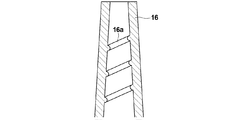
- FIG. 5 is a diagram illustrating an example of a nozzle unit having a structure that generates turbulent flow.
- a spiral inner wall protrusion 16 a is continuously formed on the inner wall of the nozzle portion 16. That is, the presence of the inner wall projection 16 a disturbs the flow of the blood sample as it passes through the nozzle portion 16.
- FIG. 6 is a view showing another example of the nozzle portion having a structure for generating a turbulent flow.
- FIG. 6a is a sectional view passing through the center of the nozzle portion 17, and FIG.
- inner wall projections 17 a, 17 b, 17 c and 17 d are formed on the inner wall of the nozzle portion 17 at a predetermined interval in a spiral shape. That is, the presence of the inner wall projections 17a, 17b, 17c and 17d disturbs the flow of the blood sample when it passes through the nozzle portion 17. Or you may make the inner wall surface of a nozzle part into the ground surface in which many minute unevenness
- regulated by JIS B0601 of JIS specification is 0.1 micrometer or more and 500 micrometers or less, and 1 micrometer or more. More preferably, it is 100 ⁇ m or less, and particularly preferably 5 ⁇ m or more and 50 ⁇ m or less.
- a protruding protrusion 18b may be provided.
- the adapter according to the present embodiment is different from the adapter according to the first embodiment in that the outer wall protrusion is mainly provided on the outer wall surface of the nozzle portion. Therefore, a detailed description of the same configuration as that of the first embodiment is omitted unless particularly necessary.
- FIG. 8 is a schematic diagram showing the configuration of the adapter 31 according to this embodiment
- FIG. 9 is a schematic diagram showing the configuration of the dispensing kit 38 according to this embodiment.
- a in FIG. 8 is a perspective view of the adapter 31
- b in FIG. 8 is a top view of the adapter 31
- c in FIG. 8 is a cross section of the adapter 31 along the line XX in FIG.
- FIG. 9 is a perspective view of the lid 40 of the dispensing container 39
- FIG. 9b is a perspective view of the main body 41 of the dispensing container 39
- 9c is a perspective view of the dispensing kit 38 when the adapter 31 is inserted into the dispensing container 39
- FIG. 9d is a sectional view thereof.
- the adapter 31 and the dispensing kit 38 are preferably used in combination.
- the adapter 31 has a tube structure in which one end is a fitting portion 33 that fits into the distal end portion of the syringe and the other end is a nozzle portion 32, and the outer peripheral surface thereof. A flange 34 and an outer wall projection 36 are provided on the top.
- a carrier 35 that carries a drug mixed in blood is installed in the internal space of the nozzle portion 32.
- the dispensing kit 38 according to the present embodiment includes a dispensing container 39 and an adapter 31, and the dispensing container 39 includes a lid 40 and a main body 41.
- the lid 40 has an opening 40a as an opening for dispensing a sample.
- the opening 40a is formed by a cylindrical protrusion.
- the dispensing container 39 is also used as a centrifuge container.
- the outer wall projection portion 36 is composed of three ribs (straight ribs) that extend straight from the flange portion 34 in the axial direction of the nozzle portion 32 (the direction along the central axis of the nozzle portion 32). It is erected side by side at equal intervals in the direction.
- the outer wall projection 36 has an effective diameter of at least a part on the tip end side of the nozzle part set to a size such that the part is inserted into the opening 40a.
- the effective diameter of the nozzle at a certain position means the overall thickness (outer diameter) of the nozzle, taking into account the size of the outer wall protrusion (that is, considering the presence of the outer wall protrusion), and the nozzle at that position.
- the diameter of the smallest circumscribed circle that includes the projection and the outer wall projection (see FIG. 12 b described later). Due to the presence of the outer wall projection 36 as described above, when the adapter 31 is inserted into the dispensing container 39 as shown in FIG. 9, a gap is formed in the opening 40 a that serves as an air passage (ventilation path V). Thereby, since the pressure rise inside the container accompanying dispensing can be prevented, dispensing work can be performed smoothly. Moreover, the adapter 31 is fixed to the dispensing container 39 by the outer wall protrusion 36 being engaged with the opening 40a of the dispensing container 39, so that the dispensing operation can be performed stably.
- the outer wall protrusion 36 may be formed of the same material as that of the adapter 31 other than the outer wall protrusion, or may be formed of a different material. When formed from the same material, for example, it can be produced by integral molding. In addition, when made of a different material, it is possible to adopt a method of attaching the outer wall projection 36 after producing an adapter without the outer wall projection, for example, a material having higher elasticity than the material of the adapter 31 on the outer wall projection 36. By adopting, the adhesiveness with the dispensing container 39 is increased, and the dispensing operation can be performed more stably.
- the outer wall projection 36 preferably has a tapered shape as shown in FIG. Thereby, when the adapter 31 is inserted into the dispensing container 39, the outer wall projection 36 also functions as an insertion guide, facilitating the insertion operation.
- the outer wall protrusion 36 functions as an insertion stopper for the openings 40a of various sizes by having a tapered shape, it is not limited to a dispensing container having a specific size opening.
- the range of dispensing containers that can be combined with the adapter 31 is expanded. If the diameter of the circle circumscribing the outer wall projection and the size of the opening of the dispensing container are appropriately designed so that they can be fitted, the outer wall projection does not necessarily have a tapered shape. Further, as shown in FIG.
- the outer wall projection 36 changes from a value where the effective diameter of the nozzle portion 32 is larger than the size of the opening 40a toward the tip, so that the adapter 31 can be fitted into the opening 40a. It is preferable to have a stepped portion 36a.
- the blood sample dispensing adapter according to the present embodiment and the dispensing kit including the adapter are provided with the medicine mixed in the blood sample inside the nozzle portion, and thus, similar to the first embodiment.
- the adapter according to the present embodiment includes an outer wall protrusion on the outer wall surface of the nozzle portion that forms an air passage when the nozzle portion is inserted into the opening of the dispensing container. Can be done.
- the rib which comprises an outer wall projection part in this invention is not limited to three straight ribs. That is, the number of ribs may be one, two, or even four or more, and the ribs may extend so as to be twisted with respect to the axial direction of the nozzle portion. However, from the viewpoint of stability when the adapter is inserted, the number of ribs is preferably 3 or more. Further, when there are a plurality of ribs, the plurality of ribs do not necessarily have to be arranged at equal intervals.
- the plate-like rib has been described, but the shape of the rib is not limited to this, and may be, for example, a triangular pyramid shape. Furthermore, the rib does not necessarily have to be connected to the flange portion.
- FIG. 10 is a schematic view showing another modification of the adapter for securing the air passage.
- a in FIG. 10 is a top view and a cross-sectional view of the adapter 42.
- the adapter 42 has an outer wall projection 43 formed of a rib (spiral rib) extending spirally along the circumferential surface in the circumferential direction of the nozzle portion.
- the air passage is formed in a spiral shape between the ribs.
- the spiral rib has a tapered shape.
- the opening and the spiral rib come into contact with each other at an appropriate position, so that the adapter 42 can be fixed to the dispensing container and can be used for dispensing containers having various sizes of openings. Is possible.
- the outer wall projection 43 since the air passage is formed in a spiral shape, there is an advantage that it is possible to prevent the sample from being scattered during dispensing.
- the opening of the dispensing container into which the adapter 42 is inserted may or may not have a structure that is screwed with the spiral rib on the inner wall of the opening (that is, a structure that fits in a screw manner). When the adapter 42 and the dispensing container are screwed in such a manner, in order to improve the passage of air, a notch for vertically cutting the spiral rib may be inserted.
- FIG. 10 b is a top view and a cross-sectional view of the adapter 44.
- the adapter 44 has an outer wall projection 45 composed of three rectangular ribs arranged around the nozzle portion.
- the effective diameter of the tip portion of the nozzle portion (the diameter of the smallest circle circumscribing the outer wall projection 45) is designed to be larger than the inner diameter (opening diameter) of the dispensing container. Therefore, the rib does not advance ahead of the opening, but it is possible to secure a ventilation path. Also in this case, the air passage is formed between the ribs.
- FIG. 10 c is a top view and a cross-sectional view of the adapter 46.
- the adapter 46 has a through hole 47 in the flange portion. Therefore, even if the adapter 46 is inserted until the flange portion comes into contact with the opening of the dispensing container, an air passage can be secured by the through-hole 47. Since the through-hole 47 corresponds to a dispensing container having a small opening, the through-hole 47 is preferably formed on the inner peripheral side of the flange portion.
- FIG. 10 d is a top view and a cross-sectional view of the adapter 48.
- the adapter 48 has a slit-shaped notch 49 that crosses the flange portion except for the tube structure portion. Therefore, even if the adapter 48 is inserted until the flange portion comes into contact with the opening of the dispensing container, the notch 49 can secure the ventilation path.
- the adapter 51 according to the present embodiment is different from the adapter according to the second embodiment mainly in that the distance L between the tip 56a of the outer wall projection 56 and the tip 52a of the nozzle 52 is set within a predetermined range. Different. Therefore, a detailed description of the same configuration as that of the second embodiment will be omitted unless particularly necessary.
- FIG. 11 is a schematic cross-sectional view showing the configuration of the dispensing kit according to the third embodiment
- FIG. 12 is a schematic cross-sectional view showing the configuration of the adapter according to the third embodiment.
- a in FIG. 11 and a in FIG. 12 are cross-sectional views of the adapter according to the present embodiment
- b in FIG. 11 is a cross-sectional view of the dispensing container according to the present embodiment.
- c of FIG. 11 is an expanded sectional view of the front-end
- 12B is an end view of the cut portion viewed from the top when the cross section of the nozzle portion is taken at position A in FIG.
- the adapter 51 has a tube structure in which one end is a fitting portion 53 that fits into the distal end portion of the syringe and the other end is a nozzle portion 52.
- the outer peripheral surface has a flange portion 54 and an outer wall projection 56.
- a carrier (not shown) that carries a drug mixed in blood is installed in the internal space of the nozzle portion 52.
- the dispensing kit according to the present embodiment includes an adapter 51 and a dispensing container 39.
- the dispensing container 39 is the same as the container described in the second embodiment, and has an opening 40a into which the adapter 51 is inserted.
- the outer wall protrusion 56 is composed of three ribs (straight ribs) extending straight from the flange portion 54 in the axial direction of the nozzle portion 52, and the three ribs are arranged in the circumferential direction of the nozzle portion. It is erected side by side at intervals. Further, the outer wall projection part 56 has a step part 56b in which the effective diameter of the nozzle part 52 changes from a value larger than the size of the opening 40a toward the tip to a value at which the adapter 51 can be fitted into the opening 40a. .
- the outer wall projection 56 has a tapered portion that reduces the effective diameter of the nozzle portion 52 toward the tip of the nozzle portion 52, and maintains the effective diameter at the taper end position after the taper portion ends.
- the nozzle portion 52 extends to the vicinity of the tip 52a.
- the effective diameter of the nozzle portion 52 at a certain position is the diameter of the smallest circumscribed circle 57 that includes the nozzle portion 52 and the outer wall projection 56 at that position.
- the length L from the front end 56a of the outer wall projection 56 to the front end 52a of the nozzle portion 52 is defined by the following formula 2. Is set within a predetermined range.
- W represents the inner diameter of the opening (see b in FIG. 11)
- D represents the depth of the opening (see b in FIG. 11)
- ⁇ 1 is the outside of the tip 52a of the nozzle 52. It represents the diameter (see a in FIG. 12).
- ⁇ 2 is because the nozzle part 52 is inclined in the opening 40a due to the difference between the size of the opening 40a (the inner diameter of the opening part) and the effective diameter of the nozzle part 52 in the nozzle part 52 and the outer wall projection part 56.
- the portion R1 is a portion that is inserted into the opening 40a of the nozzle portion 52 and the outer wall projection 56, except for a portion that fits with the opening 40a (a portion where the effective diameter matches the opening diameter). I can say that.
- the effective diameter ⁇ 2 of the nozzle portion of the portion R1 is a constant value when the effective diameter is constant along the axial direction of the nozzle portion, and the effective diameter changes along the axial direction of the nozzle portion.
- the effective diameter is the minimum in the third region R2 on the flange side of the portion R1.
- the one-third region R2 on the flange portion side of the portion R1 is considered because the adapter is fitted in the opening (fitted state). This is because, in the operation of pulling out the nozzle from the opening, the nozzle portion often tilts at the initial stage of the pulling out operation.
- the nozzle part often tilts at the initial stage of pulling out, for example, when the adapter is released from the fitting state, the adapter is shaken to the left or right, or after the fitting state is released, before the adapter is pulled out, This is because the adapter may be shaken to drop the blood remaining at the tip of the tube into the dispensing container.
- the effective diameter of the nozzle portion 52 at the end position A on the tip side of the region R2 in FIG. 12 is ⁇ 2 (see b in FIG. 12).
- FIG. 13 shows dispensing using an adapter (for example, the adapter 31 shown in FIG. 8) in which the distance between the tip of the nozzle portion and the outer wall projection is too long, that is, the distance L is equal to or greater than the depth D of the opening.
- an adapter for example, the adapter 31 shown in FIG. 8
- the distance L is equal to or greater than the depth D of the opening.
- the distance L is greater than or equal to the depth D of the opening, when the adapter 31 is pulled out of the opening, there is no interference with the outer wall protrusion, and the inner wall of the opening and the tip of the nozzle approach each other. (See b in FIG. 13).
- the distance L is preferably less than the depth D of the opening.
- the blood Sa that has circulated around the peripheral surface is attracted in the direction B on the flange side through the gap between the nozzle portion 52b and the outer wall projection 56b due to capillary action, and the surface and outer wall of the adapter.
- blood Sa adheres to the surface of the adapter or the protrusion on the outer wall when the adapter is pulled out of the dispensing container, it adheres to the surface of the dispensing container such as the inner wall or the upper surface of the opening, and blood Sa is surrounded by the dispensing operation. May be scattered. Therefore, the distal end 56a of the outer wall projection 56 is separated from the distal end of the nozzle part to such an extent that it does not come into contact with the blood Sa that has come around the peripheral surface of the distal end of the nozzle part as described above.
- FIG. 15 is a schematic sectional view showing a dispensing process using the adapter 51 according to the present embodiment.
- the gap ⁇ maximum gap
- the gap ⁇ for the nozzle portion 52 to tilt in the opening 40a is slightly pulled out of the opening 40a from the state where the adapter 51 is fitted in the opening 40a (see a in FIG. 15). Occurs when the lever is released (see b in FIG. 15).
- FIG. 15d is a cross-sectional end view taken along line YY of FIG. 15b. As can be seen from FIG. 15 d, the gap ⁇ in the state of FIG.
- FIG. 15 b is substantially equal to the size of the opening 40 a (the inner diameter of the opening) minus the effective diameter of the nozzle portion 52.
- This gap ⁇ becomes a so-called “play” of the nozzle portion 52 in the opening 40a, and the nozzle portion 52 can be tilted in the opening 40a (see c in FIG. 15).
- FIG. 16 is a schematic diagram showing a state where the modeled nozzle portion 52 is inserted into the opening of the dispensing container 39.
- the effective diameter of the nozzle portion 52 is approximated to be constant in the vicinity of the opening 40a, and the nozzle portion 52 is modeled as a cylinder 58 having a diameter ⁇ 2. From this schematic diagram, the relationship represented by the following formula 3 is obtained for W, D, ⁇ 2 and ⁇ .
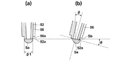
- the nozzle part 52 when the nozzle part 52 is inclined at an angle ⁇ as shown in FIG. 17B from the state where the central axis of the nozzle part 52 is along the vertical direction as shown in FIG. 17A, the nozzle part 52 remains at the tip 52a of the nozzle part 52.
- the blood Sa wraps around in the axial direction on the peripheral surface of the nozzle portion 52 by ( ⁇ 1 / 2) ⁇ tan ⁇ . If the above equation 4 is applied to tan ⁇ of this equation, the lower limit of the above equation 2 is obtained.
- the inner diameter W of the opening of a general dispensing container is 6 mm, and the depth D is 2.5 mm.
- the outer diameter ⁇ 1 at the tip of the nozzle portion is 2.4 mm
- the effective diameter ⁇ 2 of the nozzle portion in the portion forming the gap is 5.2 m.
- the nozzle portion is inclined by approximately 18 degrees, and the distance L between the tip of the outer wall projection and the tip of the nozzle portion is set in a range of 0.8 or more and less than 2.5 mm.
- the blood sample dispensing adapter according to the present embodiment and the dispensing kit including the adapter are provided with the medicine mixed in the blood sample inside the nozzle portion, and thus, similar to the first embodiment.
- the adapter according to the present embodiment includes an outer wall protrusion on the outer wall surface of the nozzle portion that forms an air passage when the nozzle portion is inserted into the opening of the dispensing container, The same effect is produced.
- the distance between the tip of the outer wall projection and the tip of the nozzle is set within the predetermined range, so the blood remaining at the tip of the nozzle and the dispensing container Can be reduced.
- the outer wall protrusion is a straight rib.
- the outer wall protrusion may be a spiral rib. That is, the distance between the tip of the spiral rib and the tip of the nozzle portion is set in the predetermined range.
- the medicine is carried on the carrier has been described, but it goes without saying that the medicine may also be applied to the inner wall of the nozzle portion 52 in this embodiment.
- the rib which comprises an outer wall projection part in this invention is not limited to three straight ribs, About the rib, it is the same as that of description in 2nd Embodiment.
- the adapter 61 according to the present embodiment is different from the adapter according to the third embodiment in that the tip 62a of the nozzle portion 62 can be fitted to the needle base 69b of the needle 69 attached to the syringe. Therefore, a detailed description of the same configuration as that of the third embodiment is omitted unless particularly necessary.
- FIG. 18 is a schematic cross-sectional view showing the configuration of the needle kit according to the fourth embodiment. Specifically, a in FIG. 18 represents a state in which the syringe 67 and the needle 69 are fitted, and b in FIG. 18 represents a state in which the syringe 67 and the adapter 61 are fitted. FIG. 18 c shows a state where the syringe 67 and the adapter 61 are fitted, and the needle 69 is fitted to the tip 62 a of the nozzle portion 62 of the adapter 61.
- the needle kit according to the present embodiment includes an adapter 61, a syringe 67, and a needle 69, as shown in FIG.
- the needle kit may include an adapter 61 and a needle 69.
- the syringe 67 is not particularly limited, but is the same as, for example, the syringe of FIG.
- the needle 69 includes a needle body 69a (needle tube) and a needle base 69b that holds the needle body 69a.
- the material and size of the needle body 69a are not particularly limited.
- the material of the needle body 69a is a stainless alloy, and the diameter of the tube is 0.4 to 1.2 mm.
- the material of the needle base 69 b is, for example, a resin such as PE, PP, and PS, and the needle base 69 b has an opening that can be fitted to the distal end portion 67 a of the syringe 67.
- the needle 69 is used by fitting the fitting portion of the needle base 69b and the tip portion 67a of the syringe 67 (see FIG. 18a). After blood collection is completed, the needle 69 is removed from the syringe 67.
- the adapter 61 is the same as the adapter 51 according to the third embodiment (see a in FIG. 11), for example, but the outer diameter ⁇ 3 of the tip 62a of the nozzle portion 62 is fitted to the fitting portion of the needle base 69b. It differs in that it is a possible size. That is, the outer diameter ⁇ 3 (excluding the outer wall projection 66) of the tip 62a of the nozzle portion 62 matches the inner diameter ⁇ 4 of the fitting portion of the needle base 69b.
- the outer diameter ⁇ 3 of the tip 62a of the nozzle 62, the inner diameter ⁇ 4 of the fitting portion of the needle base 69b, the inner diameter of the fitting portion 63, and the outer diameter of the tip portion 67a of the syringe 67 are fitted together. Match as much as possible.
- the adapter 61 is used by fitting the fitting portion 63 of the adapter 61 and the distal end portion 67a of the syringe 67 when dispensing the collected blood after blood collection is finished and the needle 69 is removed from the syringe 67. (See b in FIG. 18).
- the needle 69 is removed from the syringe 67 and discarded as it is.
- the adapter 61 and the syringe 67 are discarded as they are fitted.
- the needle kit according to the present embodiment the needle 69, the adapter 61, and the syringe 67 are fitted by fitting the needle 69 and the adapter 61 and fitting the adapter 61 and the syringe 67 as shown in FIG. 67 can be discarded as a unit.
- the opening of the nozzle part 62 of the adapter 61 and the opening of the needle base 69b can be closed, the scattering of blood can be prevented more than before.
- Dispensing container 40 Dispensing container lid 40 a Lid opening S Blood Sa Blood remaining at the tip of the nozzle
Landscapes
- Health & Medical Sciences (AREA)
- Life Sciences & Earth Sciences (AREA)
- Engineering & Computer Science (AREA)
- Animal Behavior & Ethology (AREA)
- Public Health (AREA)
- Pathology (AREA)
- Physics & Mathematics (AREA)
- Biomedical Technology (AREA)
- Heart & Thoracic Surgery (AREA)
- Medical Informatics (AREA)
- Molecular Biology (AREA)
- Surgery (AREA)
- Hematology (AREA)
- General Health & Medical Sciences (AREA)
- Biophysics (AREA)
- Veterinary Medicine (AREA)
- Clinical Laboratory Science (AREA)
- Chemical & Material Sciences (AREA)
- Chemical Kinetics & Catalysis (AREA)
- Manufacturing & Machinery (AREA)
- Medical Preparation Storing Or Oral Administration Devices (AREA)
- Sampling And Sample Adjustment (AREA)
- Infusion, Injection, And Reservoir Apparatuses (AREA)
- Measurement Of The Respiration, Hearing Ability, Form, And Blood Characteristics Of Living Organisms (AREA)
Abstract
検査試料の作製において、血液の空気への接触を抑制しながら、血液試料に混入する薬剤の有無或いはその種類を分注の際に変更することを可能とする血液試料分注用アダプタ並びにそれを備えた分注キット及び針キットを提供する。シリンジの先端部に装着される管構造の血液試料分注用アダプタ1であって、一端に先端部に嵌合する嵌合部3を、他端にノズル部2を、外周面上にフランジ部4を有し、ノズル部2の内側に、血液試料Sに混入される薬剤5を備えるアダプタ1を使用して分注する。
Description
本発明は、血液等の液体物質を分注する際にシリンジに装着するアダプタ及びそれを備えた分注キットに関するものである。
患者(人及びその他の動物を含む)から採取された血液は、スピッツ等の容器に分注された後、遠心分離等の処理にかけられる。そして、この際、血液の凝固を防止するため、血液に抗凝固剤が混合されることがある。
抗凝固剤の混合方法としては、例えば、(1)予め抗凝固剤が封入された真空採血管を使用して採血し、その後転倒混和する方法(特許文献1)、(2)抗凝固剤が内壁に塗布されたシリンジで採血し、その後転倒混和する方法(特許文献2)、及び(3)採血後に抗凝固剤が封入された検査容器(例えば、ベクトン・ディッキンソン・アンド・カンパニー社製のマイクロティナ(登録商標)微量採血管)へ分注し、その後転倒混和する方法がある。
しかしながら、上記(1)の方法では、乳幼児や小動物から採血する場合、真空採血管の規定採取量ほど採血できない場合がある。また、(2)の方法では、採取した血液のすべてと抗凝固剤が混合されてしまい、このような試料は他の検査で使用できない場合もある。この場合、他のシリンジを使用して再度採血が必要となるが、これは作業として効率が悪く、また採血の回数(特に針を刺す回数)を増やすことは患者(特に動物)への負担を増やしてしまうため好ましくない。
また、上記(3)の方法では、血液をシリンジから検査容器に分注する際に血液が空気に触れてしまうため、凝固が発生しやすく、素早く分注しかつ分注後素早く転倒混和しなければならないという作業上の制約が生じてしまう。このとき、例えば分注作業に慣れていない者が分注を行うような場合に、効果的に凝固を防止することができないことも起こり得る。
本発明は上記問題に鑑みてなされたものであり、血液試料の空気への接触を抑制しながら、血液試料に混入する薬剤の有無或いはその種類を分注の際に変更することを可能とする血液試料分注用のアダプタ並びにそれを備えた分注キット及び針キットを提供することを目的とするものである。
上記課題を解決するために、血液試料分注用のアダプタは、
シリンジの先端部に装着される管構造のアダプタであって、
一端にシリンジの先端部に嵌合する嵌合部を、他端にノズル部を、外周面上にフランジ部を有し、
ノズル部の内側に、血液試料に混入される薬剤を備えるものである。
シリンジの先端部に装着される管構造のアダプタであって、
一端にシリンジの先端部に嵌合する嵌合部を、他端にノズル部を、外周面上にフランジ部を有し、
ノズル部の内側に、血液試料に混入される薬剤を備えるものである。
そして、本発明のアダプタにおいて、ノズル部の内壁面はすり面であることが好ましく、またノズル部の内壁面上に螺旋状に形成された内壁突起部を有することが好ましい。
また、本発明のアダプタにおいて、薬剤がノズル部の内壁に塗布された構成或いは薬剤が担持体に担持された構成を採用することができる。
また、本発明のアダプタにおいて、ノズル部の外壁面上には外壁突起部が立設されており、血液試料が分注される分注容器に形成された開口部にノズル部が挿入された際、外壁突起部と分注容器が接触することによりフランジ部と開口部の間に隙間を生じることが好ましい。この場合において、ノズル部及び外壁突起部の最小外接円の直径であるノズル部の実効径であってノズル部の先端部分の実効径は、当該先端部分が開口部に挿入される大きさであることが好ましい。また、外壁突起部は先細りのテーパ形状を有することが好ましい。
外壁突起部については、ノズル部の軸方向に伸びている構成を採用できる。この場合、外壁突起部は、ノズル部の実効径が先端に向かって開口部の内径よりも大きい値から開口部に嵌合可能な値へ変化する段差部を有することが好ましい。また、外壁突起部は、3個以上あり、ノズル部の周方向に並んで配置されていることが好ましい。
或いは外壁突起部については、ノズル部の周面に沿って螺旋状に伸びている構成を採用できる。
また、本発明のアダプタにおいて、開口部の内径をW、開口部の深さをD、ノズル部の先端の外径をφ1、及び、ノズル部及び外壁突起部の部分のうち、開口部の内径とノズル部の実効径との差により開口部内でノズル部が傾くための間隙を開口部との間に形成する部分のノズル部の実効径をφ2としたとき、外壁突起部の先端からノズル部の先端までの長さLが、下記式1を満たすことが好ましい。

また、本発明のアダプタが外壁突起部を備える場合に、ノズル部の先端部分の実効径が開口部の内径よりも大きい構成を採用することもできる。
また、本発明のアダプタにおいて、フランジ部は貫通口または切欠きを有していてもよい。
また、本発明のアダプタにおいて、ノズル部の長さは3mm以上30mm以下であることが好ましく、フランジ部の外径は8mm以上30mm以下であることが好ましい。
また、本発明のアダプタにおいて、ノズル部の内部空間の体積が10μL以上1mL以下であることが好ましい。
また、本発明のアダプタにおいて、薬剤の種類に対応した特定の色を有することが好ましい。
本発明の分注キットは、外壁突起部を備える上記に記載のアダプタと、外壁突起部と嵌合する開口部を有する分注容器とを備えるものである。
さらに本発明の針キットは、上記に記載のアダプタと、シリンジの先端部に嵌合する針基を有する針とを備え、アダプタのノズル部も針基に嵌合可能であるものである。そして、本発明の針キットは、アダプタの嵌合部と嵌合する先端部を有するシリンジを備えてもよい。
本発明の血液試料分注用アダプタ並びにそれを備えた分注キット及び針キットは、ノズル部の内側に、血液試料に混入される薬剤を備えるから、薬剤の混入が必要な場合にのみシリンジに装着し分注するだけで、薬剤の混入が可能となる。この結果、アダプタの着脱によって、血液試料の空気への接触を抑制しながら、血液試料に混入する薬剤の有無或いはその種類を分注の際に変更することが可能となる。
以下、本発明の実施形態について図面を用いて説明するが、本発明はこれに限られるものではない。なお、視認しやすくするため、図面中の各構成要素の縮尺等は実際のものとは適宜異ならせてある。
なお、以下の実施形態では、説明を分かりやすくするために採血及び血液検査の際に使用するシリンジ及び当該シリンジに対応したアダプタ及び分注容器について説明する。
「第1の実施形態」
まず、アダプタの第1の実施形態について説明する。図1は、本実施形態に係るアダプタの構成を示す概略図である。具体的には、図1のaはアダプタの上面図であり、図1のbは図1aのX-X線における断面図であり、図1のcは底面図である。図2は、シリンジに装着された状態のアダプタを示す概略断面図である。図3は、アダプタを使用して分注する様子を示す概略断面図である。
まず、アダプタの第1の実施形態について説明する。図1は、本実施形態に係るアダプタの構成を示す概略図である。具体的には、図1のaはアダプタの上面図であり、図1のbは図1aのX-X線における断面図であり、図1のcは底面図である。図2は、シリンジに装着された状態のアダプタを示す概略断面図である。図3は、アダプタを使用して分注する様子を示す概略断面図である。
本実施形態に係る血液試料分注用のアダプタ1は、図1及び2に示すように、一端がシリンジ7(つまりシリンジ本体20)の先端部20aに嵌合する嵌合部3であり、他端がノズル部2である管構造を有し、その管構造の外周面上にフランジ部4を有する。そして、本実施形態に係るアダプタ1では、ノズル部2の内部である内壁に血液に混入するヘパリン等の抗凝固剤5(薬剤)が塗布されている。
また、本実施形態に係るシリンジキットは、本実施形態に係るアダプタと、例えば図2に示すようなシリンジ本体20及びプランジャ21からなるシリンジ7とから構成される。なお、シリンジは、先端部22aの周囲に針ロック部22bを有するシリンジ本体22、及びプランジャ23から構成されるシリンジ8でもよい。
ノズル部2は、管構造のうち、アダプタ1がシリンジ7に装着された際にシリンジ7の先端部20aが到達しない部分である。ノズル部2の内壁面には抗凝固剤5が塗布されており、当該ノズル部2からシリンジ7中の血液Sが流出する際に、血液Sと抗凝固剤5が接触して抗凝固剤5が血液S中に混入することとなる。ノズル部2の先端2aの外径は嵌合部3の内径(各地点の内径のうち最小のもの)より小さいことが好ましい。嵌合部3の内径はシリンジ7の先端部20aの外径を反映しており、ノズル部2の先端2aの外径が嵌合部3の内径より小さければ、ノズル部2の先端2aの外径が先端部20aの外径より小さくなるためである。これにより、ノズル部2の容器への挿入作業がやり易くなる。またノズル部2の先端2aの内径は、ノズル部通過時の溶血を防止するため0.5mm以上であることが好ましい。ノズル部2は、先端に向かって先細りとなるテーパ形状であることが好ましい。
特にノズル部2の長さは3mm以上30mm以下であることが特に好ましい。3mm以上であると血液Sと抗凝固剤5とのノズル部通過時の混和状態が(例えば、抗凝固剤5の混入量及び混和の均一性の観点で)十分となり、30mmより小さければ分注時の取り扱いが容易になるためである。この長さは、市販のピペット用ディスポチップと同程度の長さである。また微量の血液を無駄にしない観点から、ノズル部2の内部空間の体積は10μL以上であることが好ましく、抗凝固剤との混和を十分とするために1mL以下であることが好ましい。
嵌合部3は、管構造のうち、シリンジ7の先端部20aと嵌合する部分であり、その形状、内径及び長さは、装着対象の先端部20aの形状、大きさ及び長さに適合するように設計される。例えば、嵌合部3は、JIS規格のJIS T-3210等のシリンジに適合するように設計される。嵌合部3の端部3aから先端部20aが挿入されることにより、アダプタ1がシリンジ7に装着される(図2のaを参照)。本実施形態では、図2のaに示されるように、嵌合部3と先端部20aは単に嵌め合わさる構造を有するが、例えばネジ構造を有してもよいし、凸部と凹部(窪んだ部分や切り欠き部分)で係合する構造を有してもよい。
フランジ部4は、手でアダプタ1をシリンジ7に装着する際に、血液Sが手に付着することを防止する機能、及び図3に示されるように容器30の開口部に接触しアダプタ1の姿勢を容器30に対して固定する機能を有する。フランジ部4の外径は8mm以上30mm以下であることが好ましい。フランジ部4の外形が8mm以上であれば、血液Sが手に付着する懸念が減り、容器30に対する固定が安定する一方、30mm以下であれば、アダプタ1の取り扱いが容易となるためである。また、フランジ部4は、直線状の外周部または切り欠き部などを含む転がり防止部4aを有することが好ましい。これにより、アダプタ1を卓上に置いた場合の転がりを防止することができる。本実施形態では、フランジ部4は、管構造の全周に形成されているが、必ずしも全周である必要はない。管構造の中心に沿った方向において、フランジ部4を形成する位置は、特に限定されないが、アダプタ1の着脱のし易さの観点から、ノズル部2と嵌合部3とが接続する位置或いはその近傍であることが好ましい。また図2のbに示されるように、針ロック部22bを有するシリンジ8の先端部22aにアダプタ1が装着される場合には、フランジ部4は予め針ロック部22bと干渉しないように設計される。
アダプタ1の材料は、PE(ポリエチレン)、PP(ポリプロピレン)及びPS(ポリスチレン)等の樹脂が好ましい。また、アダプタ1は、例えば上記のような樹脂を用いた一体成型によって製造される。
本発明のアダプタを利用した検査は例えば以下のように実施される。まず、シリンジを用いた採血後、抗凝固剤を混入しない検査試料を作製する場合には、アダプタを装着せず、そのままシリンジ内の血液を検査容器に分注する。そして、抗凝固剤を混入しない検査試料を必要な数だけ作製した後に、抗凝固剤を混入する検査試料の作製に移る。抗凝固剤を混入する検査試料を作製する場合には、アダプタをシリンジに装着し、スピッツ等の検査容器に血液を分注する。そして、抗凝固剤を混入する検査試料の作製がすべて終了したら、シリンジとアダプタをそのまま廃棄する。上記のように、抗凝固剤を混入しない検査試料の作製の後に、アダプタをシリンジに装着することで、血液の空気への接触を抑制しながら容易に抗凝固剤が混入された検査試料を作製することができる。なお、一般的な血液試料(例えば、すべての検査結果に影響を与えない薬剤が予め血液中に混入されたもの)を検査する場合も同様である。
以上のように、本実施形態に係る血液試料分注用アダプタは、ノズル部の内側に、血液に混入される抗凝固剤を備えるから、抗凝固剤の混入が必要な場合にのみアダプタをシリンジに装着し分注するだけで、抗凝固剤の混入が可能となる。この結果、アダプタの着脱によって、血液の空気への接触を抑制しながら、血液に混入する抗凝固剤の有無を分注の際に変更することが可能となる。
<第1の実施形態に係る変形例>
本発明において、「薬剤」とは、血液に混合される化合物をいう。したがって第1の実施形態では、薬剤が抗凝固剤である場合について説明したが、本発明において薬剤は、これに限られず、凝固促進剤や分離剤(血清分離剤及び血漿分離剤を含む)でもよい。例えば、薬剤としては抗凝固剤としてのEDTA(エチレンジアミン四酢酸)、ヘパリンナトリウム、ヘパリンリチウム、クエン酸ナトリウム、クエン酸三ナトリウム、フッ化物及びシュウ酸カリウムの少なくとも1種、または、凝固促進剤としてのシリカ、トロンビン及び珪藻土の少なくとも1種を使用することができる。また、分離剤としては、例えばポリエステルゲルが挙げられる。
本発明において、「薬剤」とは、血液に混合される化合物をいう。したがって第1の実施形態では、薬剤が抗凝固剤である場合について説明したが、本発明において薬剤は、これに限られず、凝固促進剤や分離剤(血清分離剤及び血漿分離剤を含む)でもよい。例えば、薬剤としては抗凝固剤としてのEDTA(エチレンジアミン四酢酸)、ヘパリンナトリウム、ヘパリンリチウム、クエン酸ナトリウム、クエン酸三ナトリウム、フッ化物及びシュウ酸カリウムの少なくとも1種、または、凝固促進剤としてのシリカ、トロンビン及び珪藻土の少なくとも1種を使用することができる。また、分離剤としては、例えばポリエステルゲルが挙げられる。
また、第1の実施形態では、薬剤の有無を変更した場合について説明したが、薬剤の種類を変更するために本発明のアダプタを使用してもよい。例えば、アダプタ無しで最初に分注した後、種類Aの薬剤が塗布されたアダプタを使用して分注し、その後種類Bの薬剤が塗布されたアダプタに交換し分注する等の分注方法が考えられる。さらに、上記のように種類の異なる薬剤をアダプタに塗布する場合には、アダプタの色をその種類に対応した特定の色にすれば、薬剤の種類を目視で識別することが容易となり間違いを防止することができる。配色は、例えばJIS規格のJIS T3233のカラーコードに従う。色を付す場所は、アダプタの全体でもよいし、一部分(例えばフランジ部や後述する外壁突起部)のみでもよい。
また、第1の実施形態では、薬剤がノズル部の内壁に塗布された場合について説明したが、本発明はこれに限られない。すなわち本発明において、「ノズル部の内側に」薬剤を備えるとは、ノズル部の内壁のみに薬剤が塗布された場合のみならず、ノズル部の内部空間に薬剤を保持する場合も含む意味である。例えば、図4に示されるように、薬剤を担持する担持体15(例えば、薬剤を吸着可能な綿または不織布からなるシート)をノズル部11の内部に設置してもよい。担持体15は、他の固定部材によってノズル部11の内部に固定してもよいが、ノズル部11の形状によっては必ずしも固定する必要はない。例えば、ノズル部11の先端11aの内径が担持体15の幅より小さければ、通常、分注の際に担持体15がノズル部11から出てくることはない。
また、本発明のアダプタにおいて、薬剤の混合を促進させるために、ノズル部の内壁に乱流を生じさせる構造を形成してもよい。例えば、図5は、乱流を生じさせる構造を有するノズル部の一例を示す図である。具体的には、図5では、ノズル部16の内壁に螺旋状の内壁突起部16aが連続的に形成されている。つまり、この内壁突起部16aの存在により、血液試料がノズル部16を通過する際にその流れが乱される。また、図6は、乱流を生じさせる構造を有するノズル部の他の一例を示す図であり、図6のaはノズル部17の中心を通る断面図であり、図6のbはY-Y線の断面図である。具体的には、図6では、ノズル部17の内壁に内壁突起部17a、17b、17c及び17dが螺旋状に所定の間隔を置いて形成されている。つまり、この内壁突起部17a、17b、17c及び17dの存在により、血液試料がノズル部17を通過する際にその流れが乱される。あるいは、ノズル部の内壁面を、微小な凹凸が多数形成されたすり面にしてもよい。この場合には、その微小な凹凸の存在により、血液試料がノズル部を通過する際にその流れが乱される。なお、内壁面のすり面の上記凹凸による粗さについては、JIS規格のJIS B0601で規定される方法によって測定された十点平均粗さが0.1μm以上500μm以下であることが好ましく、1μm以上100μm以下であることがさらに好ましく、5μm以上50μm以下であることが特に好ましい。内壁面の微小な凸凹をこの範囲内の形状とすることによって、血液試料と薬剤の混合が好適に促進される。
また、本発明のアダプタにおいて、ノズル部が下向きの状態になったときに薬剤の垂れにくさを確保するために、図7に示されるように、ノズル部18の端部18aに中心に向かって突出した突起部18bを設けてもよい。
「第2の実施形態」
次に、アダプタの第2の実施形態について説明する。本実施形態に係るアダプタは、主にノズル部の外壁面上に外壁突起部を有する点で、第1の実施形態に係るアダプタと異なる。したがって、第1の実施形態と同様の構成についての詳細な説明は、特に必要がない限り省略する。
次に、アダプタの第2の実施形態について説明する。本実施形態に係るアダプタは、主にノズル部の外壁面上に外壁突起部を有する点で、第1の実施形態に係るアダプタと異なる。したがって、第1の実施形態と同様の構成についての詳細な説明は、特に必要がない限り省略する。
図8は本実施形態に係るアダプタ31の構成を示す概略図であり、図9は本実施形態に係る分注キット38の構成を示す概略図である。具体的には、図8のaはアダプタ31の斜視図であり、図8のbはアダプタ31の上面図であり、図8のcは図8のbのX-X線におけるアダプタ31の断面図である。また、図9のaは分注容器39の蓋40の斜視図であり、図9のbは分注容器39の本体41の斜視図である。さらに、図9のcは分注容器39にアダプタ31が挿入されたときの分注キット38の斜視図であり、図9のdはその断面図である。このようにアダプタ31と分注キット38は好適には組み合わせて使用される。
本実施形態に係るアダプタ31は、図8に示すように、一端がシリンジの先端部に嵌合する嵌合部33であり、他端がノズル部32である管構造を有し、その外周面上にフランジ部34と外壁突起部36を有する。そして、本実施形態に係るアダプタ31では、血液に混入する薬剤を担持する担持体35がノズル部32の内部空間に設置されている。また、本実施形態に係る分注キット38は、分注容器39及びアダプタ31から構成され、分注容器39は、蓋40及び本体41から構成される。蓋40は試料を分注するための開口部として開口40aを有する。例えばこの開口40aは円筒状の突起によって形成される。例えば分注容器39は、遠心分離容器としても使用される。
外壁突起部36は、フランジ部34からノズル部32の軸方向(ノズル部32の中心軸に沿った方向)に真っ直ぐ伸びる3つのリブ(ストレートリブ)から構成され、3つのリブはノズル部の周方向に等間隔に並んで立設されている。そして、外壁突起部36は、少なくともノズル部の先端側の少なくとも一部分の実効径が、当該部分が開口40aに挿入される大きさに設定されている。ある位置におけるノズル部の実効径とは、外壁突起部の大きさも踏まえた(つまり外壁突起部の存在を考慮した)ノズル部の総合的な太さ(外径)を意味し、その位置におけるノズル部及び外壁突起部を内包する最小の外接円の直径とする(後述する図12のbを参照)。このような外壁突起部36が存在することにより、図9のように分注容器39にアダプタ31が挿入されたとき、開口40aに空気の通り道(通気路V)となる隙間が形成される。これにより、分注に伴う容器内部の圧力上昇を防止できるため、分注作業を円滑に行うことができる。また、外壁突起部36が分注容器39の開口40aと嵌合することで、アダプタ31が分注容器39に固定され、分注作業を安定して行うことができる。外壁突起部36は、アダプタ31の外壁突起部以外の部分と同じ材料で形成されてもよいし、異なる材料で形成されてもよい。同じ材料で形成される場合には、例えば一体成型で作製可能である。また、異なる材料で作成される場合には、外壁突起部のないアダプタを作製した後に、外壁突起部36を取り付ける方法を採用でき、例えば外壁突起部36にアダプタ31の材料よりも弾性の高い材料を採用することで分注容器39との密着性が高まり、より分注作業を安定して行うことができる。
外壁突起部36は、図8に示すように先細りのテーパ形状を有することが好ましい。これにより、アダプタ31の分注容器39への挿入の際に外壁突起部36が挿入ガイドとしても機能し、挿入作業がし易くなる。また、テーパ形状を有することにより、分注容器39の様々な大きさの開口40aに対して外壁突起部36が挿入ストッパとして機能するため、特定の大きさの開口を有する分注容器に限らず、アダプタ31と組合せが可能な分注容器の範囲が広がる。なお、外壁突起部に外接する円の直径と分注容器の開口の大きさとが嵌合可能に適切に設計されていれば、外壁突起部は必ずしもテーパ形状を有していなくてもよい。さらに外壁突起部36は、図8に示すように、ノズル部32の実効径が先端に向かって上記開口40aの大きさよりも大きい値から、アダプタ31が上記開口40aに嵌合可能な値へ変化する段差部36aを有することが好ましい。上記のような段差部36aを有することにより、段差部36aに嵌合する特定の大きさの開口を有する分注容器39については、アダプタ31を挿入し固定した際の安定性が向上する。
以上のように、本実施形態に係る血液試料分注用アダプタ及びそれを備えた分注キットは、ノズル部の内側に、血液試料に混入される薬剤を備えるから、第1の実施形態と同様の効果を奏する。また、本実施形態に係るアダプタは、ノズル部の外壁面上に、ノズル部が分注容器の開口に挿入された際に通気路を形成する外壁突起部を備えるから、分注作業を円滑に行うことが可能となる。
<第2の実施形態に係る変形例>
第2の実施形態では、薬剤が担持体に担持されている場合について説明したが、本実施形態においても薬剤は、ノズル部32の内壁に塗布されていてもよいことは言うまでもない。また、本発明において外壁突起部を構成するリブは、3つのストレートリブに限定されない。つまり、リブの個数は1個でも2個でも、さらには4個以上でもよく、リブはノズル部の軸方向に対してねじれるように伸びていてもよい。ただし、アダプタを挿入した際の安定性の観点から、リブの個数は3個以上であることが好ましい。また、リブが複数ある場合に、複数のリブは必ずしも等間隔に並んでいる必要もない。また、本実施形態では板状のリブについて説明したが、リブの形状は、これに限定されず、例えば三角錐形状でもよい。さらに、リブは必ずしもフランジ部に接続している必要もない。
第2の実施形態では、薬剤が担持体に担持されている場合について説明したが、本実施形態においても薬剤は、ノズル部32の内壁に塗布されていてもよいことは言うまでもない。また、本発明において外壁突起部を構成するリブは、3つのストレートリブに限定されない。つまり、リブの個数は1個でも2個でも、さらには4個以上でもよく、リブはノズル部の軸方向に対してねじれるように伸びていてもよい。ただし、アダプタを挿入した際の安定性の観点から、リブの個数は3個以上であることが好ましい。また、リブが複数ある場合に、複数のリブは必ずしも等間隔に並んでいる必要もない。また、本実施形態では板状のリブについて説明したが、リブの形状は、これに限定されず、例えば三角錐形状でもよい。さらに、リブは必ずしもフランジ部に接続している必要もない。
さらに、図10は、通気路を確保するためのアダプタの他の変形例を示す概略図である。具体的には図10のaは、アダプタ42の上面図と断面図である。アダプタ42は、ノズル部の周方向に周面に沿って螺旋状に伸びるリブ(スパイラルリブ)からなる外壁突起部43を有する。この場合、通気路はリブとリブの間に螺旋状に形成される。また、このスパイラルリブは先細りのテーパ形状を有する。これにより、アダプタ42を分注容器に挿入したときに適当な位置で開口とスパイラルリブが接触し、アダプタ42を分注容器に固定可能となり、様々な大きさの開口を有する分注容器に対応可能である。さらに、外壁突起部43の場合には、通気路が螺旋状に形成されているため、分注の際に試料が飛散することを防止できるという利点もある。アダプタ42が挿入される分注容器の開口は、開口の内壁に上記スパイラルリブと螺合する構造(つまりネジ式に嵌合する構造)を有していても、有していなくてもよい。アダプタ42と分注容器がそのように螺合する場合には、空気の通りを良くするため、スパイラルリブを縦断する切り込みを入れてもよい。
また、図10のbは、アダプタ44の上面図と断面図である。アダプタ44は、ノズル部の周囲に並べられた3個の矩形状のリブからなる外壁突起部45を有する。外壁突起部45の場合には、ノズル部の先端部分の実効径(外壁突起部45に外接する最小の円の直径)が分注容器の開口部の内径(開口の直径)よりも大きく設計されているため、リブは開口より先に進行しないが、通気路を確保することは可能である。この場合も、通気路はリブとリブの間に形成される。
また、図10のcは、アダプタ46の上面図と断面図である。アダプタ46は、フランジ部に貫通口47を有する。したがって、フランジ部が分注容器の開口部に接触するまでアダプタ46が挿入されても、この貫通口47によって通気路を確保することができる。貫通口47は、開口の小さい分注容器に対応するため、フランジ部の内周側に形成されることが好ましい。
また、図10のdは、アダプタ48の上面図と断面図である。アダプタ48は、管構造部分を除きフランジ部を横断するスリット状の切欠き49を有する。したがって、フランジ部が分注容器の開口部に接触するまでアダプタ48が挿入されても、この切欠き49によって通気路を確保することができる。
「第3の実施形態」
次に、アダプタの第3の実施形態について説明する。本実施形態に係るアダプタ51は、主に外壁突起部56の先端56aとノズル部52の先端52aとの距離Lが所定範囲内に設定されている点で、第2の実施形態に係るアダプタと異なる。したがって、第2の実施形態と同様の構成についての詳細な説明は、特に必要がない限り省略する。
次に、アダプタの第3の実施形態について説明する。本実施形態に係るアダプタ51は、主に外壁突起部56の先端56aとノズル部52の先端52aとの距離Lが所定範囲内に設定されている点で、第2の実施形態に係るアダプタと異なる。したがって、第2の実施形態と同様の構成についての詳細な説明は、特に必要がない限り省略する。
図11は、第3の実施形態に係る分注キットの構成を示す概略断面図であり、図12は、第3の実施形態に係るアダプタの構成を示す概略断面図である。具体的には、図11のa及び図12のaは、本実施形態に係るアダプタの断面図であり、図11のbは、本実施形態に係る分注容器の断面図である。そして、図11のcは、本実施形態に係るアダプタの先端部分の拡大断面図である。また、図12のbは、図12のaにおける位置Aでノズル部の断面を取ったときの上面から見た切断部端面図である。
本実施形態に係るアダプタ51は、図11及び図12に示されるように、一端がシリンジの先端部に嵌合する嵌合部53であり、他端がノズル部52である管構造を有し、その外周面上にフランジ部54と外壁突起部56を有する。そして、本実施形態においても、血液に混入する薬剤を担持する担持体(図示省略)がノズル部52の内部空間に設置されている。また、本実施形態に係る分注キットは、アダプタ51及び分注容器39から構成される。分注容器39は、第2の実施形態で説明した容器と同じであり、アダプタ51が挿入される開口40aを有する。
外壁突起部56は、第2の実施形態と同様に、フランジ部54からノズル部52の軸方向に真っ直ぐ伸びる3つのリブ(ストレートリブ)から構成され、3つのリブはノズル部の周方向に等間隔に並んで立設されている。また、外壁突起部56は、ノズル部52の実効径が先端に向かって上記開口40aの大きさよりも大きい値から、アダプタ51が上記開口40aに嵌合可能な値へ変化する段差部56bを有する。さらに、外壁突起部56は、ノズル部52の先端に向かってノズル部52の実効径が小さくなるようなテーパ部分を有し、テーパ部分が終わった位置以降もテーパ終了位置での実効径を維持しながらノズル部52の先端52aの近傍にまで伸びている。なお、ある位置におけるノズル部52の実効径は、前述したように、その位置におけるノズル部52及び外壁突起部56を内包する最小の外接円57の直径である。
外壁突起部56の先端56aからノズル部52の先端52aまでの長さL(先端同士のノズル部52の中心軸に沿った距離。図11のcを参照。)は、下記式2で規定される所定範囲内に設定されている。下記式2において、Wは開口部の内径を表し(図11のbを参照)、Dは開口部の深さを表し(図11のbを参照)、φ1はノズル部52の先端52aの外径を表す(図12のaを参照)。また、φ2は、ノズル部52及び外壁突起部56の部分のうち、開口40aの大きさ(開口部の内径)とノズル部52の実効径との差により開口40a内でノズル部52が傾くための間隙を開口部との間に形成する部分R1のノズル部52の実効径を表す(図12のaを参照)。部分R1は、言い換えれば、ノズル部52及び外壁突起部56の開口40a内に挿入される部分のうち、開口40aと嵌合する部分(実効径と開口径が一致する部分)を除いた部分とも言える。なお、外壁突起部が複数存在する場合には、全ての外壁突起部が下記式2を満たすことが特に好ましいが、その一部の外壁突起部が下記式2を満たすだけでもよい。

なお、上記部分R1のノズル部の実効径φ2は、実効径がノズル部の軸方向に沿って一定である場合にはその一定値であり、実効径がノズル部の軸方向に沿って変化する場合には、上記部分R1のフランジ部側の3分の1の領域R2における最少の実効径とする。実効径がノズル部の軸方向に沿って変化する場合に部分R1のフランジ部側の3分の1の領域R2を考慮したのは、アダプタが開口に嵌合した状態(嵌合状態)からアダプタを開口から引き抜く作業において、引き抜き作業の初期段階でノズル部が傾くことが多いためである。引き抜き作業の初期段階でノズル部が傾くことが多いのは、例えばアダプタの嵌合状態を解除するときにアダプタを左右に揺らしたり、嵌合状態が解除された後アダプタを引き抜く前に、ノズル部の先端に残留する血液を分注容器内に落とすためにアダプタを揺らしたりすることがあるためである。
したがって、本実施形態では、図12の領域R2の先端側の末端位置Aにおけるノズル部52の実効径がφ2となる(図12のbを参照)。
上記式2の上限は下記の理由に基づく。図13は、ノズル部及び外壁突起部の先端同士の距離が長すぎる、つまり当該距離Lが開口部の深さD以上であるアダプタ(例えば図8に示されたアダプタ31)を使用した分注工程を示す概略断面図である。通常、シリンジ7内部にある血液の全てが1つの分注容器39へ分注されることはなく、分注される血液はシリンジ7内に存在する血液の一部である。したがって、必要な量の血液Sの分注が終了したときに、ノズル部の先端に余分な血液Saが残留することがある(図13のaを参照)。このような場合に、上記距離Lが開口部の深さD以上であると、アダプタ31を開口部から引き抜く際に、外壁突起部の干渉がなくなり開口部の内壁とノズル部の先端が接近してしまう(図13のbを参照)。その結果、アダプタ31を開口部から引き抜く際に、開口部の内壁や上面等の分注容器表面に血液Saが付着する可能性がある(図13のcを参照)。したがって、開口部の内壁とノズル部の先端が接近することを防止するために、上記距離Lは開口部の深さD未満であることが好ましい。
一方、上記式2の下限は下記の理由に基づく。図14は、ノズル部52b及び外壁突起部56bの先端同士の距離が短すぎる、つまり当該距離Lが(φ1/2)・(W-φ2/D)未満であるアダプタと、そのノズル部の先端に残留した試料を示す概略断面図である。例として図14ではL=0である。図14に示されるように、上記距離Lが短すぎると、アダプタが傾いたときに、ノズル部52bの先端に残留した血液Saが、ノズル部52bの先端の周面に回り込んでしまう場合がある。このような場合、上記周面に回り込んだ血液Saは、毛管現象によりノズル部52b及び外壁突起部56bの間隙を伝って、フランジ部側の方向Bに引き寄せられてしまい、アダプタの表面や外壁突起部に付着する可能性がある。さらに、アダプタの表面や外壁突起部に血液Saが付着すれば、アダプタを分注容器から引き抜く際に開口部の内壁や上面等の分注容器表面へ付着し、分注動作によって周囲に血液Saをまき散らす可能性がある。そこで、外壁突起部56の先端56aは、上記のようにしてノズル部の先端の周面に回り込んだ血液Saに接触しない程度に、ノズル部の先端から離れている。
具体的な下限値は以下の方法により定めた。図15は、本実施形態に係るアダプタ51を使用した分注工程を示す概略断面図である。開口40a内でノズル部52が傾くための間隙Δ(最大の間隙)は、アダプタ51が開口40aに嵌合した状態(図15のaを参照)から、アダプタ51が開口40aから少しだけ引き抜かれてこの嵌合状態が解除されたときに生じる(図15のbを参照)。図15のdは、図15のbのY-Y線における切断部端面図である。図15のdからわかるように、図15のbの状態における間隙Δは、開口40aの大きさ(開口部の内径)からノズル部52の実効径を差し引いたものにほぼ等しい。この間隙Δが、開口40a内でのノズル部52のいわゆる“遊び”となり、ノズル部52は開口40a内で傾くことが可能になる(図15のcを参照)。図16は、モデル化されたノズル部52が分注容器39の開口に挿入された状態を示す模式図である。図16では、開口40a近傍ではノズル部52の実効径は一定であると近似して、ノズル部52は直径φ2の円柱58にモデル化されている。この模式図から、W、D、φ2及びθについて下記式3で表される関係が得られる。

上記式3において、θは小さいとしてcosθ≒1と近似すると下記式4が得られる。

一方、図17のaのようにノズル部52の中心軸が鉛直方向に沿っている状態から図17のbのようにノズル部52が角度θ傾いた場合、ノズル部52の先端52aに残留した血液Saは、ノズル部52の周面上の軸方向に(φ1/2)・tanθだけ回り込む。この式のtanθに上記式4を当てはめれば、上記式2の下限が得られる。
例えば、一般的な分注容器の開口部の内径Wは6mmであり、深さDは2.5mmである。上記のような分注容器に対応したアダプタでは、例えばノズル部の先端の外径φ1は2.4mmであり、上記間隙を形成する部分のノズル部の実効径φ2は5.2mである。このような場合、上記の計算ではノズル部はおよそ18度傾くことになり、外壁突起部の先端とノズル部の先端との距離Lは0.8以上2.5mm未満の範囲に設定される。
以上のように、本実施形態に係る血液試料分注用アダプタ及びそれを備えた分注キットは、ノズル部の内側に、血液試料に混入される薬剤を備えるから、第1の実施形態と同様の効果を奏する。また、本実施形態に係るアダプタは、ノズル部の外壁面上に、ノズル部が分注容器の開口に挿入された際に通気路を形成する外壁突起部を備えるから、第2の実施形態と同様の効果を奏する。さらに、本実施形態に係るアダプタでは、外壁突起部の先端とノズル部の先端との距離が上記所定範囲内に設定されているから、ノズル部の先端に残留した血液のアダプタ及び分注容器への付着を低減することができる。
<第3の実施形態に係る変形例>
第3の実施形態では、外壁突起部がストレートリブである場合について説明したが、外壁突起部はスパイラルリブでもよい。つまり、スパイラルリブの先端とノズル部の先端との距離が上記所定の範囲に設定される。
第3の実施形態では、外壁突起部がストレートリブである場合について説明したが、外壁突起部はスパイラルリブでもよい。つまり、スパイラルリブの先端とノズル部の先端との距離が上記所定の範囲に設定される。
第3の実施形態では、薬剤が担持体に担持されている場合について説明したが、本実施形態においても薬剤は、ノズル部52の内壁に塗布されていてもよいことは言うまでもない。また、本発明において外壁突起部を構成するリブは、3つのストレートリブに限定されず、リブについては第2の実施形態での説明と同様である。
「第4の実施形態」
次に、アダプタの第4の実施形態について説明する。本実施形態に係るアダプタ61は、主にノズル部62の先端62aが、シリンジに取り付けられる針69の針基69bと嵌合可能である点で、第3の実施形態に係るアダプタと異なる。したがって、第3の実施形態と同様の構成についての詳細な説明は、特に必要がない限り省略する。
次に、アダプタの第4の実施形態について説明する。本実施形態に係るアダプタ61は、主にノズル部62の先端62aが、シリンジに取り付けられる針69の針基69bと嵌合可能である点で、第3の実施形態に係るアダプタと異なる。したがって、第3の実施形態と同様の構成についての詳細な説明は、特に必要がない限り省略する。
図18は、第4の実施形態に係る針キットの構成を示す概略断面図である。具体的には、図18のaはシリンジ67と針69が嵌合した状態を表し、図18のbはシリンジ67とアダプタ61が嵌合した状態を表す。また、図18のcは、シリンジ67とアダプタ61が嵌合し、そのアダプタ61のノズル部62の先端62aに針69が嵌合した状態を表す。
本実施形態に係る針キットは、図18に示されるように、アダプタ61と、シリンジ67と、針69とから構成される。なお、シリンジ67を別途用意する場合には、針キットは、アダプタ61と、針69とから構成されてもよい。シリンジ67は、特に制限されないが、例えば図2のaのシリンジと同じである。
針69は、針本体69a(針管)と、針本体69aを保持する針基69bから構成される。針本体69aの材料や大きさは特に限定されない。例えば、針本体69aの材料はステンレス合金であり、その管の直径は0.4~1.2mmである。針基69bの材料は、例えばPE、PP及びPS等の樹脂であり、針基69bは、シリンジ67の先端部67aと嵌合可能な開口部を有する。針69は、例えば採血する際に、針基69bの嵌合部とシリンジ67の先端部67aとが嵌合されて使用される(図18のaを参照)。採血が終わった後、針69は、シリンジ67から取り外される。
アダプタ61は、例えば第3の実施形態に係るアダプタ51(図11のaを参照)と同様であるが、ノズル部62の先端62aの外径φ3が、針基69bの嵌合部と嵌合可能な大きさである点で異なる。つまり、ノズル部62の先端62aの外径φ3(外壁突起部66は含まれない)は、針基69bの嵌合部の内径φ4と嵌合可能な程度に一致する。つまり、本実施形態では、ノズル部62の先端62aの外径φ3、針基69bの嵌合部の内径φ4、嵌合部63の内径、及びシリンジ67の先端部67aの外径が互いに嵌合可能な程度に一致することになる。アダプタ61は、採血が終わりシリンジ67から針69が取り外された後、採取した血液を分注する際に、アダプタ61の嵌合部63とシリンジ67の先端部67aとが嵌合されて使用される(図18のbを参照)。
従来、採血が終了すると、針69はシリンジ67から取り外されそのまま廃棄される。また、分注が終了すると、アダプタ61とシリンジ67は嵌合された状態でそのまま廃棄される。しかしながら、本実施形態に係る針キットを使用すれば、図18のcのように、針69とアダプタ61を嵌合させかつアダプタ61とシリンジ67を嵌合させて、針69、アダプタ61及びシリンジ67を一体として廃棄することができる。これにより、アダプタ61のノズル部62の開口と針基69bの開口を塞ぐことができるため、従来よりも血液の飛散を防ぐことができる。
<第4の実施形態に係る変形例>
第4の実施形態では、外壁突起部66が存在しないノズル部62の先端62aの部分と針基69bが嵌合可能な場合について説明したが、外壁突起部66が存在するノズル部62の先端62aの部分と針基69bが嵌合可能であってもよい。つまり、この場合は、外壁突起部66が存在するノズル部62の実効径が、針基69bの嵌合部の内径φ4と嵌合可能な程度に一致する値に設定されることになる。
第4の実施形態では、外壁突起部66が存在しないノズル部62の先端62aの部分と針基69bが嵌合可能な場合について説明したが、外壁突起部66が存在するノズル部62の先端62aの部分と針基69bが嵌合可能であってもよい。つまり、この場合は、外壁突起部66が存在するノズル部62の実効径が、針基69bの嵌合部の内径φ4と嵌合可能な程度に一致する値に設定されることになる。
1、31、42、44、46、48、51、61 アダプタ
2、11、32、52、62 ノズル部
3、33、53、63 嵌合部
4、34、54 フランジ部
5 抗凝固剤
7、8 シリンジ
15、35 担持体
20、22 シリンジ本体
20a、22a 先端部
21、23 プランジャ
22b 針ロック部
36、43 外壁突起部
38 分注キット
39 分注容器
40 分注容器の蓋
40a 蓋の開口
S 血液
Sa ノズル部先端に残留した血液
2、11、32、52、62 ノズル部
3、33、53、63 嵌合部
4、34、54 フランジ部
5 抗凝固剤
7、8 シリンジ
15、35 担持体
20、22 シリンジ本体
20a、22a 先端部
21、23 プランジャ
22b 針ロック部
36、43 外壁突起部
38 分注キット
39 分注容器
40 分注容器の蓋
40a 蓋の開口
S 血液
Sa ノズル部先端に残留した血液
Claims (23)
- シリンジの先端部に装着される管構造の血液試料分注用アダプタであって、
一端に前記先端部に嵌合する嵌合部を、他端にノズル部を、外周面上にフランジ部を有し、
前記ノズル部の内側に、前記血液試料に混入される薬剤を備えるアダプタ。 - 前記ノズル部の内壁面上に螺旋状に形成された内壁突起部を有する請求項1に記載のアダプタ。
- 前記薬剤が前記ノズル部の内壁に塗布されたものである請求項1又は2に記載のアダプタ。
- 前記薬剤を担持する担持体が前記ノズル部の内側に備えられている請求項1又は2に記載のアダプタ。
- 前記フランジ部が転がり防止部を有する請求項1から4いずれか1項に記載のアダプタ。
- 前記転がり防止部は前記フランジ部外周に設けられた直線状の外周部である請求項5に記載のアダプタ。
- 前記ノズル部の外壁面上には外壁突起部が立設されており、前記血液試料が分注される分注容器に形成された開口部に前記ノズル部が挿入された際、前記外壁突起部と前記分注容器が接触することにより前記フランジ部と前記開口部の間に隙間を生じる請求項1から6いずれか1項に記載のアダプタ。
- 前記ノズル部の断面図において、前記ノズル部及び前記外壁突起部の最小外接円の直径である前記ノズル部の実効径であって前記ノズル部の先端部分の実効径が、当該先端部分が前記開口部に挿入される大きさである請求項7に記載のアダプタ。
- 前記外壁突起部が先細りのテーパ形状を有する請求項8に記載のアダプタ。
- 前記外壁突起部が前記ノズル部の軸方向に伸びている請求項8または9に記載のアダプタ。
- 前記外壁突起部が、前記ノズル部の実効径が先端に向かって前記開口部の内径よりも大きい値から前記開口部に嵌合可能な値へ変化する段差部を有する請求項10に記載のアダプタ。
- 前記外壁突起部が、3個以上あり、前記ノズル部の周方向に並んで配置されている請求項10または11に記載のアダプタ。
- 前記外壁突起部が前記ノズル部の周面に沿って螺旋状に伸びている請求項8または9に記載のアダプタ。
- 前記開口部の内径をW、前記開口部の深さをD、前記ノズル部の先端の外径をφ1、及び、前記ノズル部及び前記外壁突起部の部分のうち、前記開口部の内径と前記ノズル部の実効径との差により生ずる間隙を前記開口部との間に形成する部分の前記ノズル部の実効径をφ2としたとき、前記外壁突起部の先端から前記ノズル部の先端までの長さLが、下記式を満たす請求項8から13いずれか1項に記載のアダプタ。

- 前記ノズル部及び前記外壁突起部の最少外接円の直径である前記ノズル部の実効径であって前記ノズル部の先端部分の実効径が、前記開口部の内径よりも大きい請求項7に記載のアダプタ。
- 前記フランジ部が貫通口または切欠きを有する請求項1から6いずれか1項に記載のアダプタ。
- 前記ノズル部の長さが3mm以上30mm以下である請求項1から16いずれか1項に記載のアダプタ。
- 前記フランジ部の外径が8mm以上30mm以下である請求項1から17いずれか1項に記載のアダプタ。
- 前記ノズル部の内部空間の体積が10μL以上1mL以下である請求項1から18いずれか1項に記載のアダプタ。
- 前記薬剤の種類に対応した特定の色を有する請求項1から19いずれか1項に記載のアダプタ。
- 請求項8から14いずれか1項に記載のアダプタと、
前記アダプタの前記外壁突起部と嵌合する開口部を有する分注容器とを備える分注キット。 - 請求項1から20いずれか1項に記載のアダプタと、
前記シリンジの前記先端部に嵌合する針基を有する針とを備え、
前記アダプタの前記ノズル部も前記針基に嵌合可能である針キット。 - 前記アダプタの前記嵌合部と嵌合する前記先端部を有する前記シリンジを備える請求項22に記載の針キット。
Priority Applications (3)
| Application Number | Priority Date | Filing Date | Title |
|---|---|---|---|
| CN201480037376.8A CN105358954A (zh) | 2013-07-02 | 2014-07-01 | 血液试料分注用连接器、具备该连接器的分注套件及针套件 |
| EP14819589.4A EP3018464A4 (en) | 2013-07-02 | 2014-07-01 | ADAPTER FOR BLOOD SAMPLING AS WELL AS DISPOSABLE SET AND NEEDLE SET THEREWITH |
| US14/972,404 US20160100786A1 (en) | 2013-07-02 | 2015-12-17 | Adapter for blood sample dispensing, and dispensing kit and needle kit provided therewith |
Applications Claiming Priority (6)
| Application Number | Priority Date | Filing Date | Title |
|---|---|---|---|
| JP2013138606 | 2013-07-02 | ||
| JP2013-138606 | 2013-07-02 | ||
| JP2014-046086 | 2014-03-10 | ||
| JP2014046086 | 2014-03-10 | ||
| JP2014-133768 | 2014-06-30 | ||
| JP2014133768A JP2015187592A (ja) | 2013-07-02 | 2014-06-30 | 血液試料分注用アダプタ並びにそれを備えた分注キット及び針キット |
Related Child Applications (1)
| Application Number | Title | Priority Date | Filing Date |
|---|---|---|---|
| US14/972,404 Continuation US20160100786A1 (en) | 2013-07-02 | 2015-12-17 | Adapter for blood sample dispensing, and dispensing kit and needle kit provided therewith |
Publications (1)
| Publication Number | Publication Date |
|---|---|
| WO2015002193A1 true WO2015002193A1 (ja) | 2015-01-08 |
Family
ID=52143766
Family Applications (1)
| Application Number | Title | Priority Date | Filing Date |
|---|---|---|---|
| PCT/JP2014/067535 WO2015002193A1 (ja) | 2013-07-02 | 2014-07-01 | 血液試料分注用アダプタ並びにそれを備えた分注キット及び針キット |
Country Status (5)
| Country | Link |
|---|---|
| US (1) | US20160100786A1 (ja) |
| EP (1) | EP3018464A4 (ja) |
| JP (1) | JP2015187592A (ja) |
| CN (1) | CN105358954A (ja) |
| WO (1) | WO2015002193A1 (ja) |
Cited By (2)
| Publication number | Priority date | Publication date | Assignee | Title |
|---|---|---|---|---|
| WO2017051641A1 (ja) * | 2015-09-25 | 2017-03-30 | Nok株式会社 | ピペット又はピペットチップと液体注入用アタッチメントとの取付構造及び液体注入用アタッチメント |
| JP2017067481A (ja) * | 2015-09-28 | 2017-04-06 | 富士フイルム株式会社 | ピペットチップおよび液体注入方法 |
Families Citing this family (7)
| Publication number | Priority date | Publication date | Assignee | Title |
|---|---|---|---|---|
| JP6493883B2 (ja) * | 2016-01-22 | 2019-04-03 | 富士フイルム株式会社 | 成膜方法およびアダプタの製造方法 |
| JP6622158B2 (ja) | 2016-08-30 | 2019-12-18 | 富士フイルム株式会社 | 血液分注用アダプタ |
| CN109791095B (zh) * | 2016-09-30 | 2021-07-30 | 富士胶片株式会社 | 喷嘴及分注容器 |
| US10912539B2 (en) * | 2017-02-07 | 2021-02-09 | New York University | Endoswab for sampling and culture in minimally invasive surgery |
| WO2019156932A1 (en) * | 2018-02-06 | 2019-08-15 | Becton, Dickinson And Company | Biological fluid collection and stabilization system |
| BR112021004090A2 (pt) * | 2018-09-06 | 2021-05-25 | Becton, Dickinson And Company | sistema de coleta de gasometria arterial |
| US20230251168A1 (en) * | 2022-02-08 | 2023-08-10 | Materials and Machines Corporation of America | Biological sample collection and dispensing system |
Citations (6)
| Publication number | Priority date | Publication date | Assignee | Title |
|---|---|---|---|---|
| JPS5838536A (ja) | 1981-08-27 | 1983-03-07 | ベクトン・デイツキンソン・アンド・カンパニ− | 血液収集装置 |
| JPH0875725A (ja) * | 1993-08-30 | 1996-03-22 | Eiken Chem Co Ltd | 輸送採便容器 |
| JPH08320274A (ja) * | 1995-03-20 | 1996-12-03 | Precision Syst Sci Kk | 分注機を利用した液体処理方法およびその装置 |
| JP2001224575A (ja) | 1999-12-07 | 2001-08-21 | Terumo Corp | 動脈血採血器具 |
| JP2004037446A (ja) * | 2002-02-13 | 2004-02-05 | Becton Dickinson & Co | 液体試料を扱うピペット装置の状態および動作に不備のないことを確認するためのシステムおよび方法 |
| JP2013047680A (ja) * | 2007-02-21 | 2013-03-07 | Brewer William | 抽出、試料捕集及び試料クリーンアップ用ピペットチップとその使用方法 |
Family Cites Families (9)
| Publication number | Priority date | Publication date | Assignee | Title |
|---|---|---|---|---|
| JPH02218938A (ja) * | 1989-02-18 | 1990-08-31 | Shimadzu Corp | 分析機器用試料混合装置 |
| JP3057788U (ja) * | 1998-09-17 | 1999-06-02 | 株式会社八光電機製作所 | 分析機器ノズル |
| JP4347975B2 (ja) * | 2000-01-11 | 2009-10-21 | 積水化学工業株式会社 | 薬剤スプレー塗布装置 |
| JP2002001136A (ja) * | 2000-06-16 | 2002-01-08 | Internatl Reagents Corp | ノズル |
| JP2006317285A (ja) * | 2005-05-12 | 2006-11-24 | Matsushita Electric Ind Co Ltd | バイオセンサ |
| JP4964547B2 (ja) * | 2006-09-21 | 2012-07-04 | 株式会社サカエ | 自動分析装置 |
| JP2010014403A (ja) * | 2006-10-26 | 2010-01-21 | Panasonic Corp | 測定デバイス、測定装置及び測定方法 |
| CN103079706A (zh) * | 2010-06-30 | 2013-05-01 | Csem瑞士电子和微技术研究发展中心股份有限公司 | 移液管头、移液管系统和借助该移液管头和系统进行分析的方法 |
| US8784388B2 (en) * | 2011-09-30 | 2014-07-22 | Becton, Dickinson And Company | Syringe with disinfecting tip feature |
-
2014
- 2014-06-30 JP JP2014133768A patent/JP2015187592A/ja not_active Abandoned
- 2014-07-01 CN CN201480037376.8A patent/CN105358954A/zh active Pending
- 2014-07-01 WO PCT/JP2014/067535 patent/WO2015002193A1/ja active Application Filing
- 2014-07-01 EP EP14819589.4A patent/EP3018464A4/en not_active Withdrawn
-
2015
- 2015-12-17 US US14/972,404 patent/US20160100786A1/en not_active Abandoned
Patent Citations (6)
| Publication number | Priority date | Publication date | Assignee | Title |
|---|---|---|---|---|
| JPS5838536A (ja) | 1981-08-27 | 1983-03-07 | ベクトン・デイツキンソン・アンド・カンパニ− | 血液収集装置 |
| JPH0875725A (ja) * | 1993-08-30 | 1996-03-22 | Eiken Chem Co Ltd | 輸送採便容器 |
| JPH08320274A (ja) * | 1995-03-20 | 1996-12-03 | Precision Syst Sci Kk | 分注機を利用した液体処理方法およびその装置 |
| JP2001224575A (ja) | 1999-12-07 | 2001-08-21 | Terumo Corp | 動脈血採血器具 |
| JP2004037446A (ja) * | 2002-02-13 | 2004-02-05 | Becton Dickinson & Co | 液体試料を扱うピペット装置の状態および動作に不備のないことを確認するためのシステムおよび方法 |
| JP2013047680A (ja) * | 2007-02-21 | 2013-03-07 | Brewer William | 抽出、試料捕集及び試料クリーンアップ用ピペットチップとその使用方法 |
Non-Patent Citations (1)
| Title |
|---|
| See also references of EP3018464A4 * |
Cited By (6)
| Publication number | Priority date | Publication date | Assignee | Title |
|---|---|---|---|---|
| WO2017051641A1 (ja) * | 2015-09-25 | 2017-03-30 | Nok株式会社 | ピペット又はピペットチップと液体注入用アタッチメントとの取付構造及び液体注入用アタッチメント |
| JP6182691B1 (ja) * | 2015-09-25 | 2017-08-16 | Nok株式会社 | ピペット又はピペットチップと液体注入用アタッチメントとの取付構造及び液体注入用アタッチメント |
| JP2017067481A (ja) * | 2015-09-28 | 2017-04-06 | 富士フイルム株式会社 | ピペットチップおよび液体注入方法 |
| WO2017056839A1 (ja) * | 2015-09-28 | 2017-04-06 | 富士フイルム株式会社 | ピペットチップおよび液体注入方法 |
| EP3358334A4 (en) * | 2015-09-28 | 2018-08-08 | FUJI-FILM Corporation | Pipette tip and liquid injection method |
| US10639625B2 (en) | 2015-09-28 | 2020-05-05 | Fujifilm Corporation | Pipette tip and liquid injection method |
Also Published As
| Publication number | Publication date |
|---|---|
| CN105358954A (zh) | 2016-02-24 |
| JP2015187592A (ja) | 2015-10-29 |
| EP3018464A4 (en) | 2016-07-06 |
| US20160100786A1 (en) | 2016-04-14 |
| EP3018464A1 (en) | 2016-05-11 |
Similar Documents
| Publication | Publication Date | Title |
|---|---|---|
| WO2015002193A1 (ja) | 血液試料分注用アダプタ並びにそれを備えた分注キット及び針キット | |
| JP7245816B2 (ja) | サンプル収集デバイス | |
| US9149807B2 (en) | Specimen test unit | |
| JP5199418B2 (ja) | 採集アッセンブリ | |
| EP3496598B1 (en) | Sample collection device | |
| JP5379093B2 (ja) | 検体の採取方法および検査方法 | |
| JP6474347B2 (ja) | 検体調製用容器 | |
| JP2013228235A (ja) | 検査用キット | |
| JP2018012085A (ja) | ピペットチップとそのピペットチップに装着されるノズルとの連結構造 | |
| US8021630B2 (en) | Anticoagulant-coated dipstick for use with a blood centrifuge rotor | |
| JP3790009B2 (ja) | 採便用容器 | |
| US10639625B2 (en) | Pipette tip and liquid injection method | |
| WO2018061072A1 (ja) | ピペットチップ装着用アダプタ | |
| US20120024416A1 (en) | System and method for dispensing fluid from a container and into a fluid receptacle | |
| KR102299981B1 (ko) | 서로 다른 직경을 갖는 튜브연결을 위한 고정구 | |
| KR200358332Y1 (ko) | 검체물질채취용기 | |
| JP3758804B2 (ja) | 採便用容器 | |
| JPH04347141A (ja) | 微量血液採取装置 | |
| CN217189659U (zh) | 一种体外诊断用混合加样装置 | |
| JP7152022B2 (ja) | 毛細管折断具及び微量試料採取器具 | |
| US20230264187A1 (en) | Apparatus, Methods, and Systems for Fluid Separation | |
| CN114746537A (zh) | 针头器件、针头容器组件、针头电极装置及针头电极组件 | |
| JP3112356U (ja) | 採血器具及び採血容器 | |
| KR101308107B1 (ko) | 체액 보관용 보조용기 | |
| JPH074206Y2 (ja) | 薬液容器用通液チューブ保持栓 |
Legal Events
| Date | Code | Title | Description |
|---|---|---|---|
| WWE | Wipo information: entry into national phase |
Ref document number: 201480037376.8 Country of ref document: CN |
|
| 121 | Ep: the epo has been informed by wipo that ep was designated in this application |
Ref document number: 14819589 Country of ref document: EP Kind code of ref document: A1 |
|
| REEP | Request for entry into the european phase |
Ref document number: 2014819589 Country of ref document: EP |
|
| WWE | Wipo information: entry into national phase |
Ref document number: 2014819589 Country of ref document: EP |
|
| NENP | Non-entry into the national phase |
Ref country code: DE |