WO2015001852A1 - Endoscope - Google Patents
Endoscope Download PDFInfo
- Publication number
- WO2015001852A1 WO2015001852A1 PCT/JP2014/063105 JP2014063105W WO2015001852A1 WO 2015001852 A1 WO2015001852 A1 WO 2015001852A1 JP 2014063105 W JP2014063105 W JP 2014063105W WO 2015001852 A1 WO2015001852 A1 WO 2015001852A1
- Authority
- WO
- WIPO (PCT)
- Prior art keywords
- detection coil
- shielding shutter
- light shielding
- light
- optical system
- Prior art date
Links
Images


Classifications
-
- A—HUMAN NECESSITIES
- A61—MEDICAL OR VETERINARY SCIENCE; HYGIENE
- A61B—DIAGNOSIS; SURGERY; IDENTIFICATION
- A61B1/00—Instruments for performing medical examinations of the interior of cavities or tubes of the body by visual or photographical inspection, e.g. endoscopes; Illuminating arrangements therefor
- A61B1/00002—Operational features of endoscopes
- A61B1/00025—Operational features of endoscopes characterised by power management
- A61B1/00027—Operational features of endoscopes characterised by power management characterised by power supply
- A61B1/00032—Operational features of endoscopes characterised by power management characterised by power supply internally powered
-
- A—HUMAN NECESSITIES
- A61—MEDICAL OR VETERINARY SCIENCE; HYGIENE
- A61B—DIAGNOSIS; SURGERY; IDENTIFICATION
- A61B1/00—Instruments for performing medical examinations of the interior of cavities or tubes of the body by visual or photographical inspection, e.g. endoscopes; Illuminating arrangements therefor
- A61B1/00064—Constructional details of the endoscope body
- A61B1/00071—Insertion part of the endoscope body
- A61B1/0008—Insertion part of the endoscope body characterised by distal tip features
- A61B1/00096—Optical elements
-
- A—HUMAN NECESSITIES
- A61—MEDICAL OR VETERINARY SCIENCE; HYGIENE
- A61B—DIAGNOSIS; SURGERY; IDENTIFICATION
- A61B1/00—Instruments for performing medical examinations of the interior of cavities or tubes of the body by visual or photographical inspection, e.g. endoscopes; Illuminating arrangements therefor
- A61B1/00131—Accessories for endoscopes
- A61B1/00133—Drive units for endoscopic tools inserted through or with the endoscope
-
- A—HUMAN NECESSITIES
- A61—MEDICAL OR VETERINARY SCIENCE; HYGIENE
- A61B—DIAGNOSIS; SURGERY; IDENTIFICATION
- A61B1/00—Instruments for performing medical examinations of the interior of cavities or tubes of the body by visual or photographical inspection, e.g. endoscopes; Illuminating arrangements therefor
- A61B1/00163—Optical arrangements
- A61B1/00188—Optical arrangements with focusing or zooming features
-
- A—HUMAN NECESSITIES
- A61—MEDICAL OR VETERINARY SCIENCE; HYGIENE
- A61B—DIAGNOSIS; SURGERY; IDENTIFICATION
- A61B1/00—Instruments for performing medical examinations of the interior of cavities or tubes of the body by visual or photographical inspection, e.g. endoscopes; Illuminating arrangements therefor
- A61B1/04—Instruments for performing medical examinations of the interior of cavities or tubes of the body by visual or photographical inspection, e.g. endoscopes; Illuminating arrangements therefor combined with photographic or television appliances
- A61B1/045—Control thereof
-
- G—PHYSICS
- G02—OPTICS
- G02B—OPTICAL ELEMENTS, SYSTEMS OR APPARATUS
- G02B23/00—Telescopes, e.g. binoculars; Periscopes; Instruments for viewing the inside of hollow bodies; Viewfinders; Optical aiming or sighting devices
- G02B23/24—Instruments or systems for viewing the inside of hollow bodies, e.g. fibrescopes
- G02B23/2407—Optical details
- G02B23/2423—Optical details of the distal end
- G02B23/243—Objectives for endoscopes
-
- G—PHYSICS
- G02—OPTICS
- G02B—OPTICAL ELEMENTS, SYSTEMS OR APPARATUS
- G02B26/00—Optical devices or arrangements for the control of light using movable or deformable optical elements
- G02B26/02—Optical devices or arrangements for the control of light using movable or deformable optical elements for controlling the intensity of light
- G02B26/023—Optical devices or arrangements for the control of light using movable or deformable optical elements for controlling the intensity of light comprising movable attenuating elements, e.g. neutral density filters
Definitions
- the present invention includes a first optical system for observing the inside of the subject and a second optical system for observing the inside of the subject with a parallax with the first optical system in the insertion portion of the endoscope.
- the present invention relates to an endoscope apparatus.
- endoscopes are widely used in the medical field and the industrial field.
- Endoscopes used in the medical field are treatments in which an elongated insertion portion is inserted into a body cavity that is a subject, thereby observing an organ in the body cavity or inserting it into an insertion channel of a treatment instrument as necessary.
- Various kinds of treatments can be performed using tools.
- Endoscopes used in the industrial field are used to observe scratches and corrosion in a subject by inserting a long and thin insertion portion into a jet engine, a factory pipe, or a machine. And various treatments can be performed.
- an imaging unit including an observation optical system and an imaging element such as a CCD is provided in a distal end portion that is positioned on the distal end side in the insertion direction of the insertion portion of the endoscope (hereinafter simply referred to as the distal end side). It is well known.
- the same location is observed from two directions with parallax.
- the amount of deviation of the measurement point on each image is obtained by correlation calculation between the two still images with parallax, and the size of the observation region is determined from the amount of deviation using the known triangulation principle. So-called stereo measurement for measuring depth and the like quantitatively is well known.
- a first optical system and a second optical system having parallax with the first optical system are arranged in parallel in the distal end portion of the insertion portion.
- An image sensor is provided behind the first optical system and the second optical system in the insertion direction (hereinafter simply referred to as rear), and further, the first optical system and the second optical system in the insertion direction are imaged.
- the first light beam that has passed through the first optical system and the second light beam that has passed through the second optical system are individually entered into the entire light receiving surface of the image sensor with a time difference between them.
- a light-shielding shutter is provided as a time-difference optical path division switching unit for causing light to be emitted.
- the by using the second image of the observed region having a parallax, the configuration of the stereoscopic observation device for measuring of the observed region size and depth or the like with high accuracy is disclosed.
- the light receiving surface of the image sensor has, for example, light shielding.
- the shutter blocks the second optical system, only the first light beam that has passed through the first optical system continues to enter, but there is a time difference if the tip moves as described above.
- parallax occurs between the first light fluxes that have passed through the first optical system, so that there is a problem that an incorrect measurement result is calculated from two images having parallax and accurate measurement cannot be performed. .
- the problem is the same even when the light-shielding shutter blocks the first optical system.
- the present invention has been made in view of the above problems, and has a configuration capable of realizing highly accurate and accurate measurement of an observation site with a reduction in the diameter and shortening of the tip portion by reliably detecting the movement of the light shielding shutter.
- An object of the present invention is to provide an endoscope apparatus that performs the above-described operation.
- An endoscope apparatus is provided in a first optical system for observing the inside of a subject, provided in an insertion portion of an endoscope that is inserted into the subject, and the insertion portion.
- a second optical system that observes the inside of the subject with a parallax with the first optical system, a first position that blocks a first optical path of the first optical system, and the second optical system
- a light-shielding shutter that is rotatable between a second position that blocks the second optical path of the optical system, and at least a part of which is provided with a magnetic body, or at least a part of which is made of a magnetic body;
- a second image having a parallax between the first image of the observation region and the first image of the observation region observed through the second optical system is spread over the entire light receiving surface by the light shielding shutter with a time difference.
- the alternating current is applied to the detection coil.
- the magnetic field generated in the hollow portion of the detection coil detects a change in inductance when being blocked by the magnetic body from the value of the alternating current, to detect the rotational position of the light shielding shutter.
- the perspective view of the endoscope apparatus of a 1st embodiment is a perspective view showing the actuator unit in the imaging unit of FIG. 2 as viewed from the direction III in FIG. 2 together with the first optical system, the second optical system, and the diaphragm plate.
- 3 and 4 are enlarged perspective views of the actuator unit shown in FIGS.
- FIG. 5 is a block diagram schematically showing a circuit of the endoscope apparatus of FIG.
- FIG. 6 is a block diagram schematically showing a circuit of the endoscope apparatus of FIG. 1 that moves the light shielding shutter and detects the movement in a modification in which the drive coil and the detection coil of FIG. 6 are connected in series.
- the perspective view which shows the actuator unit of the imaging unit provided in the front-end
- FIG. 9 The perspective view which shows the actuator unit which interrupted
- Chart showing changes 9 shows an inductance change between the first position and the second position of the light shielding shutter detected by the inductance detector when the detection coils of FIGS. 9 and 10 are provided at the first position or the second position.
- Chart The perspective view which shows the structure by which the detection coil was provided in the flexible substrate which can be attached or detached with respect to the actuator unit of the imaging unit provided in the front-end
- FIG. 1 is a perspective view of the endoscope apparatus according to the present embodiment.
- an endoscope apparatus 100 includes a main part that includes an endoscope 1 and an apparatus main body 50 connected to the endoscope 1.
- the endoscope 1 has an elongated and flexible insertion portion 10 and an operation portion having a grip portion 15h connected to a proximal end in the insertion direction S of the insertion portion 10 (hereinafter simply referred to as a proximal end). 15 and a universal cord 17 extending from the gripping part 15h of the operation part 15 constitutes a main part.
- a bending portion 12 that can be bent in four directions, for example, up and down, left and right, by operating a joystick 15 j provided in the operation portion 15, and a flexible
- a long flexible tube portion 13 formed of a conductive member is connected to the operation portion 15, and a proximal end of the flexible tube portion 13 is connected to the operation portion 15.
- the operation unit 15 includes various switches (not shown) for instructing an imaging operation in an imaging unit 25 (see FIG. 2) provided in the distal end 11 and a measurement switch 15i (shown in FIG. 2). 6) and the like.
- the measurement switch 15 i may be provided in the apparatus main body 50.
- the apparatus main body 50 has, for example, a box shape, and a monitor 55 that displays an endoscopic image captured by the imaging unit 25 of the endoscope 1 on an outer casing 50g configured by, for example, magnesium die casting.
- a monitor 55 that displays an endoscopic image captured by the imaging unit 25 of the endoscope 1 on an outer casing 50g configured by, for example, magnesium die casting.
- the monitor 55 may be detachable from the outer casing 50g, or may be fixed with the monitor surface exposed at all times.
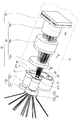
- FIG. 2 is a perspective view of the imaging unit provided in the distal end portion of FIG. 1
- FIG. 3 is a diagram showing the actuator unit in the imaging unit of FIG. 2 together with the first optical system, the second optical system, and the diaphragm plate. It is a perspective view shown seeing from inside III direction.
- FIG. 4 is a perspective view showing the actuator unit in which the first optical path of the first optical system in FIG. 3 is shielded by a light-shielding shutter together with the first optical system, the second optical system, and the diaphragm plate.
- FIG. 5 is an enlarged perspective view showing the actuator unit in FIGS. 3 and 4.
- an imaging unit 25 is provided in the distal end portion 11.
- the imaging unit 25 includes a first optical system 21 that observes the inside of the subject, and a second optical system 22 that observes the inside of the subject having a parallax with the first optical system 21.
- a diaphragm plate 27 is provided.
- the first optical system 21 includes an objective lens 21a and a lens group 21b positioned behind the objective lens 21a, and the objective lens 21a is provided on the distal end surface 11s (see FIG. 1) of the distal end portion 11. It is provided to be exposed.
- the second optical system 22 includes an objective lens 22a and a lens group 22b positioned behind the objective lens 22a, and the objective lens 22a is exposed in the distal end surface 11s in the distal end portion 11.
- the first optical system 21 is juxtaposed.
- the iris diaphragm plate 27 is adhered to the base end surfaces of the lens group 21b and the lens group 22b.
- the aperture plate 27 is formed with an aperture 27a for limiting the first light beam passing through the first optical system 21 and an aperture 27b for limiting the second light beam passing through the second optical system 22.
- the imaging unit 25 includes a rear lens group 23 composed of lenses 23a, 23b, and 23c behind the diaphragm plate 27, and an imaging element 24 behind the lens 23c.
- the image pickup device 24 is configured by a first image of the observation site of the subject observed through the first optical system 21, the aperture 27a, and the rear lens group 23 by drive control of a CPU 80 (see FIG. 6) described later.
- a second image having a parallax with the first image of the observation site of the subject observed through the second optical system 22, the aperture 27b, and the rear lens group 23 is caused by a time difference by a light-shielding shutter 35 described later.
- the first image and the second image are individually captured by forming an image on the entire light receiving surface 24j with a time difference of 1/30 second.
- the imaging unit 25 includes an actuator unit 30 that is located near the first optical system 21 and the second optical system 22 below the first optical system 21 and the second optical system 22. Yes.
- the actuator unit 30 includes a holding member 31, a magnet rotor 32, a rotating shaft 33, a light shielding shutter 35, a yoke 38, detection coils 41 and 42, and a drive coil 44. , 45 and the main part is configured.
- the holding member 31 is located in the vicinity of the first optical system 21 and the second optical system 22 below the first optical system 21 and the second optical system 22.
- a rotation shaft 33, a magnet rotor 32, a fixing portion 35b (to be described later) of the light shielding shutter 35, a yoke 38, detection coils 41 and 42, and drive coils 44 and 45 are provided inside, a rotation shaft 33, a magnet rotor 32, a fixing portion 35b (to be described later) of the light shielding shutter 35, a yoke 38, detection coils 41 and 42, and drive coils 44 and 45 are provided.
- the rotating shaft 33 is rotatably held with respect to the holding member 31, and has an N pole on one half of the outer periphery on the tip side of the rotating shaft 33.
- a ring-shaped magnet rotor 32 having an S pole formed in the other half is fixed. That is, the magnet rotor 32 rotates integrally with the rotation shaft 33.
- a fixing portion 35 b of the light shielding shutter 35 is fixed to the base end of the rotation shaft 33.
- the light shielding shutter 35 is formed in a thin plate shape from a non-magnetic material and includes a light shielding portion 35 a and a fixed portion 35 b, and a main portion is formed.
- the fixing portion 35 b is fixed to the base end of the rotating shaft 33. Thus, it can be rotated together with the rotation shaft 33.
- the light-shielding shutter 35 has a first position shown in FIG. 4 where the light-shielding part 35 a shields the first optical path 21 d of the first optical system 21, and the light-shielding part 35 a is the second optical system 22. It is rotatable between the second position shown in FIG. 3 that blocks the second optical path 22d.
- the first position is defined by the light shielding shutter 35 coming into contact with the stopper 31 b of the holding member 31, and the second position is prescribed by the light shielding shutter 35 coming into contact with the stopper 31 a of the holding member 31. .
- a magnetic body 39 is provided on the surface of the fixed portion 35 b of the light shielding shutter 35 that faces the detection coils 41 and 42.
- the magnetic body 39 may be formed integrally with the fixed portion 35b.
- the yoke 38 is made of a ferromagnetic material.
- the yoke 38 is located on the base end side in the insertion direction S (hereinafter simply referred to as the base end side) and has a U-shaped portion 38u having a U shape that passes through the hollow portions 44c, 45c of the drive coils 44, 45.
- a yoke 38a that covers one side of the outer circumference of the magnet rotor 32 and a yoke 38b that faces the yoke 38a and covers the other side of the outer circumference of the magnet rotor 32.
- the yokes 38a and 38b have different magnetic poles due to the generation of a magnetic field when a direct current is applied to the drive coils 44 and 45. That is, when the yoke 38a is N pole, the yoke 38b is S pole, and when the yoke 38a is S pole, the yoke 38b is N pole.
- the direction of the magnetic poles generated in the yokes 38a and 38b is reversed depending on the direction of the direct current applied to the drive coils 44 and 45.
- the yoke 38a is the N pole and the yoke 38b is the S pole
- the S pole is located on the side of the magnet rotor 32 facing the yoke 38a and the N pole is located on the side facing the yoke 38b
- the magnet rotor 32 that is, the rotating shaft 33 is rotated by attracting each N pole-S pole.
- the light shielding shutter 35 is rotated until the light shielding shutter 35 contacts the stopper 31a. At this time, the light-shielding shutter 35 is rotated to the position defined by the stopper 31a without completely rotating to the position where each N pole and S pole face each other.
- the yoke 38a is an N pole and the yoke 38b is an S pole
- the N pole is located on the side of the magnet rotor 32 facing the yoke 38a
- the S pole is located on the side facing the yoke 38b. Since the N pole-N pole and the S pole-S pole repel each other, the magnet rotor 32, that is, the rotary shaft 33 rotates until the N pole-S pole attract each other.
- the light shielding shutter 35 is rotated until the light shielding shutter 35 contacts the stopper 31b. At this time, the light-shielding shutter 35 is rotated to the position defined by the stopper 31b without completely rotating to the position where each N pole and S pole face each other.
- the light shielding portion 35a of the light shielding shutter 35 fixed to the rotation shaft 33 is rotatable between the first position and the second position.
- the rotation direction of the rotation shaft 33 changes depending on the direction of the direct current applied to the drive coils 44 and 45.
- it is fixed by the stoppers 31a and 31b without rotating until each N pole and S pole are in a position facing each other. Therefore, for example, when the yoke 38a is changed from the N pole to the S pole, the switching of the light shielding shutter 35 is facilitated as compared with the case where each N pole and the S pole are in a position facing each other. In addition, you may rotate until it becomes a position where each N pole and S pole face each other.
- the drive coils 44 and 45 are supplied with a direct current from a direct-current power supply circuit unit 81 (see FIG. 6) described later by drive control of a CPU 80 (see FIG. 6) described later.
- a direct-current power supply circuit unit 81 see FIG. 6
- the light shielding shutter 35 is rotated from the first position to the second position or from the second position to the first position.
- the holding members 31 are arranged side by side.
- the detection coils 41 and 42 are arranged side by side in the rotation region R1 of the magnetic body 39 as the light shielding shutter 35 rotates. Specifically, the detection coil 41 is fixed in contact with the upper surface of the drive coil 44, and the detection coil 42 is fixed in contact with the upper surface of the drive coil 45.
- the detection coils 41 and 42 are arranged side by side so that at least the hollow portions 41c and 42c are positioned in the rotation region R1.
- the detection coils 41 and 42 are magnetic field directions J1 in the hollow portions 41c and 42c of the detection coils 41 and 42 and magnetic field directions in the hollow portions 44c and 45c of the drive coils 44 and 45 with respect to the drive coils 44 and 45.
- J2 and J2 are arranged in parallel.
- the detection coil 41 is provided at a position where the hollow portion 41c is blocked by the magnetic body 39 in the first position described above, and the detection coil 42 is formed as shown in FIG. In the second position described above, the hollow portion 42 c is provided at a position where it is blocked by the magnetic body 39.
- the magnetic body 39 blocks the hollow portion 41c of the detection coil 41 and opens the hollow portion 42c of the detection coil 42.
- the hollow portion 42c is blocked and the hollow portion 41c is opened and shaped.
- the light blocking portion 35a of the light blocking shutter 35 can block the first optical path 21d when the magnetic body 39 blocks the hollow portion 41c, and can block the second optical path when blocking the hollow portion 42c. It is formed in a shape and size that can block 22d.
- the detection coil 41 is formed with a greater number of coil wire turns than the detection coil 42.
- the detection coils 41 and 42 are provided with an alternating current from an AC power supply circuit unit 82 (see FIG. 6), which will be described later, by a drive control of a CPU 80 (see FIG. 6) which will be described later. This is used when detecting the movement of the light blocking shutter 35 by detecting whether the block 39 is blocked or not from the change in the alternating current value.
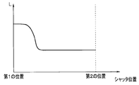
- FIGS. 6 is a block diagram schematically showing a circuit of the endoscope apparatus of FIG. 1 for moving and detecting the movement of the light shielding shutter of FIG. 5, and FIG. 7 is a diagram accompanying the movement of the light shielding shutter of FIG. 6 is a chart showing an inductance change between a first position and a second position detected by an inductance detection unit 6;
- the endoscope apparatus 100 includes a CPU 80 that is a control unit, a DC power supply circuit unit 81 that is a DC power supply, an AC power supply circuit unit 82 that is an AC power supply, and an inductance in the apparatus main body 50. And a detection unit 83.
- the CPU 80, the DC power supply circuit unit 81, the AC power supply circuit unit 82, and the inductance detection unit 83 may be provided in the endoscope 1.
- the DC power supply circuit unit 81 is electrically connected to the CPU 80 and the drive coils 44 and 45, and applies a DC current to the drive coils 44 and 45 by the drive control of the CPU 80.
- the AC power supply circuit unit 82 is electrically connected to the CPU 80, the detection coils 41 and 42, and the inductance detection unit 83, and applies an AC current to the detection coils 41 and 42 by the drive control of the CPU 80.
- the AC power supply circuit unit 82 may always apply an AC current to the detection coils 41 and 42 when the endoscope apparatus 100 is turned on, and only when the rotational position of the light shielding shutter 35 is detected. An alternating current may be applied.
- the inductance detection unit 83 is electrically connected to the detection coils 41 and 42, the AC power supply circuit unit 82, and the CPU 80, and the magnetic body 39 causes the hollow portions 41c and 42c of the detection coils 41 and 42 to be controlled by the drive control of the CPU 80. This is to detect a change in inductance L (see FIG. 7), which will be described later, which occurs when the shielding is performed.
- the CPU 80 is electrically connected to a measurement switch 15 i and a monitor 55 in addition to a DC power supply circuit unit 81, an AC power supply circuit unit 82, and an inductance detection unit 83.
- the CPU 80 When the measurement switch 15i is turned on by the operator, the CPU 80 performs control to apply a direct current to the drive coils 44 and 45 via the direct-current power supply circuit unit 81, thereby moving the light-shielding shutter 35 to the second position.
- the first image is formed on the light receiving surface 24j of the image sensor 24, and the light shielding shutter 35 is moved to the first position to form the second image on the light receiving surface 24j.
- the above-described method is used to measure the size, depth, and the like of the observation region from the first image and the second image that are still images captured with a time difference.
- the CPU 80 performs control for applying an alternating current to the detection coils 41 and 42 via the alternating-current power supply circuit unit 82, whereby the inductance when the magnetic field generated in the hollow portions 41 c and 42 c is blocked by the magnetic body 39.
- the change in L from the value of the alternating current via the inductance detector 83, the rotational movement of the light shielding shutter 35 is detected.
- the CPU 80 determines that the magnetic body 39 has the hollow portions 41 c and 42 c of the detection coils 41 and 42 in the first position and the second position as the light shielding shutter 35 rotates.
- the difference Lx due to the difference in the number of windings of the detection coils 41 and 42 of the inductances L1 and L2 generated by blocking the magnetic field of the first through the inductance detector 83, the light-shielding shutter 35 becomes the first. It is detected that the position has been moved from the second position to the second position or has been moved from the second position to the first position.
- the light shielding shutter 35 has the magnetic body 39 in the hollow portion 41c as shown in FIG. And the light shielding portion 35a is moved to the first position where the first optical path 21d is shielded, and when it is detected that the value of the inductance L is decreased by Lx and becomes L2, the light shielding shutter 35 is shown in FIG. As shown in FIG. 3, it is detected that the magnetic body 39 has closed the hollow portion 42c and the light blocking portion 35a has moved to the second position blocking the second optical path 22d.
- the CPU 80 has a value of the inductance L generated when the magnetic body 39 opens the magnetic field of the hollow portions 41 c and 42 c of the detection coils 41 and 42 as the light shielding shutter 35 rotates.
- L3 which is significantly reduced from L1 and L2
- the inductance detection unit 83 it is detected that the light shielding shutter 35 is located between the first position and the second position.
- the CPU 80 does not move the light-shielding shutter 35 when the change in the inductance L cannot be detected even when the direct current is applied to the drive coils 44 and 45 while the alternating current is applied to the detection coils 41 and 42.
- the state is detected via the inductance detection unit 83, and the measured value of the observation site obtained via the imaging element 24 is the result of the tip 11 moving as described above, and as a result, the same optical system is used.
- control is performed to warn the user of an inaccurate value obtained from two images captured with a time difference through the monitor 55, for example.
- the warning is not limited to display but may be sound.
- the light-shielding shutter 35 is shielded by the magnetic body 39 shown in FIG. 4 and the light-shielding portion 35a is the first.
- the light blocking shutter 35 rotates in one direction from the first position by the stopper 31b provided on the holding member 31. It is prevented.
- the yoke 38 works as a ferromagnetic material, so that the poles closer to the yoke of the N and S poles of the magnet rotor are attracted. .
- the light-shielding shutter 35 moves from the first position. There is no.
- the CPU 80 controls the direct current power supply circuit 81 to apply direct current to the drive coils 44 and 45. Then, AC current is applied to the detection coils 41 and 42 by driving and controlling the AC power supply circuit unit 82.
- the CPU 80 detects that the value of the inductance L is L1 through the inductance detection unit 83 from the current value of the alternating current by the magnetic body 39 blocking the hollow portion 41c and opening the hollow portion 42c. Therefore, the CPU 80 detects that the light shielding shutter 35 is located at the first position.
- the CPU 80 may display on the monitor 55 that the light shielding shutter 35 is located at the first position.
- the light shielding shutter 35 is positioned between the first position and the second position in a state where the application of direct current from the CPU 80 to the drive coils 44 and 45 is stopped by a foreign object or the like.
- the CPU 80 causes the DC power supply circuit unit 81 to By controlling the drive, a direct current is applied to the drive coils 44 and 45, and an alternating current is applied to the detection coils 41 and 42 by controlling the drive of the AC power supply circuit unit 82.
- the CPU 80 detects that the light blocking shutter 35 is located between the first position and the second position via the inductance detection unit 83.
- the CPU 80 displays a warning on the monitor 55.
- the yoke 38a of the yoke 38 becomes the N pole, and the yoke 38b becomes the south pole.
- the N pole of the magnet rotor 32 repels the N pole of the yoke 38a
- the S pole of the magnet rotor repels the S pole of the yoke 38b
- the S pole of the magnet rotor 32 attracts the N pole of the yoke 38a.
- the magnet rotor 32 rotates in the other direction by pulling the north pole of the magnet rotor to the south pole of the yoke 38b.
- the light blocking shutter 35 moves to the second position where the magnetic body 39 shown in FIG. 3 blocks the hollow portion 42c and the light blocking portion 35a blocks the second optical path 22d.
- the light blocking shutter 35 is prevented from rotating in the other direction than the second position by the stopper 31a provided on the holding member 31.
- the CPU 80 determines that the value of the inductance L has decreased from L1 to L2 by the magnetic body 39 blocking the hollow portion 42c and opening the hollow portion 41c, that is, the difference Lx is the current value of the alternating current. Is detected via the inductance detector 83. Therefore, the CPU 80 detects that the light shielding shutter 35 has moved to the second position. The CPU 80 may display on the monitor 55 that the light shielding shutter 35 has moved to the second position.
- the CPU 80 detects that the light shielding shutter 35 has not moved to the second position, and displays a warning on the monitor 55.
- the light shielding shutter 35 After the light shielding shutter 35 has moved to the second position, it has passed through the first optical path 21d to the light receiving surface 24j of the image sensor 24 via the first optical system 21, the aperture 27a, and the rear lens group 23.
- the first light beam forms an image, and the first image is captured.
- the CPU 80 stops the direct current application control to the drive coils 44 and 45.
- the yoke 38b works as a ferromagnetic material, so that the poles closer to the yoke out of the N pole and S pole of the magnet rotor are attracted. Therefore, in this case, since the attracting between the N pole of the yoke 38a and the S pole of the magnet rotor 32 and the attracting between the S pole of the yoke 38b and the N pole of the magnet rotor 32 are maintained, the light-shielding shutter 35 moves from the second position. There is no end.
- the light shielding shutter 35 when the light shielding shutter 35 is moved from the second position to the first position, it is opposite to when the light shielding shutter 35 is moved from the first position to the second position to the drive coils 44 and 45.
- the yoke 38a of the yoke 38 becomes the S pole and the yoke 38b becomes the N pole.
- the S pole of the magnet rotor 32 repels the S pole of the yoke 38a
- the N pole of the magnet rotor repels the N pole of the yoke 38b
- the N pole of the magnet rotor 32 attracts the S pole of the yoke 38a.
- the magnet rotor 32 rotates in one direction by pulling the south pole of the magnet rotor to the north pole of the yoke 38b.
- the light blocking shutter 35 moves to the first position where the magnetic body 39 shown in FIG. 4 blocks the hollow portion 41c and the light blocking portion 35a blocks the first optical path 21d. Note that the light shielding shutter 35 is prevented from rotating more than the first position in one direction by the stopper 31 b provided on the holding member 31.
- the CPU 80 determines that the value of the inductance L has increased from L2 to L1 by the magnetic body 39 blocking the hollow portion 41c and opening the hollow portion 42c, that is, the difference Lx is the current value of the alternating current. Is detected via the inductance detector 83. Therefore, the CPU 80 detects that the light shielding shutter 35 has moved to the first position. The CPU 80 may display on the monitor 55 that the light shielding shutter 35 has moved to the first position.
- the CPU 80 detects that the light shielding shutter 35 has not moved to the first position, and displays a warning on the monitor 55.
- the light blocking shutter 35 After the light blocking shutter 35 has moved to the first position, it has passed through the second optical path 22d to the light receiving surface 24j of the image sensor 24 via the second optical system 22, the aperture 27b, and the rear lens group 23.
- the second light beam forms an image, and a second image is captured.
- the CPU 80 stops the direct current application control to the drive coils 44 and 45.
- the yoke 38 functions as a ferromagnetic material, so the side closer to the yoke of the N and S poles of the magnet rotor. Is attracted. Accordingly, in this case, since the attracting between the north pole of the yoke 38a and the magnet rotor 32 and the attracting between the north pole of the yoke 38b and the south pole of the magnet rotor 32 are maintained, the light-shielding shutter 35 moves from the first position. There is no.
- the CPU 80 measures the observation region from the first image and the second image that are still images captured by the image sensor 24.
- the case where the second image is picked up after the first image is picked up has been described as an example, but it is needless to say that the opposite may be the case.
- the CPU 80 applies a direct current to the drive coils 44 and 45 and moves the light shielding shutter 35 in a state where an alternating current is applied to the detection coils 41 and 42, the magnetic body 39 has the hollow portion 41 c.
- the light shielding shutter 35 is shielded, it is shown that the light shielding shutter 35 is moved to the first position that shields the first optical path 21d by detecting the inductance L1 via the inductance detector 83.
- the CPU 80 detects the inductance L2 via the inductance detection unit 83, and detects the difference Lx of the inductance L, whereby the light shielding shutter 35 is in the second state.
- the CPU 80 detects the value L3 that is significantly reduced from the L1 and L2 values in the inductance L via the inductance detection unit 83, thereby blocking the light. It has been shown that the shutter 35 detects that the shutter 35 has moved between the first position and the second position that do not block the first optical path 21d and the second optical path 22d.
- the CPU 80 indicates that a warning is displayed on the monitor 55 when the light-shielding shutter 35 is in a non-moving state even though direct current application control is performed on the drive coils 44 and 45.
- the warning display is not displayed on the monitor 55 after the operator turns on the measurement switch 15i, the first image captured through the first optical path 21d and the second optical path are displayed. It can be easily confirmed from the second image picked up via 22 that the observation site has been accurately measured.
- the distal end portion 11 in which the actuator unit 30 is provided has a smaller diameter than when a conventional Hall element is used. And shortening in the insertion direction S.
- the detection coils 41 and 42 are fixed in contact with the upper surfaces of the drive coils 44 and 45 and the magnetic field directions J1 and J2 are orthogonal to each other, the detection coils 41 and 42 can be arranged in a compact manner.
- the tip 11 can be reduced in diameter and shortened in the insertion direction S.
- the actuator unit 30 is compactly disposed in the empty space below the first optical system 21 and the second optical system 22 in the distal end portion 11, the diameter of the distal end portion 11 is smaller than that of the conventional one.
- the insertion direction S can be shortened.
- the endoscope apparatus 100 having a configuration that can accurately detect the movement of the light-shielding shutter 35 so that the measurement of the observation site with high accuracy and accuracy can be realized together with the diameter reduction and shortening of the distal end portion 11. it can.
- the detection coil 41 has a larger number of turns of the coil wire than the detection coil 42, so that the value L1 of the inductance L at the first position is the second value. It has been shown that the CPU 80 detects whether the light shielding shutter 35 is moved to the first position or the second position by being larger than the value L2 of the inductance L at the position by Lx.
- the number of windings of the coil wires of the detection coils 41 and 42 is the same, and whether the light shielding shutter 35 has moved to the first position depending on the direction of the direct current applied to the drive coils 44 and 45. It may also be detected whether or not it has moved to the second position.
- FIG. 8 is a block diagram schematically showing a circuit of the endoscope apparatus of FIG. 1 that moves the light-shielding shutter and detects the movement in a modification in which the drive coil and the detection coil of FIG. 6 are connected in series. is there.
- the DC power supply circuit unit 81 is electrically connected to the drive coils 44 and 45, and the DC power supply circuit unit 81 is connected to the DC drive circuit 44 and 45 by the drive control of the CPU 80. It was shown that current was applied.
- an AC power supply circuit unit 82 is electrically connected to the detection coils 41 and 42, and an AC current is applied to the detection coils 41 and 42 from the AC power supply circuit unit 82 by drive control of the CPU 80. It was.
- the drive coils 44, 45 and the detection coils 41, 42 are connected in series, and the CPU 80 receives the DC current from the DC power supply circuit unit 81 and the AC power supply circuit unit 82.
- the alternating current may be superposed in the superimposing unit 84, and control may be performed in which the direct current and the alternating current are superimposed and applied to the drive coils 44 and 45 and the detection coils 41 and 42.
- the control of the CPU 80 for rotating the light-shielding shutter 35 and the control of the CPU 80 for detecting the movement of the light-shielding shutter 35 are the same as those in the embodiment described above except that the direct current and the alternating current are applied in a superimposed manner. Is the same.
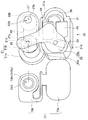
- FIG. 9 shows an actuator unit of the imaging unit provided in the distal end portion of the insertion portion of the endoscope in the endoscope apparatus of the present embodiment, together with the first optical system, the second optical system, and the diaphragm plate.
- FIG. 10 is a perspective view showing an actuator unit in which the first optical path of the first optical system in FIG. 9 is blocked by a light-shielding shutter together with the first optical system, the second optical system, and the diaphragm plate. .
- FIG. 11 shows the inductance detection when the magnetic material blocks the hollow portion of the detection coil in FIGS. 9 and 10 for a certain time as the light shielding shutter moves between the first position and the second position. It is a graph which shows the inductance change detected by the part.
- the configuration of the endoscope apparatus of the second embodiment is composed of only one detection coil as compared with the endoscope apparatus of the first embodiment shown in FIGS. 1 to 7 described above. Is different. Therefore, only this difference will be described, the same reference numerals are given to the same components as those in the first embodiment, and the description thereof will be omitted.
- the actuator unit 30 includes a holding member 31, a magnet rotor 32, a rotating shaft 33, a light shielding shutter 35, a yoke 38, and a drive coil 44. , 45 and the detection coil 140, the main part is configured.
- the light-shielding shutter 35 has the first position shown in FIG. 10 where the light-shielding portion 35a blocks the first optical path 21d of the first optical system 21, and the light-shielding portion 35a is the second optical. It can freely rotate between the second position shown in FIG. 9 that blocks the second optical path 22d of the system 22.
- the structure which moves the light-shielding shutter 35 between the 1st position and the 2nd position using the drive coils 44 and 45 is the same as 1st Embodiment mentioned above.
- the magnetic body 39 is provided on the surface of the fixed portion 35b of the light shielding shutter 35 that faces the detection coil 140.
- the magnetic body 39 is moved to the first position when the light-shielding shutter 35 moves between the first position and the second position. Between the first position and the second position, the hollow portion 140c of the detection coil 140 is blocked, and when moved to the first position or the second position, the hollow portion 140c is opened and formed in a size and shape. Yes.
- the magnetic body 39 may be formed in a size that covers the entire surface of the light shielding shutter 35. Further, the light shielding shutter 35 itself may be composed of the magnetic body 39.
- the detection coil 140 is composed of one, and the detection coil 140 has at least the hollow portion 140 c accompanying the rotation of the light shielding shutter 35.
- the magnetic body 39 is located in the rotation region R1. Specifically, the detection coil 140 is fixed on the upper surface of the drive coils 44 and 45 in contact with the position between the drive coil 44 and the drive coil 45.
- the detection coil 140 has a magnetic field direction J1 in the hollow portion 140c of the detection coil 140 and a hollow portion 44c of the drive coils 44, 45 with respect to the drive coils 44, 45.
- the magnetic field direction J2 in 45c is provided so as to be orthogonal.
- the detection coil 140 is provided at a position between the first position and the second position of the light shielding shutter 35, as shown in FIGS.
- the light blocking portion 35a of the light blocking shutter 35 is formed in a shape and size that does not block both the first optical path 21d and the second optical path 22d. ing. In other words, when the magnetic body 39 does not block the hollow portion 140c, it is formed in a shape and size that block either the first optical path 21d or the second optical path 22d.
- the detection coil 140 detects the movement of the light-shielding shutter 35 by detecting whether or not the magnetic body 39 blocks the hollow portion 140c when an alternating current is applied from the alternating-current power supply circuit portion 82 by the drive control of the CPU 80. This is what is used.
- the AC power supply circuit unit 82 applies an AC current to the detection coil 140 under the drive control of the CPU 80.
- the AC power supply circuit unit 82 may always apply an AC current to the detection coil 140 when the endoscope apparatus 100 is turned on, and the rotational position of the light shielding shutter 35 may be changed. An alternating current may be applied only when detecting.
- the inductance detector 83 detects a change in the inductance L when the magnetic body 39 blocks the hollow portion 140c of the detection coil 140 by the drive control of the CPU 80.
- the CPU 80 performs control for applying an alternating current to the detection coil 140 via the alternating-current power supply circuit unit 82, thereby blocking the magnetic field generated in the hollow portion 140 c by the magnetic body 39.
- the change in the inductance L at that time is detected from the value of the alternating current via the inductance detector 83, thereby detecting the rotational movement of the light shielding shutter 35.
- the CPU 80 temporarily changes the magnetic field of the hollow portion 140 c as the magnetic body 39 moves between the first position and the second position of the light shielding shutter 35.
- the light blocking shutter 35 has moved from the first position to the second position or from the second position to the first position. Detect that it has moved to.
- the CPU 80 cannot detect the change in the inductance L even if the direct current is applied to the drive coils 44 and 45, and the light shielding shutter 35 is in the non-moving state. For example, it is detected that the measured value of the observed region obtained through the image pickup device 24 is inaccurate, for example, through a monitor 55.
- the warning is not limited to display but may be sound.
- the light shielding shutter 35 when the light shielding shutter 35 is moved from the first position to the second position or from the second position to the first position by applying a direct current to the drive coils 44 and 45, the light shielding shutter. With the movement of 35, the magnetic body 39 temporarily blocks the movement while moving the hollow portion 140 c of the detection coil 140.
- the CPU 80 indicates that the value of the inductance L has temporarily increased as shown in FIG. 11 due to the magnetic body 39 temporarily blocking the magnetic field of the hollow portion 140c at a certain time t.
- the change is detected from the change in current value via the inductance detector 83. Therefore, the CPU 80 detects that the light shielding shutter 35 has moved from the first position to the second position or from the second position to the first position.
- the CPU 80 may display on the monitor 55 that the light shielding shutter 35 has moved to the first position or the second position.
- the CPU 80 detects that the light shielding shutter 35 has not moved to the first position or the second position, and displays a warning on the monitor 55.
- the light shielding shutter 35 since only one detection coil is provided, the light shielding shutter 35 has moved from the first position to the second position, or the first position from the second position.
- the movement to the position can be detected, but as in the first embodiment described above, the rotation direction of the light shielding shutter 35, that is, whether the light shielding shutter 35 has moved to the first position,
- the detection coil 140 cannot detect whether it has moved to position 2.
- the configuration of the actuator unit 30 is simplified, and the diameter and the size of the distal end portion 11 are further reduced as compared with the first embodiment. can do.
- Other effects are the same as those of the first embodiment described above.
- FIG. 12 shows a state between the first position and the second position of the light-shielding shutter detected by the inductance detection unit when the detection coils of FIGS. 9 and 10 are provided at the first position or the second position. It is a graph which shows an inductance change.
- the detection coil 140 is shown to be provided at a position between the first position and the second position in the rotation region R1 of the magnetic body 39.
- the detection coil 140 may be provided at the first position or the second position in the rotation region R1.
- the magnetic body 39 blocks the hollow portion 140c of the detection coil 140 when the light shielding shutter 35 moves to the first position, and opens the hollow portion 140c when moved to the second position. Is formed into a shape.
- the CPU 80 causes the magnetic body 39 to move with the movement of the light shielding shutter 35 from the second position to the first position. If the hollow portion 140c of the detection coil 140 is blocked at the first position, it is possible to detect that the inductance L has significantly increased as shown in FIG. 12, and therefore the light-shielding shutter 35 is moved from the second position to the first position. It is possible to constantly detect the movement to the position.
- the CPU 80 as shown in FIG. 12, if the magnetic body 39 opens the hollow portion 140c of the detection coil 140 at the second position as the light shielding shutter 35 moves from the first position to the second position. Since it is possible to detect that the inductance L is significantly reduced, it is possible to steadily detect that the light shielding shutter 35 has moved from the first position to the second position. The above is the same even when the detection coil 140 is provided at the second position. Other effects are the same as those of the present embodiment described above.
- FIG. 13 shows a configuration in which a detection coil is provided on a flexible substrate that can be attached to and detached from the actuator unit of the imaging unit provided in the distal end portion of the insertion portion of the endoscope in the endoscope apparatus of the present embodiment. It is a perspective view shown.
- the configuration of the endoscope apparatus of the third embodiment is the same as that of the endoscope apparatus of the first embodiment shown in FIGS. 1 to 7 and the second embodiment shown in FIGS. Compared to an endoscope apparatus, the difference is that a detection coil is formed on a flexible substrate. Therefore, only this difference will be described, the same reference numerals are given to the same components as those in the first and second embodiments, and the description thereof will be omitted.
- a flexible substrate 70 is detachably attached to the actuator unit 30.
- the flexible substrate 70 includes a first part 70 a attached to the base end face of the holding member 31 and a second part 70 b attached to the part overlapping the first optical system 21 on the base end face of the diaphragm plate 27.
- the main part is composed of
- An opening 70bc having substantially the same size as the aperture hole 27a is formed at a position overlapping the aperture hole 27a of the aperture plate 27 in the second portion 70b.
- the opening 70bc allows the first light beam to enter the rear lens group 23.
- a detection coil 240 formed as a coil pattern is provided at a position surrounding the opening 70bc on the base end face of the second portion 70b. Therefore, the opening 70bc constitutes a hollow portion 240c of the detection coil 240.
- the light shielding shutter 35 includes the first position where the light shielding portion 35 a blocks the first optical path 21 d of the first optical system 21 and the light shielding portion 35 a of the second optical system 22.
- the second optical path 22d is rotatable between the second position and the second position.
- the configuration in which the light-shielding shutter 35 is moved between the first position and the second position using the drive coils 44 and 45 is the same as in the first and second embodiments described above.
- the magnetic body 39 is provided on the surface of the light shielding portion 35 a of the light shielding shutter 35 that faces the detection coil 240.
- the magnetic body 39 shields the hollow portion 240c of the detection coil 240, and when moved to the second position, the magnetic body 39 is sized and shaped to open the hollow portion 240c. Is formed.
- the magnetic body 39 may be formed in a size that covers the entire surface of the light-shielding shutter 35 as in the second embodiment. Further, the light shielding shutter 35 itself may be composed of the magnetic body 39.
- the detection coil 240 is composed of one, and after the second portion 70b of the flexible substrate 70 is attached to the diaphragm plate 27, the light shielding shutter 35 is the first optical path.
- the magnetic body 39 is provided at a first position for closing the hollow portion 240c while closing the 21d. That is, the detection coil 240 is provided at the first position of the light shielding shutter 35 in the region R2 in which at least the hollow portion 240c connects the first optical path 21d and the second optical path 22d.
- the detection coil 240 has a magnetic field direction J1 in the hollow portion 240c of the detection coil 240 and a hollow portion 44c of the drive coils 44, 45 with respect to the drive coils 44, 45.
- the magnetic field direction J2 in 45c is provided so as to be orthogonal.
- the CPU 80 causes the magnetic body 39 to move to the first position as the light shielding shutter 35 moves from the second position to the first position. If the hollow portion 240c of the detection coil 240 is blocked in FIG. 12, it is possible to detect that the inductance L has significantly increased, as shown in FIG. 12, and the light shielding shutter 35 is moved from the second position to the first position. The movement can be detected constantly.
- the magnetic body 39 opens the hollow portion 240c of the detection coil 240 at the second position as the light shielding shutter 35 moves from the first position to the second position, as shown in FIG. Since it is possible to detect that the inductance L is significantly reduced, it is possible to steadily detect that the light shielding shutter 35 has moved from the first position to the second position. The above is the same even when the detection coil 240 is provided at the second position by the flexible substrate 70.
- the same operation and effect as in the second embodiment can be produced. I do not care.
- the first position and the first position of the region R2 By locating the detection coil at position 2, the same operation and effect as in the first embodiment may be produced.
- the detection coil can be provided separately from the actuator unit 30, that is, it can be provided separately from the holding member 31, the holding member 31 can be reduced in size.
- the wiring to the detection coil is simplified, and the workability and the assemblability are improved. If miniaturization is ignored, the detection coil may be provided in the holding member 31 using the flexible substrate 70. The other effects are the same as those of the first and second embodiments described above.
- the detection coils 41, 42, and 140 are shown to be provided in the region R ⁇ b> 1 so as to contact the upper surfaces of the drive coils 44 and 45.
- the diaphragm plate 27 may be fixed to the diaphragm plate 27 in the region R2 on the base end face.
- the CPU 80 measures the observation region from the two still images of the first image and the second image captured by the image sensor 24.
- the present invention is not limited to this, and the first image and the second image are three-dimensionally obtained from the plurality of first images and second images by repeatedly capturing the first image and the second image with a time difference by moving the light shielding shutter 35. Needless to say, it is also possible to take a moving image and measure the observation site from the moving image.
- the CPU 80 when detecting the movement of the light shielding shutter 35, the CPU 80 continuously detects, for example, three times that a change in the inductance L cannot be detected after applying a direct current to the drive coils 44 and 45. Only when this is not possible, a warning may be displayed on the monitor 55.
- an industrial endoscope apparatus has been described as an example, but it goes without saying that the present invention may be applied to a medical endoscope apparatus. Absent.
Abstract
Priority Applications (4)
| Application Number | Priority Date | Filing Date | Title |
|---|---|---|---|
| EP14820690.7A EP3017747B1 (fr) | 2013-07-04 | 2014-05-16 | Endoscope |
| JP2015525085A JP6265988B2 (ja) | 2013-07-04 | 2014-05-16 | 内視鏡装置 |
| CN201480038471.XA CN105358040B (zh) | 2013-07-04 | 2014-05-16 | 内窥镜装置 |
| US14/987,102 US9967442B2 (en) | 2013-07-04 | 2016-01-04 | Endoscope apparatus |
Applications Claiming Priority (2)
| Application Number | Priority Date | Filing Date | Title |
|---|---|---|---|
| JP2013140808 | 2013-07-04 | ||
| JP2013-140808 | 2013-07-04 |
Related Child Applications (1)
| Application Number | Title | Priority Date | Filing Date |
|---|---|---|---|
| US14/987,102 Continuation US9967442B2 (en) | 2013-07-04 | 2016-01-04 | Endoscope apparatus |
Publications (1)
| Publication Number | Publication Date |
|---|---|
| WO2015001852A1 true WO2015001852A1 (fr) | 2015-01-08 |
Family
ID=52143445
Family Applications (1)
| Application Number | Title | Priority Date | Filing Date |
|---|---|---|---|
| PCT/JP2014/063105 WO2015001852A1 (fr) | 2013-07-04 | 2014-05-16 | Endoscope |
Country Status (5)
| Country | Link |
|---|---|
| US (1) | US9967442B2 (fr) |
| EP (1) | EP3017747B1 (fr) |
| JP (1) | JP6265988B2 (fr) |
| CN (1) | CN105358040B (fr) |
| WO (1) | WO2015001852A1 (fr) |
Cited By (6)
| Publication number | Priority date | Publication date | Assignee | Title |
|---|---|---|---|---|
| KR20180057488A (ko) * | 2016-11-21 | 2018-05-30 | 삼성전기주식회사 | 피크 검출을 이용한 카메라 모듈의 위치 제어 장치 |
| WO2018135133A1 (fr) * | 2017-01-18 | 2018-07-26 | オリンパス株式会社 | Dispositif d'endoscope |
| JP2019053271A (ja) * | 2017-09-12 | 2019-04-04 | サムソン エレクトロ−メカニックス カンパニーリミテッド. | カメラモジュール |
| JP2019138980A (ja) * | 2018-02-07 | 2019-08-22 | オリンパス株式会社 | 内視鏡装置、内視鏡装置の制御方法、内視鏡装置の制御プログラム、および記録媒体 |
| JP2019138982A (ja) * | 2018-02-07 | 2019-08-22 | オリンパス株式会社 | 内視鏡装置、内視鏡装置の制御方法、内視鏡装置の制御プログラム、および記録媒体 |
| US11397314B2 (en) | 2017-12-27 | 2022-07-26 | Olympus Corporation | Endoscope system, optical adaptor for endoscope, and method of controlling endoscope system |
Families Citing this family (4)
| Publication number | Priority date | Publication date | Assignee | Title |
|---|---|---|---|---|
| US11160443B2 (en) * | 2017-03-30 | 2021-11-02 | Hoya Corporation | Electronic endoscope device for changing observation image brightness |
| KR102538913B1 (ko) * | 2018-08-13 | 2023-06-01 | 삼성전기주식회사 | 카메라 모듈 |
| CN109770834A (zh) * | 2019-01-12 | 2019-05-21 | 中北大学 | 一种用于小肠无创诊查的冲击驱动式胶囊机器人机构 |
| JP2022038252A (ja) * | 2020-08-26 | 2022-03-10 | オリンパス株式会社 | 内視鏡装置、内視鏡装置の作動方法、およびプログラム |
Citations (2)
| Publication number | Priority date | Publication date | Assignee | Title |
|---|---|---|---|---|
| JP2010128354A (ja) * | 2008-11-28 | 2010-06-10 | Olympus Medical Systems Corp | ステレオ光学系、並びにそれを用いたステレオ計測用光学装置、ステレオ計測装置及びステレオ観察装置 |
| JP2013253797A (ja) * | 2012-06-05 | 2013-12-19 | Olympus Corp | 計測装置及びプログラム |
Family Cites Families (10)
| Publication number | Priority date | Publication date | Assignee | Title |
|---|---|---|---|---|
| JPH07163517A (ja) * | 1993-12-13 | 1995-06-27 | Toshiba Corp | 立体視内視鏡 |
| JPH0886968A (ja) * | 1994-09-19 | 1996-04-02 | Yaskawa Electric Corp | 光遮断装置 |
| JPH1082957A (ja) * | 1996-09-06 | 1998-03-31 | Yaskawa Electric Corp | 光遮断装置 |
| DE102009049143B3 (de) * | 2009-10-12 | 2010-12-30 | Sopro-Comeg Gmbh | Endoskop |
| JP5417268B2 (ja) * | 2010-06-28 | 2014-02-12 | 富士フイルム株式会社 | 内視鏡システム |
| WO2012002297A1 (fr) * | 2010-06-30 | 2012-01-05 | 富士フイルム株式会社 | Procédé et dispositif d'imagerie |
| JP4971532B1 (ja) * | 2010-12-01 | 2012-07-11 | パナソニック株式会社 | 立体画像撮影装置および内視鏡 |
| JP5383639B2 (ja) * | 2010-12-22 | 2014-01-08 | セイコープレシジョン株式会社 | 羽根駆動装置及び光学機器 |
| JP5973707B2 (ja) * | 2011-10-14 | 2016-08-23 | オリンパス株式会社 | 三次元内視鏡装置 |
| JP5730339B2 (ja) * | 2013-01-25 | 2015-06-10 | 富士フイルム株式会社 | 立体内視鏡装置 |
-
2014
- 2014-05-16 JP JP2015525085A patent/JP6265988B2/ja active Active
- 2014-05-16 EP EP14820690.7A patent/EP3017747B1/fr active Active
- 2014-05-16 WO PCT/JP2014/063105 patent/WO2015001852A1/fr active Application Filing
- 2014-05-16 CN CN201480038471.XA patent/CN105358040B/zh active Active
-
2016
- 2016-01-04 US US14/987,102 patent/US9967442B2/en active Active
Patent Citations (3)
| Publication number | Priority date | Publication date | Assignee | Title |
|---|---|---|---|---|
| JP2010128354A (ja) * | 2008-11-28 | 2010-06-10 | Olympus Medical Systems Corp | ステレオ光学系、並びにそれを用いたステレオ計測用光学装置、ステレオ計測装置及びステレオ観察装置 |
| JP4750175B2 (ja) | 2008-11-28 | 2011-08-17 | オリンパスメディカルシステムズ株式会社 | ステレオ光学系、並びにそれを用いたステレオ計測用光学装置、ステレオ計測装置及びステレオ観察装置 |
| JP2013253797A (ja) * | 2012-06-05 | 2013-12-19 | Olympus Corp | 計測装置及びプログラム |
Cited By (11)
| Publication number | Priority date | Publication date | Assignee | Title |
|---|---|---|---|---|
| KR20180057488A (ko) * | 2016-11-21 | 2018-05-30 | 삼성전기주식회사 | 피크 검출을 이용한 카메라 모듈의 위치 제어 장치 |
| WO2018135133A1 (fr) * | 2017-01-18 | 2018-07-26 | オリンパス株式会社 | Dispositif d'endoscope |
| US11490788B2 (en) | 2017-01-18 | 2022-11-08 | Evident Corporation | Endoscope apparatus |
| JP2019053271A (ja) * | 2017-09-12 | 2019-04-04 | サムソン エレクトロ−メカニックス カンパニーリミテッド. | カメラモジュール |
| JP7135258B2 (ja) | 2017-09-12 | 2022-09-13 | サムソン エレクトロ-メカニックス カンパニーリミテッド. | カメラモジュール |
| US11397314B2 (en) | 2017-12-27 | 2022-07-26 | Olympus Corporation | Endoscope system, optical adaptor for endoscope, and method of controlling endoscope system |
| JP2019138980A (ja) * | 2018-02-07 | 2019-08-22 | オリンパス株式会社 | 内視鏡装置、内視鏡装置の制御方法、内視鏡装置の制御プログラム、および記録媒体 |
| JP2019138982A (ja) * | 2018-02-07 | 2019-08-22 | オリンパス株式会社 | 内視鏡装置、内視鏡装置の制御方法、内視鏡装置の制御プログラム、および記録媒体 |
| JP7012549B2 (ja) | 2018-02-07 | 2022-01-28 | オリンパス株式会社 | 内視鏡装置、内視鏡装置の制御方法、内視鏡装置の制御プログラム、および記録媒体 |
| JP7109729B2 (ja) | 2018-02-07 | 2022-08-01 | 株式会社エビデント | 内視鏡装置、内視鏡装置の制御方法、内視鏡装置の制御プログラム、および記録媒体 |
| US11419482B2 (en) | 2018-02-07 | 2022-08-23 | Olympus Corporation | Endoscope apparatus, control method of endoscope apparatus, and recording medium |
Also Published As
| Publication number | Publication date |
|---|---|
| US20160119521A1 (en) | 2016-04-28 |
| JPWO2015001852A1 (ja) | 2017-02-23 |
| US9967442B2 (en) | 2018-05-08 |
| CN105358040B (zh) | 2018-01-02 |
| CN105358040A (zh) | 2016-02-24 |
| EP3017747B1 (fr) | 2020-09-30 |
| JP6265988B2 (ja) | 2018-01-24 |
| EP3017747A1 (fr) | 2016-05-11 |
| EP3017747A4 (fr) | 2017-04-05 |
Similar Documents
| Publication | Publication Date | Title |
|---|---|---|
| JP6265988B2 (ja) | 内視鏡装置 | |
| JP6188603B2 (ja) | 医療用システム | |
| US8803957B2 (en) | Image pickup unit and endoscope | |
| EP2979615B1 (fr) | Dispositif pour chirurgie endoscopique | |
| JP5450663B2 (ja) | 内視鏡装置の作動方法および内視鏡カプセルのナビゲーション装置 | |
| JPWO2012132638A1 (ja) | 内視鏡システム | |
| JP2959723B2 (ja) | 内視鏡用被検体内挿入装置 | |
| US11259689B2 (en) | Endoscope system, processor and endoscope | |
| EP2979619A1 (fr) | Dispositif pour chirurgie endoscopique | |
| JP2011098051A (ja) | 拡大内視鏡 | |
| JP2007159738A (ja) | 内視鏡装置 | |
| US20190090728A1 (en) | Visualization system comprising an observation apparatus and an endoscope | |
| US20190274526A1 (en) | Stereoscopic image pickup apparatus and stereoscopic endoscope | |
| US10582840B2 (en) | Endoscope apparatus | |
| EP2979613B1 (fr) | Dispositif pour chirurgie endoscopique | |
| JP2020151406A (ja) | 医療用保持装置及び医療用観察システム | |
| EP2982333A1 (fr) | Dispositif chirurgical | |
| JP5379454B2 (ja) | 医療用観察装置及び医療用観察システム | |
| WO2016189736A1 (fr) | Unité optique, dispositif de capture d'image et endoscope | |
| JP5998014B2 (ja) | 撮像装置及び内視鏡装置 | |
| US20220409022A1 (en) | Endoscope and endoscope system | |
| JP5866930B2 (ja) | 眼屈折力測定装置 | |
| JP6694964B2 (ja) | 内視鏡装置 | |
| JP6109023B2 (ja) | 光学ユニット | |
| JP2014155592A (ja) | 内視鏡システム |
Legal Events
| Date | Code | Title | Description |
|---|---|---|---|
| WWE | Wipo information: entry into national phase |
Ref document number: 201480038471.X Country of ref document: CN |
|
| 121 | Ep: the epo has been informed by wipo that ep was designated in this application |
Ref document number: 14820690 Country of ref document: EP Kind code of ref document: A1 |
|
| ENP | Entry into the national phase |
Ref document number: 2015525085 Country of ref document: JP Kind code of ref document: A |
|
| NENP | Non-entry into the national phase |
Ref country code: DE |
|
| WWE | Wipo information: entry into national phase |
Ref document number: 2014820690 Country of ref document: EP |