WO2014208457A1 - トロイダル型無段変速機 - Google Patents
トロイダル型無段変速機 Download PDFInfo
- Publication number
- WO2014208457A1 WO2014208457A1 PCT/JP2014/066387 JP2014066387W WO2014208457A1 WO 2014208457 A1 WO2014208457 A1 WO 2014208457A1 JP 2014066387 W JP2014066387 W JP 2014066387W WO 2014208457 A1 WO2014208457 A1 WO 2014208457A1
- Authority
- WO
- WIPO (PCT)
- Prior art keywords
- disk
- shroud
- continuously variable
- variable transmission
- oil
- Prior art date
Links
Images


Classifications
-
- F—MECHANICAL ENGINEERING; LIGHTING; HEATING; WEAPONS; BLASTING
- F16—ENGINEERING ELEMENTS AND UNITS; GENERAL MEASURES FOR PRODUCING AND MAINTAINING EFFECTIVE FUNCTIONING OF MACHINES OR INSTALLATIONS; THERMAL INSULATION IN GENERAL
- F16H—GEARING
- F16H57/00—General details of gearing
- F16H57/04—Features relating to lubrication or cooling or heating
- F16H57/042—Guidance of lubricant
- F16H57/0427—Guidance of lubricant on rotary parts, e.g. using baffles for collecting lubricant by centrifugal force
-
- F—MECHANICAL ENGINEERING; LIGHTING; HEATING; WEAPONS; BLASTING
- F16—ENGINEERING ELEMENTS AND UNITS; GENERAL MEASURES FOR PRODUCING AND MAINTAINING EFFECTIVE FUNCTIONING OF MACHINES OR INSTALLATIONS; THERMAL INSULATION IN GENERAL
- F16H—GEARING
- F16H15/00—Gearings for conveying rotary motion with variable gear ratio, or for reversing rotary motion, by friction between rotary members
- F16H15/02—Gearings for conveying rotary motion with variable gear ratio, or for reversing rotary motion, by friction between rotary members without members having orbital motion
- F16H15/04—Gearings providing a continuous range of gear ratios
- F16H15/06—Gearings providing a continuous range of gear ratios in which a member A of uniform effective diameter mounted on a shaft may co-operate with different parts of a member B
- F16H15/32—Gearings providing a continuous range of gear ratios in which a member A of uniform effective diameter mounted on a shaft may co-operate with different parts of a member B in which the member B has a curved friction surface formed as a surface of a body of revolution generated by a curve which is neither a circular arc centered on its axis of revolution nor a straight line
- F16H15/36—Gearings providing a continuous range of gear ratios in which a member A of uniform effective diameter mounted on a shaft may co-operate with different parts of a member B in which the member B has a curved friction surface formed as a surface of a body of revolution generated by a curve which is neither a circular arc centered on its axis of revolution nor a straight line with concave friction surface, e.g. a hollow toroid surface
- F16H15/38—Gearings providing a continuous range of gear ratios in which a member A of uniform effective diameter mounted on a shaft may co-operate with different parts of a member B in which the member B has a curved friction surface formed as a surface of a body of revolution generated by a curve which is neither a circular arc centered on its axis of revolution nor a straight line with concave friction surface, e.g. a hollow toroid surface with two members B having hollow toroid surfaces opposite to each other, the member or members A being adjustably mounted between the surfaces
-
- F—MECHANICAL ENGINEERING; LIGHTING; HEATING; WEAPONS; BLASTING
- F16—ENGINEERING ELEMENTS AND UNITS; GENERAL MEASURES FOR PRODUCING AND MAINTAINING EFFECTIVE FUNCTIONING OF MACHINES OR INSTALLATIONS; THERMAL INSULATION IN GENERAL
- F16H—GEARING
- F16H57/00—General details of gearing
- F16H57/04—Features relating to lubrication or cooling or heating
- F16H57/048—Type of gearings to be lubricated, cooled or heated
- F16H57/0487—Friction gearings
- F16H57/049—Friction gearings of the toroid type
Definitions
- the present invention relates to a structure of a toroidal type continuously variable transmission used for, for example, an aircraft power generation device.
- IDG constant frequency power generation device
- a toroidal continuously variable transmission has been proposed as a transmission for keeping the rotational speed of a power generator constant (see, for example, Patent Document 1).
- a power roller is brought into contact with a concentrically arranged input-side disk and output-side disk with a strong pressure, and the inclination angle of this power roller is adjusted to make it continuously (continuous)
- the gear ratio can be changed.
- an object of the present invention is to provide a toroidal continuously variable transmission that reduces oil stirring resistance around the disk and that can easily collect and reuse oil in order to solve the above-described problems.
- a toroidal continuously variable transmission includes at least a pair of an input disk and an output disk, and is tiltably interposed between the pair of input disks and an output disk.
- a power roller that transmits driving force from the input disk to the output disk, and a disk shroud that covers the input disk and the output disk, respectively, on the outer periphery of the disk shroud, from the inner surface to the outer surface of the disk shroud.
- An oil discharge groove that penetrates and extends in the circumferential direction is formed to discharge the oil inside the disk shroud to the outside.
- the oil discharge groove may be provided on the outer peripheral portion of the inner wall of the disc shroud, and may be provided on the outer peripheral portion of the outer wall of the disc shroud instead of or in addition to this. .
- the disk shroud by covering the input disk and the output disk with the disk shroud, it is possible to prevent excess oil existing around the both disks from coming into contact with the disk surface.
- the oil in the disk shroud can be discharged to the outside very effectively while preventing re-entry of oil from the discharge groove using centrifugal force. Can be discharged. Therefore, the oil stirring resistance around the disk is greatly reduced, and the oil can be easily recovered and reused.
- the oil discharge groove discharges oil supplied to each inner surface of the input disk and output disk against which the power roller is pressed to the outside of the disk shroud. According to this configuration, the oil in the disk shroud can be discharged to the outside by using the centrifugal force of the disk more effectively.
- the axial length of the outer peripheral wall of the disc shroud covering the outer peripheral surface of the input disc or output disc is set shorter than the axial length of the outer peripheral surface of the input disc or output disc.
- the oil discharge groove is formed as a gap between the inner wall and the outer peripheral wall or a gap between the outer wall and the outer peripheral wall. According to this configuration, even when a large amount of oil flows around the disk, the oil can be effectively discharged.
- the inner wall of the disk shroud is provided with an inlet for introducing cooling oil from the outside of the disk shroud into the disk shroud, and the oil discharge groove is at least It is preferable that the disk is disposed at a circumferential position downstream of the inlet in the rotation direction of the disk. According to this configuration, the cooling oil that has entered the disk shroud from the inlet can be efficiently discharged to the outside.
- the oil discharge groove is provided in a circumferential direction portion that is 1/8 or more of the entire circumference of the outer periphery of the disc shroud. More preferably, the oil discharge groove is provided over the entire outer periphery of the disc shroud.
- a roller shroud for covering the power roller is further provided. According to this configuration, the oil used for lubricating the support portion of the power roller is prevented from flowing into the disk.
- the roller shroud covers at least a portion of the power roller on the disk side that rotates at a higher speed among the input disk and the output disk.
- the roller shroud preferably covers the bearing space of the power roller. Most of the oil supplied to the power roller is discharged from the bearing space. Further, the portion of the power roller that rotates at a higher speed has a higher need to reduce the oil stirring resistance. Therefore, according to each of the above configurations, oil can be effectively prevented from flowing out while suppressing the size and weight of the roller shroud.
- an oil discharge port that opens in a tangential direction of the disc may be provided in an outer peripheral portion of the disc shroud. According to this configuration, oil supplied to the disk for cooling the disk can be efficiently discharged and recovered.
- FIG. 1 is a longitudinal sectional view schematically showing a schematic configuration of a toroidal continuously variable transmission according to a first embodiment of the present invention. It is a longitudinal cross-sectional view which shows the principal part of the toroidal type continuously variable transmission of FIG. It is a perspective view which shows the disk shroud and roller shroud of the toroidal type continuously variable transmission of FIG.
- FIG. 10 is a schematic diagram showing another modification of the toroidal continuously variable transmission of FIG. 2. It is a figure for demonstrating the effect of this invention, (a) is a partial cross-sectional view which shows the flow of the oil when not providing a disk shroud, (b) is the oil flow when providing a disk shroud. FIG. It is a perspective view which shows the toroidal type continuously variable transmission which concerns on 2nd Embodiment of this invention.
- FIG. 1 is a longitudinal sectional view schematically showing a toroidal type continuously variable transmission (hereinafter simply referred to as “continuously variable transmission”) 1 according to a first embodiment of the present invention.
- the continuously variable transmission 1 is interposed between the aircraft engine E and a constant frequency power generator G driven by the aircraft engine E, and the driving force of the aircraft engine E is maintained while keeping the rotation speed of the power generator E constant. Is transmitted to the constant frequency power generator G.
- the aircraft engine E is connected to the transmission input shaft 3 of the continuously variable transmission 1 via a power transmission mechanism T and a transmission mechanism R.
- the power input to the transmission input shaft 3 is output to the power generator G through the continuously variable transmission 1 from the transmission output shaft 5 concentrically disposed in the hollow portion of the transmission input shaft 3.
- the continuously variable transmission 1 is configured as a double-cavity toroidal traction drive, and the first cavity 11 and the second cavity 13 are provided at predetermined intervals along the transmission input shaft 3. It is arranged. Between the first cavity 11 and the second cavity 13, gears and bearings that are components of the speed change mechanism R are arranged.
- the first cavity 11 and the second cavity 13 include an input disk 15 that rotates in conjunction with the transmission input shaft 3, an output disk 17 that rotates in conjunction with the transmission output shaft 5, and the input disk 15 and the output disk 17.
- An input disk 15 is disposed inside the cavities 11 and 13 in the axial direction, and an output disk 17 is disposed outside the cavities 11 and 13 in the axial direction.
- the pair of input disks 15 and output disks 17 forming the first cavity 11 are concentrically opposed to each other.
- the other pair of input disks 15 and output disks 17 forming the second cavity 13 are concentrically opposed to each other.
- the two input disks 15 and 15 are connected via the transmission input shaft 3.
- the structure of the first cavity 11 will be described below as a representative.
- Each power roller 19 is allowed to rotate around a roller shaft 25 by a thrust bearing 21 and a trunnion 23 that is a support member, and is tiltably supported in a plane including the roller shaft 25 and the transmission input shaft 3. Has been.
- the power roller 19 supported in this manner generates a pressing force of the power roller 19 on the concave curved inner side wall 15a of the input disk 15 and the concave curved inner side surface 17a of the output disk 17 ( It is pressed at high pressure by the power of (not shown).
- the pressing force applying mechanism includes a disk axial force applying portion that applies an axial pressing force so as to approach the input disk 15 and the output disk 17, and a roller pressing that presses the power roller 19 against both the disks 15 and 17.
- the three rolling elements of the input disk 15, the output disk 17, and the power roller 19 are pressed against each other with a high pressure.
- a driving force is transmitted between the three member input disk 15, the output disk 17 and the power roller 19 by the shearing resistance of the high viscosity lubricating oil film generated at the contact portion between both the disks 15, 17 and the power roller 19, that is, fluid friction.
- the acceleration ratio and the reduction ratio of the continuously variable transmission 1, that is, the change of the transmission ratio is changed by controlling the tilt angle that is the inclination of the power roller 19.
- the continuously variable transmission 1 is provided with an input side disk shroud 31 that covers the input disk 15 and an output side disk shroud 33 that covers the output disk 17.
- Each power roller 19 is covered with a roller shroud 35.
- the configuration of the output side disk shroud 33 will be mainly described.
- the input side disk shroud 31 is also configured similarly to the output side disk shroud 33.
- the output disk 17 has an inner surface 17a, an outer peripheral surface 17b, and a substantially flat outer surface 17c facing the opposite side of the inner surface 17a in the axial direction.
- the output-side disk shroud 33 includes an inner wall 33a that covers the inner surface 17a of the output disk 17 with a gap, an outer wall 33b that covers the outer circumferential surface 17b with a gap, and an outer wall 33c that covers the outer surface 17c with a gap. have.
- the inner side wall 33a of the output side disk shroud 33 is formed in a concave curved surface shape along the shape of the inner side surface 17a of the output disk 17, and the outer peripheral wall 33b is formed in a cylindrical shape along the shape of the outer peripheral surface 17b of the output disk 17.
- the outer wall 33 c is formed in a disk shape along the radial direction of the output disk 17.
- the output-side disk shroud 33 is formed with an oil discharge groove extending from the inner surface to the outer surface of the disk shroud 33 and extending in the circumferential direction. Specifically, in the present embodiment, the gap between the inner wall 33a and the outer wall 33b of the output-side disk shroud 33 penetrates from the inner surface to the outer surface of the output-side disk shroud 33 and extends over the entire circumference. An oil discharge groove 37 is formed. Further, a gap between the outer wall 33c and the outer peripheral wall 33b of the output side disk shroud 33 penetrates from the inner surface to the outer surface of the disk shroud and forms an outer oil discharge groove 39 extending over the entire circumference.
- the inner oil discharge groove 37 is provided on the outer peripheral portion of the inner wall 33a of the output-side disk shroud 33 over the entire outer periphery, and the outer oil discharge groove 39 is formed on the outer wall of the disk shroud. It is provided in the outer peripheral part of 33c over the perimeter of an outer peripheral part.
- the “outer peripheral portion” of the output-side disk shroud 33 refers to an outer peripheral wall 33b covering the outer peripheral surface 17b of the output disk 17 or a portion adjacent to the outer peripheral wall 33b of the inner side wall 33a or the outer side wall 33c. Point to.
- the inner oil discharge groove 37 and the outer oil discharge groove 39 are provided over the entire circumference of the outer peripheral portion of the output side disk shroud 33, and therefore the inner wall 33 a of the output side disk shroud 33.
- the outer peripheral wall 33b and the outer wall 33c are formed separately.
- the inner wall 33a is supported by a column 41 fixed to the ceiling surface of a housing (not shown) in which the continuously variable transmission 1 is installed.
- the outer peripheral wall 33b is supported by another support column 43 fixed to the ceiling surface of a housing (not shown) in which the continuously variable transmission 1 is installed.
- the outer wall 33c is supported by a bearing housing 45 of a bearing 44 that supports the transmission output shaft 5. But the support structure of the inner side wall 33a, the outer peripheral wall 33b, and the outer side wall 33c is not limited to these.
- a roller notch 47 for avoiding interference between the output-side disk shroud 33, the roller shroud 35, and the power roller 19 is formed on the inner wall 33 a of the output-side disk shroud 33.
- cooling oil supplied from an oil injector 60 (FIG. 7B) provided outside the disk shroud is introduced into the inner wall 33 a of the output-side disk shroud 33 into the disk shroud 33.
- An introduction port 51 is formed.
- the oil injector 60 is connected to the inner side surface 17a of the output disk 17 in the output side disk shroud 33 via the inlet 51 formed in the inner side wall 33a of the output side disk shroud 33. Is supplied with cooling oil 64.
- the oil injector 60 is preferably arranged so as to inject the oil 64 toward the inner surface 17a of the output disk 17 in a direction orthogonal to the inner surface 17a. By arranging the oil injector 60 in this way and injecting the cooling oil 64, the output disk 17 can be impinged effectively.
- the roller shroud 35 is provided to prevent oil used mainly for lubricating and cooling the thrust bearing 21 of the power roller 19 in FIG. 1 from flowing into the periphery of the input disk 15 or the output disk 17. More specifically, most of the oil supplied to the power roller 19 is discharged from the bearing space of the thrust bearing 21 (the space between the power roller 19 and the trunnion 23 forming the race ring of the thrust bearing 21). Is done. Therefore, in this embodiment, the roller shroud 35 is disposed so as to cover the bearing space of the thrust bearing 21. Further, in the power roller 19, the input disk 15 and the output disk 17 that rotate at a higher speed, that is, the input disk 15 side in the present embodiment, need to reduce the oil agitation resistance.
- the roller shroud 35 preferably covers at least a portion of the power roller 19 on the disk side that rotates at a higher speed.
- the roller shroud 35 covers a portion of the power roller 19 on the input disk 15 side as shown in FIG.
- the roller shroud 35 is configured to cover a portion of the power roller 19 on the output disk 17 side. According to each of the above configurations, oil can be effectively prevented from flowing out while suppressing the size and weight of the roller shroud 35.
- the power roller 19 and the roller shroud 35 prevent oil from entering the periphery of the input disk 15. Therefore, in order to prevent oil from entering the disk shroud through the gap between the roller notch 47 and the roller shroud 35 formed in the output side disk shroud 33 in FIG. 3, the roller shroud 35 and the roller notch 47 are provided. Is preferably set as small as possible as long as the tilt of the power roller 19 is not hindered. In particular, it is preferable to set the gap between the roller notch 47 and the roller shroud 35 small during high-speed rotation in which oil loss by the disk increases.
- the clearance S between the roller shroud 35 and the outer edge of the roller notch 47 when the power roller 19 is positioned on the highest speed side is set to be 2 mm or less.
- the gap between the power roller 19 and the outer edge of the roller notch 47 is set as described above.
- the inner oil discharge groove 37 and the outer oil discharge groove 39 are provided on the outer periphery of the disk shroud 33, but either one of the oil discharge grooves may be omitted. Further, in order to efficiently discharge the oil in the disk shroud 33, both the oil discharge grooves 37 and 39 are preferably provided over the entire outer periphery of the disk shroud 33 as in the present embodiment. Thereby, the oil in the disk shroud that has reached the outer periphery of the disk shroud 33 can be discharged to the outside through the shortest path.
- one or both of the oil discharge grooves 37, 39 is at least a circumferential range of at least 1/8 of the entire circumference, that is, the disk. If the opening angle ⁇ with respect to the center O is in the range of 45 ° or more, the oil agitation resistance can be sufficiently reduced.
- the circumferential range in which the oil discharge groove is provided is less than the entire circumference, the inner wall 33a, the outer wall 33b, and the outer wall 33c constituting the disk shroud 33 can be integrally formed, and the disk shroud 33 is supported. Part of the mechanism can be omitted.
- the oil discharge grooves 37 and 39 are provided at least in the circumferential position downstream of the introduction port 51 in the rotation direction R of the disk. It is preferable that By arranging the oil discharge grooves 37 and 39 in this way, the cooling oil injected into the disk shroud 33 from the cooling oil injector 60 through the inlet 51 can be efficiently discharged to the outside. Can do.
- the axial length L1 of the outer peripheral wall 33b of the output-side disk shroud 33 is substantially the same as the axial length L2 of the outer peripheral surface 17b of the output disk 17, and the outer peripheral wall 33b
- the axial position is configured to substantially coincide with the axial position of the outer peripheral surface 17b.
- the axial length L1 of the outer peripheral wall 33b of the output side disk shroud 33 may be set shorter than the axial length L2 of the outer peripheral surface 17b of the output disk 17.
- the axial length L1 of the outer peripheral wall 33b is preferably in the range of 1/3 to 2/3 with respect to the axial length L2 of the outer peripheral surface 17b of the output disk 17. More preferably, it is 1/2 of the direction length L2.
- the input disk 15 and the output disk 17 of FIG. Oil can be prevented from coming into contact with the surfaces of the disks 15 and 17.
- the centrifugal shredding force is used to prevent the oil from re-entering the discharge grooves 37 and 39 and the inside of the disk shroud. Oil can be discharged to the outside very efficiently. Therefore, the oil agitation resistance around the disks 15 and 17 is greatly reduced, and the oil can be easily recovered and reused.
- oil is supplied to the inner side surfaces 15a and 17a of the respective disks 15 and 17 through the respective inlets 51 formed in the inner side walls 31a and 33a of the disk shrouds 31 and 33.
- the oil in the disk shroud can be discharged to the outside by using the centrifugal force of the disk more effectively.
- the tangential direction T of the input and output disks 15 and 17 is provided on the outer peripheral portions of the input and output disk shrouds 31 and 33.
- An oil discharge port 61 is provided at the opening.
- the oil discharge port 61 is provided in both the input-side disk shroud 31 and the output-side disk shroud 33, but the oil discharge port 61 may be provided only in one of them. Further, in each of the disk shrouds 31 and 33, the oil discharge ports 61 are provided at two positions separated from each other by approximately 180 ° in the circumferential direction. The number and position of the oil discharge ports 61 in each of the disk shrouds 31 and 33 are shown in the drawing. Not limited to the example, it may be set as appropriate.
- the oil discharge port 61 that opens in the tangential direction T of the disk is provided on the outer periphery of the disk shrouds 31 and 33, the oil supplied to the disk for cooling the disk is more efficiently supplied. It can be discharged and collected.
- the toroidal continuously variable transmission used for the aircraft IDG is shown as an example.
- the use of the toroidal continuously variable transmission to which the present invention is applied is limited to an aircraft.
- it may be for automobiles.
- the present invention is not limited to the double cavity type, and can be applied to a single cavity type toroidal continuously variable transmission provided with only one pair of an input disk and an output disk.
Landscapes
- Engineering & Computer Science (AREA)
- General Engineering & Computer Science (AREA)
- Mechanical Engineering (AREA)
- Friction Gearing (AREA)
Abstract
少なくとも1対の入力ディスク(15)および出力ディスク(17)と、前記1対の入力ディスクと出力ディスクとの間に傾転可能に介在して、前記入力ディスクから前記出力ディスクへ駆動力を伝達するパワーローラ(19)とを備えるトロイダル型無段変速機(1)において、前記入力ディスクおよび出力ディスクをそれぞれ覆うディスクシュラウド(31,33)を設け、前記ディスクシュラウドの外周部に、このディスクシュラウドの内面から外面に貫通し、周方向に延びる、前記ディスクシュラウド内部のオイルを外部へ排出するオイル排出溝(37,39)を形成する。
Description
本出願は、2013年6月26日出願の特願2013-133476の優先権を主張するものであり、その全体を参照により本願の一部をなすものとして引用する。
本発明は、例えば航空機の発電装置に使用されるトロイダル型無段変速機の構造に関する。
航空機用の発電装置として、駆動源である航空機エンジンの回転数が変動しても発電装置の回転数(周波数)を一定に維持しながら動作する一定周波数発電装置(IDG)を使用することが知られている。IDGにおいて、発電装置の回転数を一定に保つための変速機として、トロイダル型の無段変速機が提案されている(例えば、特許文献1参照)。トロイダル型無段変速機では、同心に配置された入力側ディスクと出力側ディスクとに、パワーローラを強い圧力で接触させ、このパワーローラの傾斜角度を調整することにより、無段階(連続的)に変速比を変化させることができる。
しかし、トロイダル無段変速機で高い変速比を得ようとする場合、無段変速機のディスクの回転速度の増大に伴ってディスク外周部分の速度が大きくなり、オイルの撹拌抵抗が増大し、無段変速機が使用される航空機の燃費を低下させる要因となる。また、高速のオイルが装置内で分散すると、オイルを回収および排出して、このオイルを装置内で再利用することが困難になる。
そこで、本発明の目的は、上記の課題を解決すべく、ディスク周辺のオイル撹拌抵抗を低減し、かつオイルの回収および再利用が容易なトロイダル型無段変速機を提供することにある。
上記目的を達成するために、本発明に係るトロイダル型無段変速機は、少なくとも1対の入力ディスクおよび出力ディスクと、前記1対の入力ディスクと出力ディスクとの間に傾転可能に介在して、前記入力ディスクから前記出力ディスクへ駆動力を伝達するパワーローラと、前記入力ディスクおよび出力ディスクをそれぞれ覆うディスクシュラウドとを備え、前記ディスクシュラウドの外周部に、このディスクシュラウドの内面から外面に貫通し、周方向に延びる、前記ディスクシュラウド内部のオイルを外部へ排出するオイル排出溝が形成されている。オイル排出溝は、前記ディスクシュラウドの内側壁の外周部に設けられていてもよく、また、これに代えて、または追加して、前記ディスクシュラウドの外側壁の外周部に設けられていてもよい。
この構成によれば、入力ディスクおよび出力ディスクをディスクシュラウドで覆うことによって、両ディスクの周辺に存在する余分なオイルがディスクの表面に接触することを防止できる。しかも、ディスクシュラウドの外周部にオイルの排出溝を設けたことにより、遠心力を利用して、排出溝からのオイルの再進入を防止しつつ、ディスクシュラウド内のオイルをきわめて効率的に外部へ排出することができる。したがって、ディスク周辺のオイル撹拌抵抗が大幅に低減されるとともに、オイルの回収および再利用が容易となる。
本発明の一実施形態において、前記オイル排出溝は、前記入力ディスクおよび出力ディスクの前記パワーローラが押し付けられる各内側面に供給されたオイルを前記ディスクシュラウドの外部へ排出することが好ましい。この構成によれば、ディスクの遠心力をより効果的に利用してディスクシュラウド内のオイルを外部へ排出することができる。
本発明の一実施形態において、前記入力ディスクまたは出力ディスクの外周面を覆う前記ディスクシュラウドの外周壁の軸方向長さが、当該入力ディスクまたは出力ディスクの外周面の軸方向長さよりも短く設定されており、前記オイル排出溝が、前記内側壁と前記外周壁との間の隙間、または前記外側壁と前記外周壁との間の隙間として形成されていることが好ましい。この構成によれば、ディスクの周辺に大量のオイルが流入した場合にも、効果的にオイルを排出できる。
本発明の一実施形態において、前記ディスクシュラウドの内側壁に、該ディスクシュラウドの外部からの冷却用オイルをディスクシュラウド内に導入するための導入口が設けられており、前記オイル排出溝が、少なくとも前記ディスクの回転方向における前記導入口よりも下流側の周方向位置に配置されていることが好ましい。この構成によれば、導入口からディスクシュラウド内に侵入した冷却用オイルを、効率的に外部へ排出することができる。
本発明の一実施形態において、前記オイル排出溝が、前記ディスクシュラウドの外周部の全周の1/8以上の周方向部分に設けられていることが好ましい。また、より好ましくは、前記オイル排出溝が、前記ディスクシュラウドの外周部の全周に渡って設けられている。少なくとも全周の1/8以上の周方向部分に排出溝を設けることにより、オイルをディスクシュラウド外へ円滑に排出して撹拌抵抗を確実に低下させることができる。オイル排出溝を全周に渡って設けた場合には、ディスクシュラウドの外周部に達したオイルを最短経路で外部へ排出することができるので、撹拌抵抗を大幅に低下させることができる。
本発明の一実施形態において、さらに、前記パワーローラを覆うローラシュラウドを有していることが好ましい。この構成によれば、パワーローラの支持部の潤滑に使用されたオイルがディスクに流入することが防止される。
本発明の一実施形態において、前記ローラシュラウドは、前記パワーローラの、少なくとも、前記入力ディスクおよび前記出力ディスクのうち、より高速で回転するディスク側の部分を覆っていることが好ましい。また、前記ローラシュラウドは、前記パワーローラの軸受空間を覆っていることが好ましい。パワーローラに供給されたオイルは、その大部分が軸受空間から排出される。また、パワーローラの、より高速で回転する側の部分の方が、オイル撹拌抵抗を低減する必要性が高い。したがって、上記の各構成によれば、ローラシュラウドのサイズおよび重量を抑制しつつ、効果的にオイルの流出を防止できる。
本発明の一実施形態において、前記ディスクシュラウドの外周部に、前記ディスクの接線方向に開口するオイル排出口が設けられていてもよい。この構成によれば、ディスクの冷却のためにディスクに供給されたオイルを効率的に排出し、回収することが可能となる。
請求の範囲および/または明細書および/または図面に開示された少なくとも2つの構成のどのような組合せも、本発明に含まれる。特に、請求の範囲の各請求項の2つ以上のどのような組合せも、本発明に含まれる。
この発明は、添付の図面を参考にした以下の好適な実施形態の説明から、より明瞭に理解されるであろう。しかしながら、実施形態および図面は単なる図示および説明のためのものであり、この発明の範囲を定めるために利用されるべきものではない。この発明の範囲は添付の請求の範囲によって定まる。添付図面において、複数の図面における同一の符号は、同一または相当する部分を示す。
本発明の第1実施形態に係るトロイダル型無段変速機の概略構成を模式的に示す縦断面図である。
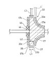
図1のトロイダル型無段変速機の要部を示す縦断面図である。
図1のトロイダル型無段変速機のディスクシュラウドおよびローラシュラウドを示す斜視図である。
図1のトロイダル型無段変速機を示す平面図である。
図2のトロイダル型無段変速機の変形例を示す模式図である。
図2のトロイダル型無段変速機の他の変形例を示す模式図である。
本発明の効果を説明するための図であり、(a)はディスクシュラウドを設けない場合のオイルの流れを示す部分的な横断面図、(b)はディスクシュラウドを設けた場合のオイルの流れを示す部分的な横断面図である。
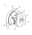
本発明の第2実施形態に係るトロイダル型無段変速機を示す斜視図である。
以下,本発明の好ましい実施形態を図面に基づいて説明する。図1は本発明の第1実施形態に係るトロイダル型無段変速機(以下、単に「無段変速機」と呼ぶ。)1を模式的に示す縦断面図である。無段変速機1は、航空機エンジンEと、この航空機エンジンEによって駆動される一定周波数発電装置Gとの間に介在して、発電装置Eの回転数を一定に保ちながら航空機エンジンEの駆動力を一定周波数発電装置Gへ伝達する。
航空機エンジンEは、動力伝達機構T、変速機構Rを介して、無段変速機1の変速機入力軸3に接続されている。変速機入力軸3に入力された動力は、無段変速機1を介して、変速機入力軸3の中空部に同心に配置された変速機出力軸5から、発電装置Gへ出力される。
同図に示すように、無段変速機1は、ダブルキャビティ型トロイダルトラクションドライブとして構成されており、変速機入力軸3に沿って第1キャビティ11および第2キャビティ13を所定の間隔を設けて配設してなる。第1キャビティ11と第2キャビティ13の間に、変速機構Rの構成部品であるギヤや軸受などが配置されている。
第1キャビティ11,第2キャビティ13は、変速機入力軸3と連動して回転する入力ディスク15と、変速機出力軸5と連動して回転する出力ディスク17と、入力ディスク15および出力ディスク17の間に介在する複数(例えば2つ)のパワーローラ19によって構成されている。両キャビティ11,13の軸方向内側に入力ディスク15が配設され、両キャビティ11,13の軸方向外側に出力ディスク17が配設されている。
第1キャビティ11を形成する1対の入力ディスク15と出力ディスク17とは、同心状に対向して配置されている。同様に、第2キャビティ13を形成する他の1対の入力ディスク15と出力ディスク17とは、同心状に対向して配置されている。2つの入力ディスク15,15は、変速機入力軸3を介して連結されている。本実施形態では、第1キャビティ11と第2キャビティ13とは同様の構造を有しているので、以下、代表として第1キャビティ11の構造について説明する。
各パワーローラ19は、スラスト軸受21と、支持部材であるトラニオン23とによって、ローラ軸25回りの回転を許容し、かつローラ軸25および変速機入力軸3を含む平面内で傾転自在に支持されている。このように支持されたパワーローラ19が、入力ディスク15の凹曲面状の内側壁15aおよび出力ディスク17の凹曲面状の内側面17aに、パワーローラ19の押付力を発生させる押圧力付加機構(図示せず)の動力により高圧で押し付けられている。
すなわち、この押圧力付加機構は、入力ディスク15と出力ディスク17に互いに接近するように軸方向押圧力を付加するディスク軸力付加部と、パワーローラ19を両ディスク15,17に押し当てるローラ押圧力付加部とを含み、キャビティ11において、入力ディスク15、出力ディスク17およびパワーローラ19という3つの転動体を、高圧で互いに押し付けている。両ディスク15,17とパワーローラ19との接触部に生じる高粘度潤滑油膜の剪断抵抗、つまり流体摩擦によって、3つの部材入力ディスク15、出力ディスク17およびパワーローラ19間で駆動力が伝達される。無段変速機1の加速比および減速比、すなわち変速比の変更は、パワーローラ19の傾きである傾転角を制御することにより行われる。
無段変速機1には、入力ディスク15を覆う入力側ディスクシュラウド31と、出力ディスク17を覆う出力側ディスクシュラウド33が設けられている。また、各パワーローラ19は、ローラシュラウド35によって覆われている。以下、代表して、主に出力側ディスクシュラウド33の構成について説明するが、入力側ディスクシュラウド31も出力側ディスクシュラウド33と同様に構成されている。
図2に示すように、出力ディスク17は、前記内側面17a、外周面17b、および内側面17aの軸方向反対側を向くほぼ平坦な外側面17cを有している。出力側ディスクシュラウド33は、出力ディスク17の内側面17aを隙間を介して覆う内側壁33a、外周面17bを隙間を介して覆う外周壁33b、および外側面17cを隙間を介して覆う外側壁33cを有している。出力側ディスクシュラウド33の内側壁33aは、出力ディスク17の内側面17aの形状に沿った凹曲面状に形成され、外周壁33bは、出力ディスク17の外周面17bの形状に沿った円筒状に形成され、外側壁33cは、出力ディスク17の径方向に沿った円盤状に形成されている。
出力側ディスクシュラウド33には、このディスクシュラウド33の内面から外面に貫通し、周方向に延びるオイル排出溝が形成されている。具体的には、本実施形態では、出力側ディスクシュラウド33の内側壁33aと外周壁33bとの間の隙間が、出力側ディスクシュラウド33の内面から外面に貫通し、全周に渡って延びる内側オイル排出溝37を形成している。また、出力側ディスクシュラウド33の外側壁33cと外周壁33bとの間の隙間が、ディスクシュラウドの内面から外面に貫通し、全周に渡って延びる外側オイル排出溝39を形成している。換言すれば、内側オイル排出溝37は、出力側ディスクシュラウド33の内側壁33aの外周部に、外周部の全周に渡って設けられており、外側オイル排出溝39は、ディスクシュラウドの外側壁33cの外周部に、外周部の全周に渡って設けられている。
なお、本明細書において、出力側ディスクシュラウド33の「外周部」とは、出力ディスク17の外周面17bを覆う外周壁33b、または内側壁33aもしくは外側壁33cの外周壁33bに隣接する部分を指す。
本実施形態では、上述のように、内側オイル排出溝37および外側オイル排出溝39を出力側ディスクシュラウド33の外周部の全周に渡って設けているので、出力側ディスクシュラウド33の内側壁33a、外周壁33bおよび外側壁33cは、それぞれ別体に形成されている。内側壁33aは無段変速機1が設置されるハウジング(図示せず)の天井面に固定された支柱41に支持されている。外周壁33bは無段変速機1が設置されるハウジング(図示せず)の天井面に固定された他の支柱43に支持されている。外側壁33cは、変速機出力軸5を支持する軸受44の軸受ハウジング45に支持されている。もっとも、内側壁33a,外周壁33b,外側壁33cの支持構造はこれらに限定されない。
出力側ディスクシュラウド33の内側壁33aには、図3に示すように、出力側ディスクシュラウド33と、ローラシュラウド35およびパワーローラ19との干渉を避けるためのローラ用切欠き47が形成されている。さらに、出力側ディスクシュラウド33の内側壁33aには、ディスクシュラウドの外部に設けられたオイル噴射器60(図7(b))から供給される冷却用オイルをディスクシュラウド33内に導入するための導入口51が形成されている。
図7(b)に示すように、オイル噴射器60は、出力側ディスクシュラウド33の内側壁33aに形成された導入口51を介して、出力側ディスクシュラウド33内の出力ディスク17の内側面17aへ、冷却用のオイル64を供給する。オイル噴射器60の配置は任意であるが、好ましくは、オイル噴射器60は、出力ディスク17の内側面17aに向けて内側面17aと直交する方向にオイル64を噴射するように配置される。オイル噴射器60をこのように配置して冷却用のオイル64を噴射することにより、出力ディスク17を効果的にインピンジ冷却することができる。
ローラシュラウド35は、図1のパワーローラ19の主としてスラスト軸受21の潤滑および冷却に用いられたオイルが入力ディスク15または出力ディスク17の周辺へ流入することを防止するために設けられる。より具体的には、パワーローラ19に供給されたオイルは、その大部分がスラスト軸受21の軸受空間(スラスト軸受21の軌道輪を形成するパワーローラ19とトラニオン23との間の空間)から排出される。したがって、本実施形態では、スラスト軸受21の軸受空間を覆うようにローラシュラウド35が配置されている。また、パワーローラ19において、入力ディスク15および出力ディスク17のうち、より高速で回転する側のディスク、すなわち本実施形態では入力ディスク15側の方が、オイル撹拌抵抗を低減する必要性が高い。したがって、ローラシュラウド35は、パワーローラ19の、少なくとも、より高速で回転するディスク側の部分を覆っていることが好ましい。本実施形態では、ローラシュラウド35は、図4に示すように、パワーローラ19の入力ディスク15側の部分を覆っている。出力ディスク17が入力ディスク15よりも高速で回転する場合には、ローラシュラウド35が、パワーローラ19の出力ディスク17側の部分を覆うように構成する。上記の各構成によれば、ローラシュラウド35のサイズおよび重量を抑制しつつ、効果的にオイルの流出を防止できる。
入力ディスク15におけるパワーローラ19と当接する部分の近傍においては、パワーローラ19およびローラシュラウド35によって、オイルが入力ディスク15の周囲に侵入することを防止する。したがって、図3の出力側ディスクシュラウド33に形成するローラ用切欠き47とローラシュラウド35との隙間からオイルがディスクシュラウド内に侵入することを防止するために、ローラシュラウド35とローラ用切欠き47との隙間は、パワーローラ19の傾転を妨げない限度で、できるだけ小さく設定することが好ましい。特には、ディスクによるオイルの撹拌損失が大きくなる高速回転時において、ローラ用切欠き47とローラシュラウド35との隙間を小さく設定することが好ましい。そのため、パワーローラ19が最も高速側に位置する場合のローラシュラウド35とローラ用切欠き47の外縁との隙間Sが、2mm以下となるように設定されている。なお、パワーローラ19をローラシュラウド35で覆わない場合は、パワーローラ19とローラ用切欠き47の外縁との隙間を上記のように設定する。
なお、本実施形態では、ディスクシュラウド33の外周部に、内側オイル排出溝37と外側オイル排出溝39を設けたが、いずれか一方のオイル排出溝を省略してもよい。また、ディスクシュラウド33内のオイルを効率的に排出するために、両オイル排出溝37,39は、本実施形態のように、ディスクシュラウド33の外周部の全周に渡って設けることが好ましい。これにより、ディスクシュラウド33の外周部に達したディスクシュラウド内のオイルを最短経路で外部へ排出することができる。
もっとも、図5の変形例に示すように、オイル排出溝37,39の一方または両方(図示の例では内側オイル排出溝37)は、少なくとも全周の1/8以上の周方向範囲、すなわちディスクの中心Oに対する開角度θが45°以上の範囲に設けられていれば、オイル撹拌抵抗を十分に低下させることができる。オイル排出溝を設ける周方向範囲を全周未満とした場合は、ディスクシュラウド33を構成する内側壁33a、外周壁33bおよび外側壁33cを一体的に形成することが可能となり、ディスクシュラウド33の支持機構の一部を省略することができる。
また、オイル排出溝37,39を設ける周方向範囲を全周未満とする場合は、オイル排出溝37,39が、少なくともディスクの回転方向Rにおける導入口51よりも下流側の周方向位置に設けられていることが好ましい。オイル排出溝37,39をこのように配置することにより、冷却用のオイル噴射器60から導入口51を介してディスクシュラウド33内に噴射された冷却用オイルを、効率的に外部へ排出することができる。
さらに、図2に示す例では、出力側ディスクシュラウド33の外周壁33bの軸方向長さL1は、出力ディスク17の外周面17bの軸方向長さL2とほぼ同一であり、かつ外周壁33bの軸方向位置が外周面17bの軸方向位置にほぼ一致するように構成されている。しかし、図6の変形例に示すように、出力側ディスクシュラウド33の外周壁33bの軸方向長さL1を出力ディスク17の外周面17bの軸方向長さL2よりも短く設定してもよい。このように構成することにより、図6の例における内側オイル排出溝37および外側オイル排出溝39の少なくとも一方の軸方向の開口面積を、図2の例に比べて大きく設定することができる。
好ましくは、図6に示すように、出力側ディスクシュラウド33の外周壁33bの、内側面17a側の部分を軸方向に短く設定することが好ましい。その場合の外周壁33bの軸方向長さL1は、出力ディスク17の外周面17bの軸方向長さL2に対して1/3~2/3の範囲にあることが好ましく、外周面17bの軸方向長さL2の1/2であることがより好ましい。このように構成することにより、内側オイル排出溝37の軸方向の開口面積を大きくすることができる。したがって、出力側ディスクシュラウド33の内側壁33aの内側に大量のオイルが流入した場合でも、そのオイルを極めて効果的に外部へ排出することができる。
このように、本実施形態に係る無段変速機1によれば、図1の入力ディスク15および出力ディスク17をディスクシュラウド31,33で覆うことによって、両ディスク15,17の周辺に存在する余分なオイルがディスク15,17の表面に接触することを防止できる。しかも、ディスクシュラウド31,33の外周部にオイルの排出溝37,39を設けたことにより、遠心力を利用して、排出溝37,39からのオイルの再進入を防止しつつ、ディスクシュラウド内のオイルをきわめて効率的に外部へ排出することができる。したがって、ディスク15,17周辺のオイル撹拌抵抗が大幅に低減されるとともに、オイルの回収および再利用が容易となる。特に、本実施形態では、オイルが、ディスクシュラウド31,33の内側壁31a,33aに形成された各導入口51を介して、各ディスク15,17の内側面15a,17aへ供給されるので、ディスクの遠心力をより効果的に利用してディスクシュラウド内のオイルを外部へ排出することができる。
上記ディスクシュラウド31,33の効果を、図7(a),(b)を参照しながら、出力側ディスクシュラウド33を代表として、より詳しく説明する。出力側ディスクシュラウド33を設けない場合、図7(a)に示すように、周辺の余分なオイル62が出力ディスク17の内側面17aに接触するのに加えて、インピンジ冷却効果を高めるためにオイル噴射器60から出力ディスク17の内側面17aに向けて内側面17aと直交する方向に噴射されたオイル64は、出力ディスク17の内側面17aに当たってはね返り、出力ディスク17の回転方向Rの上流側にも一部64aが流れ込むことで、オイル64の流れに乱れを発生させる。これにより、撹拌抵抗が増大する。これに対し、図7(b)に示すように、出力側ディスクシュラウド33を設けた場合、周辺の余分なオイル62が出力ディスク17に接触するのが防止される一方で、出力ディスク17の内側面17aと出力側ディスクシュラウド33との間に、回転方向Rと同一方向の強い空気流れAが形成される。この空気流れAがオイル64を回転方向Rに押し流すことによって、オイル64の一部64a(図7(a))が上流側に流れ込むことを防ぐ。これにより、オイル64の流れの乱れを抑制して撹拌抵抗を低減させる。
次に、図8に示す本発明の第2実施形態について説明する。第2実施形態に係る無段変速機1では、第1実施形態の構成に追加して、入力側および出力側ディスクシュラウド31,33の外周部に、入力および出力ディスク15,17の接線方向Tに開口するオイル排出口61を設けている。
本実施形態では、入力側ディスクシュラウド31と出力側ディスクシュラウド33のいずれにもオイル排出口61を設けたが、いずれか一方にのみオイル排出口61を設けてもよい。また、各ディスクシュラウド31,33において、それぞれ周方向にほぼ180°離間した2箇所にオイル排出口61を設けたが、各ディスクシュラウド31,33におけるオイル排出口61の数および位置は、図示の例に限らず、適宜設定してよい。
このように、ディスクシュラウド31,33の外周部に、ディスクの接線方向Tに開口するオイル排出口61を設けた場合には、ディスクの冷却のためにディスクに供給されたオイルを一層効率的に排出し、回収することが可能となる。
なお、上記の各実施形態の説明においては、航空機用のIDGに使用するトロイダル型無段変速機を例として示したが、本発明が適用されるトロイダル型無段変速機の用途は航空機に限られず、例えば、自動車用であってもよい。また、本発明は、ダブルキャビティ型に限らず、入力ディスクおよび出力ディスクを1対のみ設けたシングルキャビティ型のトロイダル型無段変速機にも適用することができる。
以上のとおり、図面を参照しながら本発明の好適な実施形態を説明したが、本発明の趣旨を逸脱しない範囲内で、種々の追加、変更または削除が可能である。したがって、そのようなものも本発明の範囲内に含まれる。
1 タービン動翼(タービン翼)
5 第1冷却媒体通路(冷却媒体通路)
15 入力ディスク
17 出力ディスク
19 パワーローラ
31 入力側ディスクシュラウド
33 出力側ディスクシュラウド
33a 出力側ディスクシュラウドの内側壁
33b 出力側ディスクシュラウドの外周壁
33c 出力側ディスクシュラウドの外側壁
37,39 オイル排出溝
61 オイル排出口
5 第1冷却媒体通路(冷却媒体通路)
15 入力ディスク
17 出力ディスク
19 パワーローラ
31 入力側ディスクシュラウド
33 出力側ディスクシュラウド
33a 出力側ディスクシュラウドの内側壁
33b 出力側ディスクシュラウドの外周壁
33c 出力側ディスクシュラウドの外側壁
37,39 オイル排出溝
61 オイル排出口
Claims (12)
- 少なくとも1対の入力ディスクおよび出力ディスクと、
前記1対の入力ディスクと出力ディスクとの間に傾転可能に介在して、前記入力ディスクから前記出力ディスクへ駆動力を伝達するパワーローラと、
前記入力ディスクおよび出力ディスクをそれぞれ覆うディスクシュラウドと、
を備え、
前記ディスクシュラウドの外周部に、このディスクシュラウドの内面から外面に貫通し、周方向に延びる、前記ディスクシュラウド内部のオイルを外部へ排出するオイル排出溝が形成されているトロイダル型無段変速機。 - 請求項1に記載のトロイダル型無段変速機において、前記オイル排出溝は、前記入力ディスクおよび出力ディスクの前記パワーローラが押し付けられる各内側面に供給されたオイルを前記ディスクシュラウドの外部へ排出するトロイダル型無段変速機。
- 請求項1または2に記載のトロイダル型無段変速機において、前記オイル排出溝は、前記ディスクシュラウドの内側壁の外周部に設けられているトロイダル型無段変速機。
- 請求項1から3のいずれか一項に記載のトロイダル型無段変速機において、前記オイル排出溝は、前記ディスクシュラウドの外側壁の外周部に設けられているトロイダル型無段変速機。
- 請求項3または4において、前記入力ディスクまたは出力ディスクの外周面を覆う前記ディスクシュラウドの外周壁の軸方向長さが、当該入力ディスクまたは出力ディスクの外周面の軸方向長さよりも短く設定されており、前記オイル排出溝が、前記内側壁と前記外周壁との間の隙間、または前記外側壁と前記外周壁との間の隙間として形成されているトロイダル型無段変速機。
- 請求項1から5のいずれか一項に記載のトロイダル型無段変速機において、前記ディスクシュラウドの内側壁に、該ディスクシュラウドの外部からの冷却用オイルをディスクシュラウド内に導入するための導入口が設けられており、前記オイル排出溝が、少なくとも前記ディスクの回転方向における前記導入口よりも下流側の周方向位置に配置されているトロイダル型無段変速機。
- 請求項1から6のいずれか一項に記載のトロイダル型無段変速機において、前記オイル排出溝が、前記ディスクシュラウドの外周部の全周の1/8以上の周方向部分に設けられているトロイダル型無段変速機。
- 請求項7に記載のトロイダル型無段変速機において、前記オイル排出溝が、前記ディスクシュラウドの外周部の全周に渡って設けられているトロイダル型無段変速機。
- 請求項1から8のいずれか一項に記載のトロイダル型無段変速機において、さらに、前記パワーローラを覆うローラシュラウドを有するトロイダル型無段変速機。
- 請求項9に記載のトロイダル型無段変速機において、前記ローラシュラウドは、前記パワーローラの、少なくとも、前記入力ディスクおよび前記出力ディスクのうち、より高速で回転するディスク側の部分を覆っているトロイダル型無段変速機。
- 請求項9または10に記載のトロイダル型無段変速機において、前記ローラシュラウドは、前記パワーローラの軸受空間を覆っているトロイダル型無段変速機。
- 請求項1から11のいずれか一項に記載のトロイダル型無段変速機において、前記ディスクシュラウドの外周部に、前記ディスクの接線方向に開口するオイル排出口が設けられているトロイダル型無段変速機。
Priority Applications (4)
| Application Number | Priority Date | Filing Date | Title |
|---|---|---|---|
| EP14816646.5A EP3015739B1 (en) | 2013-06-26 | 2014-06-20 | Toroidal-type stepless transmission |
| CA2916049A CA2916049C (en) | 2013-06-26 | 2014-06-20 | Toroidal-type stepless transmission |
| CN201480035912.0A CN105324592A (zh) | 2013-06-26 | 2014-06-20 | 环型无级变速器 |
| US14/973,874 US10415690B2 (en) | 2013-06-26 | 2015-12-18 | Toroidal-type stepless transmission |
Applications Claiming Priority (2)
| Application Number | Priority Date | Filing Date | Title |
|---|---|---|---|
| JP2013133476A JP5755689B2 (ja) | 2013-06-26 | 2013-06-26 | トロイダル型無段変速機 |
| JP2013-133476 | 2013-06-26 |
Related Child Applications (1)
| Application Number | Title | Priority Date | Filing Date |
|---|---|---|---|
| US14/973,874 Continuation US10415690B2 (en) | 2013-06-26 | 2015-12-18 | Toroidal-type stepless transmission |
Publications (1)
| Publication Number | Publication Date |
|---|---|
| WO2014208457A1 true WO2014208457A1 (ja) | 2014-12-31 |
Family
ID=52141797
Family Applications (1)
| Application Number | Title | Priority Date | Filing Date |
|---|---|---|---|
| PCT/JP2014/066387 WO2014208457A1 (ja) | 2013-06-26 | 2014-06-20 | トロイダル型無段変速機 |
Country Status (6)
| Country | Link |
|---|---|
| US (1) | US10415690B2 (ja) |
| EP (1) | EP3015739B1 (ja) |
| JP (1) | JP5755689B2 (ja) |
| CN (1) | CN105324592A (ja) |
| CA (1) | CA2916049C (ja) |
| WO (1) | WO2014208457A1 (ja) |
Families Citing this family (5)
| Publication number | Priority date | Publication date | Assignee | Title |
|---|---|---|---|---|
| JP6359319B2 (ja) * | 2014-04-14 | 2018-07-18 | 川崎重工業株式会社 | トロイダル型無段変速機 |
| JP6554294B2 (ja) * | 2015-03-09 | 2019-07-31 | 川崎重工業株式会社 | トロイダル無段変速機及び航空機用駆動機構一体型発電装置 |
| JP6505477B2 (ja) * | 2015-03-13 | 2019-04-24 | 川崎重工業株式会社 | 変速装置及びそれを備える発電システム |
| EP3390866B1 (en) * | 2015-12-10 | 2022-07-20 | Transmission CVT Corp Inc. | Roller cooling arrangement for toroidal cvt |
| JP2022099667A (ja) * | 2020-12-23 | 2022-07-05 | 川崎重工業株式会社 | トロイダル無段変速機 |
Citations (6)
| Publication number | Priority date | Publication date | Assignee | Title |
|---|---|---|---|---|
| JPH11280876A (ja) * | 1998-03-27 | 1999-10-15 | Isuzu Motors Ltd | トロイダル型無段変速機の潤滑装置 |
| JP2006503230A (ja) * | 2002-01-24 | 2006-01-26 | トロトラック・(ディベロップメント)・リミテッド | ローリングトラクション連続可変速比動力伝達ユニットのための流体供給装置 |
| JP2008032084A (ja) * | 2006-07-27 | 2008-02-14 | Nsk Ltd | トロイダル型無段変速機 |
| JP2008039088A (ja) * | 2006-08-07 | 2008-02-21 | Toyota Motor Corp | トロイダル式無段変速機 |
| JP2008038902A (ja) | 2006-07-12 | 2008-02-21 | Kawasaki Heavy Ind Ltd | トラクション変速機構付き発電・スタータ装置 |
| JP2009192080A (ja) * | 2008-01-18 | 2009-08-27 | Nsk Ltd | トロイダル型無段変速機 |
Family Cites Families (7)
| Publication number | Priority date | Publication date | Assignee | Title |
|---|---|---|---|---|
| JP3400009B2 (ja) * | 1993-03-24 | 2003-04-28 | マツダ株式会社 | トロイダル型無段変速機 |
| JPH11336868A (ja) * | 1998-05-21 | 1999-12-07 | Nissan Motor Co Ltd | トロイダル型無段変速機 |
| JP3624367B2 (ja) * | 1999-12-09 | 2005-03-02 | 日産自動車株式会社 | トロイダル型無段変速機 |
| JP3565169B2 (ja) * | 2001-01-19 | 2004-09-15 | トヨタ自動車株式会社 | トロイダル型無段変速機 |
| DE10244824A1 (de) * | 2002-09-26 | 2004-04-08 | Bayerische Motoren Werke Ag | Toroidgetriebe mit an den Zwischenrollen angeordneten Ölsammeleinrichtungen |
| JP4702600B2 (ja) * | 2005-03-22 | 2011-06-15 | 株式会社ジェイテクト | トロイダル型無段変速機 |
| JP4539765B2 (ja) | 2008-08-08 | 2010-09-08 | トヨタ自動車株式会社 | トロイダル式無段変速機 |
-
2013
- 2013-06-26 JP JP2013133476A patent/JP5755689B2/ja active Active
-
2014
- 2014-06-20 EP EP14816646.5A patent/EP3015739B1/en active Active
- 2014-06-20 WO PCT/JP2014/066387 patent/WO2014208457A1/ja active Application Filing
- 2014-06-20 CN CN201480035912.0A patent/CN105324592A/zh active Pending
- 2014-06-20 CA CA2916049A patent/CA2916049C/en active Active
-
2015
- 2015-12-18 US US14/973,874 patent/US10415690B2/en active Active
Patent Citations (6)
| Publication number | Priority date | Publication date | Assignee | Title |
|---|---|---|---|---|
| JPH11280876A (ja) * | 1998-03-27 | 1999-10-15 | Isuzu Motors Ltd | トロイダル型無段変速機の潤滑装置 |
| JP2006503230A (ja) * | 2002-01-24 | 2006-01-26 | トロトラック・(ディベロップメント)・リミテッド | ローリングトラクション連続可変速比動力伝達ユニットのための流体供給装置 |
| JP2008038902A (ja) | 2006-07-12 | 2008-02-21 | Kawasaki Heavy Ind Ltd | トラクション変速機構付き発電・スタータ装置 |
| JP2008032084A (ja) * | 2006-07-27 | 2008-02-14 | Nsk Ltd | トロイダル型無段変速機 |
| JP2008039088A (ja) * | 2006-08-07 | 2008-02-21 | Toyota Motor Corp | トロイダル式無段変速機 |
| JP2009192080A (ja) * | 2008-01-18 | 2009-08-27 | Nsk Ltd | トロイダル型無段変速機 |
Non-Patent Citations (1)
| Title |
|---|
| See also references of EP3015739A4 |
Also Published As
| Publication number | Publication date |
|---|---|
| EP3015739B1 (en) | 2019-05-01 |
| CA2916049C (en) | 2017-04-04 |
| JP5755689B2 (ja) | 2015-07-29 |
| US10415690B2 (en) | 2019-09-17 |
| CN105324592A (zh) | 2016-02-10 |
| JP2015007464A (ja) | 2015-01-15 |
| CA2916049A1 (en) | 2014-12-31 |
| EP3015739A1 (en) | 2016-05-04 |
| EP3015739A4 (en) | 2017-12-13 |
| US20160102750A1 (en) | 2016-04-14 |
Similar Documents
| Publication | Publication Date | Title |
|---|---|---|
| WO2014208457A1 (ja) | トロイダル型無段変速機 | |
| JP5720781B2 (ja) | 無段変速機 | |
| JP6113201B2 (ja) | 転がり軸受装置及びその使用 | |
| JP2007321931A (ja) | トロイダル型無段変速機 | |
| JP6774557B2 (ja) | トロイダル無段変速機用押圧装置 | |
| JP6168739B2 (ja) | ターボチャージャ用軸受装置 | |
| KR101489749B1 (ko) | 축추력 제거 장치 | |
| JP2765487B2 (ja) | デファレンシャル用軸受の潤滑装置 | |
| US10570999B2 (en) | Toroidal continuously variable transmission | |
| JP5829397B2 (ja) | ターボチャージャの回転軸の軸受方法及び装置 | |
| JP4962350B2 (ja) | トロイダル型無段変速機 | |
| JP4702600B2 (ja) | トロイダル型無段変速機 | |
| JP6411921B2 (ja) | ディファレンシャルギヤの潤滑構造 | |
| JPS63270916A (ja) | 転がり軸受 | |
| WO2020017136A1 (ja) | 過給機 | |
| US11940008B2 (en) | Recirculation of lubricant in a turbomachine rolling-element bearing | |
| JP2007107625A (ja) | トロイダル型無段変速機 | |
| JP2009002489A (ja) | トロイダル型無段変速機 | |
| JP2006132727A (ja) | トロイダル型無段変速機 | |
| JP2015227687A (ja) | 摩擦ローラ式変速機 | |
| JP2008038751A (ja) | 風力発電機用増速機 | |
| JP2005069394A (ja) | トロイダル型無段変速機 | |
| JP2008281151A (ja) | トロイダル型無段変速機 | |
| JP2005155687A (ja) | シングルキャビティ式トロイダル型無段変速機 | |
| JP2007057032A (ja) | 無段変速装置 |
Legal Events
| Date | Code | Title | Description |
|---|---|---|---|
| WWE | Wipo information: entry into national phase |
Ref document number: 201480035912.0 Country of ref document: CN |
|
| 121 | Ep: the epo has been informed by wipo that ep was designated in this application |
Ref document number: 14816646 Country of ref document: EP Kind code of ref document: A1 |
|
| ENP | Entry into the national phase |
Ref document number: 2916049 Country of ref document: CA |
|
| NENP | Non-entry into the national phase |
Ref country code: DE |
|
| WWE | Wipo information: entry into national phase |
Ref document number: 2014816646 Country of ref document: EP |