WO2014208372A1 - 溶接方法及び溶接装置 - Google Patents
溶接方法及び溶接装置 Download PDFInfo
- Publication number
- WO2014208372A1 WO2014208372A1 PCT/JP2014/065805 JP2014065805W WO2014208372A1 WO 2014208372 A1 WO2014208372 A1 WO 2014208372A1 JP 2014065805 W JP2014065805 W JP 2014065805W WO 2014208372 A1 WO2014208372 A1 WO 2014208372A1
- Authority
- WO
- WIPO (PCT)
- Prior art keywords
- welding
- main
- base material
- steering member
- component
- Prior art date
Links
Images


Classifications
-
- B—PERFORMING OPERATIONS; TRANSPORTING
- B23—MACHINE TOOLS; METAL-WORKING NOT OTHERWISE PROVIDED FOR
- B23K—SOLDERING OR UNSOLDERING; WELDING; CLADDING OR PLATING BY SOLDERING OR WELDING; CUTTING BY APPLYING HEAT LOCALLY, e.g. FLAME CUTTING; WORKING BY LASER BEAM
- B23K9/00—Arc welding or cutting
- B23K9/12—Automatic feeding or moving of electrodes or work for spot or seam welding or cutting
-
- B—PERFORMING OPERATIONS; TRANSPORTING
- B23—MACHINE TOOLS; METAL-WORKING NOT OTHERWISE PROVIDED FOR
- B23K—SOLDERING OR UNSOLDERING; WELDING; CLADDING OR PLATING BY SOLDERING OR WELDING; CUTTING BY APPLYING HEAT LOCALLY, e.g. FLAME CUTTING; WORKING BY LASER BEAM
- B23K37/00—Auxiliary devices or processes, not specially adapted to a procedure covered by only one of the preceding main groups
- B23K37/02—Carriages for supporting the welding or cutting element
- B23K37/0247—Driving means
-
- B—PERFORMING OPERATIONS; TRANSPORTING
- B23—MACHINE TOOLS; METAL-WORKING NOT OTHERWISE PROVIDED FOR
- B23K—SOLDERING OR UNSOLDERING; WELDING; CLADDING OR PLATING BY SOLDERING OR WELDING; CUTTING BY APPLYING HEAT LOCALLY, e.g. FLAME CUTTING; WORKING BY LASER BEAM
- B23K37/00—Auxiliary devices or processes, not specially adapted to a procedure covered by only one of the preceding main groups
- B23K37/04—Auxiliary devices or processes, not specially adapted to a procedure covered by only one of the preceding main groups for holding or positioning work
- B23K37/0426—Fixtures for other work
- B23K37/0435—Clamps
-
- B—PERFORMING OPERATIONS; TRANSPORTING
- B25—HAND TOOLS; PORTABLE POWER-DRIVEN TOOLS; MANIPULATORS
- B25J—MANIPULATORS; CHAMBERS PROVIDED WITH MANIPULATION DEVICES
- B25J9/00—Programme-controlled manipulators
- B25J9/16—Programme controls
- B25J9/1679—Programme controls characterised by the tasks executed
- B25J9/1682—Dual arm manipulator; Coordination of several manipulators
Definitions
- the present invention relates to a welding method and a welding apparatus.
- Automobiles are manufactured by joining and assembling tens of thousands of parts by bolting, bonding, or welding.
- a steering member for example, a pipe-like long member constituting the steering member and several types of parts such as a steering column and an audio bracket are each gripped by a robot hand and welded by a welding device (Patent Document) 1).
- the bracket and the long member cannot be sufficiently fixed only by performing pinpoint welding at the contact portion between the bracket and the long member.
- the welded part must be formed to a certain length. For this reason, it takes a certain amount of time to weld the part, and the robot hand must hold the member to be welded until the welding is completed, so another operation cannot be performed, and the cycle time becomes longer, and the steering member becomes longer. There is a problem that the welding of this cannot be performed quickly.
- an object of the present invention is to provide a welding method and a welding apparatus that can quickly perform a welding operation of a steering member or the like using a robot hand.
- the second member is gripped and positioned with respect to the first member. Then, welding for temporarily fixing the second member to the first member is performed at the contact portion between the first member and the second member while the second member is held, thereby forming a temporarily-welded weld location. And the holding
- two or more main welding locations are formed along the direction of the force acting on the second member, and temporary fixing welding locations are formed between the respective main welding locations.
- the welding apparatus includes a gripping portion that can freely grip and release the second member, a welding portion that welds the second member to the first member, and operations of the gripping portion and the welding portion.
- the gripping portion and the welded portion are controlled so as to form a temporary welding location between the respective main welding locations.
- FIG. 3 is a perspective view showing a case where parts different from those in FIG. 2 are welded and two temporary fixing welds are provided. It is a perspective view which shows the time of applying the welding method which concerns on this invention to components different from FIG. It is a perspective view which shows the time of applying the welding method which concerns on this invention to components different from FIG. It is a perspective view which shows the time of applying the welding method which concerns on this invention to components different from FIG.
- FIG. 1 is a perspective view showing a welding apparatus according to an embodiment of the present invention
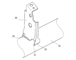
- FIG. 2 is an enlarged view showing the vicinity of a member to be welded in
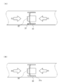
- FIG. 3A is a plan view showing the vicinity of the parts to be welded in FIG. 2 in the welding method according to the embodiment of the present invention
- FIG. 3B shows the proportionality of FIG. 3A. It is a top view.
- the welding apparatus 100 welds and joins a steering member base material 10 (corresponding to a first member) and a component 20 (corresponding to a second member). To do.
- the welding apparatus 100 performs welding for temporarily fixing the component 20 to the steering member base material 10 at the contact portion between the component 20 and the steering member base material 10 to temporarily fix the welding position 31 (see the black circle in FIG. 2.
- the main welding is performed at a position where the part 20 and the steering member base material 10 do not overlap with the temporarily fixed welding position 31, and the main welding positions 32 and 33 (see the two-dot chain line in FIG. 2; see FIGS. 3 to 7). The same applies to the above.
- the component 20 is gripped by the hand robot 110 (corresponding to the gripping portion) and positioned at a position where it is joined to the steering member base material 10.
- Joining to the steering member base material 10 is performed by a welding robot 120 (corresponding to a welded portion).
- the hand robot 110 and the welding robot 120 are multi-axis robots that perform predetermined operations based on previously taught data.
- the steering member base material 10 is supported by support jigs 181 and 182. In this embodiment, items for welding the steering member will be described. However, the present invention is not limited to the steering member. Details will be described below.
- the hand robot 110 has a hand 111 attached to its arm tip.
- the hand robot 110 grips a component in a predetermined direction by the hand 111 and positions the gripped component at a taught position with respect to the steering member base material 10.
- the parts are placed on the parts table 170, and the hand robot 110 grips the parts from the parts table 170 and positions them at a predetermined position on the steering member base material 10.
- the parts are carried into the parts table 170 by another robot (not shown) or a conveyor. Further, instead of the parts table 170, the hand robot 110 may grip the parts flowing by the transport conveyor.
- a first camera 140 that captures the direction of the tip of the hand 111 is attached.
- the first camera 140 is used for capturing the part and grasping the direction and size when the hand 111 takes out the part.
- the second camera 150 is installed within the work range of this process.
- the second camera 150 is used for confirming in what direction the component gripped by the hand 111 is gripped.
- the hand robot 110 operates to hold the component from the component table 170 and then hold the component toward the second camera 150.
- the second camera 150 captures the part gripped by the hand 111, and it is possible to confirm in what direction and position the part is gripped by the hand 111 by image processing.
- the hand robot 110 corrects the orientation of the component so that the component can be positioned on the steering member base material 10 from the orientation and position of the component confirmed by the second camera 150.
- the steering member base material 10 can be positioned at the component position taught with respect to the steering member base material 10. Since the operation of correcting the orientation of the component held by the hand 111 is a general operation of a hand robot, description thereof is omitted.
- the welding robot 120 has a welding torch 121 attached to the arm tip.
- the tip of the welding torch 121 is positioned at a position where the part can be welded with reference to the position of the part positioned on the steering member base material 10.
- the tip position of the welding torch 121 is also corrected.
- the welding robot 120 performs welding using the welding torch 121.
- welding may be performed by a laser injection device.
- a third camera 160 is attached in the vicinity of the root portion of the welding torch 121.
- the third camera 160 photographs the part positioned by the hand 111. Then, the position (and / or inclination) of the component is measured from the captured image. Therefore, the third camera 160 has a function of measuring the size of an object and the distance between objects in a captured image (referred to as an intra-image distance measurement function).
- an image distance measurement function for example, an object (reference scale) used as a reference for determining a distance in an image is photographed in advance, and the correspondence between the actual size of the reference scale and the size in the image is obtained. Keep it.
- Such an intra-image distance measuring function may be a well-known one and is not particularly limited.
- the third camera 160 may have a distance measuring function for measuring the distance from the current position of the third camera 160 to the photographed object.
- a distance measuring function for measuring the distance from the current position of the third camera 160 to the photographed object.
- the distance measuring function may be a well-known one and is not particularly limited. By using such a distance measuring function and an in-image distance measuring function, the part position measured by the third camera 160 can be calculated as the position in the operation coordinate system of the welding robot 120.
- control unit 130 performs image processing in distance measurement within an image, distance measurement performed as necessary, and calculation processing thereof.
- the supporting jigs 181 and 182 support the steering member base material 10 so as to freely rotate around the longitudinal direction while holding both ends of the steering member base material 10 so as not to move in the longitudinal direction.
- the support jigs 181 and 182 include clampers 191 and 192 that clamp the end portions of the steering member base material 10, respectively. Both ends of the steering member base material 10 are clamped by the clampers 191 and 192, and the steering member base material 10 is restrained from moving in the longitudinal direction.
- one support jig 181 is provided with a servomotor with an encoder (not shown) for rotating the clamper 191.
- the motor is equipped with a brake so that it will not rotate inadvertently except during motor operation.
- a rotation angle (amount of rotation) is obtained by feedback from the encoder.
- the clamper 192 of the other support jig 182 is rotatable.
- the steering member base material 10 When welding the bracket to the steering member base material 10, the steering member base material 10 is rotated, and the parts are positioned at the joining position by the hand robot 110 in a specific position, and are welded by the welding robot 120. Therefore, the steering member base material 10 and the side bracket that is first joined to the steering member base material 10 are provided with base material reference points that allow the rotational position of the steering member base material 10 to be known.
- the base material reference point may be a screw hole, a notch, or other mark shape or mark itself.
- the steering member base material 10 is a pipe-like member and is usually a steel pipe. As described above, in the process of joining the components to the steering member base material 10, the side brackets are first attached to both ends of the steering member base material 10, and thereafter, the clampers 191 and 192 hold and rotate the side brackets. Thus, the steering member base material 10 is rotated to the rotation position of the component to be attached next, and the component is carried to a predetermined position by the hand robot 110.
- the control unit 130 has a configuration such as a CPU, a memory, and an input / output interface. With the configuration, the control unit 130 controls the operation of the hand robot 110 and the welding robot 120 and the rotational position of the steering member base material 10 by the support jigs 181 and 182. Control is performed. In addition, the control unit 130 captures the first camera 140, corrects the position of the part gripped by the hand 111 from the image captured by the second camera 150, and sets the distance between objects from the image captured by the third camera 160. It also controls image processing for calculation.
- the control unit 130 may be configured by a single device and may control the support jigs 181 and 182, the hand robot 110, the welding robot 120, the first camera 140, the second camera 150, and the third camera 160. In addition, a device that performs control for each of the above configurations may be provided to perform data communication to control the welding operation.
- the hand robot 110 is previously taught an operation of recognizing and holding a part to be welded to the steering member base material 10 on the part table 170 and recognizing and correcting the position and orientation of the part 20 photographed by the second camera 150. ing. The hand robot 110 is also taught to grip the part 20 and position it at a predetermined position and receive a signal from the welding robot 120 to pick up the next part. This operation is repeated until there are no parts to be welded to the steering member base material 10.
- teaching data is programmed so that the welding torch 121 is moved to perform temporary welding or main welding at a predetermined position.
- the hand robot 110 positions the component 20 at the position taught by the control unit 130. And the welding torch 121 of the welding robot 120 approaches the taught part in the contact part of the steering member base material 10 and the component 20, and performs temporary fixing welding.
- a temporary fixing welding location 31 as shown in FIG. 2 is formed at the contact portion between the steering member base material 10 and the component 20.
- the steering member base material 10 and the component 20 are temporarily fixed and positioned by the temporary fixing weld location 31 until the main welding is performed. Therefore, the hand robot 110 can release the grip of the component 20 after the temporary fixing welding. Therefore, the hand robot 110 can perform operations such as picking up the next part while the welding robot 120 is performing the main welding, and the total amount of time until all the parts are welded to the steering member base material 10. As a result, the welding work time can be shortened.
- Temporary welding can be used as positioning welding because the welding time is shorter than that of main welding and the thermal distortion of the welded part is small. Note that the position of the temporarily welded portion, the weld bead, and the like may be confirmed by the third camera 160.
- the welding torch 121 of the welding robot 120 forms the main welding locations 32 and 33 at the contact portion between the steering member base material 10 and the component 20 based on the teaching data for the main welding.
- two main welding points are formed, but the number of main welding points is not limited to two and may be more than two or one.
- the temporary welding location and the main welding location are numbered according to the welding order (31 ⁇ 32 ⁇ 33 in FIG. 2), and the main welding location 33 is formed after the main welding location 32 is formed. However, it is not limited to this.
- the main welding points 32 and 33 are formed by the control unit 130 and the welding robot 120 so as not to overlap the already formed temporary fixing welding point 31 at the contact portion between the steering member base material 10 and the part. This is because, if the main welding location is overlapped with the temporary welding location, the weld bead at the temporary welding location will be re-melted, thereby making it impossible to position the component 20 on the steering member base material 10. .
- the main welding points 32 and 33 so as not to overlap with the temporary fixing welding point 31, the positioning function of the component 20 with respect to the steering member base material 10 is maintained, a jig for the component 20 is not used, After the temporary welding, the gripping by the hand robot 110 can be released and the welding operation can be performed.
- two or more main welding locations are formed along the direction of the external forces F1 and F2 acting on the component 20 (main welding locations 32 and 33).
- the temporary fixing weld location 31 is formed between the main weld location 32 and the main weld location 33.
- the directions of the external forces F1 and F2 substantially coincide with the longitudinal direction of the steering member base material 10.
- the temporary fixing weld location 31 should just be arrange
- the temporary fixing welded portion 31 is formed so as to be sandwiched between the main welded portions 32 and 33. Even when the external force F1 is loaded in 3 (A), the first welding location 33 receives the input first. Further, even when the external force F2 is applied, the external force F2 is applied to the main welding location 32, and the external force is not initially applied to the temporary welding location 31 where the joining force is relatively weak. Therefore, it is possible to prevent a situation in which breakage occurs from a temporarily welded spot having a relatively weak joining force and breaks to a main weld spot in a chained manner, thereby sufficiently countering external force.
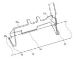
- FIG. 4 is a perspective view showing a case where the welding method according to the present embodiment is used for a part 20a (bracket airbag) different from the part 20 of FIG.
- the position, size, and number of temporary fixing welds are set in consideration of the fact that the part 20 can be temporarily positioned on the steering member base material 10, cracks due to hardening, and the location of the main welds are secured. Is done.
- one temporary fixing welding point 31 is provided.
- the main welding point 32 and the main welding are performed in the longitudinal direction of the steering member base material 10 by the control unit 130 and the welding robot 120.
- Temporary welding locations 31a may be formed between the locations 34
- temporary welding locations 31b may be formed between the main welding locations 33 and the main welding locations 34.
- the part can be positioned by adjusting the bead thickness or length, but the positioning function can be further enhanced by providing two or more locations.
- the positional relationship in the case where two temporary fixing welds are provided can be made symmetrical (180 ° positional relationship) when the contact portion between the steering member base material 10 and the component 20 is viewed in plan.
- the hand robot 110 grips the component 20 and positions it with respect to the steering member base material 10. Then, welding for temporarily fixing the component 20 to the steering member base material 10 is performed at a contact portion between the steering member base material 10 and the component 20 while the component 20 is held, thereby forming a temporary fixing weld location 31. Then, the gripping of the component 20 by the hand robot 110 is released. Then, the main welding is performed at a location other than the temporary welding location 31 at the contact location between the component 20 and the steering member base material 10 to form the main welding locations 32 and 33.
- the temporarily welded portion 31 is not remelted, and the positioning of the component 20 with respect to the steering member base material 10 is maintained by the temporarily welded portion 31. Therefore, the component 20 can be positioned on the steering member base material 10 without temporarily holding the component 20 by the hand robot 110 after the temporary fixing welding, and the hand robot 110 can perform another operation after the temporary fixing welding.
- Temporary fastening welding takes less time than main welding, so that it is possible to cause the hand robot 110 to perform another work after temporary fastening welding, so that the work of welding other parts to the steering member base material 10 can be performed faster. Thus, the operation of manufacturing the steering member can be performed quickly.
- the component 20 is held to the steering member base material 10 with a sufficient joining force until the main welding is performed. It is possible to sufficiently prevent a situation such as dropping from 10.
- main welding locations 32 and 33 are formed along the direction of the external forces F1 and F2 acting on the component 20 (the circumferential direction of the steering member base material 10 in this embodiment) (main welding locations 32 and 33).
- the temporary fixing weld location 31 is formed between the main weld location 32 and the main weld location 33.
- the external force is applied from the main welding location, and the external force is prevented from being first applied to the temporarily welded location. Therefore, it is possible to prevent a situation in which a temporarily welded part that tends to have a weaker bonding force than a main welded part is broken and chained to the main welded part, and the parts are fixed by temporary welding instead of a jig. Even when doing so, the strength of the welded part can be made sufficient. Further, by positioning the audio bracket or the like on the hand robot 110, the positioning operation can be quickly performed with stable accuracy.
- the welding apparatus 100 welds a component 20 corresponding to a second member such as a side bracket, a bracket airbag, an audio bracket, a bracket impact, and an instrument stay to the steering member base material 10 corresponding to the first member. Can be used for etc.
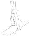
- FIGS. 5 to 7 are perspective views showing the welding method according to the present invention applied to parts different from those shown in FIGS. Note that the welding sequence is performed according to the sequence of the symbols as in FIGS.
- the present invention is not limited to this. Since the audio brackets are provided in pairs, a similar welding method may be used for the other audio bracket (component 20b) as shown in FIG.
- the temporary stay welded portion 31 is formed by the same welding method for the instrument stay (component 20c) shown in FIG. 6 and the bracket impact (component 20d) shown in FIG. , 33 (in addition to FIG. 7, the main welding point 34) may be formed.
- the embodiment has been described in which a plurality of parts such as an audio bracket and an instrument stay are welded to the steering member base material, the present invention is not limited to this.
- the welding method or the welding apparatus according to the present invention can be applied. That is, in a mass production line or the like, when welding for temporarily fixing a welded member to a welded member in one welded part is completed, the hand robot can be used for welding other welded parts, and the welding operation can be performed quickly.
- the embodiment has been described in which the component 20 is gripped by the hand robot 110 and the steering member base material 10 is supported by the support jigs 181 and 182, but the present invention is not limited thereto.
- the support jig used for the steering member base material 10 may be eliminated by gripping not only the component 20 but also the steering member base material 10 by a robot such as the hand robot 110.
- the present invention is not limited to this.
- the component 20 may be temporarily fixed by being positioned by an operator.
- Steering member base material (first member), 100 welding equipment, 110 hand robot (gripping part), 111 hands, 20 parts (second member, audio bracket), 20a parts (bracket airbag), 20b parts (the other audio bracket), 20c parts (instrument), 20d parts (bracket impact), 120 welding robot (welding part), 121 welding torch, 130 control unit, 31, 31a, 31b, 31x 32, 33, 34 welding locations, 140 the first camera, 150 Second camera, 160 Third camera, 170 parts table, 181 and 182 support jigs, 191, 192 Clamper, F1, F2 External force.
Abstract
【課題】ロボットハンドを用いたステアリングメンバ等の溶接作業を迅速に行うことができる溶接方法及び溶接装置を提供する。 【解決手段】本発明は、ステアリングメンバ母材10と部品20とを溶接によって接合するステアリングメンバの溶接方法において、ハンドロボット110によって部品を把持してステアリングメンバ母材に対して位置決めし、部品を把持したまま部品とステアリングメンバ母材との接触部位において部品を仮止めする溶接を行なって仮止め溶接箇所31を形成し、接触部位における仮止め溶接箇所以外の接触部位に本溶接を行って本溶接箇所32、33を形成し、本溶接箇所は第2部材に作用する力の方向に沿って形成され、各々の本溶接箇所の間に仮止め溶接箇所が形成される。
Description
本発明は溶接方法及び溶接装置に関する。
自動車は何万点にもおよぶ部品をボルト締結、接着、または溶接などによって接合し、組み立てることで製造される。ステアリングメンバの製造の際には、例えばステアリングメンバを構成するパイプ状の長尺部材とステアリングコラムやオーディオブラケット等の数種類の部品とがそれぞれロボットハンドによって把持され、溶接機器によって溶接される(特許文献1参照)。
上記ブラケット等をパイプ状の長尺部材に溶接するには、ブラケット等と長尺部材との接触部位にピンポイントで溶接を行うだけではブラケット等と長尺部材を十分に固定することができないため、溶接部位はある程度の長さ形成する必要がある。そのため、当該部位の溶接にはある程度時間がかかり、ロボットハンドは溶接が終わるまでは溶接する部材を保持しなければならないことから別の作業を行うことができず、サイクルタイムが長くなり、ステアリングメンバの溶接を迅速に行うことができない、という問題がある。
そこで本発明は上記課題を解決するためになされたものであり、ロボットハンドを用いたステアリングメンバ等の溶接作業を迅速に行うことができる溶接方法及び溶接装置を提供することを目的とする。
上記目的を達成する本発明に係る溶接方法は、第2部材を把持して第1部材に対して位置決めする。そして、第2部材を把持したまま第1部材と第2部材との接触部位において第2部材を第1部材に仮止めする溶接を行って仮止め溶接箇所を形成する。そして、第2部材の把持を解除し、仮止め溶接箇所以外の接触部位に本溶接を行って本溶接箇所を形成する。当該方法によって本溶接箇所は第2部材に作用する力の方向に沿って2箇所以上形成され、各々の本溶接箇所の間に仮止め溶接箇所が形成されることを特徴とする。
また、本発明に係る溶接装置は、第2部材の把持及び把持の解除が自在な把持部と、第1部材に対して第2部材を溶接する溶接部と、把持部及び溶接部の動作を制御する制御部と、を有する。制御部は、把持部によって第2部材を把持して第1部材に対して位置決めし、第2部材を把持したまま第1部材と第2部材との接触部位において溶接部によって第2部材を第1部材に仮止めする溶接を行って仮止め溶接箇所を形成するよう制御する。そして、把持部による第2部材の把持を解除し、溶接部によって仮止め溶接箇所以外の第1部材と第2部材との接触部位に本溶接を行って本溶接箇所を2箇所以上形成し、各々の本溶接箇所の間に仮止め溶接箇所を形成するように把持部及び溶接部を制御することを特徴とする。
以下、添付した図面を参照しながら、本発明の実施形態を説明する。なお、以下の記載は特許請求の範囲に記載される技術的範囲や用語の意義を限定するものではない。また、図面の寸法比率は説明の都合上誇張されており、実際の比率とは異なる場合がある。
図1は本発明の実施形態に係る溶接装置を示す斜視図、図2は図1において溶接される部材の付近を示す拡大図である。また、図3(A)は本発明の実施形態に係る溶接方法における、図2において溶接される部品付近を示す平面図であり、図3(B)は図3(A)の対比例を示す平面図である。
図1~3を参照して概説すれば、本実施形態に係る溶接装置100は、ステアリングメンバ母材10(第1部材に相当)と部品20(第2部材に相当)とを溶接して接合する。溶接装置100は、部品20とステアリングメンバ母材10との接触部位において部品20をステアリングメンバ母材10に仮止めするための溶接を行って仮止め溶接箇所31(図2の黒丸参照。図3~図7についても同様。)を形成する。次に、部品20とステアリングメンバ母材10との接触部位において仮止め溶接箇所31と重ならない箇所に本溶接を行って本溶接箇所32、33(図2の二点鎖線参照。図3~7についても同様。)を形成する。
溶接作業がスタートした時には、部品20はハンドロボット110(把持部に相当)によって把持されてステアリングメンバ母材10と接合する位置に位置決めされる。ステアリングメンバ母材10への接合は溶接ロボット120(溶接部に相当)によって行われる。ハンドロボット110及び溶接ロボット120は予め教示されたデータに基づいて所定の動作を行う多軸ロボットである。また、ステアリングメンバ母材10は支持治具181、182によって支持される。本実施形態ではステアリングメンバを溶接する事項について説明するが、本発明が適用されるものは、ステアリングメンバに限定されない。以下、詳述する。
ハンドロボット110は、そのアーム先端にハンド111が取り付けられている。ハンドロボット110は、ハンド111により所定の方向において部品を把持し、ステアリングメンバ母材10に対して、把持した部品を教示された位置に位置決めする。部品は部品テーブル170上に置かれていて、部品テーブル170からハンドロボット110が部品を把持してステアリングメンバ母材10上の所定位置に位置決めする。なお、部品テーブル170への部品の搬入は、図示しない他のロボットや搬送コンベアなどによって搬送されてくる。また、部品テーブル170に変えて、搬送コンベアによって流れてくる部品をハンドロボット110が把持するようにしてもよい。
ハンド111の近傍には、ハンド111の手先方向を撮影する第1カメラ140が取り付けられている。第1カメラ140は、ハンド111が部品を取り出す際に当該部品を撮影して向きや大きさを把握するために使用される。
また、この工程の作業範囲内には第2カメラ150が設置されている。第2カメラ150は、ハンド111によって把持された部品がどのような向きで把持されているかを確認するために使用される。
ハンドロボット110は、部品を部品テーブル170から把持した後、第2カメラ150に向かって部品をかざすように動作する。これによってハンド111に把持された部品を第2カメラ150が撮影して、画像処理により部品がハンド111にどのような向きや位置で把持されているかを確認できる。また、ハンドロボット110は、第2カメラ150によって確認された部品の向きや位置からステアリングメンバ母材10上に部品を位置決めできるように部品の向きを補正する。これにより、ステアリングメンバ母材10は、ステアリングメンバ母材10に対して教示された部品位置に位置決めすることができる。このようなハンド111によって把持された部品の向きなどを補正する動作は一般的なハンドロボットの動作であるので、説明は省略する。
溶接ロボット120は、アーム先端に溶接トーチ121が取り付けられている。溶接トーチ121の先端には、ステアリングメンバ母材10上に位置決めされた部品の位置を基準にして、その部品が溶接できる位置に位置決めされる。ハンドロボット110によって、ステアリングメンバ母材10に対する部品の位置が補正された場合には、溶接トーチ121の先端位置も補正される。なお、本実施形態では溶接ロボット120が溶接トーチ121を用いて溶接を行っているが、これに限定されず、例えば溶接トーチに代えてレーザー射出装置によって溶接を行ってもよい。
また、溶接トーチ121の根元部分近傍には第3カメラ160が取り付けられている。第3カメラ160は、ハンド111によって位置決めされている部品を撮影する。そして、撮影された画像から部品の位置(および/または傾き)を計測する。そのため、第3カメラ160は、撮影された画像内における物体の大きさや物体間の距離を計測する機能(画像内距離測定機能という)を有する。画像内距離測定機能としては、例えば予め画像内で距離を割り出すための基準となる物(基準スケール)を撮影して、その基準スケールの実物の大きさと画像内での大きさとの対応関係を求めておく。そして、記憶した基準スケールにおける実物と画像との対応関係を用いて、計測するために撮影した物体の画像内での大きさや物体間の距離及び傾きを求める。このような画像内距離測定機能は周知のものを用いればよく、特に限定されない。
また、第3カメラ160は、第3カメラ160の現在位置から撮影物までの距離を測る測距機能を備えていてもよい。測距機能としては、第3カメラ160の焦点合わせに用いるパッシブ型測距、レーザー光や超音波を用いるアクティブ形測距機能などを用いることが出来る。当該測距機能も周知のものを用いればよく、特に限定されない。このような測距機能と画像内距離測定機能を用いれば、第3カメラ160によって測定された部品位置が溶接ロボット120の動作座標系内の位置として算出することが出来る。
なお、画像内距離測定、必要により行われる測距などにおける画像処理およびそれらの算出処理は制御部130によって行われる。
支持治具181および182は、ステアリングメンバ母材10の両端を、その長手方向に移動しないように保持しつつ、ステアリングメンバ母材10を長手方向を軸として自在に回転させるように支持する。また、支持治具181、182は、それぞれステアリングメンバ母材10の端部をクランプするクランパ191、192を備えている。このクランパ191、192によりステアリングメンバ母材10の両端部がクランプされ、ステアリングメンバ母材10が長手方向に移動しないように拘束される。また、一方の支持治具181には、クランパ191を回転させるためのエンコーダー付きサーボモーター(不図示)が備えられている。なお、モーターには、ブレーキが付いていて、モーターの動作時以外は、不用意に回転しないようになっている。そしてエンコーダーからのフィードバックにより回転角(回転量)が得られる。他方の支持治具182のクランパ192は回転自在となっている。
ステアリングメンバ母材10にブラケットを溶接する際にはステアリングメンバ母材10を回転させ、特定の位置となった状態でハンドロボット110により部品を接合位置に位置決めし、溶接ロボット120で溶接する。そのため、ステアリングメンバ母材10や、最初にステアリングメンバ母材10に接合されるサイドブラケットには、ステアリングメンバ母材10の回転位置がわかるような母材基準点が設けられる。当該母材基準点は、ねじ穴、切り欠き、その他のマークとなる形状やマークそのものであってもよい。
ステアリングメンバ母材10は、パイプ状の部材であり、通常は鋼管である。ステアリングメンバ母材10に部品を接合する工程は、上記したように、初めにステアリングメンバ母材10の両端にサイドブラケットが取り付けられ、以降はクランパ191、192がサイドブラケットを把持して回転させることによって、次に取り付けようとする部品の回転位置にステアリングメンバ母材10を回転させ、ハンドロボット110によって部品を所定の位置に運んでいる。
制御部130は、CPU、メモリ、及び入出力インタフェース等の構成を有し、当該構成によってハンドロボット110及び溶接ロボット120の動作制御、支持治具181、182によるステアリングメンバ母材10の回転位置の制御を行なっている。また、制御部130は、第1カメラ140による撮影、第2カメラ150によって撮影された画像からハンド111が掴んだ部品の位置補正、及び第3カメラ160が撮影した画像からの物体同士の距離の算出を行うための画像処理をも制御している。制御部130は一台の機器で構成されて、支持治具181、182、ハンドロボット110、溶接ロボット120、第1カメラ140、第2カメラ150、及び第3カメラ160を制御してもよいし、上記構成毎に制御を行う機器を設けてデータ通信を行って溶接動作を制御してもよい。
次に、ステアリングメンバ母材10に部品(ここではオーディオブラケット)を取り付ける際の工程について説明する。なお、本工程の前にはステアリングメンバ母材10の両端にサイドブラケットが既に取り付けられている。
ハンドロボット110には、ステアリングメンバ母材10に溶接する部品を部品テーブル170上で認識して把持し、第2カメラ150が撮影した部品20の位置及び向きを認識、補正する動作が予め教示されている。また、ハンドロボット110には、部品20を把持して所定位置に位置決めし、溶接ロボット120からの信号を受けて次の部品を取りに行く動作についても教示されている。当該動作はステアリングメンバ母材10に溶接する部品がなくなるまで繰り返される。
溶接ロボット120については、ハンドロボット110から部品の位置決めが終わった信号を受信した後、溶接トーチ121を移動させて所定の位置に仮溶接または本溶接を行うように教示データがプログラムされている。
ハンドロボット110は、制御部130によって教示された位置に部品20を位置決めする。そして、溶接ロボット120の溶接トーチ121が、ステアリングメンバ母材10と部品20の接触部位における教示された部位にアプローチし、仮止め溶接を行う。溶接トーチ121による仮止め溶接によって、ステアリングメンバ母材10と部品20との接触部位には図2に示すような仮止め溶接箇所31が形成される。仮止め溶接箇所31によってステアリングメンバ母材10と部品20とは本溶接がされるまで暫定的に固定され、位置決めされる。そのため、仮止め溶接後にハンドロボット110は部品20の把持を解除することができる。よって、ハンドロボット110は、溶接ロボット120が本溶接をしている間に次の部品を取りに行く等の動作を行うことができ、ステアリングメンバ母材10に全ての部品を溶接するまでのトータルとしての溶接作業時間を短縮できる。
仮止め溶接は、本溶接に比べて溶接にかかる時間が短く、溶接部位の熱歪も小さいため、位置決めのための溶接として利用できる。なお、仮止め溶接箇所の位置や溶接ビード等を第3カメラ160によって確認してもよい。
仮止め溶接が終了すると、本溶接のための教示データに基づいて、溶接ロボット120の溶接トーチ121がステアリングメンバ母材10と部品20との接触部位に本溶接箇所32、33を形成する。本実施形態において本溶接箇所は2箇所形成されるが、本溶接箇所の個数は2箇所に限定されず、2箇所より多くてもよく、1箇所でもよい。なお、仮止め溶接箇所及び本溶接箇所は、溶接を行う順序に従って符号を付しており(図2の31→32→33)、本溶接箇所32が形成された後に、本溶接箇所33が形成されるが、これに限定されない。
本溶接箇所32、33は、制御部130及び溶接ロボット120によって、ステアリングメンバ母材10と部品との接触部位において、既に形成された仮止め溶接箇所31とは重ならないように形成される。本溶接箇所を仮止め溶接箇所と重ねてしまうと、仮止め溶接箇所の溶接ビードが再溶融してしまい、これによって部品20をステアリングメンバ母材10に位置決めすることができなくなってしまうためである。本溶接箇所32、33を仮止め溶接箇所31と重ならないように形成することによって、部品20のステアリングメンバ母材10に対する位置決め機能を維持し、部品20のための治具を用いず、また、仮止め溶接後はハンドロボット110による把持を解除して溶接作業を行うことができる。
また、本溶接箇所は、図3(A)に示すように、部品20に作用する外力F1、F2の方向に沿って2箇所以上形成されている(本溶接箇所32、33)。また、仮止め溶接箇所31は本溶接箇所32と本溶接箇所33との間に形成されている。外力F1、F2の方向は、ステアリングメンバ母材10の長手方向と略一致している。なお、図3(A)のように外力F1,F2の作用する方向において本溶接箇所32、33の間に仮止め溶接箇所31が配置されていればよい。そのため、仮止め溶接箇所31、本溶接箇所32、及び本溶接箇所33は、ステアリングメンバ母材10の周方向にずれることによって外力F1,F2の作用する方向について一直線上に並んでいなくてもよい。
仮止め溶接箇所と本溶接箇所を上記のように位置づけているのは、以下のような理由による。仮に、図3(A)の対比例として、図3(B)に示すようにステアリングメンバ母材10の長手方向において仮止め溶接箇所31x(図3(B)の白抜き丸参照)が本溶接箇所32、33に挟まれていないような場合を考える。
図3(B)において、左から右へ外力F2が加わった場合、本溶接箇所32が比較的広い溶接ビードで最初に外力F2を受けるため、本溶接箇所32が破断する可能性は極めて低い。しかし、図3(B)において右から左に外力F1が加えられた場合、仮止め溶接箇所31xが最初に外力F1を受けることになる。仮止め溶接は、本溶接に比べて短時間で行われ、形成されるビードも細い等の事情から、本溶接された部位に比べて接合部位の強度が低い場合がある。上記のように、仮止め溶接箇所31xに最初に力が加わると、仮止め溶接箇所の強度が低いために、仮止め溶接箇所から破断が発生し、仮止め溶接箇所の破断に引きづられて本溶接箇所までも破断してしまうおそれがある。
そのような状況に対して、図3(A)に示すように外力F1、F2の作用する方向において、仮止め溶接箇所31を本溶接箇所32、33に挟まれるように形成することによって、図3(A)において外力F1が負荷された場合でも、最初に入力を受けるのは本溶接箇所33となる。また、外力F2が加えられた場合でも、本溶接箇所32に外力F2が加わり、接合力が比較的弱い仮止め溶接箇所31に外力が最初に加わることはない。よって、接合力の比較的弱い仮止め溶接箇所から破断が起きて、連鎖的に本溶接箇所まで破断するといった状況を防止して外力に十分に対抗することができる。
図4は、本実施形態に係る溶接方法を図2の部品20とは異なる部品20a(ブラケット エアバッグ)に使用した場合を示す斜視図である。仮止め溶接箇所の位置、大きさ、及び個数は、部品20をステアリングメンバ母材10に暫定的に位置決めできること、硬化による割れ、及び本溶接箇所の部位が確保されること等を考慮して設定される。
図2では、仮止め溶接箇所31は1箇所設けられているが、図4に示すように、制御部130及び溶接ロボット120によって、ステアリングメンバ母材10の長手方向において本溶接箇所32と本溶接箇所34との間に仮止め溶接箇所31a、及び本溶接箇所33と本溶接箇所34との間に仮止め溶接箇所31bを形成してもよい。仮止め溶接箇所は1箇所であってもビード厚さや長さの調整によって部品を位置決めできるが、2箇所以上設けることによって、位置決め機能をさらに強化することができる。なお、仮止め溶接箇所を2箇所設ける場合の位置関係は、ステアリングメンバ母材10と部品20との接触部位を平面視した際に対称(180度の位置関係)にできると、より好ましい。
以上に説明した本実施形態によれば、以下の効果を奏する。
本実施形態では、ハンドロボット110によって部品20を把持してステアリングメンバ母材10に対して位置決めする。そして、部品20を把持したままステアリングメンバ母材10と部品20との接触部位において、部品20をステアリングメンバ母材10に仮止めする溶接を行なって仮止め溶接箇所31を形成する。そして、ハンドロボット110による部品20の把持を解除する。そして、部品20とステアリングメンバ母材10との接触部位における仮止め溶接箇所31以外の箇所に本溶接を行って、本溶接箇所32、33を形成する。
そのため、本溶接の際にも仮止め溶接箇所31は再溶融せず、仮止め溶接箇所31によって部品20のステアリングメンバ母材10に対する位置決めが維持される。そのため、仮止め溶接後はハンドロボット110によって部品20を把持させなくても部品20をステアリングメンバ母材10に位置決めでき、仮止め溶接後にはハンドロボット110に別の作業を行わせることができる。仮止め溶接は本溶接に比べて時間がかからないため、仮止め溶接後にハンドロボット110に別の作業を行わせることができることによって、ステアリングメンバ母材10に他部品を溶接する作業をより早く行うことができ、ステアリングメンバを製造する作業を迅速に行うことができる。
また、仮止め溶接箇所を溶接部位に2箇所以上設けることによって、本溶接が行われるまでの間に部品20をステアリングメンバ母材10に十分な接合力で保持し、部品20がステアリングメンバ母材10から脱落する等の事態を十分に防止することができる。
また、本溶接箇所は、部品20に作用する外力F1、F2の方向(本実施形態においてはステアリングメンバ母材10の周方向)に沿って2箇所以上形成され(本溶接箇所32、33)、仮止め溶接箇所31は本溶接箇所32と本溶接箇所33の間に形成されている。
そのため、外力が加えられた場合でも、外力は本溶接箇所から加わり、仮止め溶接箇所に最初に外力が加わることが防止される。よって、本溶接箇所よりも接合力が弱い傾向のある仮止め溶接箇所が破断して連鎖的に本溶接箇所までも破断するといった状況を防止でき、治具の代わりに仮止め溶接によって部品を固定する場合でも溶接部位の強度を十分なものとすることができる。また、オーディオブラケットなどをハンドロボット110に位置決めさせることによって、位置決め作業を安定した精度で迅速に行うことができる。また、本実施形態にかかる溶接装置100は、第1部材にあたるステアリングメンバ母材10にサイドブラケット、ブラケットエアバッグ、オーディオブラケット、ブラケットインパクト、およびインストステイなどの第2部材にあたる部品20を溶接する際などに使用することができる。
なお、本発明は上記実施形態に限定されるものではなく、特許請求の範囲で種々の改変が可能である。図5から図7は、本発明に係る溶接方法を図2~図4とは異なる部品に適用した際を示す斜視図である。なお、溶接の順序は、図2~図4と同様に符号の順序に従って行われる。
ステアリングメンバ母材10には、オーディオブラケットといった部品20が取付けられる実施形態について説明したが、これに限定されない。オーディオブラケットは対になって設けられるため、図5に示すように他方のオーディオブラケット(部品20b)についても同様の溶接方法を利用してもよい。また、オーディオブラケット以外にも図6に示すインストステイ(部品20c)、図7に示すブラケットインパクト(部品20d)についても同様の溶接方法によって、仮止め溶接箇所31を形成し、その後本溶接箇所32、33(図7については加えて本溶接箇所34)を形成してもよい。また、ステアリングメンバ母材にはオーディオブラケットやインストステイのような複数の部品が溶接される実施形態について説明したが、これに限定されない。ステアリングメンバ母材のような被溶接部材に一つの部材を溶接して溶接部品とするような場合にも、本発明に係る溶接方法または溶接装置を適用できる。すなわち、量産ライン等において一の溶接部品において被溶接部材に溶接部材を仮止めする溶接が終われば、ハンドロボットを他の溶接部品の溶接に使用でき、溶接作業を迅速に行うことができる。
また、上記では部品20をハンドロボット110によって把持し、ステアリングメンバ母材10を支持治具181、182によって支持する実施形態について説明したが、これに限定されない。部品20だけでなく、ステアリングメンバ母材10についてもハンドロボット110等のロボットによって把持することによって、ステアリングメンバ母材10に使用する支持治具を廃止してもよい。
また、仮止め溶接を行う際に部品20はハンドロボット110によって位置決めされる実施形態について説明したが、これに限定されない。部品20は、作業者が位置決めすることによって仮止め溶接を行うようにしてもよい。
本出願は、2013年6月24日に出願された日本特許出願番号2013-131250号に基づいており、その開示内容は参照され、全体として組み込まれている。
10 ステアリングメンバ母材(第1部材)、
100 溶接装置、
110 ハンドロボット(把持部)、
111 ハンド、
20 部品(第2部材、オーディオブラケット)、
20a 部品(ブラケット エアバッグ)、
20b 部品(他方のオーディオブラケット)、
20c 部品(インストステイ)、
20d 部品(ブラケット インパクト)、
120 溶接ロボット(溶接部)、
121 溶接トーチ、
130 制御部、
31、31a、31b、31x 仮止め溶接箇所、
32、33、34 本溶接箇所、
140 第1カメラ、
150 第2カメラ、
160 第3カメラ、
170 部品テーブル、
181、182 支持治具、
191、192 クランパ、
F1、F2 外力。
Claims (6)
- 第1部材と第2部材とを溶接によって接合する溶接方法において、
前記第2部材を把持して前記第1部材に対して位置決めする位置決め工程と、
前記第2部材を把持したまま、前記第1部材と前記第2部材との接触部位において前記第2部材を前記第1部材に仮止めする溶接を行って仮止め溶接箇所を形成する仮止め溶接工程と、
前記第2部材の把持を解除し、前記接触部位における前記仮止め溶接箇所以外の接触部位に本溶接を行って本溶接箇所を形成する本溶接工程と、を有し、
前記本溶接箇所は、前記第2部材に作用する力の方向に沿って2箇所以上形成され、各々の本溶接箇所の間に仮止め溶接箇所が形成されることを特徴とする溶接方法。 - 前記仮止め溶接箇所は、前記接触部位において2箇所以上形成される請求項1に記載の溶接方法。
- ロボットのハンドが前記第2部材を把持し、前記第1部材に対して位置決めすることを特徴とした請求項1または2に記載の溶接方法。
- 第1部材と第2部材とを溶接によって接合する溶接装置において、
前記第2部材の把持及び把持の解除が自在な把持部と、
前記第1部材に対して前記第2部材を溶接する溶接部と、
前記把持部及び前記溶接部の動作を制御する制御部と、を有し、
前記制御部は、前記把持部によって前記第2部材を把持して前記第1部材に位置決めし、前記第2部材を把持したまま前記第1部材と前記第2部材との接触部位において、前記溶接部によって前記第2部材を前記第1部材に仮止めする溶接を行って仮止め溶接箇所を形成し、前記把持部による前記第2部材の把持を解除し、前記溶接部によって前記接触部位における前記仮止め溶接箇所以外の接触部位に本溶接を行って本溶接箇所を形成するように前記把持部及び前記溶接部の動作を制御し、
前記制御部は、前記第2部材に作用する力の方向に沿って前記本溶接箇所を2箇所以上形成し、各々の本溶接箇所の間に仮止め溶接箇所を形成するように前記溶接部を制御することを特徴とした溶接装置。 - 前記制御部は、前記仮止め溶接箇所を前記接触部位において2箇所以上形成するように前記溶接部を制御する請求項4に記載の溶接装置。
- 前記第1部材は、前記第2部材と接合してステアリングメンバを構成するステアリングメンバ母材であることを特徴とした請求項1から3のいずれか1項に記載の溶接方法または請求項4もしくは5に記載の溶接装置。
Priority Applications (1)
| Application Number | Priority Date | Filing Date | Title |
|---|---|---|---|
| JP2015523982A JP6043872B2 (ja) | 2013-06-24 | 2014-06-13 | 溶接部品、溶接方法及び溶接装置 |
Applications Claiming Priority (2)
| Application Number | Priority Date | Filing Date | Title |
|---|---|---|---|
| JP2013-131250 | 2013-06-24 | ||
| JP2013131250 | 2013-06-24 |
Publications (1)
| Publication Number | Publication Date |
|---|---|
| WO2014208372A1 true WO2014208372A1 (ja) | 2014-12-31 |
Family
ID=52141715
Family Applications (1)
| Application Number | Title | Priority Date | Filing Date |
|---|---|---|---|
| PCT/JP2014/065805 WO2014208372A1 (ja) | 2013-06-24 | 2014-06-13 | 溶接方法及び溶接装置 |
Country Status (2)
| Country | Link |
|---|---|
| JP (1) | JP6043872B2 (ja) |
| WO (1) | WO2014208372A1 (ja) |
Cited By (4)
| Publication number | Priority date | Publication date | Assignee | Title |
|---|---|---|---|---|
| JP2017019053A (ja) * | 2015-07-10 | 2017-01-26 | トヨタ車体株式会社 | ロボット接合システム |
| CN106425202A (zh) * | 2016-11-15 | 2017-02-22 | 合肥星服信息科技有限责任公司 | 一种双工位智能焊接机器人 |
| CN107186318A (zh) * | 2017-06-19 | 2017-09-22 | 中车长春轨道客车股份有限公司 | 一种转向架数字化焊接规范监测方法 |
| CN109094678A (zh) * | 2018-08-22 | 2018-12-28 | 南京理工大学 | 一种通用型无人驾驶机器人 |
Citations (6)
| Publication number | Priority date | Publication date | Assignee | Title |
|---|---|---|---|---|
| JPS61241264A (ja) * | 1985-04-19 | 1986-10-27 | Nissan Motor Co Ltd | 自動車のステアリング支持構造 |
| US4760232A (en) * | 1986-10-21 | 1988-07-26 | Mec-Fab Inc. | Method of cladding a steel cylindrical core |
| JPH058088A (ja) * | 1991-06-28 | 1993-01-19 | Nkk Corp | 金属ストリツプの接続方法及び位置決め固定装置 |
| JP2007069333A (ja) * | 2005-09-08 | 2007-03-22 | Toyota Motor Corp | ロボットハンド、ロボットおよび溶接方法 |
| JP2008161911A (ja) * | 2006-12-28 | 2008-07-17 | Sumitomo Metal Ind Ltd | 衝撃吸収部材及びその製造方法 |
| JP2008178905A (ja) * | 2007-01-26 | 2008-08-07 | Nippon Steel Corp | 鋼板で構成された構造体のレーザー溶接方法 |
-
2014
- 2014-06-13 JP JP2015523982A patent/JP6043872B2/ja not_active Expired - Fee Related
- 2014-06-13 WO PCT/JP2014/065805 patent/WO2014208372A1/ja active Application Filing
Patent Citations (6)
| Publication number | Priority date | Publication date | Assignee | Title |
|---|---|---|---|---|
| JPS61241264A (ja) * | 1985-04-19 | 1986-10-27 | Nissan Motor Co Ltd | 自動車のステアリング支持構造 |
| US4760232A (en) * | 1986-10-21 | 1988-07-26 | Mec-Fab Inc. | Method of cladding a steel cylindrical core |
| JPH058088A (ja) * | 1991-06-28 | 1993-01-19 | Nkk Corp | 金属ストリツプの接続方法及び位置決め固定装置 |
| JP2007069333A (ja) * | 2005-09-08 | 2007-03-22 | Toyota Motor Corp | ロボットハンド、ロボットおよび溶接方法 |
| JP2008161911A (ja) * | 2006-12-28 | 2008-07-17 | Sumitomo Metal Ind Ltd | 衝撃吸収部材及びその製造方法 |
| JP2008178905A (ja) * | 2007-01-26 | 2008-08-07 | Nippon Steel Corp | 鋼板で構成された構造体のレーザー溶接方法 |
Cited By (6)
| Publication number | Priority date | Publication date | Assignee | Title |
|---|---|---|---|---|
| JP2017019053A (ja) * | 2015-07-10 | 2017-01-26 | トヨタ車体株式会社 | ロボット接合システム |
| CN106425202A (zh) * | 2016-11-15 | 2017-02-22 | 合肥星服信息科技有限责任公司 | 一种双工位智能焊接机器人 |
| CN107186318A (zh) * | 2017-06-19 | 2017-09-22 | 中车长春轨道客车股份有限公司 | 一种转向架数字化焊接规范监测方法 |
| CN107186318B (zh) * | 2017-06-19 | 2018-07-03 | 中车长春轨道客车股份有限公司 | 一种转向架数字化焊接规范监测方法 |
| CN109094678A (zh) * | 2018-08-22 | 2018-12-28 | 南京理工大学 | 一种通用型无人驾驶机器人 |
| CN109094678B (zh) * | 2018-08-22 | 2020-10-30 | 南京理工大学 | 一种通用型无人驾驶机器人 |
Also Published As
| Publication number | Publication date |
|---|---|
| JP6043872B2 (ja) | 2016-12-14 |
| JPWO2014208372A1 (ja) | 2017-02-23 |
Similar Documents
| Publication | Publication Date | Title |
|---|---|---|
| JP5978941B2 (ja) | 接合体の製造方法およびその製造装置 | |
| JP6043872B2 (ja) | 溶接部品、溶接方法及び溶接装置 | |
| JP3665353B2 (ja) | ロボットの教示位置データの3次元位置補正量取得方法及びロボットシステム | |
| JP6153316B2 (ja) | ロボットシステム及びロボットシステムの制御方法 | |
| JP2015223604A (ja) | 接合部品の製造方法、および接合部品の製造装置 | |
| JP6233053B2 (ja) | 溶接部品の製造方法 | |
| CN110248759A (zh) | 电弧点调节杆安装结构、多关节焊接机器人以及焊接装置 | |
| JP6550985B2 (ja) | ロボット接合システム | |
| JP2009220248A (ja) | ロボット設置方法及びロボット生産システム | |
| KR102137615B1 (ko) | 검사용 로봇 그리퍼 및 그 제어 방법 | |
| JP2009125839A (ja) | 溶接教示位置補正システム | |
| JP5002483B2 (ja) | スポット溶接ロボットを使用する溶接システム | |
| JP2015226966A (ja) | 溶接部品の製造方法 | |
| JP2010017750A (ja) | ロボット装置及びワークの組立方法 | |
| JP2015208746A (ja) | 接合部品の製造装置およびその製造方法 | |
| JP2016022577A (ja) | 溶接品の製造装置および製造方法 | |
| JP5244047B2 (ja) | フロントコンポーネント組立システムおよびフロントコンポーネント組立方法 | |
| JP2015140171A (ja) | 車両部品の製造装置及び製造方法 | |
| EP2781297A1 (en) | Joint manufacturing method and manufacturing device for same | |
| JP2010099745A (ja) | ロボット装置及びロボット装置教示方法 | |
| JP2016022563A (ja) | 接合部品の製造装置、および接合部品の製造方法 | |
| JP2016022515A (ja) | 接合状態の検査方法及び検査装置 | |
| JP2016036822A (ja) | 溶接方法及び溶接装置 | |
| JP2016028835A (ja) | 接合部品の製造装置、および接合部品の製造方法 | |
| JP2016022562A (ja) | 接合部品の製造装置及び製造方法 |
Legal Events
| Date | Code | Title | Description |
|---|---|---|---|
| 121 | Ep: the epo has been informed by wipo that ep was designated in this application |
Ref document number: 14817899 Country of ref document: EP Kind code of ref document: A1 |
|
| DPE1 | Request for preliminary examination filed after expiration of 19th month from priority date (pct application filed from 20040101) | ||
| ENP | Entry into the national phase |
Ref document number: 2015523982 Country of ref document: JP Kind code of ref document: A |
|
| NENP | Non-entry into the national phase |
Ref country code: DE |
|
| 122 | Ep: pct application non-entry in european phase |
Ref document number: 14817899 Country of ref document: EP Kind code of ref document: A1 |