WO2014203897A1 - 導電性組成物および太陽電池セル - Google Patents
導電性組成物および太陽電池セル Download PDFInfo
- Publication number
- WO2014203897A1 WO2014203897A1 PCT/JP2014/066041 JP2014066041W WO2014203897A1 WO 2014203897 A1 WO2014203897 A1 WO 2014203897A1 JP 2014066041 W JP2014066041 W JP 2014066041W WO 2014203897 A1 WO2014203897 A1 WO 2014203897A1
- Authority
- WO
- WIPO (PCT)
- Prior art keywords
- silver salt
- conductive composition
- fatty acid
- acid silver
- electrode
- Prior art date
- Legal status (The legal status is an assumption and is not a legal conclusion. Google has not performed a legal analysis and makes no representation as to the accuracy of the status listed.)
- Ceased
Links
Images
Classifications
-
- C—CHEMISTRY; METALLURGY
- C08—ORGANIC MACROMOLECULAR COMPOUNDS; THEIR PREPARATION OR CHEMICAL WORKING-UP; COMPOSITIONS BASED THEREON
- C08K—Use of inorganic or non-macromolecular organic substances as compounding ingredients
- C08K3/00—Use of inorganic substances as compounding ingredients
- C08K3/02—Elements
- C08K3/08—Metals
-
- C—CHEMISTRY; METALLURGY
- C08—ORGANIC MACROMOLECULAR COMPOUNDS; THEIR PREPARATION OR CHEMICAL WORKING-UP; COMPOSITIONS BASED THEREON
- C08K—Use of inorganic or non-macromolecular organic substances as compounding ingredients
- C08K5/00—Use of organic ingredients
- C08K5/04—Oxygen-containing compounds
- C08K5/09—Carboxylic acids; Metal salts thereof; Anhydrides thereof
- C08K5/098—Metal salts of carboxylic acids
-
- C—CHEMISTRY; METALLURGY
- C08—ORGANIC MACROMOLECULAR COMPOUNDS; THEIR PREPARATION OR CHEMICAL WORKING-UP; COMPOSITIONS BASED THEREON
- C08L—COMPOSITIONS OF MACROMOLECULAR COMPOUNDS
- C08L63/00—Compositions of epoxy resins; Compositions of derivatives of epoxy resins
-
- H—ELECTRICITY
- H01—ELECTRIC ELEMENTS
- H01B—CABLES; CONDUCTORS; INSULATORS; SELECTION OF MATERIALS FOR THEIR CONDUCTIVE, INSULATING OR DIELECTRIC PROPERTIES
- H01B1/00—Conductors or conductive bodies characterised by the conductive materials; Selection of materials as conductors
- H01B1/20—Conductive material dispersed in non-conductive organic material
- H01B1/22—Conductive material dispersed in non-conductive organic material the conductive material comprising metals or alloys
-
- H—ELECTRICITY
- H10—SEMICONDUCTOR DEVICES; ELECTRIC SOLID-STATE DEVICES NOT OTHERWISE PROVIDED FOR
- H10F—INORGANIC SEMICONDUCTOR DEVICES SENSITIVE TO INFRARED RADIATION, LIGHT, ELECTROMAGNETIC RADIATION OF SHORTER WAVELENGTH OR CORPUSCULAR RADIATION
- H10F77/00—Constructional details of devices covered by this subclass
- H10F77/20—Electrodes
- H10F77/206—Electrodes for devices having potential barriers
- H10F77/211—Electrodes for devices having potential barriers for photovoltaic cells
-
- C—CHEMISTRY; METALLURGY
- C08—ORGANIC MACROMOLECULAR COMPOUNDS; THEIR PREPARATION OR CHEMICAL WORKING-UP; COMPOSITIONS BASED THEREON
- C08K—Use of inorganic or non-macromolecular organic substances as compounding ingredients
- C08K3/00—Use of inorganic substances as compounding ingredients
- C08K3/02—Elements
- C08K3/08—Metals
- C08K2003/085—Copper
-
- Y—GENERAL TAGGING OF NEW TECHNOLOGICAL DEVELOPMENTS; GENERAL TAGGING OF CROSS-SECTIONAL TECHNOLOGIES SPANNING OVER SEVERAL SECTIONS OF THE IPC; TECHNICAL SUBJECTS COVERED BY FORMER USPC CROSS-REFERENCE ART COLLECTIONS [XRACs] AND DIGESTS
- Y02—TECHNOLOGIES OR APPLICATIONS FOR MITIGATION OR ADAPTATION AGAINST CLIMATE CHANGE
- Y02E—REDUCTION OF GREENHOUSE GAS [GHG] EMISSIONS, RELATED TO ENERGY GENERATION, TRANSMISSION OR DISTRIBUTION
- Y02E10/00—Energy generation through renewable energy sources
- Y02E10/50—Photovoltaic [PV] energy
Definitions
- the present invention relates to a conductive composition and a solar battery cell using the same as a collecting electrode.
- conductive particles such as silver particles, binders made of thermoplastic resin (eg, acrylic resin, vinyl acetate resin, etc.) or thermosetting resin (eg, epoxy resin, unsaturated polyester resin, etc.), organic solvent, curing
- thermoplastic resin eg, acrylic resin, vinyl acetate resin, etc.
- thermosetting resin eg, epoxy resin, unsaturated polyester resin, etc.
- organic solvent curing
- a substrate for example, a silicon substrate, an epoxy resin substrate, etc.
- Patent Document 2 “a conductive composition containing silver powder (A), a fatty acid silver salt (B), a resin (C), and a solvent (D),
- the fatty acid silver salt (B) is a compound having one carboxy silver base (—COOAg) and one or two hydroxyl groups (—OH), and the content of silver oxide is the solvent (D)
- a conductive composition that is 10 parts by mass or less with respect to 100 parts by mass has been proposed ([Claim 1]).
- the copper fine particles are employed as the metal fine particles in the metal fine particle ink paste described in Patent Document 1, or when the silver powder of the conductive composition described in Patent Document 2 is changed to copper powder, the copper particles It has been clarified that the volume resistivity of formed electrodes and wirings (hereinafter also referred to as “electrodes”) may be increased depending on the usage environment due to oxidation of at least a part of the surface of the electrode. .
- an object of the present invention is to provide a conductive composition capable of forming an electrode or the like having a low volume resistivity and a solar battery cell using the same as a collecting electrode.
- the present inventors have found that in a conductive composition containing copper powder, a fatty acid silver salt and a thermosetting resin, there is a difference between the thermal decomposition peak temperature and the thermal decomposition start temperature.
- a specific amount of fatty acid silver salt at 40 ° C. or higher, it was found that the volume resistivity of the formed electrode or the like was lowered, and the present invention was completed. That is, the present inventors have found that the above problem can be solved by the following configuration.
- a conductive composition comprising copper powder (A), a fatty acid silver salt (B), and a thermosetting resin (C),
- the difference between the thermal decomposition peak temperature of the fatty acid silver salt (B) and the thermal decomposition start temperature is 40 ° C. or higher
- the content of the fatty acid silver salt (B) is 20 to 100 parts by mass with respect to 100 parts by mass of the copper powder (A) in terms of the amount of silver produced from the fatty acid silver salt (B).
- Conductive composition (2) The conductive composition according to (1), wherein the content of the thermosetting resin (C) is 1 to 50 parts by mass with respect to 100 parts by mass of the copper powder (A).
- a solar battery cell using the conductive composition according to (1) or (2) above as a collecting electrode is a collecting electrode.
- the present invention it is possible to provide a conductive composition capable of forming an electrode or the like having a low volume resistivity, and a solar battery cell using the same as a collecting electrode. Further, by using the conductive composition of the present invention, an electrode having a low volume resistivity can be formed even when firing at a low temperature to a medium temperature (less than 450 ° C.), particularly at a low temperature (about 150 to 350 ° C.). Therefore, the solar cell (especially the second preferred embodiment described later) has an effect of reducing damage caused by heat, which is very useful. Furthermore, if the conductive composition of the present invention is used, an electronic circuit, an antenna, etc. not only on a material having high heat resistance such as indium tin oxide (ITO) or silicon but also on a material having low heat resistance such as PET film. This circuit is very useful because it can be manufactured easily and in a short time.
- ITO indium tin oxide
- PET film a material having low heat resistance
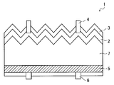
- FIG. 1 is a cross-sectional view showing a first preferred embodiment of a solar battery cell.
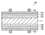
- FIG. 2 is a cross-sectional view showing a second preferred embodiment of the solar battery cell.
- the conductive composition of the present invention is a conductive composition having copper powder (A), a fatty acid silver salt (B), and a thermosetting resin (C).
- the electrically conductive composition of this invention may contain a hardening
- the electrically conductive composition of this invention may contain the solvent (E) as needed from viewpoints of printability etc. so that it may mention later.
- an electrode having a low volume resistivity can be formed.
- Composition This is not clear in detail, but is estimated to be as follows. That is, by using the fatty acid silver salt (B) having a difference between the thermal decomposition peak temperature and the thermal decomposition starting temperature of 40 ° C. or more, silver is produced from the fatty acid silver salt in a wide temperature range, and the silver is the surface of the copper particles. It is considered that the surface oxidation of the copper particles could be suppressed by efficiently covering the surface.
- the copper powder (A) used in the conductive composition of the present invention is not particularly limited, and those blended with conventionally known conductive pastes can be used.
- the copper powder (A) preferably has an average particle diameter of 1.0 to 20 ⁇ m because it has good printability and can form an electrode having a smaller volume resistivity. It is more preferably 0 to 10 ⁇ m.
- the average particle diameter means an average value of the particle diameters, and is measured by using a laser diffraction / scattering type particle size distribution measuring apparatus, and the 50% volume cumulative diameter (D50) calculated using the particle diameter standard as the number is used.
- D50 volume cumulative diameter
- a commercially available product can be used as such copper powder (A).
- Specific examples thereof include Cu-HWQ (average particle size: 3.0 ⁇ m, manufactured by Fukuda Metal Foil Powder Co., Ltd.), FCC. -TBX (average particle size: 5.05 ⁇ m, manufactured by Fukuda Metal Foil Powder Co., Ltd.)
- the fatty acid silver salt (B) used in the conductive composition of the present invention is a fatty acid silver salt in which the difference between the thermal decomposition peak temperature and the thermal decomposition start temperature is 40 ° C. or higher.
- the pyrolysis peak temperature is a value measured in the temperature range from room temperature to 300 ° C. in the air at a temperature rising rate of 5 ° C./min using a differential thermal-thermogravimetric simultaneous measurement device (TG-DTA). The exothermic peak temperature appearing in the DTA curve.
- the pyrolysis start temperature is measured in the temperature range from room temperature to 300 ° C.
- the fatty acid silver salt (B) has a difference between the thermal decomposition peak temperature and the thermal decomposition starting temperature of 100 ° C. or more because it can form an electrode having a low volume resistivity after the wet heat test.
- the temperature is preferably 100 to 130 ° C. This is presumably because the surface of the copper powder (A) could be more efficiently coated with silver derived from the reduction of the fatty acid silver salt (B).
- the fatty acid silver salt (B) is not particularly limited as long as the difference between the thermal decomposition peak temperature and the thermal decomposition start temperature is 40 ° C. or higher among the silver salts of organic carboxylic acids.
- JP-A-2008-198595 Fatty acid metal salts (particularly tertiary fatty acid silver salts) described in paragraphs [0063] to [0068] of the gazette fatty acid silver described in paragraph [0030] of Japanese Patent No. 4482930, JP 2010-92684 A Secondary fatty acid silver salts described in the paragraphs [0046] to [0056] of the above can be used.
- the content of the fatty acid silver salt (B) is 20 to 100 with respect to 100 parts by mass of the copper powder (A) in terms of the amount of silver produced from the fatty acid silver salt (B). Parts by mass, preferably 30 to 100 parts by mass, and more preferably 40 to 100 parts by mass.
- thermosetting resin (C) used in the conductive composition of the present invention is not particularly limited, and specific examples thereof include an epoxy resin, a polyester resin, a silicone resin, a urethane resin, and the like. You may use, and may use 2 or more types together. Among these, an epoxy resin is preferable because it has a strong adhesion to a silicon substrate and high heat and humidity resistance.
- the epoxy resin as a suitable example of the thermosetting resin (C) is not particularly limited as long as it is a resin composed of a compound having two or more oxirane rings (epoxy groups) in one molecule.
- the equivalent is 90-2000.
- a conventionally well-known epoxy resin can be used as such an epoxy resin.
- epoxy compounds having a bisphenyl group such as bisphenol A type, bisphenol F type, brominated bisphenol A type, hydrogenated bisphenol A type, bisphenol S type, bisphenol AF type, biphenyl type, and polyalkylene Bifunctional glycidyl ether type epoxy resins such as glycol type, alkylene glycol type epoxy compounds, epoxy compounds having a naphthalene ring, and epoxy compounds having a fluorene group; Polyfunctional glycidyl ether type epoxy resins such as phenol novolac type, orthocresol novolak type, trishydroxyphenylmethane type, tetraphenylolethane type; Glycidyl ester epoxy resins of synthetic fatty acids such as dimer acid; N, N, N ′, N′-tetraglycidyldiaminodiphenylmethane (TGDDM), tetraglycidyldiaminodiphenylsulfone (TGDDM), te
- epoxy resins may be used alone or in combination of two or more.
- bisphenol A type epoxy resins and bisphenol F type epoxy resins are preferable from the viewpoints of curability, heat resistance, durability, and cost.
- the content of the thermosetting resin (C) is 1.0 to 100 parts by mass with respect to 100 parts by mass of the copper powder (A) because the volume resistivity of the formed electrode or the like is lower.
- the amount is preferably 50 parts by mass, more preferably 2 to 25 parts by mass.
- the conductive composition of the present invention preferably contains a curing agent (D) composed of a complex of boron trifluoride and an amine compound.
- a complex of boron trifluoride and an amine compound a complex of boron trifluoride and an aliphatic amine (aliphatic primary amine, aliphatic secondary amine, aliphatic tertiary amine), trifluoride
- examples thereof include a complex of boron and an alicyclic amine, a complex of boron trifluoride and an aromatic amine, a complex of boron trifluoride and a heterocyclic amine, and the like.
- the heterocyclic amine may be an alicyclic heterocyclic amine (hereinafter also referred to as an alicyclic heterocyclic amine) or an aromatic heterocyclic amine (hereinafter also referred to as an aromatic heterocyclic amine). Also good.
- Specific examples of the aliphatic primary amine include methylamine, ethylamine, n-propylamine, iso-propylamine, n-butylamine, iso-butylamine, sec-butylamine, n-hexylamine, n-octylamine, 2 -Ethylhexylamine, laurylamine and the like.
- aliphatic secondary amine examples include dimethylamine, diethylamine, methylethylamine, methylpropylamine, di-iso-propylamine, di-n-propylamine, ethylpropylamine, di-n-butylamine, di- Examples include iso-butylamine, dipropenylamine, chlorobutylpropylamine, di (chlorobutyl) amine, di (bromoethyl) amine and the like.
- Specific examples of the aliphatic tertiary amine include trimethylamine, triethylamine, tributylamine, triethanolamine and the like.
- alicyclic amine examples include cyclohexylamine.
- aromatic amines include benzylamine.
- alicyclic heterocyclic amine examples include pyrrolidine, piperidine, 2-pipecoline, 3-pipecoline, 4-pipecoline, 2,4-lupetidine, 2,6-lupetidine, 3,5-lupetidine, piperazine, and homopiperazine.
- aromatic heterocyclic amine examples include pyridine, pyrrole, imidazole, pyridazine, pyrimidine, quinoline, triazine, tetrazine, isoquinoline, quinazoline, naphthyridine, pteridine, acridine, phenazine and the like.
- the curing agent (D) is selected from the group consisting of boron trifluoride piperidine, boron trifluoride ethylamine, and boron trifluoride triethanolamine because the volume resistivity of the formed electrode or the like is lower. A complex is preferred.
- the content of the curing agent (D) is preferably 1 to 15 parts by mass with respect to 100 parts by mass of the epoxy resin, because the volume resistivity of the formed electrode or the like becomes lower. It is more preferable that it is 10 mass parts.
- the conductive composition of the present invention preferably contains a solvent (E) from the viewpoint of workability such as printability.
- the solvent (E) is not particularly limited as long as it can apply the conductive composition of the present invention onto a substrate. Specific examples thereof include butyl carbitol, methyl ethyl ketone, isophorone, ⁇ -terpineol. These may be used, and these may be used alone or in combination of two or more.
- the electrically conductive composition of this invention may contain additives, such as a reducing agent, as needed.
- a reducing agent include ethylene glycols.
- the manufacturing method of the electrically conductive composition of this invention is not specifically limited,
- (D) the method of mixing the said solvent (E), an additive, etc. with a roll, a kneader, an extruder, a universal stirrer etc. is mentioned.
- the solar battery cell of the present invention is a solar battery cell using the above-described conductive composition of the present invention as a collecting electrode.
- a 1st suitable aspect of the photovoltaic cell of this invention comprises the surface electrode by the side of a light-receiving surface, a semiconductor substrate, and a back electrode,
- the said surface electrode and / or the said back electrode are the electroconductivity of this invention mentioned above.
- a solar battery cell formed using the composition can be mentioned.
- the 1st suitable aspect of the photovoltaic cell of this invention is demonstrated using FIG.
- the solar cell 1 includes a surface electrode 4 on the light receiving surface side, a pn junction silicon substrate 7 in which a p layer 5 and an n layer 2 are joined, and a back electrode 6.
- the solar battery cell 1 is preferably provided with an antireflection film 3, for example, by etching the wafer surface to form a pyramidal texture in order to reduce reflectivity.
- an antireflection film 3 for example, by etching the wafer surface to form a pyramidal texture in order to reduce reflectivity.
- the arrangement (pitch), shape, height, width and the like of the electrode are not particularly limited.
- the height of the electrode is usually designed to be several to several tens of ⁇ m, but the ratio of the height and width of the cross section of the electrode formed using the conductive composition of the present invention (height / width) (below) , “Aspect ratio”) can be adjusted to a large value (for example, about 0.4 or more).
- the front surface electrode and the back surface electrode usually have a plurality, but, for example, only a part of the plurality of surface electrodes is formed of the conductive composition of the present invention.
- part of the plurality of front surface electrodes and part of the plurality of back surface electrodes may be formed of the conductive composition of the present invention.
- the antireflection film is a film (film thickness: about 0.05 to 0.1 ⁇ m) formed on a portion of the light receiving surface where the surface electrode is not formed.
- a silicon oxide film, a silicon nitride film, a titanium oxide It is comprised from a film
- the silicon substrate has a pn junction, which means that a second conductivity type light-receiving surface impurity diffusion region is formed on the surface side of the first conductivity type semiconductor substrate.
- the second conductivity type is p-type.
- the impurity imparting p-type include boron and aluminum
- examples of the impurity imparting n-type include phosphorus and arsenic.
- the silicon substrate is not particularly limited, and a known silicon substrate (plate thickness: about 80 to 450 ⁇ m) for forming a solar cell can be used, and either a monocrystalline or polycrystalline silicon substrate can be used. Good.
- the solar battery cell has a large electrode aspect ratio because the surface electrode and / or the back electrode is formed using the conductive composition of the present invention.
- the electromotive force generated by light reception can be efficiently taken out as a current.
- the conductive composition of the present invention described above can also be applied to the formation of the back electrode of an all-back electrode type (so-called back contact type) solar cell, it can also be applied to an all-back electrode type solar cell. Can do.
- the manufacturing method of a photovoltaic cell (1st suitable aspect) is not specifically limited,
- the antireflection film can be formed by a known method such as a plasma CVD method.
- the wiring formation step is a step of forming a wiring by applying the conductive composition of the present invention on a silicon substrate.
- specific examples of the coating method include inkjet, screen printing, gravure printing, offset printing, letterpress printing, and the like.
- the heat treatment step is a step of forming a conductive wiring (electrode) by heat-treating the coating film formed in the wiring forming step.
- a conductive wiring electrode
- the heat treatment step is a step of forming a conductive wiring (electrode) by heat-treating the coating film formed in the wiring forming step.
- the heat treatment is not particularly limited, but is preferably a treatment in which heating (firing) is performed at a relatively low temperature of 150 to 350 ° C. for several seconds to several tens of minutes. When the temperature and time are within this range, an electrode can be easily formed even when an antireflection film is formed on a silicon substrate. Further, in the first preferred embodiment of the solar battery cell of the present invention, since the conductive composition of the present invention is used, good heat treatment (firing) can be achieved even at a relatively low temperature of 150 to 350 ° C. ) Can be applied.
- the heat treatment step may be performed by irradiation with ultraviolet rays or infrared rays.
- the solar battery cell 100 has an n-type single crystal silicon substrate 11 as a center, i-type amorphous silicon layers 12 a and 12 b, and p-type amorphous silicon layers 13 a and n-type amorphous silicon layers above and below it. 13b, transparent conductive layers 14a and 14b, and current collecting electrodes 15a and 15b formed using the above-described conductive composition of the present invention.
- the n-type single crystal silicon substrate is a single crystal silicon layer doped with an n-type impurity. Impurities that give n-type are as described above.
- the i-type amorphous silicon layer is an undoped amorphous silicon layer.
- the p-type amorphous silicon is an amorphous silicon layer doped with an impurity imparting p-type. Impurities that give p-type are as described above.
- the n-type amorphous silicon is an amorphous silicon layer doped with an n-type impurity. Impurities that give n-type are as described above.
- the said collector electrode is a collector electrode formed using the electrically conductive composition of this invention mentioned above. A specific aspect of the current collecting electrode is the same as that of the front surface electrode or the back surface electrode described above.
- Transparent conductive layer Specific examples of the material for the transparent conductive layer include single metal oxides such as zinc oxide, tin oxide, indium oxide, and titanium oxide, indium tin oxide (ITO), indium zinc oxide, indium titanium oxide, tin cadmium oxide, Various metal oxides such as gallium-doped zinc oxide, aluminum-doped zinc oxide, boron-doped zinc oxide, titanium-doped zinc oxide, titanium-doped indium oxide, zirconium-doped indium oxide, and fluorine-doped tin oxide. Can be mentioned.
- ITO indium tin oxide
- ITO indium zinc oxide
- titanium oxide titanium oxide
- tin cadmium oxide Various metal oxides such as gallium-doped zinc oxide, aluminum-doped zinc oxide, boron-doped zinc oxide, titanium-doped zinc oxide, titanium-doped indium oxide, zirconium-doped indium oxide, and fluorine-doped
- the method for producing the solar battery cell is not particularly limited, and can be produced by, for example, the method described in JP 2010-34162 A.
- the i-type amorphous silicon layer 12a is formed on one main surface of the n-type single crystal silicon substrate 11 by a PECVD (plasma enhanced chemical vapor deposition) method or the like.
- a p-type amorphous silicon layer 13a is formed on the formed i-type amorphous silicon layer 12a by PECVD or the like.
- an i-type amorphous silicon layer 12b is formed on the other main surface of the n-type single crystal silicon substrate 11 by PECVD or the like. Further, an n-type amorphous silicon layer 13b is formed on the formed i-type amorphous silicon layer 12b by PECVD or the like.
- transparent conductive layers 14a and 14b such as ITO are formed on the p-type amorphous silicon layer 13a and the n-type amorphous silicon layer 13b by sputtering or the like.
- the conductive composition of the present invention is applied on the formed transparent conductive layers 14a and 14b to form wirings, and the formed wirings are heat-treated to form current collecting electrodes 15a and 15b.
- the method for forming the wiring is the same as the method described in the wiring formation step of the above-described solar battery cell (first preferred embodiment).
- the method of heat-treating the wiring is the same as the method described in the heat treatment step of the above-described solar battery cell (first preferred embodiment), but the heat treatment temperature (firing temperature) is preferably 150 to 200 ° C.
- Examples 1 to 17, Comparative Examples 1 to 6 The copper powder etc. which are shown in the following 2nd table
- ⁇ Adhesion> The evaluation of the adhesion of each formed conductive film to the substrate was performed by a grid peel test. The results are shown in Table 2 below. Specifically, on each of the obtained substrates with conductive coating, 100 1 mm bases (10 ⁇ 10) were made, and cellophane adhesive tape was completely attached on the bases and rubbed 10 times with the belly of the finger. After that, one end of the tape was momentarily pulled apart while keeping one end of the tape at right angles to the conductive film, and the number of base meshes remaining without being completely peeled was examined. It is most preferable that the number of base meshes remaining without being completely peeled is 100, that is, those having not peeled off at all.
- Copper powder Cu-HWQ (shape: spherical, average particle size: 3.0 ⁇ m, manufactured by Fukuda Metal Foil Powder Industry)
- Silver salt of 2-methylpropanoate 50 g of silver oxide (manufactured by Toyo Kagaku Kogyo Co., Ltd.), 38 g of 2-methylpropanoic acid (manufactured by Kanto Chemical Co., Ltd.) and 300 g of methyl ethyl ketone (MEK) were placed in a ball mill and reacted by stirring at room temperature for 24 hours. Subsequently, MEK was removed by suction filtration, and the obtained powder was dried to prepare silver 2-methylpropanoate.
- MEK methyl ethyl ketone
- 2-ethylbutyric acid silver salt 50 g of silver oxide (manufactured by Toyo Chemical Co., Ltd.), 50.13 g of 2-ethylbutyric acid (manufactured by Kanto Chemical Co., Ltd.) and 300 g of MEK were placed in a ball mill and reacted by stirring at room temperature for 24 hours. Subsequently, MEK was removed by suction filtration, and the obtained powder was dried to prepare silver 2-ethylbutyrate.
- Neodecanoic acid silver salt 50 g of silver oxide (manufactured by Toyo Kagaku Kogyo Co., Ltd.), 74.3 g of neodecanoic acid (manufactured by Toyo Gosei Co., Ltd.) and 300 g of MEK were placed in a ball mill and reacted by stirring at room temperature for 24 hours. Next, MEK was removed by suction filtration, and the obtained powder was dried to prepare a silver neodecanoate.
- 2-ethylhexanoic acid silver salt 50 g of silver oxide (manufactured by Toyo Chemical Co., Ltd.), 49.27 g of 2-ethylhexanoic acid (manufactured by Kanto Chemical Co., Ltd.) and 300 g of MEK were placed in a ball mill and reacted by stirring at room temperature for 24 hours. Subsequently, MEK was removed by suction filtration, and the obtained powder was dried to prepare silver 2-ethylhexanoate.
- -Silver stearate 50 g of silver oxide (manufactured by Toyo Chemical Co., Ltd.), 123 g of stearic acid (manufactured by Kanto Chemical Co., Ltd.) and 300 g of MEK were placed in a ball mill and reacted by stirring at room temperature for 24 hours. Subsequently, MEK was removed by suction filtration, and the obtained powder was dried to prepare a silver stearate salt.
- 1,2,3,4-Butanetetracarboxylic acid silver salt First, 50 g of silver oxide (manufactured by Toyo Kagaku Kogyo Co., Ltd.), 25.29 g of 1,2,3,4-butanetetracarboxylic acid (manufactured by Shin Nippon Chemical Co., Ltd.) and 300 g of MEK are put into a ball mill and stirred at room temperature for 24 hours. Was reacted. Subsequently, MEK was removed by suction filtration, and the obtained powder was dried to prepare 1,2,3,4-butanetetracarboxylic acid silver salt.
- Glutaric acid silver salt 50 g of silver oxide (manufactured by Toyo Chemical Co., Ltd.), 28.5 g of glutaric acid (manufactured by Kanto Chemical Co., Ltd.) and 300 g of MEK were placed in a ball mill and reacted by stirring at room temperature for 24 hours. Subsequently, MEK was removed by suction filtration, and the obtained powder was dried to prepare silver glutarate.
- N-butyric acid silver salt 50 g of silver oxide (manufactured by Toyo Chemical Co., Ltd.), 38.01 g of n-butyric acid (manufactured by Kanto Chemical Co., Ltd.) and 300 g of MEK were placed in a ball mill and reacted by stirring at room temperature for 24 hours. Next, MEK was removed by suction filtration, and the obtained powder was dried to prepare silver n-butyrate.
- Silver laurate salt 40 g of silver oxide (manufactured by Toyo Chemical Co., Ltd.), 68 g of lauric acid (manufactured by Kanto Chemical Co., Ltd.) and 300 g of MEK were placed in a ball mill and reacted by stirring at room temperature for 24 hours. Subsequently, MEK was removed by suction filtration, and the obtained powder was dried to prepare silver laurate.
- 4-cyclohexene-1,2-dicarboxylic acid silver salt 50 g of silver oxide (manufactured by Toyo Kagaku Kogyo Co., Ltd.), 36.67 g of 4-cyclohexene-1,2-dicarboxylic acid (manufactured by Shin Nippon Chemical Co., Ltd.) and 300 g of MEK were placed in a ball mill and reacted by stirring at room temperature for 24 hours. . Subsequently, MEK was removed by suction filtration, and the obtained powder was dried to prepare silver 4-cyclohexene-1,2-dicarboxylate.
- Azelaic acid silver salt 50 g of silver oxide (manufactured by Toyo Chemical Co., Ltd.), 40.60 g of azelaic acid (manufactured by Kanto Chemical Co., Ltd.) and 300 g of MEK were put into a ball mill and reacted by stirring at room temperature for 24 hours. Subsequently, MEK was removed by suction filtration, and the obtained powder was dried to prepare azelaic acid silver salt.
- 2,2-bis (hydroxymethyl) -n-butyric acid silver salt 50 g of silver oxide (manufactured by Toyo Kagaku Kogyo Co., Ltd.), 64 g of 2,2-bis (hydroxymethyl) -n-butyric acid (manufactured by Tokyo Chemical Industry Co., Ltd.) and 300 g of MEK were placed in a ball mill and reacted by stirring at room temperature for 24 hours. . Subsequently, MEK was removed by suction filtration, and the obtained powder was dried to prepare 2,2-bis (hydroxymethyl) -n-butyric acid silver salt.
- 2-hydroxyisobutyric acid silver salt 50 g of silver oxide (manufactured by Toyo Kagaku Kogyo Co., Ltd.), 45 g of 2-hydroxyisobutyric acid (manufactured by Tokyo Chemical Industry Co., Ltd.) and 300 g of MEK were placed in a ball mill and reacted by stirring at room temperature for 24 hours. Subsequently, MEK was removed by suction filtration, and the obtained powder was dried to prepare silver 2-hydroxyisobutyrate.
- Silver glycolate 50 g of silver oxide (manufactured by Toyo Chemical Co., Ltd.), 16.40 g of glycolic acid (manufactured by Kanto Chemical Co., Ltd.) and 300 g of MEK were placed in a ball mill and reacted by stirring at room temperature for 24 hours. Next, MEK was removed by suction filtration, and the resulting powder was dried to prepare silver glycolate.
- Hydroxypivalic acid silver salt 50 g of silver oxide (manufactured by Toyo Chemical Co., Ltd.), 25.48 g of hydroxypivalic acid (manufactured by Kanto Chemical Co., Ltd.) and 300 g of MEK were placed in a ball mill and reacted by stirring at room temperature for 24 hours. Subsequently, MEK was removed by suction filtration, and the resulting powder was dried to prepare a hydroxypivalic acid silver salt.
- Malonic acid silver salt 50 g of silver oxide (manufactured by Toyo Kagaku Kogyo Co., Ltd.), 11 g of malonic acid and 300 g of MEK were put into a ball mill and reacted by stirring at room temperature for 24 hours. Subsequently, MEK was removed by suction filtration, and the obtained powder was dried to prepare silver malonate.
- Thermosetting resin bisphenol A type epoxy resin (EP-4100E, manufactured by ADEKA)
- Thermosetting resin bisphenol F type epoxy resin (EP-4901E, manufactured by ADEKA)
- -Thermosetting resin Urethane-modified epoxy resin (EPU-1395, manufactured by ADEKA)
- Curing agent Boron trifluoride ethylamine (manufactured by Stella Chemifa)
- Solvent Terpinel
- the comparison between Examples 1 to 13 reveals that the volume resistivity after the wet heat resistance test can be further reduced when the difference between the thermal decomposition peak temperature and the thermal decomposition start temperature is 100 ° C. or more. Further, from the comparison with Examples 8, 14 and 15, when the content of the thermosetting resin (C) is 1.0 to 50 parts by mass with respect to 100 parts by mass of the copper powder (A), the formed electrode It has been found that the volume resistivity of etc. becomes lower.
Landscapes
- Chemical & Material Sciences (AREA)
- Organic Chemistry (AREA)
- Medicinal Chemistry (AREA)
- Polymers & Plastics (AREA)
- Health & Medical Sciences (AREA)
- Chemical Kinetics & Catalysis (AREA)
- Physics & Mathematics (AREA)
- Dispersion Chemistry (AREA)
- Spectroscopy & Molecular Physics (AREA)
- Conductive Materials (AREA)
- Photovoltaic Devices (AREA)
- Compositions Of Macromolecular Compounds (AREA)
- Life Sciences & Earth Sciences (AREA)
- Engineering & Computer Science (AREA)
- Sustainable Development (AREA)
- Sustainable Energy (AREA)
Abstract
Description
すなわち、本発明者らは、以下の構成により上記課題が解決できることを見出した。
上記脂肪酸銀塩(B)の熱分解ピーク温度と熱分解開始温度との差が40℃以上であり、
上記脂肪酸銀塩(B)の含有量が、上記脂肪酸銀塩(B)から生成する銀の量に換算して、上記銅粉(A)100質量部に対して20~100質量部である、導電性組成物。
(2)上記熱硬化性樹脂(C)の含有量が、上記銅粉(A)100質量部に対して1~50質量部である、上記(1)に記載の導電性組成物。
(4)上記集電電極の下地層として透明導電層を具備する上記(3)に記載の太陽電池セル。
(5)上記(3)または(4)に記載の太陽電池セルを用いた太陽電池モジュール。
また、本発明の導電性組成物を用いれば、低温~中温(450℃未満)、特に低温(150~350℃程度)での焼成であっても、体積抵抗率の低い電極等を形成することができるため、太陽電池セル(特に後述する第2の好適態様)への熱によるダメージを軽減できる効果も有し、非常に有用である。
更に、本発明の導電性組成物を用いれば、酸化インジウムスズ(ITO)やシリコンなどの耐熱性の高い材料のみならず、例えばPETフィルムなどの耐熱性の低い材料上にも電子回路、アンテナ等の回路を容易かつ短時間で作製することができるため非常に有用である。
本発明の導電性組成物は、銅粉(A)と、脂肪酸銀塩(B)と、熱硬化性樹脂(C)とを有する導電性組成物である。
また、本発明の導電性組成物は、熱硬化性樹脂(C)としてエポキシ樹脂を用いた場合には、硬化剤(D)を含有してもよい。
また、本発明の導電性組成物は、後述するように印刷性等の観点から、必要に応じて溶媒(E)を含有していてもよい。
これは、詳細には明らかではないが、およそ以下のとおりと推測される。
すなわち、熱分解ピーク温度と熱分解開始温度との差が40℃以上の脂肪酸銀塩(B)を用いることにより、広い温度領域で脂肪酸銀塩から銀が生成し、その銀が銅粒子の表面を効率よく被覆することにより、銅粒子の表面の酸化を抑制することができたと考えられる。
一方、熱分解ピーク温度と熱分解開始温度との差が40℃未満の脂肪酸銀塩を用いた場合には、瞬時に銀が生成するため、銅粒子の表面を局所的にしか被覆することができず、酸化の抑制が不十分であったと考えられる。このことは、後述する比較例に示す結果からも推測される。
本発明の導電性組成物で用いる銅粉(A)は特に限定されず、従来公知の導電性ペーストで配合されているものを使用することができる。
ここで、平均粒子径とは、粒子径の平均値をいい、レーザー回折・散乱式粒度分布測定装置を用いて測定し、粒子径基準を個数として演算された50%体積累積径(D50)をいう。なお、平均値を算出する基になる粒子径は、銅粉末の断面が楕円形である場合はその長径と短径の合計値を2で割った平均値をいい、正円形である場合はその直径をいう。
本発明の導電性組成物で用いる脂肪酸銀塩(B)は、その熱分解ピーク温度と熱分解開始温度との差が40℃以上となる脂肪酸銀塩である。
ここで、熱分解ピーク温度とは、示差熱-熱重量同時測定装置(TG-DTA)を用い、空気中で昇温速度5℃/分にて室温から300℃までの温度範囲で測定した際のDTA曲線に現れる発熱ピーク温度をいう。
また、熱分解開始温度とは、示差熱-熱重量同時測定装置(TG-DTA)を用い、空気中で昇温速度5℃/分にて室温から300℃までの温度範囲で測定し、重量減少が開始した際の温度をいう。
このような脂肪酸銀塩(B)を用いることにより、上述した通り、脂肪酸銀塩(B)の還元に由来する銀の生成が広い温度領域で生起し、上述した銅粉(A)の表面を効率よく被覆することができると考えられる。
また、脂肪酸銀塩(B)は、耐湿熱試験後の体積抵抗率の低い電極等を形成することができる理由から、熱分解ピーク温度と熱分解開始温度との差が、100℃以上であるのが好ましく、100~130℃であるのがより好ましい。これは、脂肪酸銀塩(B)の還元に由来する銀により、銅粉(A)の表面を更に効率よく被覆することができたためと考えられる。
なお、これらの具体例の熱分解開始温度および熱分解ピーク温度は下記第1表に示す通りである。

本発明の導電性組成物で用いる熱硬化性樹脂(C)は特に限定されず、その具体例としては、エポキシ樹脂、ポリエステル樹脂、シリコーン樹脂、ウレタン樹脂等が挙げられ、これらを1種単独で用いてもよく、2種以上を併用してもよい。
これらのうち、シリコン基板との密着力が強く、耐湿熱性が高いという理由から、エポキシ樹脂であるのが好ましい。
上記熱硬化性樹脂(C)の好適例としてのエポキシ樹脂は、1分子中に2個以上のオキシラン環(エポキシ基)を有する化合物からなる樹脂であれば特に限定されず、一般的に、エポキシ当量が90~2000のものである。
このようなエポキシ樹脂としては、従来公知のエポキシ樹脂を用いることができる。
具体的には、例えば、ビスフェノールA型、ビスフェノールF型、臭素化ビスフェノールA型、水添ビスフェノールA型、ビスフェノールS型、ビスフェノールAF型、ビフェニル型等のビスフェニル基を有するエポキシ化合物や、ポリアルキレングリコール型、アルキレングリコール型のエポキシ化合物や、ナフタレン環を有するエポキシ化合物や、フルオレン基を有するエポキシ化合物等の二官能型のグリシジルエーテル系エポキシ樹脂;
フェノールノボラック型、オルソクレゾールノボラック型、トリスヒドロキシフェニルメタン型、テトラフェニロールエタン型等の多官能型のグリシジルエーテル系エポキシ樹脂;
ダイマー酸等の合成脂肪酸のグリシジルエステル系エポキシ樹脂;
N,N,N′,N′-テトラグリシジルジアミノジフェニルメタン(TGDDM)、テトラグリシジルジアミノジフェニルスルホン(TGDDS)、テトラグリシジル-m-キシリレンジアミン(TGMXDA)、トリグリシジル-p-アミノフェノール、トリグリシジル-m-アミノフェノール、N,N-ジグリシジルアニリン、テトラグリシジル1,3-ビスアミノメチルシクロヘキサン(TG1,3-BAC)、トリグリシジルイソシアヌレート(TGIC)等のグリシジルアミン系エポキシ樹脂;
トリシクロ〔5,2,1,02,6〕デカン環を有するエポキシ化合物、具体的には、例えば、ジシクロペンタジエンとメタクレゾール等のクレゾール類またはフェノール類を重合させた後、エピクロルヒドリンを反応させる公知の製造方法によって得ることができるエポキシ化合物;
脂環型エポキシ樹脂;東レチオコール社製のフレップ10に代表されるエポキシ樹脂主鎖に硫黄原子を有するエポキシ樹脂;ウレタン結合を有するウレタン変性エポキシ樹脂;ポリブタジエン、液状ポリアクリロニトリル-ブタジエンゴムまたはアクリロニトリルブタジエンゴム(NBR)を含有するゴム変性エポキシ樹脂等が挙げられる。
また、これらのうち、硬化性、耐熱性、耐久性およびコストの観点から、ビスフェノールA型エポキシ樹脂、ビスフェノールF型エポキシ樹脂であるのが好ましい。
上記熱硬化性樹脂(C)としてエポキシ樹脂を用いる場合、本発明の導電性組成物は、三フッ化ホウ素とアミン化合物との錯体からなる硬化剤(D)を含有するのが好ましい。
三フッ化ホウ素とアミン化合物との錯体としては、三フッ化ホウ素と脂肪族アミン(脂肪族第1級アミン、脂肪族第2級アミン、脂肪族第3級アミン)との錯体、三フッ化ホウ素と脂環式アミンとの錯体、三フッ化ホウ素と芳香族アミンとの錯体、三フッ化ホウ素と複素環アミンとの錯体などが挙げられる。上記複素環アミンは、脂環式の複素環アミン(以下、脂環式複素環アミンともいう)であっても、芳香族の複素環アミン(以下、芳香族複素環アミンともいう)であってもよい。
脂肪族第1級アミンの具体例としては、メチルアミン、エチルアミン、n-プロピルアミン、iso-プロピルアミン、n-ブチルアミン、iso-ブチルアミン、sec-ブチルアミン、n-ヘキシルアミン、n-オクチルアミン、2-エチルヘキシルアミン、ラウリルアミン等が挙げられる。脂肪族第2級アミンの具体例としては、ジメチルアミン、ジエチルアミン、メチルエチルアミン、メチルプロピルアミン、ジ-iso-プロピルアミン、ジ-n-プロピルアミン、エチルプロピルアミン、ジ-n-ブチルアミン、ジ-iso-ブチルアミン、ジプロペニルアミン、クロロブチルプロピルアミン、ジ(クロロブチル)アミン、ジ(ブロモエチル)アミン等が挙げられる。脂肪族第3級アミンの具体例としては、トリメチルアミン、トリエチルアミン、トリブチルアミン、トリエタノールアミン等が挙げられる。脂環式アミンの具体例としては、シクロヘキシルアミン等が挙げられる。芳香族アミンとしては、ベンジルアミン等が挙げられる。脂環式複素環アミンの具体例としては、ピロリジン、ピペリジン、2-ピペコリン、3-ピペコリン、4-ピペコリン、2,4-ルペチジン、2,6-ルペチジン、3,5-ルペチジン、ピペラジン、ホモピペラジン、N-メチルピペラジン、N-エチルピペラジン、N-プロピルピペラジン、N-メチルホモピペラジン、N-アセチルピペラジン、1-(クロロフェニル)ピペラジン、N-アミノエチルピペリジン、N-アミノプロピルピペリジン、N-アミノエチルピペラジン、N-アミノプロピルピペラジン、モルホリン、N-アミノエチルモルホリン、N-アミノプロピルモルホリン、N-アミノプロピル-2-ピペコリン、N-アミノプロピル-4-ピペコリン、1,4-ビス(アミノプロピル)ピペラジン、トリエチレンジアミン、2-メチルトリエチエレンジアミン等が挙げられる。芳香族複素環アミンの具体例としては、ピリジン、ピロール、イミダゾール、ピリダジン、ピリミジン、キノリン、トリアジン、テトラジン、イソキノリン、キナゾリン、ナフチリジン、プテリジン、アクリジン、フェナジン等が挙げられる。
本発明の導電性組成物は、印刷性等の作業性の観点から、溶媒(E)を含有するのが好ましい。
上記溶媒(E)は、本発明の導電性組成物を基材上に塗布することができるものであれば特に限定されず、その具体例としては、ブチルカルビトール、メチルエチルケトン、イソホロン、α-テルピネオール等が挙げられ、これらを1種単独で用いても2種以上を併用してもよい。
本発明の導電性組成物は、必要に応じて、還元剤等の添加剤を含有していてもよい。
上記還元剤としては、具体的には、例えば、エチレングリコール類等が挙げられる。
本発明の導電性組成物の製造方法は特に限定されず、上記銅粉(A)、上記脂肪酸銀塩(B)および上記熱硬化性樹脂(C)ならびに所望により含有してもよい上記硬化剤(D)、上記溶媒(E)および添加剤等を、ロール、ニーダー、押出し機、万能かくはん機等により混合する方法が挙げられる。
本発明の太陽電池セルは、上述した本発明の導電性組成物を集電電極に用いた太陽電池セルである。
本発明の太陽電池セルの第1の好適な態様としては、受光面側の表面電極、半導体基板および裏面電極を具備し、上記表面電極および/または上記裏面電極が、上述した本発明の導電性組成物を用いて形成される太陽電池セルが挙げられる。
以下に、本発明の太陽電池セルの第1の好適な態様について図1を用いて説明する。
また、図1に示すように、太陽電池セル1は、反射率低減のため、例えば、ウエハ表面にエッチングを施して、ピラミッド状のテクスチャを形成し、反射防止膜3を具備するのが好ましい。
以下に、本発明の太陽電池セルの第1の好適な態様が具備する上記表面電極、裏面電極およびシリコン基板並びに具備していてもよい上記反射防止膜について詳述する。
表面電極および裏面電極は、いずれか一方または両方が本発明の導電性組成物を用いて形成されていれば、電極の配置(ピッチ)、形状、高さ、幅等は特に限定されない。なお、電極の高さは、通常、数~数十μmに設計されるが、本発明の導電性組成物を用いて形成した電極の断面の高さと幅の比率(高さ/幅)(以下、「アスペクト比」という。)を大きく(例えば、0.4程度以上)調整することが可能となる。
ここで、表面電極および裏面電極は、図1に示すように、通常、複数個有するものであるが、例えば、複数の表面電極の一部のみが本発明の導電性組成物で形成されたものであってもよく、複数の表面電極の一部と複数の裏面電極の一部が本発明の導電性組成物で形成されたものであってもよい。
反射防止膜は、受光面の表面電極が形成されていない部分に形成される膜(膜厚:0.05~0.1μm程度)であって、例えば、シリコン酸化膜、シリコン窒化膜、酸化チタン膜、これらの積層膜等から構成されるものである。
ここで、p型を与える不純物としては、ホウ素、アルミニウム等が挙げられ、n型を与える不純物としては、リン、砒素などが挙げられる。
シリコン基板は特に限定されず、太陽電池を形成するための公知のシリコン基板(板厚:80~450μm程度)を用いることができ、また、単結晶または多結晶のいずれのシリコン基板であってもよい。
上記太陽電池セル(第1の好適な態様)の製造方法は特に限定されないが、本発明の導電性組成物をシリコン基板上に塗布して配線を形成する配線形成工程と、形成された配線を熱処理して電極(表面電極および/または裏面電極)を形成する熱処理工程とを有する方法が挙げられる。
なお、太陽電池セルが反射防止層を具備する場合、反射防止膜は、プラズマCVD法等の公知の方法により形成することができる。
以下に、配線形成工程、熱処理工程について詳述する。
上記配線形成工程は、本発明の導電性組成物をシリコン基板上に塗布して配線を形成する工程である。
ここで、塗布方法としては、具体的には、例えば、インクジェット、スクリーン印刷、グラビア印刷、オフセット印刷、凸版印刷等が挙げられる。
上記熱処理工程は、上記配線形成工程で形成された塗膜を熱処理して導電性の配線(電極)を形成する工程である。
配線を熱処理することにより、脂肪酸銀塩(B)から分解される銀が溶融する際に銅粉(A)の表面を被覆しつつ連結し、電極が形成される。
また、本発明の太陽電池セルの第1の好適な態様においては、本発明の導電性組成物を用いているため、150~350℃の比較的低い温度であっても、良好な熱処理(焼成)を施すことができる。
本発明においては、上記配線形成工程で形成された配線は、紫外線または赤外線の照射でも電極を形成することができるため、上記熱処理工程は、紫外線または赤外線の照射によるものであってもよい。
本発明の太陽電池セルの第2の好適な態様としては、n型単結晶シリコン基板を中心にその上下にアモルファスシリコン層および透明導電層(例えば、TCO)を具備し、上記透明導電層を下地層として、上記透明導電層上に上述した本発明の導電性組成物を用いて集電電極を形成した太陽電池(例えばヘテロ接合型太陽電池)セルが挙げられる。上記太陽電池セル(第2の好適な態様)は、単結晶シリコンとアモルファスシリコンとをハイブリッドした太陽電池セルであり、高い変換効率を示す。
以下に、本発明の太陽電池セルの第2の好適な態様について図2を用いて説明する。
上記i型アモルファスシリコン層は、ドープされていないアモルファスシリコン層である。
上記p型アモルファスシリコンは、p型を与える不純物がドープされたアモルファスシリコン層である。p型を与える不純物は上述のとおりである。
上記n型アモルファスシリコンは、n型を与える不純物がドープされたアモルファスシリコン層である。n型を与える不純物は上述のとおりである。
上記集電電極は、上述した本発明の導電性組成物を用いて形成された集電電極である。集電電極の具体的な態様は上述した表面電極または裏面電極と同じである。
上記透明導電層の材料の具体例としては、酸化亜鉛、酸化スズ、酸化インジウム、酸化チタンなどの単一金属酸化物、酸化インジウムスズ(ITO)、酸化インジウム亜鉛、酸化インジウムチタン、酸化スズカドミウム、などの多種金属酸化物、ガリウム添加酸化亜鉛、アルミニウム添加酸化亜鉛、硼素添加酸化亜鉛、チタン添加酸化亜鉛、チタン添加酸化インジウム、ジルコニウム添加酸化インジウム、フッ素添加酸化スズなどのドーピング型金属酸化物などが挙げられる。
上記太陽電池セル(第2の好適な態様)の製造方法は特に限定されないが、例えば、特開2010-34162号公報に記載の方法などで製造することができる。
具体的には、n型単結晶シリコン基板11の片方の主面上に、PECVD(plasma enhanced chemical vapor deposition)法などによって、i型アモルファスシリコン層12aを形成する。さらに、形成したi型アモルファスシリコン層12a上にPECVD法などによってp型アモルファスシリコン層13aを形成する。
次に、n型単結晶シリコン基板11のもう一方の主面上に、PECVD法などによって、i型アモルファスシリコン層12bを形成する。さらに、形成したi型アモルファスシリコン層12b上にPECVD法などによってn型アモルファスシリコン層13bを形成する。
次に、スパッタ法などによって、p型アモルファスシリコン層13a上およびn型アモルファスシリコン層13b上にITOなどの透明導電層14aおよび14bを形成する。
次に、形成した透明導電層14aおよび14b上に本発明の導電性組成物を塗布して配線を形成し、さらに、形成した配線を熱処理することで集電電極15aおよび15bを形成する。
配線を形成する方法は、上述した太陽電池セル(第1の好適な態様)の配線形成工程に記載した方法と同じである。
配線を熱処理する方法は、上述した太陽電池セル(第1の好適な態様)の熱処理工程に記載した方法と同じであるが、熱処理温度(焼成温度)は150~200℃であることが好ましい。
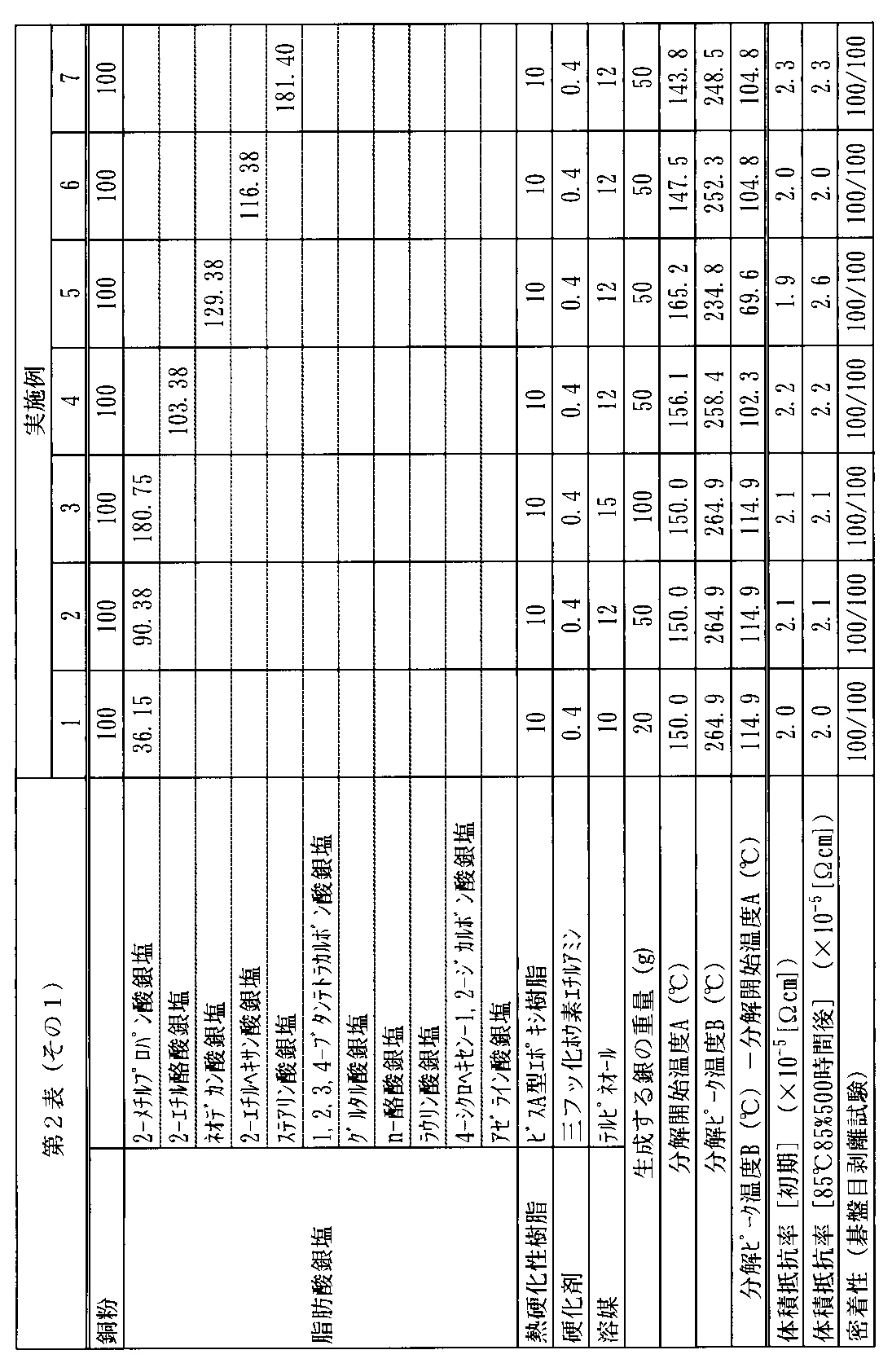
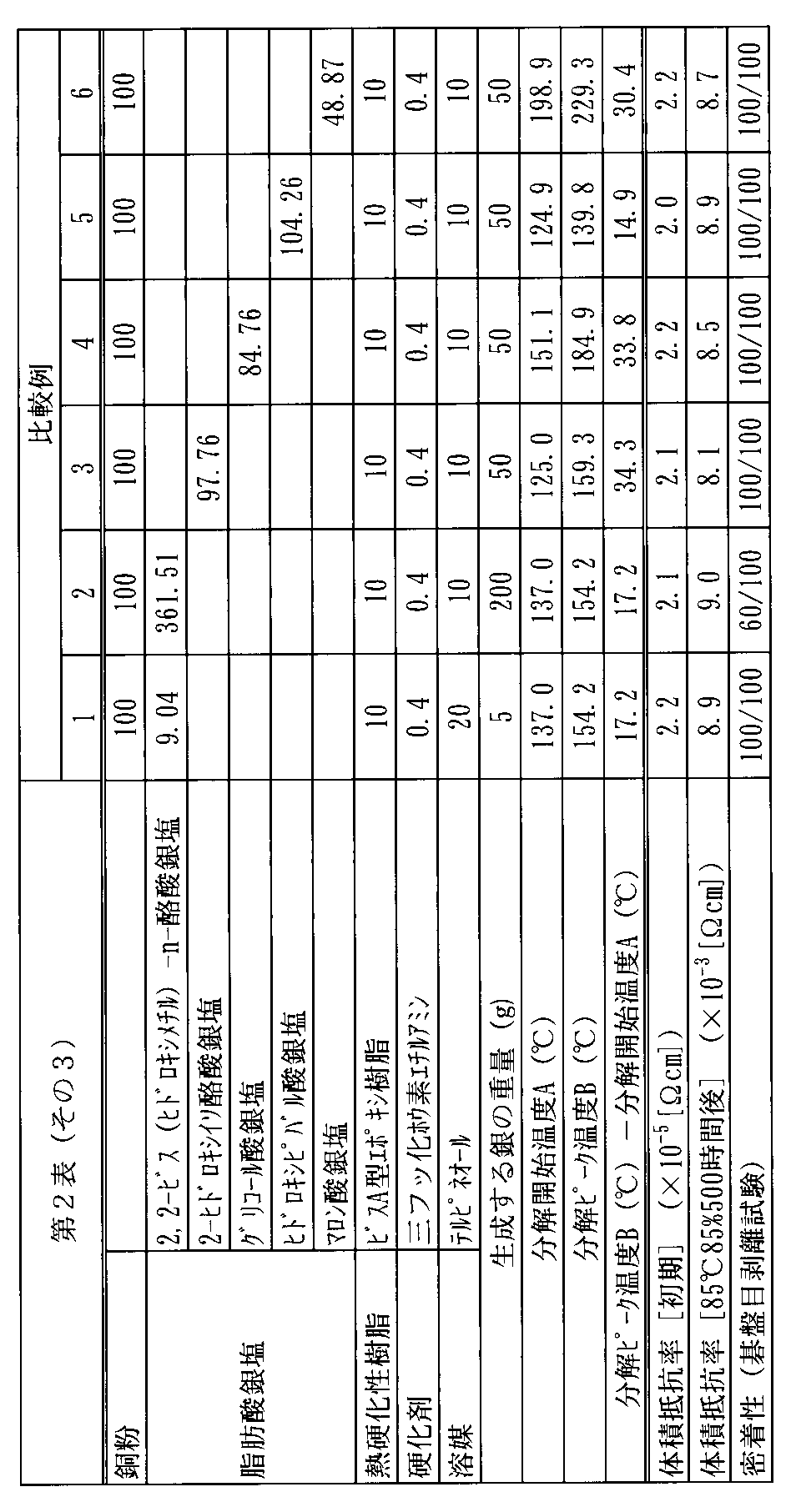
下記第2表に示す銅粉等を下記第2表中に示す組成比(質量部)となるように配合し、これらを混合することにより導電性組成物を調製した。
調製した各導電性組成物を、TCOであるITO蒸着ガラス基板上に、スクリーン印刷で塗布して、25mm×25mmのベタ塗りであるテストパターンを形成した。オーブンにて200℃で30分間乾燥し、導電性被膜を作製した。
作製した各導電性被膜について、作製直後(初期)、および、85℃、85%湿度で500時間放置した後(耐湿熱試験後)の体積抵抗率を、抵抗率計(ロレスターGP、三菱化学社製)を用いた4端子4探針法により測定した。結果を下記第2表に示す。
形成した各導電性被膜の基板に対する密着性の評価は、碁盤目はく離試験により行った。その結果を下記第2表に示す。
具体的には、得られた各導電性被膜付き基板に、1mmの基盤目を100個(10×10)作り、基盤目上にセロハン粘着テープを完全に付着させ、指の腹で10回こすった後、テープの一端を導電性膜に直角に保った状態で瞬間的に引き離し、完全に剥がれないで残った基盤目の数を調べた。完全に剥がれないで残った基盤目数が100、即ち、全く剥がれなかったものが最も好ましい。

・銅粉:Cu-HWQ(形状:球状、平均粒子径:3.0μm、福田金属箔粉工業社製)
酸化銀(東洋化学工業社製)50g、2-メチルプロパン酸(関東化学社製)38gおよびメチルエチルケトン(MEK)300gをボールミルに投入し、室温で24時間撹拌させることにより反応させた。
次いで、吸引ろ過によりMEKを取り除き、得られた粉末を乾燥させることにより、2-メチルプロパン酸銀塩を調製した。
酸化銀(東洋化学工業社製)50g、2-エチル酪酸(関東化学社製)50.13gおよびMEK300gをボールミルに投入し、室温で24時間撹拌させることにより反応させた。
次いで、吸引ろ過によりMEKを取り除き、得られた粉末を乾燥させることにより、2-エチル酪酸銀塩を調製した。
酸化銀(東洋化学工業社製)50g、ネオデカン酸(東洋合成社製)74.3gおよびMEK300gをボールミルに投入し、室温で24時間撹拌させることにより反応させた。
次いで、吸引ろ過によりMEKを取り除き、得られた粉末を乾燥させることにより、ネオデカン酸銀塩を調製した。
酸化銀(東洋化学工業社製)50g、2-エチルヘキサン酸(関東化学社製)49.27gおよびMEK300gをボールミルに投入し、室温で24時間撹拌させることにより反応させた。
次いで、吸引ろ過によりMEKを取り除き、得られた粉末を乾燥させることにより、2-エチルヘキサン酸銀塩を調製した。
酸化銀(東洋化学工業社製)50g、ステアリン酸(関東化学社製)123gおよびMEK300gをボールミルに投入し、室温で24時間撹拌させることにより反応させた。
次いで、吸引ろ過によりMEKを取り除き、得られた粉末を乾燥させることにより、ステアリン酸銀塩を調製した。
まず、酸化銀(東洋化学工業社製)50g、1,2,3,4-ブタンテトラカルボン酸(新日本理化社製)25.29gおよびMEK300gをボールミルに投入し、室温で24時間撹拌させることにより反応させた。
次いで、吸引ろ過によりMEKを取り除き、得られた粉末を乾燥させることによって、1,2,3,4-ブタンテトラカルボン酸銀塩を調製した。
酸化銀(東洋化学工業社製)50g、グルタル酸(関東化学社製)28.5gおよびMEK300gをボールミルに投入し、室温で24時間撹拌させることにより反応させた。
次いで、吸引ろ過によりMEKを取り除き、得られた粉末を乾燥させることにより、グルタル酸銀塩を調製した。
酸化銀(東洋化学工業社製)50g、n-酪酸(関東化学社製)38.01gおよびMEK300gをボールミルに投入し、室温で24時間撹拌させることにより反応させた。
次いで、吸引ろ過によりMEKを取り除き、得られた粉末を乾燥させることにより、n-酪酸銀塩を調製した。
酸化銀(東洋化学工業社製)40g、ラウリン酸(関東化学社製)68gおよびMEK300gをボールミルに投入し、室温で24時間撹拌させることにより反応させた。
次いで、吸引ろ過によりMEKを取り除き、得られた粉末を乾燥させることにより、ラウリン酸銀塩を調製した。
酸化銀(東洋化学工業社製)50g、4-シクロヘキセン-1,2-ジカルボン酸(新日本理化社製)36.67gおよびMEK300gをボールミルに投入し、室温で24時間撹拌させることにより反応させた。
次いで、吸引ろ過によりMEKを取り除き、得られた粉末を乾燥させることにより、4-シクロヘキセン-1,2-ジカルボン酸銀塩を調製した。
酸化銀(東洋化学工業社製)50g、アゼライン酸(関東化学社製)40.60gおよびMEK300gをボールミルに投入し、室温で24時間撹拌させることにより反応させた。
次いで、吸引ろ過によりMEKを取り除き、得られた粉末を乾燥させることにより、アゼライン酸銀塩を調製した。
酸化銀(東洋化学工業社製)50g、2,2-ビス(ヒドロキシメチル)-n-酪酸(東京化成社製)64gおよびMEK300gをボールミルに投入し、室温で24時間撹拌させることにより反応させた。
次いで、吸引ろ過によりMEKを取り除き、得られた粉末を乾燥させることにより、2,2-ビス(ヒドロキシメチル)-n-酪酸銀塩を調製した。
酸化銀(東洋化学工業社製)50g、2-ヒドロキシイソ酪酸(東京化成社製)45gおよびMEK300gをボールミルに投入し、室温で24時間撹拌させることにより反応させた。
次いで、吸引ろ過によりMEKを取り除き、得られた粉末を乾燥させることにより、2-ヒドロキシイソ酪酸銀塩を調製した。
酸化銀(東洋化学工業社製)50g、グリコール酸(関東化学社製)16.40gおよびMEK300gをボールミルに投入し、室温で24時間撹拌させることにより反応させた。
次いで、吸引ろ過によりMEKを取り除き、得られた粉末を乾燥させることにより、グリコール酸銀塩を調製した。
酸化銀(東洋化学工業社製)50g、ヒドロキシピバル酸(関東化学社製)25.48gおよびMEK300gをボールミルに投入し、室温で24時間撹拌させることにより反応させた。
次いで、吸引ろ過によりMEKを取り除き、得られた粉末を乾燥させることにより、ヒドロキシピバル酸銀塩を調製した。
酸化銀(東洋化学工業社製)50g、マロン酸11gおよびMEK300gをボールミルに投入し、室温で24時間撹拌させることにより反応させた。
次いで、吸引ろ過によりMEKを取り除き、得られた粉末を乾燥させることによって、マロン酸銀塩を調製した。
・熱硬化性樹脂:ビスフェノールF型エポキシ樹脂(EP-4901E、ADEKA社製)
・熱硬化性樹脂:ウレタン変性エポキシ樹脂(EPU-1395、ADEKA社製)
・硬化剤:三フッ化ホウ素エチルアミン(ステラケミファ社製)
・溶媒:テルピネール
また、脂肪酸銀塩の含有量が多い比較例2の導電性組成物は、密着性も劣ることが分かった。
これに対し、熱分解ピーク温度と熱分解開始温度との差が40℃以上の脂肪酸銀塩を用いて調製した導電性組成物は、耐湿熱試験後の体積抵抗率も低く、また、基板との密着性も優れることが分かった(実施例1~17)。
特に、実施例1~13の対比から、熱分解ピーク温度と熱分解開始温度との差が100℃以上であると、耐湿熱試験後の体積抵抗率をより低くできることが分かった。
また、実施例8、14および15の対比から、熱硬化性樹脂(C)の含有量が銅粉(A)100質量部に対して1.0~50質量部であると、形成される電極等の体積抵抗率がより低くなることが分かった。
2 n層
3 反射防止膜
4 表面電極
5 p層
6 裏面電極
7 シリコン基板
11 n型単結晶シリコン基板
12a、12b i型アモルファスシリコン層
13a p型アモルファスシリコン層
13b n型アモルファスシリコン層
14a、14b 透明導電層
15a、15b 集電電極
Claims (5)
- 銅粉(A)と、脂肪酸銀塩(B)と、熱硬化性樹脂(C)とを有する導電性組成物であって、
前記脂肪酸銀塩(B)の熱分解ピーク温度と熱分解開始温度との差が40℃以上であり、
前記脂肪酸銀塩(B)の含有量が、前記脂肪酸銀塩(B)から生成する銀の量に換算して、前記銅粉(A)100質量部に対して20~100質量部である、導電性組成物。 - 前記熱硬化性樹脂(C)の含有量が、前記銅粉(A)100質量部に対して1~50質量部である、請求項1に記載の導電性組成物。
- 請求項1または2に記載の導電性組成物を集電電極に用いた太陽電池セル。
- 前記集電電極の下地層として透明導電層を具備する請求項3に記載の太陽電池セル。
- 請求項3または4に記載の太陽電池セルを用いた太陽電池モジュール。
Priority Applications (2)
| Application Number | Priority Date | Filing Date | Title |
|---|---|---|---|
| KR1020167000003A KR20160021178A (ko) | 2013-06-19 | 2014-06-17 | 도전성 조성물 및 태양 전지 셀 |
| JP2015522935A JPWO2014203897A1 (ja) | 2013-06-19 | 2014-06-17 | 導電性組成物および太陽電池セル |
Applications Claiming Priority (2)
| Application Number | Priority Date | Filing Date | Title |
|---|---|---|---|
| JP2013-128582 | 2013-06-19 | ||
| JP2013128582 | 2013-06-19 |
Publications (1)
| Publication Number | Publication Date |
|---|---|
| WO2014203897A1 true WO2014203897A1 (ja) | 2014-12-24 |
Family
ID=52104629
Family Applications (1)
| Application Number | Title | Priority Date | Filing Date |
|---|---|---|---|
| PCT/JP2014/066041 Ceased WO2014203897A1 (ja) | 2013-06-19 | 2014-06-17 | 導電性組成物および太陽電池セル |
Country Status (4)
| Country | Link |
|---|---|
| JP (1) | JPWO2014203897A1 (ja) |
| KR (1) | KR20160021178A (ja) |
| TW (1) | TW201516093A (ja) |
| WO (1) | WO2014203897A1 (ja) |
Cited By (1)
| Publication number | Priority date | Publication date | Assignee | Title |
|---|---|---|---|---|
| JP6357599B1 (ja) * | 2017-02-24 | 2018-07-11 | Dowaエレクトロニクス株式会社 | 導電性ペースト |
Families Citing this family (1)
| Publication number | Priority date | Publication date | Assignee | Title |
|---|---|---|---|---|
| JP6709943B2 (ja) * | 2017-12-13 | 2020-06-17 | ナミックス株式会社 | 導電性ペースト |
Citations (11)
| Publication number | Priority date | Publication date | Assignee | Title |
|---|---|---|---|---|
| JPH10312712A (ja) * | 1997-05-14 | 1998-11-24 | Asahi Chem Ind Co Ltd | はんだ付け可能な導電性ペースト |
| JP2012022804A (ja) * | 2010-07-12 | 2012-02-02 | Yokohama Rubber Co Ltd:The | 導電性組成物および太陽電池セル |
| JP2012023095A (ja) * | 2010-07-12 | 2012-02-02 | Yokohama Rubber Co Ltd:The | 導電性組成物および太陽電池セル |
| JP2012022795A (ja) * | 2010-07-12 | 2012-02-02 | Yokohama Rubber Co Ltd:The | 導電性組成物および太陽電池セル |
| JP2012022798A (ja) * | 2010-07-12 | 2012-02-02 | Yokohama Rubber Co Ltd:The | 導電性組成物および太陽電池セル |
| JP2012023096A (ja) * | 2010-07-12 | 2012-02-02 | Yokohama Rubber Co Ltd:The | 導電性組成物および太陽電池セル |
| JP2012038846A (ja) * | 2010-08-05 | 2012-02-23 | Yokohama Rubber Co Ltd:The | 太陽電池電極用ペーストおよび太陽電池セル |
| WO2012042780A1 (ja) * | 2010-09-29 | 2012-04-05 | 横浜ゴム株式会社 | 導電性組成物、太陽電池セルおよび太陽電池セルの製造方法 |
| JP2012151276A (ja) * | 2011-01-19 | 2012-08-09 | Yokohama Rubber Co Ltd:The | 太陽電池集電電極形成用導電性組成物および太陽電池セル |
| JP2012178456A (ja) * | 2011-02-25 | 2012-09-13 | Yokohama Rubber Co Ltd:The | 太陽電池集電電極形成用導電性組成物および太陽電池セル |
| JP2013045742A (ja) * | 2011-08-26 | 2013-03-04 | Yokohama Rubber Co Ltd:The | 導電性組成物、太陽電池セルおよび太陽電池モジュール |
Family Cites Families (1)
| Publication number | Priority date | Publication date | Assignee | Title |
|---|---|---|---|---|
| JP2008198595A (ja) | 2007-01-16 | 2008-08-28 | Mitsubishi Chemicals Corp | 金属微粒子インクペースト及び有機酸処理金属微粒子 |
-
2014
- 2014-06-17 KR KR1020167000003A patent/KR20160021178A/ko not_active Withdrawn
- 2014-06-17 JP JP2015522935A patent/JPWO2014203897A1/ja active Pending
- 2014-06-17 WO PCT/JP2014/066041 patent/WO2014203897A1/ja not_active Ceased
- 2014-06-19 TW TW103121247A patent/TW201516093A/zh unknown
Patent Citations (11)
| Publication number | Priority date | Publication date | Assignee | Title |
|---|---|---|---|---|
| JPH10312712A (ja) * | 1997-05-14 | 1998-11-24 | Asahi Chem Ind Co Ltd | はんだ付け可能な導電性ペースト |
| JP2012022804A (ja) * | 2010-07-12 | 2012-02-02 | Yokohama Rubber Co Ltd:The | 導電性組成物および太陽電池セル |
| JP2012023095A (ja) * | 2010-07-12 | 2012-02-02 | Yokohama Rubber Co Ltd:The | 導電性組成物および太陽電池セル |
| JP2012022795A (ja) * | 2010-07-12 | 2012-02-02 | Yokohama Rubber Co Ltd:The | 導電性組成物および太陽電池セル |
| JP2012022798A (ja) * | 2010-07-12 | 2012-02-02 | Yokohama Rubber Co Ltd:The | 導電性組成物および太陽電池セル |
| JP2012023096A (ja) * | 2010-07-12 | 2012-02-02 | Yokohama Rubber Co Ltd:The | 導電性組成物および太陽電池セル |
| JP2012038846A (ja) * | 2010-08-05 | 2012-02-23 | Yokohama Rubber Co Ltd:The | 太陽電池電極用ペーストおよび太陽電池セル |
| WO2012042780A1 (ja) * | 2010-09-29 | 2012-04-05 | 横浜ゴム株式会社 | 導電性組成物、太陽電池セルおよび太陽電池セルの製造方法 |
| JP2012151276A (ja) * | 2011-01-19 | 2012-08-09 | Yokohama Rubber Co Ltd:The | 太陽電池集電電極形成用導電性組成物および太陽電池セル |
| JP2012178456A (ja) * | 2011-02-25 | 2012-09-13 | Yokohama Rubber Co Ltd:The | 太陽電池集電電極形成用導電性組成物および太陽電池セル |
| JP2013045742A (ja) * | 2011-08-26 | 2013-03-04 | Yokohama Rubber Co Ltd:The | 導電性組成物、太陽電池セルおよび太陽電池モジュール |
Cited By (3)
| Publication number | Priority date | Publication date | Assignee | Title |
|---|---|---|---|---|
| JP6357599B1 (ja) * | 2017-02-24 | 2018-07-11 | Dowaエレクトロニクス株式会社 | 導電性ペースト |
| WO2018155393A1 (ja) * | 2017-02-24 | 2018-08-30 | Dowaエレクトロニクス株式会社 | 導電性ペースト |
| JP2019083182A (ja) * | 2017-02-24 | 2019-05-30 | Dowaエレクトロニクス株式会社 | 導電性ペースト |
Also Published As
| Publication number | Publication date |
|---|---|
| JPWO2014203897A1 (ja) | 2017-02-23 |
| TW201516093A (zh) | 2015-05-01 |
| KR20160021178A (ko) | 2016-02-24 |
Similar Documents
| Publication | Publication Date | Title |
|---|---|---|
| JP5304932B1 (ja) | 導電性組成物および太陽電池セル | |
| JP5045803B2 (ja) | 導電性組成物および太陽電池セル | |
| CN111480206B (zh) | 导电性糊剂 | |
| JP5321723B1 (ja) | 導電性組成物および太陽電池セル | |
| JP2009146584A (ja) | 導電性ペースト組成物 | |
| JP2016030794A (ja) | 導電性組成物、太陽電池セルおよび太陽電池モジュール | |
| JP5527901B2 (ja) | 太陽電池集電電極形成用導電性組成物および太陽電池セル | |
| WO2018139463A1 (ja) | 導電性組成物 | |
| WO2014203897A1 (ja) | 導電性組成物および太陽電池セル | |
| JPWO2014080789A1 (ja) | 低温焼成用導電性組成物および太陽電池セル | |
| JP2016032022A (ja) | 導電性組成物、太陽電池セルおよび太陽電池モジュール | |
| JP6579108B2 (ja) | 導電性組成物、太陽電池セルおよび太陽電池モジュール | |
| JP2016160415A (ja) | 導電性組成物、太陽電池セルおよび太陽電池モジュール | |
| JP2012023095A (ja) | 導電性組成物および太陽電池セル | |
| JPWO2015118760A1 (ja) | 導電性組成物、太陽電池セルおよび太陽電池モジュール | |
| JP5844091B2 (ja) | 導電性組成物、太陽電池セルおよび太陽電池モジュール | |
| JP2016160413A (ja) | 導電性組成物、太陽電池セルおよび太陽電池モジュール | |
| JP2012178456A (ja) | 太陽電池集電電極形成用導電性組成物および太陽電池セル | |
| KR20140019100A (ko) | 태양 전지 집전 전극 형성용 도전성 조성물 및 태양 전지 셀 | |
| JP2012023082A (ja) | 太陽電池電極用ペーストおよび太陽電池セル | |
| CN103531267A (zh) | 太阳能电池集流电极形成用导电性组合物及太阳能电池单元 | |
| JP6361843B1 (ja) | 導電性組成物 | |
| TW201249935A (en) | Paste used for electrode of solar cell and solar cell unit | |
| TW201409486A (zh) | 太陽能電池集電電極形成用導電性組成物及太陽能電池單元 |
Legal Events
| Date | Code | Title | Description |
|---|---|---|---|
| 121 | Ep: the epo has been informed by wipo that ep was designated in this application |
Ref document number: 14813437 Country of ref document: EP Kind code of ref document: A1 |
|
| ENP | Entry into the national phase |
Ref document number: 2015522935 Country of ref document: JP Kind code of ref document: A |
|
| NENP | Non-entry into the national phase |
Ref country code: DE |
|
| ENP | Entry into the national phase |
Ref document number: 20167000003 Country of ref document: KR Kind code of ref document: A |
|
| 122 | Ep: pct application non-entry in european phase |
Ref document number: 14813437 Country of ref document: EP Kind code of ref document: A1 |