WO2014203562A1 - イオン発生装置およびそれを用いた電気機器 - Google Patents
イオン発生装置およびそれを用いた電気機器 Download PDFInfo
- Publication number
- WO2014203562A1 WO2014203562A1 PCT/JP2014/054797 JP2014054797W WO2014203562A1 WO 2014203562 A1 WO2014203562 A1 WO 2014203562A1 JP 2014054797 W JP2014054797 W JP 2014054797W WO 2014203562 A1 WO2014203562 A1 WO 2014203562A1
- Authority
- WO
- WIPO (PCT)
- Prior art keywords
- electrode
- needle
- housing
- electrodes
- ion generator
- Prior art date
- Legal status (The legal status is an assumption and is not a legal conclusion. Google has not performed a legal analysis and makes no representation as to the accuracy of the status listed.)
- Ceased
Links
Images


Classifications
-
- H—ELECTRICITY
- H01—ELECTRIC ELEMENTS
- H01J—ELECTRIC DISCHARGE TUBES OR DISCHARGE LAMPS
- H01J27/00—Ion beam tubes
- H01J27/02—Ion sources; Ion guns
- H01J27/022—Details
-
- H—ELECTRICITY
- H01—ELECTRIC ELEMENTS
- H01T—SPARK GAPS; OVERVOLTAGE ARRESTERS USING SPARK GAPS; SPARKING PLUGS; CORONA DEVICES; GENERATING IONS TO BE INTRODUCED INTO NON-ENCLOSED GASES
- H01T19/00—Devices providing for corona discharge
- H01T19/04—Devices providing for corona discharge having pointed electrodes
-
- H—ELECTRICITY
- H01—ELECTRIC ELEMENTS
- H01J—ELECTRIC DISCHARGE TUBES OR DISCHARGE LAMPS
- H01J27/00—Ion beam tubes
- H01J27/02—Ion sources; Ion guns
- H01J27/26—Ion sources; Ion guns using surface ionisation, e.g. field effect ion sources, thermionic ion sources
-
- H—ELECTRICITY
- H01—ELECTRIC ELEMENTS
- H01T—SPARK GAPS; OVERVOLTAGE ARRESTERS USING SPARK GAPS; SPARKING PLUGS; CORONA DEVICES; GENERATING IONS TO BE INTRODUCED INTO NON-ENCLOSED GASES
- H01T23/00—Apparatus for generating ions to be introduced into non-enclosed gases, e.g. into the atmosphere
Definitions
- the present invention relates to an ion generator and an electric device using the same, and more particularly to an ion generator that generates ions from needle-like electrodes by electric discharge and an electric device using the same.
- Patent Document 1 Japanese Patent Laid-Open No. 2006-284164
- Patent Document 1 is a plurality of air conditioners that protrude in parallel with each other so that the air blowing direction of the air blower is perpendicular to the air blowing direction and the front end faces the central portion of the air outlet. It has a needle-like negative ion generating electrode.
- the plurality of needle-like electrodes are arranged so as to be parallel to each other with respect to the direction of the air outlet, and the heights of the needle-like electrode to which a high voltage is applied and the grounded needle-like electrode are different.
- a plurality of needle-like electrodes are arranged in the upward direction of the air outlet, and are further covered with a grid-like ridge that protects the needle-like electrodes.
- a main object of the present invention is to provide an ion generator that makes it difficult for a finger to touch a needle-like electrode and can easily clean the needle-like electrode.
- An ion generator includes a housing, a substrate housed in the housing, a needle electrode that is held on the substrate so that a tip portion projects outside the housing, and generates ions by discharge, and the housing An insulating sealing portion for insulatingly sealing the substrate inside, and an electrode protection portion for protecting the needle-shaped electrode outside the housing.
- the housing is provided with an opening through which the tip of the needle electrode is inserted and sealed with an insulating sealing portion, and the electrode protection portion is provided so as to protrude from the tip of the needle electrode from the housing.
- a first protective part and a second protective part that are opposed to each other with a gap on both sides of the electrode.
- At least one of the first protective part and the second protective part is provided with a hole through which the wind toward the needle electrode passes.
- the insulating sealing portion has an electrode sealing region that seals a part of the needle electrode, and the electrode sealing region is exposed to the outside of the housing.
- the base side of the electrode protection part is sealed with an insulating sealing part.
- an induction electrode provided inside the housing and forming an electric field with the needle-like electrode is further provided.
- the induction electrode is sealed with an insulating sealing portion.
- the first protective part and the second protective part are separated from each other in a region not sealed by the insulating sealing part.
- the needle electrode has a positive ion generating electrode for generating positive ions and a negative ion generating electrode for generating negative ions.
- the insulating sealing portion includes a positive insulating sealing portion that seals a part of the axial center portion of the positive ion generating electrode, and a negative insulating sealing member that seals a part of the axial center portion of the negative ion generating electrode. And a stop.
- the positive side insulating sealing portion and the negative side insulating sealing portion are provided at a predetermined interval from each other.
- an electrical apparatus includes the above ion generator and a blower that sends out ions generated from the ion generator to the outside.
- the present invention it is possible to make it difficult for a finger to touch the needle-shaped electrode and to clean the needle-shaped electrode easily.
- the front view of the ion generator by Embodiment 1 of this invention The bottom view of the ion generator by Embodiment 1 of this invention
- the perspective view of the ion generator by Embodiment 1 of this invention AA line sectional view of FIG. Circuit diagram showing the configuration of the ion generator shown in FIG. Sectional drawing which shows the structure of the air cleaner using the ion generator shown in FIG.
- the perspective view of the ion generator by Embodiment 2 of this invention The perspective view of the ion generator by Embodiment 3 of this invention
- the perspective view of the ion generator by Embodiment 4 of this invention Perspective view of an ion generator according to Embodiment 5 of the present invention.
- the perspective view of the ion generator by Embodiment 6 of this invention The perspective view of the ion generator by Embodiment 7 of this invention
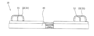
- FIG. 1 is a front view of an ion generator according to an embodiment of the present invention.
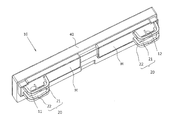
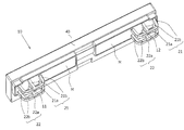
- 2 and 3 are a bottom view and a perspective view, respectively.
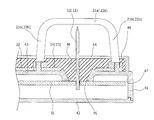
- 4 is a cross-sectional view taken along line AA of FIG.
- the ion generator mainly includes a needle electrode 11 for generating positive ions, a needle electrode 12 for generating negative ions, and an induction electrode 13 for forming an electric field between the needle electrodes 11.
- Inductive electrode 14 for forming an electric field between needle electrode 12, printed circuit boards 31, 32, a substantially rectangular parallelepiped housing 40, and an electrode protector that covers the tips of needle electrodes 11, 12 20.
- the housing 40 has a substantially rectangular shape when viewed from the front, and includes a housing body 41 and a lid body 42.
- the housing body 41 has a substrate installation surface 43 that is substantially rectangular in plan view, and a housing wall surface 46 extends from four sides of one surface (the lower surface in FIG. 4) of the substrate installation surface 43.
- the housing main body is formed in a box shape having an opening at the bottom between the substrate installation surface 43 and the housing wall surface 46.
- wall surfaces 47 extend so as to form square tube shapes on both sides in the longitudinal direction of the housing 40.
- the housing 40 is formed with openings 44 surrounded by wall surfaces 47 on both sides in the longitudinal direction of the housing 40.
- the housing 40 further includes a lid 42 having a substantially rectangular plate shape.
- the lid body 42 covers an opening formed below the housing body.
- the printed circuit boards 31 and 32 are arranged in parallel in the vertical direction in FIG.
- the printed circuit board 31 has a substantially rectangular shape and is disposed on one side of the board installation surface 43.
- the printed circuit board 32 has a substantially rectangular shape and is disposed on the other surface side of the substrate installation surface 43.
- the printed circuit boards 31 and 32 are arranged so that the board installation surface 43 is sandwiched between the two boards.
- the needle electrodes 11 and 12 are provided perpendicular to the printed circuit boards 31 and 32. That is, the base end portion (root portion) of the needle-like electrode 11 is inserted into the hole of the printed board 31, and the axial center part is the center of the hole 45 provided in the housing 40 and the center of the hole 32 a of the printed board 32. It penetrates. Further, the proximal end portion of the needle-like electrode 12 is inserted into the hole of the printed circuit board 31, and the axial center portion penetrates the center of the hole 45 provided in the housing 40 and the center of the hole 32 a of the printed circuit board 32. ing. The hole 45 provided in the housing 40 is closed by the printed circuit board 31. The base ends of the needle-like electrodes 11 and 12 are fixed to the printed circuit board 31 with solder.
- the tip of each of the needle electrodes 11 and 12 has a sharp pointed shape.
- the printed circuit board may be divided into a plurality of parts, and the needle-like electrode 11 and the needle-like electrode 12 may be provided on different boards.
- the acicular electrode 11 and the acicular electrode 12 are provided on the printed circuit board 31 with a predetermined interval. In this embodiment, the interval between the needle electrode 11 and the needle electrode 12 is 102 mm.
- tip part of the acicular electrodes 11 and 12 does not need to have the shape where the front-end
- the induction electrodes 13, 14 are ring-shaped surrounding the periphery of the needle-like electrodes 11, 12 using the wiring layer of the printed circuit board 31 on the surface of one end and the other end in the longitudinal direction of the printed circuit board 32, respectively. Is formed. Inside the induction electrodes 13 and 14, holes 32a penetrating the printed circuit board 32 are opened.
- the induction electrode may not be formed in an annular shape.
- the electrode protection part 20 is provided at two locations so as to correspond to the needle-like electrode 11 at one end in the longitudinal direction of the housing 40 and the needle-like electrode 12 at the other end.
- Each electrode protection part has the 1st protection part 21 and the 2nd protection part 22 which are mutually spaced and opposed on both sides of the tip part of needle-like electrodes 11 and 12.
- the first protection part 21 and the second protection part 22 are arranged side by side with the needle-like electrodes 11, 12 in the short direction of the housing 40.
- the 1st protection part 21 and the 2nd protection part 22 have projected outside from the housing 40, respectively, and have projected outside needle needle electrodes 11 and 12, respectively.
- the 1st protection part 21 and the 2nd protection part 22 are constituted from top plate 21a, support part 21b, top plate 22a, and support part 22b, respectively.
- the top plates 21a and 22a have a strip shape, and two support portions 21b and 22b extend from the both ends of the top plates 21a and 22a toward the housing 40, respectively.
- the first protection part 21a and the second protection part 22b have an arch shape, and an opening is formed between the two support parts 21b and 22b.
- the electrode protection unit 20 is provided with an opening so that the needle-like electrodes 11 and 12 can be seen from the Y direction.
- the openings are provided so that the needle-like electrodes 11 and 12 can be seen from the Y direction.
- the openings may be provided so that the needle-like electrodes 11 and 12 can be seen from the X direction.
- the electrode protection unit 20 is arranged so that the support portions 21 b and 22 b are placed on the surface of the printed circuit board 32 and the printed circuit board 32 is sandwiched between the substrate installation surface 43.
- the support portions 21b and 22b are connected to each other at the end portion (base side) on the housing 40 side and are integrally formed.
- the support portions 21b and 22b may be formed as members that are completely independent of each other.
- the printed circuit board 31 is provided so as to block the hole 45 provided in the housing 40 from one side of the board installation surface 43 (the side opposite to the side from which the tip portions of the needle-like electrodes 11 and 12 protrude). As a result, the space surrounded by the substrate installation surface 43 and the wall surface 47 is sealed except for the opening 44.
- the insulating sealing portion M is formed by filling the opening 44 with an epoxy resin and sealing the opening 44. In FIG. 1 and FIG. 4, the insulating sealing portion M is indicated by oblique lines.
- the insulating sealing part M seals the printed circuit board 32 and the induction electrodes 13 and 14. Further, the insulating sealing portion M seals the base end side of the discharge electrodes 11 and 12. Moreover, the insulation sealing part M has sealed the base side of the 1st protection part 21 and the 2nd protection part. In the present embodiment, the support portion 21b of the first protection portion 21 and the support portion 22b of the second protection portion 22 are connected to each other at the end portion, but are integrated and sealed. The portion M is sealed.
- the insulating sealing is not limited to the epoxy resin, and other insulating sealing materials may be used.
- Insulating sealing portions M are provided independently of each other.
- the insulating sealing portion that seals the proximal end side of the needle electrode 11 is provided at a predetermined interval from the insulating sealing portion that seals the proximal end side of the needle electrode 12.
- circuit components such as a printed circuit board 31, a power supply circuit 33, a step-up transformer 34, and diodes 35 and 36, which will be described later, are provided.
- the space surrounded by the casing body 41 and the lid body 42 is insulated and sealed with an epoxy resin because a step-up transformer for generating a high voltage is disposed.
- the insulation sealing is not limited to the epoxy resin, and other insulating sealing materials may be used.
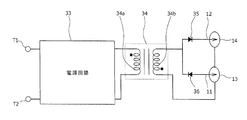
- FIG. 5 is a circuit diagram showing the configuration of the ion generator in the present embodiment.
- the ion generator includes a power terminal T 1, a ground terminal T 2, diodes 35 and 36, and a step-up transformer 34 in addition to the needle electrodes 11 and 12 and the induction electrodes 13 and 14. Parts other than the needle electrodes 11 and 12 and the induction electrodes 13 and 14 in the circuit of FIG. 5 are not shown.
- the positive terminal and the negative terminal of the DC power source are connected to the power terminal T1 and the ground terminal T2, respectively.
- a DC power supply voltage (for example, + 12V or + 15V) is applied to the power supply terminal T1, and the ground terminal T2 is grounded.
- the power supply terminal T1 and the ground terminal T2 are connected to the step-up transformer 34 via the power supply circuit 33.
- the step-up transformer 34 includes a primary winding 34a and a secondary winding 34b.
- One terminal of the secondary winding 34 b is connected to the induction electrodes 13 and 14, and the other terminal is connected to the anode of the diode 35 and the cathode of the diode 36.
- the cathode of the diode 35 is connected to the proximal end of the needle-like electrode 11, and the anode of the diode 36 is connected to the proximal end of the needle-like electrode 12.
- this ion generator When a DC power supply voltage is applied between the power supply terminal T1 and the ground terminal T2, a capacitor (not shown) included in the power supply circuit 33 is charged. The electric charge charged in the capacitor is discharged through the primary winding 34a of the step-up transformer 34, and an impulse voltage is generated in the primary winding 34a.
- the positive ion is a cluster ion in which a plurality of water molecules are clustered around a hydrogen ion (H + ), and is represented as H + (H 2 O) m (where m is an arbitrary natural number).
- a negative ion is a cluster ion in which a plurality of water molecules are clustered around an oxygen ion (O 2 ⁇ ), and O 2 ⁇ (H 2 O) n (where n is 0 or an arbitrary natural number). It is expressed as Moreover, when positive ions and negative ions are released into the room, both ions surround mold fungi and viruses floating in the air and cause a chemical reaction with each other on the surface. Suspended fungi and the like are removed by the action of the active species hydroxyl radical (.OH) generated at that time.
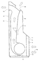
- FIG. 6 is a cross-sectional view showing a configuration of an air cleaner using the ion generator shown in FIGS.
- a suction port 50a is provided on the lower back surface of the main body 50
- air outlets 50b and 50c are provided on the upper back surface and front surface of the main body 50, respectively.
- a duct 51 is provided inside the main body 50, an opening at the lower end of the duct 51 is provided to face the suction port 50a, and an upper end of the duct 51 is connected to the outlets 50b and 50c.
- a cross flow fan 52 is provided at the opening at the lower end of the duct 51, and the ion generator 10 is provided at the center of the duct 51.
- the ion generator 10 is the one shown in FIGS.
- the housing 40 of the ion generator 10 is fixed to the outer wall surface of the duct 51, and the needle-like electrodes 11, 12 and the electrode protection part 12 project through the wall of the duct 51 into the duct 51.
- the two needle-like electrodes 11 and 12 are arranged in a direction (X direction) orthogonal to the direction (Y direction) in which the air in the duct 51 flows.
- a lattice grill 54 made of resin is provided at the suction port 50a, and a mesh-like thin filter 55 is attached to the inside of the grill 54.
- a fan guard 56 is provided at the back of the filter 55 so that foreign matter or a user's finger does not enter the cross flow fan 52.
- the electrode protection part 20 When a high voltage is applied to the needle-like electrodes 11 and 12, an electric field is formed between the needle-like electrodes 11 and 12 and the induction electrodes 13 and 14, and corona discharge is generated at the tips of the needle-like electrodes 11 and 12. As a result, ions are generated.
- the electrode protection part 20 if there is the electrode protection part 20 in the immediate vicinity of the tips of the needle-like electrodes 11 and 12, the electric field generated between the needle-like electrodes 11 and 12 and the induction electrodes 13 and 14 is inhibited.
- the first protection part 21 and the second protection part 22 are arranged so as to face each other with a gap on both sides of the tip part of the needle electrodes 11, 12. 12 does not block the periphery of the tip. Thereby, it is possible to suppress the electric field generated between the needle electrodes 11 and 12 and the induction electrodes 13 and 14 from being inhibited by the electrode protection unit 20.
- the ion generator 10 is replaced by the user after operating for a predetermined time.
- the user can access the ion generator 10 installed in the duct 51 by removing the lid 50 d on the back surface of the main body 50 of the air purifier.
- the first protective portion 21 and the second protective portion 22 protrude outward from the tip portions of the needle-like electrodes 11 and 12, even when the user holds the ion generator 10, the user's finger is It hits the 1st protection part 21 and the 2nd protection part 22, and it becomes difficult to touch the front-end
- the tip portions of the needle-like electrodes 11 and 12 protrude from the housing 40, ions generated at the tip portions of the needle-like electrodes 11 and 12 can be efficiently discharged out of the housing 40.
- the electrode protection unit 20 that covers the tip portions of the needle electrodes 11 and 12 from both sides is provided, it is possible to prevent the user from being injured by touching the tip portions of the needle electrodes 11 and 12. it can.
- the needle electrodes 11 and 12 are sandwiched between the first protection portion 21 and the second protection portion 22b so that the tips of the needle electrodes 11 and 12 can be seen from the Z direction, the tips of the needle electrodes 11 and 12 can be seen. It is possible to prevent the amount of generated ions from being reduced due to the electric field generated around the electrode being inhibited by the electrode protection unit 20. Moreover, since the opening was provided in the electrode protection part 20 so that the needle-like electrodes 11 and 12 can be seen from the Y direction, ions can be efficiently delivered by sending wind in the Y direction.
- the deposit on the needle electrodes 11 and 12 accumulates, so that the spatial distance between the needle electrodes 11 and 12 and the housing 40 is shortened.
- leakage occurs due to dielectric breakdown between the needle-like electrodes 11 and 12 and the housing 40. This phenomenon tends to occur particularly when a large amount of impurities are contained in the air in the space where the ion generator is used.
- the opening 44 of the housing 40 is sealed with an insulating sealing portion M, and a gap into which dust or the like enters the housing 40 is filled. Since the base portions of the needle-like electrodes 11 and 12 are sealed so as to be wrapped in the insulating sealing portion M, when the opening 44 is viewed from the outside of the housing 40, the insulating sealing portion M is shown in FIG. The base end portions of the needle-like electrodes 11 and 12 are completely buried in the inside.
- the insulating sealing portion M seals the periphery of the axial center portion of the needle electrodes 11 and 12 and has a structure in which impurities do not enter the inside of the housing 40. This prevents a leak phenomenon due to accumulation of impurities between the needle-like electrodes 11 and 12 and the components provided inside the housing 40 including the induction electrodes 13 and 14, and stably generates ions. Can do.
- the insulating sealing portion M seals the printed board 31 provided with the needle-like electrodes 11 and 12 and the printed board 32 provided with the induction electrodes 13 and 14. There is no accumulation of deposits between the needle-like electrodes 11 and 12 and the induction electrodes 13 and 14, thereby preventing a leak phenomenon between the needle-like electrodes 11 and 12 and the induction electrodes 13 and 14. Can do.
- the insulating sealing portion M includes a positive ion-side insulating sealing portion that seals a part (base end side) of the needle-like electrode 11 that generates positive ions, and a needle that generates negative ions.
- a negative ion-side insulating sealing portion that seals a part (base end portion side) of the electrode 12 is independently provided at a predetermined interval.
- the first protective part 21 and the second protective part 22 are arranged so as to face each other with a gap on both sides of the tip part of the needle electrodes 11 and 12. Thereby, the needle-like electrodes 11 and 12 can be efficiently cleaned by passing a cleaning member such as a cleaning brush between the first protection part 21 and the second protection part 22.
- the cleaning brush is guided by the first protective part and the second protective part, so that the user can easily clean the needle electrodes 11 and 12. Further, not only the tip portions of the needle electrodes 11 and 12 but also the shaft core portion other than the tip portions of the needle electrodes 11 and 12 can be cleaned.
- An insulating sealing portion M that insulates and seals the proximal end sides of the needle electrodes 11 and 12 is exposed from the opening 44 of the housing 40. Cleaning of the base side portion of the axial center portion protruding from the insulating sealing portion M of the needle electrodes 11 and 12 can be easily performed. Since the exposed surface of the insulating sealing portion M has very high smoothness, cleaning with a cleaning brush can be easily performed.
- the induction electrodes 13 and 14 are formed using the wiring layer of the printed circuit board 32, the induction electrodes 13 and 14 can be formed at low cost, and the cost of the ion generator can be reduced.
- the induction electrodes 13 and 14 are formed using the wiring layer of the printed circuit board 32.
- each of the induction electrodes 13 and 14 may be formed of a metal plate.
- each of the induction electrodes 13 and 14 may not be annular.
- FIG. 6 shows the configuration of the air cleaner using the ion generator of the present embodiment.
- an electric device using the ion generator of the present embodiment other than the air cleaner, for example, an air conditioner , Ion generators, dehumidifiers, humidifiers, refrigerators, fan heaters, washer / dryers, vacuum cleaners, sterilizers, etc.
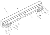
- FIG. 7 is a perspective view showing an ion generation apparatus according to Embodiment 2 of the present invention, and is a view compared with FIG. In FIG. 7, the ion generator differs from the ion generator of FIG. 3 in that the shape of the electrode protection unit 20 is different. Since the configuration other than the electrode protection unit 20 is the same as that of the ion generator in Embodiment 1, the description thereof is omitted.
- the electrode protection part 20 is provided at two locations so as to correspond to the needle-like electrode 11 at one end in the longitudinal direction of the housing 40 and the needle-like electrode 12 at the other end.
- Each electrode protection part has the 1st protection part 21 and the 2nd protection part 22 which are mutually spaced and opposed on both sides of the tip part of needle-like electrodes 11 and 12.
- the first protection part 21 and the second protection part 22 are arranged side by side with the needle-like electrodes 11, 12 in the short direction of the housing 40.
- the 1st protection part 21 and the 2nd protection part 22 have projected outside from the housing 40, respectively, and have projected outside needle needle electrodes 11 and 12, respectively.
- the 1st protection part 21 and the 2nd protection part 22 are constituted from top plate 21a, support part 21b, top plate 22a, and support part 22b, respectively.
- the top plates 21a and 22a have a strip shape, and support portions 21b and 22b extend from the three ends of the top and bottom plates 21a and 22a toward the housing 40, respectively.
- the first protection part 21a and the second protection part 22b have a structure in which a support is further provided in the arch-shaped central part, and two openings are formed between the three support parts 21b and 22b. ing.
- the tips of the needle-like electrodes 11 and 12 are hidden by the support portion 22b serving as a central column, but are provided in the support portions 21b and 22b.
- the wind passes through the formed opening, the wind flows in the immediate vicinity of the needle-like electrodes 11 and 12, so that ions are generated efficiently.
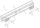
- FIG. 8 is a perspective view showing an ion generating apparatus according to Embodiment 3 of the present invention, and is a view compared with FIG. In FIG. 8, this ion generator differs from the ion generator of FIG. 3 in that the shape of the electrode protection part 20 is different. Since the configuration other than the electrode protection unit 20 is the same as that of the ion generator in Embodiment 1, the description thereof is omitted.
- the electrode protection part 20 is provided at two locations so as to correspond to the needle-like electrode 11 at one end in the longitudinal direction of the housing 40 and the needle-like electrode 12 at the other end.
- Each electrode protection part has the 1st protection part 21 and the 2nd protection part 22 which are mutually spaced and opposed on both sides of the tip part of needle-like electrodes 11 and 12.
- the first protection part 21 and the second protection part 22 are arranged side by side with the needle-like electrodes 11, 12 in the short direction of the housing 40.
- the 1st protection part 21 and the 2nd protection part 22 have projected outside from the housing 40, respectively, and have projected outside needle needle electrodes 11 and 12, respectively.
- the 1st protection part 21 and the 2nd protection part 22 are constituted from top plate 21a, support part 21b, top plate 22a, and support part 22b, respectively.
- the top plates 21a and 22a have a strip shape, and support portions 21b and 22b extend from the three ends of the top and bottom plates 21a and 22a toward the housing 40, respectively.
- the first protection part 21a and the second protection part 22b have a structure in which a support is further provided in the arch-shaped central part, and two openings are formed between the three support parts 21b and 22b. ing.
- the tips of the needle-like electrodes 11 and 12 are hidden by the support portion 22b serving as a central column, but are provided in the support portions 21b and 22b.
- the wind passes through the formed opening, the wind flows in the immediate vicinity of the needle-like electrodes 11 and 12, so that ions are generated efficiently.
- FIG. 9 is a perspective view showing an ion generating apparatus according to Embodiment 4 of the present invention, and is a view compared with FIG.
- the ion generator differs from the ion generator of FIG. 3 in that the shape of the electrode protection unit 20 is different. Since the configuration other than the electrode protection unit 20 is the same as that of the ion generator in Embodiment 1, the description thereof is omitted.
- the electrode protection part 20 is provided at two locations so as to correspond to the needle-like electrode 11 at one end in the longitudinal direction of the housing 40 and the needle-like electrode 12 at the other end.
- Each electrode protection part has the 1st protection part 21 and the 2nd protection part 22 which are mutually spaced and opposed on both sides of the tip part of needle-like electrodes 11 and 12.
- the first protection part 21 and the second protection part 22 are arranged side by side with the needle-like electrodes 11, 12 in the short direction of the housing 40.
- the 1st protection part 21 and the 2nd protection part 22 have projected outside from the housing 40, respectively, and have projected outside needle needle electrodes 11 and 12, respectively.
- the 1st protection part 21 and the 2nd protection part 22 are constituted from top plate 21a, support part 21b, top plate 22a, and support part 22b, respectively.
- the top plates 21a and 22a have a strip shape, and support portions 21b and 22b extend from one end of the top plates 21a and 22a toward the housing 40, respectively.
- the first protection part 21a and the second protection part 22b are L-shaped, and an opening is formed below the top plates 21a and 22a (on the housing 40 side). When the ion generator in this embodiment is seen from the short side direction of the housing 40, the tips of the needle-like electrodes 11 and 12 are visible from the above-described opening.
- FIG. 10 is a perspective view showing an ion generating apparatus according to Embodiment 5 of the present invention, which is compared with FIG. In FIG. 10, this ion generator differs from the ion generator of FIG. 3 in that the shape of the electrode protection unit 20 is different. Since the configuration other than the electrode protection unit 20 is the same as that of the ion generator in Embodiment 1, the description thereof is omitted.
- the electrode protection part 20 is provided at two locations so as to correspond to the needle-like electrode 11 at one end in the longitudinal direction of the housing 40 and the needle-like electrode 12 at the other end.
- Each electrode protection part has the 1st protection part 21 and the 2nd protection part 22 which are mutually spaced and opposed on both sides of the tip part of needle-like electrodes 11 and 12.
- the first protection part 21 and the second protection part 22 are arranged side by side with the needle-like electrodes 11, 12 in the short direction of the housing 40.
- the 1st protection part 21 and the 2nd protection part 22 have projected outside from the housing 40, respectively, and have projected outside needle needle electrodes 11 and 12, respectively.
- the 1st protection part 21 and the 2nd protection part 22 are constituted from top plate 21a, support part 21b, top plate 22a, and support part 22b, respectively.
- the top plates 21a and 22a have a strip shape, and support portions 21b and 22b extend from the center of the top plates 21a and 22a toward the housing 40, respectively.
- the first protection part 21a and the second protection part 22b are T-shaped, and openings are formed at both ends of the support parts 21b and 22b in the region below the top plates 21a and 22a (on the housing 40 side). .
- the tips of the needle-like electrodes 11 and 12 are hidden by the support portion 22b serving as a central column, but are provided in the support portions 21b and 22b.
- the wind passes through the formed opening, the wind flows in the immediate vicinity of the needle-like electrodes 11 and 12, so that ions are generated efficiently.
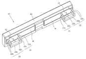
- FIG. 11 is a perspective view showing an ion generator according to Embodiment 6 of the present invention, which is compared with FIG. In FIG. 11, this ion generator differs from the ion generator of FIG. 3 in that the shape of the electrode protection unit 20 is different. Since the configuration other than the electrode protection unit 20 is the same as that of the ion generator in Embodiment 1, the description thereof is omitted.
- the electrode protection part 20 is provided at two locations so as to correspond to the needle-like electrode 11 at one end in the longitudinal direction of the housing 40 and the needle-like electrode 12 at the other end.
- Each electrode protection part has the 1st protection part 21 and the 2nd protection part 22 which are mutually spaced and opposed on both sides of the tip part of needle-like electrodes 11 and 12.
- the first protective part 21 and the second protective part 22 are arranged side by side with the needle-like electrodes 11 and 12 interposed therebetween.
- the 1st protection part 21 and the 2nd protection part 22 have projected outside from the housing 40, respectively, and have projected outside needle needle electrodes 11 and 12, respectively.
- the 1st protection part 21 and the 2nd protection part 22 are constituted from top plate 21a, support part 21b, top plate 22a, and support part 22b, respectively.
- the 1st protection part 21 comprises a rod shape, and the front-end
- the top plate 22b of the second protection portion 22 has an L-shaped plate shape, and the support portion 22b extends toward the housing 40 from the three ends of the top plate 22b and the L-shaped bent portion. Two openings are formed between the three support portions 22b.
- the tips of the needle-like electrodes 11 and 12 are visible from the opening provided between the support portions 22b. Moreover, when the ion generator in this embodiment is seen from the longitudinal direction of the housing 40, the tips of the needle-like electrodes 11 and 12 are visible from the opening provided between the support portions 22b.
- the first protective part 21 and the second protective part 22 are arranged so as to face each other with a gap on both sides of the tip part of the needle electrodes 11 and 12. Thereby, the needle-like electrodes 11 and 12 can be efficiently cleaned by passing a cleaning member such as a cleaning brush between the first protection part 21 and the second protection part 22.
- the needle-like electrodes 11 and 12 can be efficiently cleaned by passing the cleaning brush in an L shape instead of passing it in a straight line.
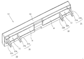
- FIG. 12 is a perspective view showing an ion generating apparatus according to Embodiment 7 of the present invention, which is compared with FIG. In FIG. 12, the ion generator differs from the ion generator of FIG. 3 in that the shape of the electrode protection unit 20 is different. Since the configuration other than the electrode protection unit 20 is the same as that of the ion generator in Embodiment 1, the description thereof is omitted.
- the electrode protection part 20 is provided at two locations so as to correspond to the needle-like electrode 11 at one end in the longitudinal direction of the housing 40 and the needle-like electrode 12 at the other end.
- Each electrode protection part has the 1st protection part 21 and the 2nd protection part 22 which are mutually spaced and opposed on both sides of the tip part of needle-like electrodes 11 and 12.
- the first protection part 21 and the second protection part 22 are arranged side by side in the longitudinal direction of the housing 40 with the needle-like electrodes 11 and 12 interposed therebetween.
- the 1st protection part 21 and the 2nd protection part 22 have projected outside from the housing 40, respectively, and have projected outside needle needle electrodes 11 and 12, respectively.
- the 1st protection part 21 and the 2nd protection part 22 are constituted from top plate 21a, support part 21b, top plate 22a, and support part 22b, respectively.
- the top plates 21a and 22a have a strip shape, and two support portions 21b and 22b extend from the both ends of the top plates 21a and 22a toward the housing 40, respectively.
- the first protection part 21a and the second protection part 22b have an arch shape, and an opening is formed between the two support parts 21b and 22b.
- FIG. 13 is a perspective view showing an ion generator according to Embodiment 8 of the present invention, which is compared with FIG. In FIG. 13, this ion generator differs from the ion generator of FIG. 3 in that the shape of the electrode protection unit 20 is different. Since the configuration other than the electrode protection unit 20 is the same as that of the ion generator in Embodiment 1, the description thereof is omitted.
- the electrode protection unit 20 is provided one by one so as to correspond to a region where the needle-like electrode 11 at one end in the longitudinal direction of the housing 40 and the needle-like electrode 12 at the other end are provided.
- the electrode protection part has a first protection part 21 and a second protection part 22 that are opposed to each other with a gap on both sides of the tip parts of the needle-like electrodes 11 and 12.
- the first protection part 21 and the second protection part 22 are arranged side by side with the needle-like electrodes 11, 12 in the short direction of the housing 40.
- the 1st protection part 21 and the 2nd protection part 22 have projected outside from the housing 40, respectively, and have projected outside needle needle electrodes 11 and 12, respectively.
- the electrode protection unit 20 in this embodiment is configured to sandwich both electrodes of the needle-like electrode 11 and the needle-like electrode 12 with a pair of first protection unit 21 and second protection unit 22.
- the 1st protection part 21 and the 2nd protection part 22 are constituted from top plate 21a, support part 21b, top plate 22a, and support part 22b, respectively.
- the top plates 21a and 22a have a strip shape, and two support portions 21b and 22b extend from the both ends of the top plates 21a and 22a toward the housing 40, respectively.
- the first protection part 21a and the second protection part 22b have an arch shape, and an opening is formed between the two support parts 21b and 22b.
Landscapes
- Engineering & Computer Science (AREA)
- Physics & Mathematics (AREA)
- Plasma & Fusion (AREA)
- Chemical & Material Sciences (AREA)
- Combustion & Propulsion (AREA)
- Disinfection, Sterilisation Or Deodorisation Of Air (AREA)
- Elimination Of Static Electricity (AREA)
Priority Applications (3)
| Application Number | Priority Date | Filing Date | Title |
|---|---|---|---|
| CN201480034114.6A CN105308810B (zh) | 2013-06-20 | 2014-02-27 | 离子发生装置和使用其的电气设备 |
| US14/889,263 US9754757B2 (en) | 2013-06-20 | 2014-02-27 | Ion generation apparatus and electric equipment including the same |
| US15/653,569 US9922792B2 (en) | 2013-06-20 | 2017-07-19 | Ion generation apparatus and electric equipment including the same |
Applications Claiming Priority (2)
| Application Number | Priority Date | Filing Date | Title |
|---|---|---|---|
| JP2013129348A JP6204712B2 (ja) | 2013-06-20 | 2013-06-20 | イオン発生装置およびそれを用いた電気機器 |
| JP2013-129348 | 2013-06-20 |
Related Child Applications (2)
| Application Number | Title | Priority Date | Filing Date |
|---|---|---|---|
| US14/889,263 A-371-Of-International US9754757B2 (en) | 2013-06-20 | 2014-02-27 | Ion generation apparatus and electric equipment including the same |
| US15/653,569 Continuation US9922792B2 (en) | 2013-06-20 | 2017-07-19 | Ion generation apparatus and electric equipment including the same |
Publications (1)
| Publication Number | Publication Date |
|---|---|
| WO2014203562A1 true WO2014203562A1 (ja) | 2014-12-24 |
Family
ID=52104309
Family Applications (1)
| Application Number | Title | Priority Date | Filing Date |
|---|---|---|---|
| PCT/JP2014/054797 Ceased WO2014203562A1 (ja) | 2013-06-20 | 2014-02-27 | イオン発生装置およびそれを用いた電気機器 |
Country Status (5)
| Country | Link |
|---|---|
| US (2) | US9754757B2 (enExample) |
| JP (1) | JP6204712B2 (enExample) |
| CN (2) | CN105308810B (enExample) |
| MY (1) | MY174950A (enExample) |
| WO (1) | WO2014203562A1 (enExample) |
Cited By (2)
| Publication number | Priority date | Publication date | Assignee | Title |
|---|---|---|---|---|
| WO2018055784A1 (ja) * | 2016-09-21 | 2018-03-29 | シャープ株式会社 | 放電装置および電気機器 |
| US12109341B2 (en) * | 2021-11-17 | 2024-10-08 | Sharp Kabushiki Kaisha | Discharge device |
Families Citing this family (20)
| Publication number | Priority date | Publication date | Assignee | Title |
|---|---|---|---|---|
| WO2014172410A1 (en) | 2013-04-18 | 2014-10-23 | American Dryer, Inc. | Sanitizer |
| US9950086B2 (en) | 2014-03-12 | 2018-04-24 | Dm Tec, Llc | Fixture sanitizer |
| US9700643B2 (en) | 2014-05-16 | 2017-07-11 | Michael E. Robert | Sanitizer with an ion generator |
| US10124083B2 (en) | 2015-06-18 | 2018-11-13 | Dm Tec, Llc | Sanitizer with an ion generator and ion electrode assembly |
| JP6612084B2 (ja) | 2015-08-05 | 2019-11-27 | シャープ株式会社 | イオン発生装置および電気機器 |
| JP6591823B2 (ja) * | 2015-08-05 | 2019-10-16 | シャープ株式会社 | イオン発生装置および電気機器 |
| JP6526525B2 (ja) * | 2015-09-02 | 2019-06-05 | シャープ株式会社 | イオン発生装置、イオン発生装置の製造方法、および電気機器 |
| CN109983641B (zh) * | 2016-09-21 | 2020-08-04 | 夏普株式会社 | 放电装置及电气设备 |
| US11576996B2 (en) | 2017-04-10 | 2023-02-14 | Sharp Kabushiki Kaisha | Discharge device and electric machine for improving efficiency of reactive species |
| JP7153712B2 (ja) * | 2017-07-27 | 2022-10-14 | ナチュリオン ピーティーイー.リミテッド | イオン発生装置 |
| WO2019077770A1 (ja) * | 2017-10-20 | 2019-04-25 | シャープ株式会社 | 放電装置 |
| FR3072891B1 (fr) * | 2017-10-28 | 2019-11-08 | Ancilia Protect Ltd | Ioniseur equipe d’un accelerateur de flux ionique notamment pour la protection contre les moustiques |
| US10786818B2 (en) * | 2018-02-09 | 2020-09-29 | Aviation Clean Air, Llc | Aircraft proactive air and surface purification component |
| US11563310B2 (en) | 2021-04-29 | 2023-01-24 | John Walsh | Bipolar ionizer with feedback control |
| US12038204B2 (en) | 2021-04-29 | 2024-07-16 | James Lau | Ionizer feedback control |
| US11173226B1 (en) | 2021-04-29 | 2021-11-16 | Robert J. Mowris | Balanced bipolar ionizer based on unbalanced high-voltage output |
| JP7737282B2 (ja) * | 2021-10-07 | 2025-09-10 | シャープ株式会社 | 放電装置及び電気機器 |
| JP2023074241A (ja) * | 2021-11-17 | 2023-05-29 | シャープ株式会社 | 放電装置 |
| JP2023074240A (ja) * | 2021-11-17 | 2023-05-29 | シャープ株式会社 | 放電装置 |
| KR102683936B1 (ko) * | 2023-04-20 | 2024-07-12 | (주)보성알앤디 | 플라즈마 발생 장치 |
Citations (4)
| Publication number | Priority date | Publication date | Assignee | Title |
|---|---|---|---|---|
| JPH09232068A (ja) * | 1996-02-22 | 1997-09-05 | Sunrise Syst:Kk | 負イオン発生装置 |
| JP2009238602A (ja) * | 2008-03-27 | 2009-10-15 | Kasuga Electric Works Ltd | 直流式バー形除電電極構造 |
| JP2013041681A (ja) * | 2011-08-11 | 2013-02-28 | Sharp Corp | イオン発生装置 |
| JP2013065537A (ja) * | 2011-05-18 | 2013-04-11 | Sharp Corp | イオン発生装置およびそれを用いた電気機器 |
Family Cites Families (4)
| Publication number | Priority date | Publication date | Assignee | Title |
|---|---|---|---|---|
| JP4720413B2 (ja) | 2005-03-07 | 2011-07-13 | パナソニック株式会社 | 空気調和機 |
| JP4701435B2 (ja) * | 2008-08-11 | 2011-06-15 | シャープ株式会社 | イオン発生装置およびそれを用いた電気機器 |
| JP5342867B2 (ja) * | 2008-12-19 | 2013-11-13 | スタンレー電気株式会社 | 半導体発光装置及び駆動方法 |
| JP5192063B2 (ja) * | 2011-05-18 | 2013-05-08 | シャープ株式会社 | イオン発生装置およびそれを用いた電気機器 |
-
2013
- 2013-06-20 JP JP2013129348A patent/JP6204712B2/ja active Active
-
2014
- 2014-02-27 US US14/889,263 patent/US9754757B2/en active Active
- 2014-02-27 WO PCT/JP2014/054797 patent/WO2014203562A1/ja not_active Ceased
- 2014-02-27 CN CN201480034114.6A patent/CN105308810B/zh active Active
- 2014-02-27 MY MYPI2015002716A patent/MY174950A/en unknown
- 2014-02-27 CN CN201710660331.1A patent/CN107230935A/zh active Pending
-
2017
- 2017-07-19 US US15/653,569 patent/US9922792B2/en active Active
Patent Citations (4)
| Publication number | Priority date | Publication date | Assignee | Title |
|---|---|---|---|---|
| JPH09232068A (ja) * | 1996-02-22 | 1997-09-05 | Sunrise Syst:Kk | 負イオン発生装置 |
| JP2009238602A (ja) * | 2008-03-27 | 2009-10-15 | Kasuga Electric Works Ltd | 直流式バー形除電電極構造 |
| JP2013065537A (ja) * | 2011-05-18 | 2013-04-11 | Sharp Corp | イオン発生装置およびそれを用いた電気機器 |
| JP2013041681A (ja) * | 2011-08-11 | 2013-02-28 | Sharp Corp | イオン発生装置 |
Cited By (2)
| Publication number | Priority date | Publication date | Assignee | Title |
|---|---|---|---|---|
| WO2018055784A1 (ja) * | 2016-09-21 | 2018-03-29 | シャープ株式会社 | 放電装置および電気機器 |
| US12109341B2 (en) * | 2021-11-17 | 2024-10-08 | Sharp Kabushiki Kaisha | Discharge device |
Also Published As
| Publication number | Publication date |
|---|---|
| CN105308810A (zh) | 2016-02-03 |
| US20170316910A1 (en) | 2017-11-02 |
| US9922792B2 (en) | 2018-03-20 |
| CN105308810B (zh) | 2017-09-01 |
| JP6204712B2 (ja) | 2017-09-27 |
| CN107230935A (zh) | 2017-10-03 |
| US20160104595A1 (en) | 2016-04-14 |
| MY174950A (en) | 2020-05-28 |
| JP2015005387A (ja) | 2015-01-08 |
| US9754757B2 (en) | 2017-09-05 |
Similar Documents
| Publication | Publication Date | Title |
|---|---|---|
| JP6204712B2 (ja) | イオン発生装置およびそれを用いた電気機器 | |
| JP6415641B2 (ja) | 放電装置および電気機器 | |
| JP6411581B2 (ja) | 放電装置および電気機器 | |
| CN202651620U (zh) | 离子产生装置和使用它的电器设备 | |
| CN202872178U (zh) | 离子产生装置和使用它的电器设备 | |
| JP6936850B2 (ja) | 放電装置および電気機器 | |
| US11458223B2 (en) | Discharge device and electric machine | |
| JP6004525B2 (ja) | イオン発生装置およびそれを用いた電気機器 | |
| JPWO2018055783A1 (ja) | 放電装置および電気機器 | |
| JP6681790B2 (ja) | イオン発生装置および電気機器 | |
| JP6139874B2 (ja) | イオン発生装置およびそれを用いた電気機器 | |
| JP6336186B2 (ja) | 放電装置およびそれを用いた電気機器 | |
| JP2013225383A (ja) | イオン発生装置およびそれを用いた電気機器 | |
| JP6581618B2 (ja) | 放電装置およびそれを用いた電気機器 |
Legal Events
| Date | Code | Title | Description |
|---|---|---|---|
| WWE | Wipo information: entry into national phase |
Ref document number: 201480034114.6 Country of ref document: CN |
|
| 121 | Ep: the epo has been informed by wipo that ep was designated in this application |
Ref document number: 14812910 Country of ref document: EP Kind code of ref document: A1 |
|
| WWE | Wipo information: entry into national phase |
Ref document number: 14889263 Country of ref document: US |
|
| WWE | Wipo information: entry into national phase |
Ref document number: IDP00201507289 Country of ref document: ID |
|
| NENP | Non-entry into the national phase |
Ref country code: DE |
|
| 122 | Ep: pct application non-entry in european phase |
Ref document number: 14812910 Country of ref document: EP Kind code of ref document: A1 |