WO2014203512A1 - 液面検出装置 - Google Patents
液面検出装置 Download PDFInfo
- Publication number
- WO2014203512A1 WO2014203512A1 PCT/JP2014/003178 JP2014003178W WO2014203512A1 WO 2014203512 A1 WO2014203512 A1 WO 2014203512A1 JP 2014003178 W JP2014003178 W JP 2014003178W WO 2014203512 A1 WO2014203512 A1 WO 2014203512A1
- Authority
- WO
- WIPO (PCT)
- Prior art keywords
- liquid level
- exposed surface
- detection device
- level detection
- axial direction
- Prior art date
- Legal status (The legal status is an assumption and is not a legal conclusion. Google has not performed a legal analysis and makes no representation as to the accuracy of the status listed.)
- Ceased
Links
Images


Classifications
-
- G—PHYSICS
- G01—MEASURING; TESTING
- G01F—MEASURING VOLUME, VOLUME FLOW, MASS FLOW OR LIQUID LEVEL; METERING BY VOLUME
- G01F23/00—Indicating or measuring liquid level or level of fluent solid material, e.g. indicating in terms of volume or indicating by means of an alarm
- G01F23/30—Indicating or measuring liquid level or level of fluent solid material, e.g. indicating in terms of volume or indicating by means of an alarm by floats
- G01F23/32—Indicating or measuring liquid level or level of fluent solid material, e.g. indicating in terms of volume or indicating by means of an alarm by floats using rotatable arms or other pivotable transmission elements
- G01F23/38—Indicating or measuring liquid level or level of fluent solid material, e.g. indicating in terms of volume or indicating by means of an alarm by floats using rotatable arms or other pivotable transmission elements using magnetically actuated indicating means
Definitions
- the present disclosure relates to a liquid level detection device that detects a liquid level height of a liquid stored in a container.
- a liquid level detection device that detects the height of a liquid level by measuring the rotation angle of a rotating body that rotates following the liquid level of the liquid.
- the configuration disclosed in Patent Document 1 includes a magnet holder that holds a pair of magnets, and a housing that rotatably supports the magnet holder by a support shaft in which a Hall IC is embedded. ing.
- the density of the magnetic flux penetrating the Hall IC changes as the magnet holder holding the pair of magnets rotates. Therefore, by measuring the rotation angle of the magnet holder based on the output of the Hall IC, the liquid level detection device can detect the height of the liquid level stored in the container.
- the magnet holder of Patent Document 1 is formed with a support shaft and an exposed surface that is located in the protruding direction of the support shaft with respect to each magnet and is exposed in the container.
- a magnetic foreign matter hereinafter referred to as “magnetic foreign matter”
- the inventor of the present application has arrived.
- the present disclosure has been made in view of the above problems, and an object thereof is to provide a liquid level detection device capable of continuously outputting a highly accurate detection result over a long period of use. .
- one aspect of the present disclosure is a liquid level detection device that detects a liquid level height of a liquid stored in a container, and a rotating body that rotates following the liquid level; Rotating with a main body fixed to the container, a fixed body having a support that protrudes from the main body in the axial direction along the rotation axis of the rotating body, and supports the rotating body rotatably, and an arrangement that sandwiches the rotating shaft It has a pair of magnet parts that are held by the body and generates a magnetic flux that penetrates the support part, and an element part that is arranged inside the support part, and outputs a detection result according to the density of the magnetic flux that penetrates the element part
- the rotating body is positioned outside the support portion and each magnet portion in the axial direction to form an exposed surface that is exposed in the container, and each magnet portion is projected outward in the axial direction on the exposed surface. Between the two projection areas, there is a standing wall that is erected axially outward from the exposed surface. It is a standing wall that is
- the exposed surface located in the projecting direction of the support portion and the pair of magnets is provided with a standing wall standing in the projecting direction from the exposed surface. Since the surface of the standing wall is partially away from each magnet, the magnetic force is difficult to reach. Therefore, the magnetic foreign matter contained in the liquid is difficult to adhere to the surface of the standing wall. Therefore, a situation in which the magnetic flux penetrating the support portion is weakened due to the formation of the magnetic circuit by the magnetic foreign matter between the two projection areas where each magnet is projected onto the exposed surface can be avoided. Therefore, the liquid level detection device can continue to output a highly accurate detection result over a long period of use.
- FIG. 2 is a combination of a sectional view of a housing taken along line IIA-IIA in FIG. 1 and a sectional view of a magnet holder taken along line IIB-IIB in FIG. It is a perspective view for demonstrating the structure of the holder cover by 1st embodiment. It is a top view of the holder cover by a first embodiment. It is a figure which shows the modification of FIG.
- the liquid level detection device 100 As shown in FIG. 1, the liquid level detection device 100 according to the first embodiment is installed in a fuel tank 90 that stores fuel as a liquid.
- the liquid level detection device 100 detects the height of the liquid level 91 of the fuel stored in the fuel tank 90 while being held by the fuel pump module 93 or the like.
- the liquid level detection device 100 includes a housing 20, a float 60, a magnet holder 50, a Hall IC 70, and the like.
- the housing 20 shown in FIG. 2 includes an inner case 21, terminals 35a to 35c, an outer case 31, and the like.
- the inner case 21 is made of a resin material such as polyphenylene sulfide (PPS) resin.
- the inner case 21 is provided with an element accommodating chamber 24 that accommodates the Hall IC 70.
- the three terminals 35a to 35c are formed in a strip shape from a conductive material such as phosphor bronze. Each of the terminals 35a to 35c is used for transmission of a detection signal such as a voltage between an external device (for example, a combination meter) and the Hall IC 70.
- the outer case 31 is made of a resin material such as PPS resin.
- the outer case 31 accommodates the inner case 21 by being formed so as to cover the outer side of the inner case 21.
- a shaft portion 32 is formed in the outer case 31.
- the shaft portion 32 protrudes in a cylindrical shape from the main body portion 33 that is fixed to the fuel tank 90 (see FIG. 1) via the fuel pump module 93 (see FIG. 1).
- the shaft portion 32 is fitted in the magnet holder 50 to support the holder 50 in a rotatable manner.
- the float 60 is formed of a material having a specific gravity smaller than that of a fuel such as foamed ebonite.
- the float 60 can float on the liquid level 91 of the fuel.
- the float 60 is supported by the magnet holder 50 via the float arm 65.
- the float arm 65 is formed in a round bar shape from a magnetic material such as stainless steel, and is inserted into a through hole 61 formed in the float 60.
- the magnet holder 50 shown in FIGS. 1 and 2 is formed in a disk shape from a resin material or the like.
- the magnet holder 50 includes a main body 53, a holder cover 80, and the like.
- the magnet holder 50 holds the float arm 65 and is externally fitted to the shaft portion 32 so as to be rotatably supported with respect to the housing 20. With the above-described configuration, the magnet holder 50 rotates relative to the housing 20 integrally with the magnet 51 so as to follow the liquid level 91.
- a pair of magnets 51 are accommodated in the magnet holder 50.
- the pair of magnets 51 are opposed to each other with the shaft portion 32 interposed therebetween by being held in an arrangement that sandwiches the rotation shaft of the holder 50.
- the pair of magnets 51 generates the magnetic flux mf that passes through the Hall IC 70 housed in the element housing chamber 24.
- the Hall IC 70 shown in FIG. 2 is a detection element that detects the relative angle of the magnet holder 50 with respect to the housing 20.
- the Hall IC 70 includes an element portion 71, three lead wires 72, and the like.
- the element portion 71 is formed in a flat plate shape and is accommodated in an element accommodation chamber 24 provided inside the shaft portion 32 so as to be sandwiched between the pair of magnets 51.
- Each lead wire 72 extends from the element portion 71 and is connected to each terminal 35a to 35c.
- the Hall IC 70 receives a magnetic field action from the magnet 51 in a state where a voltage is applied to the element portion 71, thereby generating a voltage corresponding to (proportional to) the density of the magnetic flux mf passing through the Hall IC 70.
- the voltage generated in the Hall IC 70 is measured by an external device as a signal indicating a detection result via each lead wire 72 and each terminal 35a to 35c.
- the reciprocating motion of the float 60 that moves up and down following the fuel is converted into a rotational motion by the float arm 65 held by the magnet holder 50. 65. Therefore, the magnet holder 50 follows the liquid level of the fuel stored in the fuel tank 90 and rotates relative to the housing 20. Due to the relative rotation of the magnet holder 50, the magnetic flux density of the magnetic field acting on the Hall IC 70 changes, whereby the voltage output from the Hall IC 70 changes. In this way, the liquid level detection device 100 realizes the detection of the rotation angle of the magnet holder 50 and consequently the height of the liquid level of the fuel.
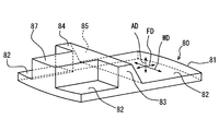
- the holder cover 80 has a main body plate portion 81, a standing wall 83, and an auxiliary wall 87.
- the main body plate portion 81 is formed in a plate shape, and is fitted into the opening 52 of the main body portion 53 from the outside in the axial direction AD that is the protruding direction of the shaft portion 32.
- the main body plate portion 81 is fixed to the main body portion 53 by heat caulking or the like.
- the main body plate portion 81 is located outside the axial direction AD with respect to the shaft portion 32 and each magnet 51.
- an outer surface exposed in the fuel tank 90 (see FIG. 1) is an exposed surface 82.
- projection areas 56 and 57 two areas obtained by projecting the magnets 51 onto the exposed surface 82 toward the outside in the axial direction AD are referred to as projection areas 56 and 57 shown in FIG.
- the intermediate portion of one projection region 56 in the first embodiment is thinned out as the exposed surface 82 is divided by the auxiliary wall 87.
- a region where the shaft portion 32 is projected onto the exposed surface 82 toward the outside in the axial direction AD is defined as a central region 58.
- the direction in which the two magnets 51 face each other and the direction in which the two projection regions 56 and 57 are arranged across the central region 58 is defined as a facing direction FD.
- a direction substantially orthogonal to the facing direction FD along the exposed surface 82 is defined as a width direction WD.
- the standing wall 83 is erected from the exposed surface 82 toward the outside in the axial direction AD to a height exceeding the float arm 65 arranged so as to cross the exposed surface 82. . Therefore, the height dimension h ⁇ b> 1 along the axial direction AD from the exposed surface 82 to the top surface 84 of the standing wall 83 is larger than the diameter d ⁇ b> 1 of the cross section of the float arm 65. As shown in FIGS. 3 and 4, the standing wall 83 extends in the width direction WD along the exposed surface 82. Both end portions in the extending direction of the standing wall 83 reach both edges of the exposed surface 82 in the width direction WD.
- the length of the standing wall 83 in the width direction WD (hereinafter referred to as “width dimension w1”) is the maximum length of each projection region 56, 57 in the width direction WD (hereinafter referred to as “maximum width dimensions w2, w3”). Is substantially the same.
- the standing wall 83 is provided at a position slightly close to the projection area 56 from an intermediate position between the two projection areas 56 and 57. With this arrangement, at least a part of the standing wall 83 is located in the central region 58.
- the side wall of the standing wall 83 adjacent to the float arm 65 is an inclined surface 85. As shown in FIGS. 2 to 4, the inclined surface 85 is inclined in a direction away from the projection region 57 as it is separated from the exposed surface 82 along the axial direction AD.
- the auxiliary wall 87 is formed on the opposite side of the projection region 57 with the standing wall 83 interposed therebetween.
- the auxiliary wall 87 is erected from the exposed surface 82 to the outside in the axial direction AD to substantially the same height as the erected wall 83.
- the auxiliary wall 87 extends from the center of the standing wall 83 in the width direction WD to the outer edge of the exposed surface 82 along the facing direction FD.
- the auxiliary wall 87 is continuous with the standing wall 83 and has a shape extending in a direction orthogonal to the standing wall 83 to increase the strength of the standing wall 83 and the main body plate portion 81.
- magnetic foreign matters such as iron powder can be contained.
- Such iron powder or the like can adhere to the outer surface of the magnet holder 50 by the magnetic force of each magnet 51.
- the standing wall 83 shown in FIG. 2 exhibits a function of preventing such adhesion of iron powder and the like. More specifically, the outer surface of the standing wall 83 erected from the exposed surface 82, particularly the top surface 84, is kept away from each magnet 51. Therefore, the magnetic force of each magnet 51 is difficult to reach the top surface 84. For this reason, the range in which the iron powder easily adheres to the magnet holder 50 is limited to the exposed surfaces 82 on both sides of the standing wall 83, and iron powder or the like hardly adheres to the outer surface of the standing wall 83.
- the situation where the weakness is weakened can be avoided.
- the liquid level detection device 100 can continue to output a highly accurate detection result from the Hall IC 70 over a long period of use.
- the standing wall 83 of the first embodiment extends in the width direction WD so as to divide the two projection regions 56 and 57 shown in FIG. With such a shape, a situation in which iron powder or the like continuously adhered from one of the two projection regions 56 and 57 to the other can form a magnetic circuit can be reliably prevented. Therefore, the detection accuracy of the liquid level detection device 100 is kept high.
- the width dimension w1 of the standing wall 83 is ensured to be the same as the maximum width dimensions w2 and w3 of the projection regions 56 and 57, iron powder or the like is placed on the exposed surface 82 so as to go around the standing wall 83 The situation of adhesion can be avoided. In this way, the formation of a magnetic circuit that connects the projection regions 56 and 57 is made more difficult, so that the effect of maintaining the detection accuracy of the liquid level detection device 100 is exhibited with high certainty.
- the standing wall 83 of the first embodiment is positioned between the two projection areas 56 and 57 by being arranged so as to partially overlap the central area 58.
- the standing wall 83 located at approximately the same distance from the two magnets 51 is reliably moved away from both the magnets 51. Therefore, the effect that iron powder or the like is difficult to adhere to the outer surface of the standing wall 83 can be reliably exhibited. Therefore, a situation in which the detection accuracy is deteriorated by the magnetic circuit formed of iron powder or the like can be avoided more reliably.
- the float arm 65 includes two projection regions 56 and 57 together with iron powder and the like attached to the exposed surface 82. Connecting magnetic circuits can be formed. Therefore, the standing wall 83 of the first embodiment is erected up to a height exceeding the float arm 65. According to the above, the situation where a magnetic circuit is formed so that it may get over the standing wall 83 by cooperation of the float arm 65 and iron powder etc. is avoided. Therefore, it is possible to maintain high detection accuracy even in the liquid level detection device 100 including the float arm 65.
- the housing 20 corresponds to a “fixed body”
- the shaft portion 32 corresponds to a “support portion”
- the magnet holder 50 corresponds to a “rotating body”.
- the magnet 51 corresponds to a “magnet part”
- the Hall IC 70 corresponds to a “detection part”
- the fuel tank 90 corresponds to a “container”.
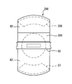
- the second embodiment shown in FIG. 5 is a modification of the first embodiment.
- a configuration corresponding to the auxiliary wall 87 (see FIG. 4) of the first embodiment is omitted. For this reason, one projection region 256 is continuous without interruption at the intermediate portion, like the other projection region 57.
- the side wall adjacent to the float arm 65 is provided substantially perpendicular to the exposed surface 82. Also in the second embodiment described above, by forming the same effect as in the first embodiment, the formation of the magnetic circuit that connects the projection regions 256 and 57 can be prevented. Therefore, it is possible to continue outputting high-precision detection results over a long period of use.
- the standing walls 83 and 283 are formed integrally with the holder covers 80 and 280. According to such a configuration, the strength of the standing wall is easily secured.
- the standing wall may be formed separately from the holder cover and attached to the cover. With such a configuration, the standing wall can be formed of a nonmagnetic material that is less likely to pass the magnetic flux mf than the resin material described above.
- the holder cover that forms the exposed surface may be configured integrally with the main body.
- the standing walls 83 and 283 have a shape extending in the width direction WD.
- the shape of the standing wall may be changed as appropriate.
- the extending direction of the standing wall may be a direction shifted from the width direction WD as long as it intersects the facing direction FD.
- the width dimension w1 (see FIG. 4) of the standing wall may greatly exceed the maximum width dimensions w2 and w3 of each projection area, or may be smaller than the maximum width dimensions w2 and w3 of each projection area.
- a plurality of standing walls may be erected between the two projection areas. The position of the standing wall is not limited to the middle between the two projection areas, and may be in the vicinity of one of the projection areas that deviates greatly from the central area.
- the liquid level detection device according to the above embodiment is preferably installed in a fuel tank made of steel plate.
- a steel tank made of steel iron powder or the like is likely to be mixed with long-term use. Therefore, the liquid level detection device in which detection accuracy is stabilized by preventing adhesion of iron powder or the like to the magnet holder is particularly suitable for a fuel tank made of steel plate.
- the float arm 65 crosses the central region 58 of the exposed surface 82.
- the float arm holding form may be changed so as not to cross the exposed surface. With such a form, it becomes easier to prevent the formation of a magnetic circuit.
- the “pair of magnet portions” is formed by the two magnets 51.
- the “pair of magnet portions” is not limited to the above configuration as long as the magnetic flux can act on the Hall IC.
- each of the “pair of magnet portions” may be formed by combining a plurality of magnets.
- two magnetic poles with different polarities magnetized on one magnet may correspond to “a pair of magnet portions”, respectively.
- the specific configurations of the “detection unit” and the “support unit” may be changed as appropriate.
- liquid level detection device 100 for a vehicle that detects the remaining amount of fuel.
- the scope of application of the present disclosure need not be limited to such a liquid level detection device, but may be a liquid level detection device in a container of other liquids mounted on the vehicle, such as brake fluid, engine cooling water, and engine oil. May be.
- present disclosure is applicable not only to vehicles but also to liquid level detection devices provided in liquid containers provided in various consumer devices and various transport machines.
Landscapes
- Physics & Mathematics (AREA)
- General Physics & Mathematics (AREA)
- Fluid Mechanics (AREA)
- Level Indicators Using A Float (AREA)
Priority Applications (3)
| Application Number | Priority Date | Filing Date | Title |
|---|---|---|---|
| US14/898,981 US9857213B2 (en) | 2013-06-20 | 2014-06-16 | Liquid-level detection device |
| BR112015030622-5A BR112015030622B1 (pt) | 2013-06-20 | 2014-06-16 | DISPOSITIVO DE DETECQAO DE NfVEL DE LfQUIDO |
| KR1020157035240A KR101798743B1 (ko) | 2013-06-20 | 2014-06-16 | 액면 검출 장치 |
Applications Claiming Priority (2)
| Application Number | Priority Date | Filing Date | Title |
|---|---|---|---|
| JP2013-129683 | 2013-06-20 | ||
| JP2013129683A JP6107462B2 (ja) | 2013-06-20 | 2013-06-20 | 液面検出装置 |
Publications (1)
| Publication Number | Publication Date |
|---|---|
| WO2014203512A1 true WO2014203512A1 (ja) | 2014-12-24 |
Family
ID=52104263
Family Applications (1)
| Application Number | Title | Priority Date | Filing Date |
|---|---|---|---|
| PCT/JP2014/003178 Ceased WO2014203512A1 (ja) | 2013-06-20 | 2014-06-16 | 液面検出装置 |
Country Status (5)
| Country | Link |
|---|---|
| US (1) | US9857213B2 (https=) |
| JP (1) | JP6107462B2 (https=) |
| KR (1) | KR101798743B1 (https=) |
| BR (1) | BR112015030622B1 (https=) |
| WO (1) | WO2014203512A1 (https=) |
Families Citing this family (1)
| Publication number | Priority date | Publication date | Assignee | Title |
|---|---|---|---|---|
| JP6842454B2 (ja) | 2018-12-25 | 2021-03-17 | 矢崎総業株式会社 | 液位検出装置 |
Citations (3)
| Publication number | Priority date | Publication date | Assignee | Title |
|---|---|---|---|---|
| JP2006313124A (ja) * | 2005-05-09 | 2006-11-16 | Denso Corp | 液面検出装置 |
| JP2009257911A (ja) * | 2008-04-16 | 2009-11-05 | Yazaki Corp | 非接触式液面レベルセンサ |
| JP2012098210A (ja) * | 2010-11-04 | 2012-05-24 | Denso Corp | 液面検出装置 |
Family Cites Families (5)
| Publication number | Priority date | Publication date | Assignee | Title |
|---|---|---|---|---|
| JPH11237275A (ja) | 1998-02-23 | 1999-08-31 | Yazaki Corp | 液面レベルセンサ |
| JP4126159B2 (ja) * | 2001-01-11 | 2008-07-30 | 矢崎総業株式会社 | 回転検出装置用マグネット及び回転検出装置用マグネットの製造方法 |
| JP3975966B2 (ja) | 2003-05-07 | 2007-09-12 | 株式会社デンソー | 液面レベルセンサ |
| JP4720159B2 (ja) | 2004-11-30 | 2011-07-13 | 日本精機株式会社 | 液面検出装置 |
| JP5533736B2 (ja) | 2011-03-01 | 2014-06-25 | 株式会社デンソー | 液面検出装置 |
-
2013
- 2013-06-20 JP JP2013129683A patent/JP6107462B2/ja active Active
-
2014
- 2014-06-16 US US14/898,981 patent/US9857213B2/en active Active
- 2014-06-16 BR BR112015030622-5A patent/BR112015030622B1/pt active IP Right Grant
- 2014-06-16 WO PCT/JP2014/003178 patent/WO2014203512A1/ja not_active Ceased
- 2014-06-16 KR KR1020157035240A patent/KR101798743B1/ko active Active
Patent Citations (3)
| Publication number | Priority date | Publication date | Assignee | Title |
|---|---|---|---|---|
| JP2006313124A (ja) * | 2005-05-09 | 2006-11-16 | Denso Corp | 液面検出装置 |
| JP2009257911A (ja) * | 2008-04-16 | 2009-11-05 | Yazaki Corp | 非接触式液面レベルセンサ |
| JP2012098210A (ja) * | 2010-11-04 | 2012-05-24 | Denso Corp | 液面検出装置 |
Also Published As
| Publication number | Publication date |
|---|---|
| US20160131515A1 (en) | 2016-05-12 |
| BR112015030622A2 (pt) | 2017-07-25 |
| KR20160006232A (ko) | 2016-01-18 |
| JP2015004574A (ja) | 2015-01-08 |
| JP6107462B2 (ja) | 2017-04-05 |
| BR112015030622B1 (pt) | 2020-11-17 |
| KR101798743B1 (ko) | 2017-11-16 |
| US9857213B2 (en) | 2018-01-02 |
Similar Documents
| Publication | Publication Date | Title |
|---|---|---|
| JP4400640B2 (ja) | 液面検出装置 | |
| JP5983494B2 (ja) | 液面検出装置 | |
| WO2011040249A1 (ja) | 回転角度検出装置 | |
| WO2014112004A1 (ja) | 液面検出装置 | |
| JP6107462B2 (ja) | 液面検出装置 | |
| JP4093126B2 (ja) | 液面検出装置 | |
| JP2007132920A (ja) | 液面検出装置 | |
| JP5621517B2 (ja) | 液面検出装置 | |
| JP6477067B2 (ja) | 液面検出装置 | |
| JP6319058B2 (ja) | 液面検出装置 | |
| JP4957644B2 (ja) | 液面検出装置 | |
| JP4973058B2 (ja) | 液面検出装置 | |
| JP3714242B2 (ja) | 液面検出装置 | |
| JP6287772B2 (ja) | 液面検出装置 | |
| JP6372180B2 (ja) | 液面検出装置 | |
| JP2008058231A (ja) | 液面検出装置 | |
| JP6365155B2 (ja) | 液面検出装置 | |
| JP2007240274A (ja) | 液面検出装置 | |
| JP5176755B2 (ja) | 液面検出装置 | |
| JP2018017661A (ja) | 液面検出装置 | |
| JP2006242777A (ja) | 液面検出装置とその出力調整方法 |
Legal Events
| Date | Code | Title | Description |
|---|---|---|---|
| 121 | Ep: the epo has been informed by wipo that ep was designated in this application |
Ref document number: 14813202 Country of ref document: EP Kind code of ref document: A1 |
|
| ENP | Entry into the national phase |
Ref document number: 20157035240 Country of ref document: KR Kind code of ref document: A |
|
| WWE | Wipo information: entry into national phase |
Ref document number: 14898981 Country of ref document: US |
|
| NENP | Non-entry into the national phase |
Ref country code: DE |
|
| REG | Reference to national code |
Ref country code: BR Ref legal event code: B01A Ref document number: 112015030622 Country of ref document: BR |
|
| 122 | Ep: pct application non-entry in european phase |
Ref document number: 14813202 Country of ref document: EP Kind code of ref document: A1 |
|
| ENP | Entry into the national phase |
Ref document number: 112015030622 Country of ref document: BR Kind code of ref document: A2 Effective date: 20151207 |