WO2014203437A1 - 発電機 - Google Patents
発電機 Download PDFInfo
- Publication number
- WO2014203437A1 WO2014203437A1 PCT/JP2014/001874 JP2014001874W WO2014203437A1 WO 2014203437 A1 WO2014203437 A1 WO 2014203437A1 JP 2014001874 W JP2014001874 W JP 2014001874W WO 2014203437 A1 WO2014203437 A1 WO 2014203437A1
- Authority
- WO
- WIPO (PCT)
- Prior art keywords
- rotor
- magnetic pole
- magnetic
- stator
- axial direction
- Prior art date
Links
Images


Classifications
-
- H—ELECTRICITY
- H02—GENERATION; CONVERSION OR DISTRIBUTION OF ELECTRIC POWER
- H02K—DYNAMO-ELECTRIC MACHINES
- H02K1/00—Details of the magnetic circuit
- H02K1/06—Details of the magnetic circuit characterised by the shape, form or construction
- H02K1/22—Rotating parts of the magnetic circuit
- H02K1/24—Rotor cores with salient poles ; Variable reluctance rotors
- H02K1/243—Rotor cores with salient poles ; Variable reluctance rotors of the claw-pole type
-
- H—ELECTRICITY
- H02—GENERATION; CONVERSION OR DISTRIBUTION OF ELECTRIC POWER
- H02K—DYNAMO-ELECTRIC MACHINES
- H02K15/00—Methods or apparatus specially adapted for manufacturing, assembling, maintaining or repairing of dynamo-electric machines
- H02K15/02—Methods or apparatus specially adapted for manufacturing, assembling, maintaining or repairing of dynamo-electric machines of stator or rotor bodies
- H02K15/022—Methods or apparatus specially adapted for manufacturing, assembling, maintaining or repairing of dynamo-electric machines of stator or rotor bodies with salient poles or claw-shaped poles
-
- H—ELECTRICITY
- H02—GENERATION; CONVERSION OR DISTRIBUTION OF ELECTRIC POWER
- H02K—DYNAMO-ELECTRIC MACHINES
- H02K19/00—Synchronous motors or generators
- H02K19/16—Synchronous generators
- H02K19/22—Synchronous generators having windings each turn of which co-operates alternately with poles of opposite polarity, e.g. heteropolar generators
-
- H—ELECTRICITY
- H02—GENERATION; CONVERSION OR DISTRIBUTION OF ELECTRIC POWER
- H02K—DYNAMO-ELECTRIC MACHINES
- H02K3/00—Details of windings
- H02K3/46—Fastening of windings on the stator or rotor structure
- H02K3/52—Fastening salient pole windings or connections thereto
- H02K3/527—Fastening salient pole windings or connections thereto applicable to rotors only
- H02K3/528—Fastening salient pole windings or connections thereto applicable to rotors only of the claw-pole type
Definitions
- the present invention relates to a Landel type generator used for an alternator or the like of an automobile.
- Randel type generators are known as generators used in automobile alternators (Patent Documents 1 and 2).
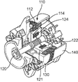
- the Landel generator shown here includes a substantially hollow cylindrical stator 110, a rotating shaft 120 arranged coaxially with the stator 110 inside the stator 110, and first and second rotor cores. 121, 122, a rotor coil (excitation coil) 124, a front cover 130, and a rear cover 140 that is a hollow cylindrical frame.
- the stator 110 has a magnetic core 112 and a stator coil (stator coil) 114.
- the magnetic core 112 is disposed so as to extend inward from a plurality of positions on the inner surface of the casing 130, and the stator coil 114 is wound around each magnetic core 112.
- the magnetic core 112 is usually composed of a large number of non-oriented electrical steel sheets (or silicon steel sheets) laminated together in the axial direction, and each electromagnetic steel sheet has a thickness of 0.5 mm or less.
- the rotary shaft 120 is supported coaxially with the stator 110 and rotatably with respect to the stator 110 by bearings fixed to the front cover 130 and the rear cover 140.
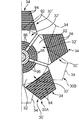
- Each of the rotor cores 121 and 122 is fixed to the outer peripheral surface of the rotating shaft 120 by shrink fitting or the like, and has a donut plate-like base 126 and an axial direction from the base 126. And a plurality of claw-shaped magnetic poles (called claw poles) 128 that protrude.
- the two rotor cores 121 and 122 are arranged so that the magnetic poles 128 face opposite to each other, and the magnetic poles 128 are alternately arranged in the circumferential direction, that is, so as to mesh with each other in a comb shape.
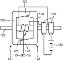
- the rotor coil 124 is disposed between the rotating shaft 120 and the claw-shaped magnetic poles 128 and generates a magnetic flux in the claw-shaped magnetic poles 128 of the rotor cores 121 and 122 when energized.
- the power supply 150 is connected, and the excitation current is supplied from the power supply 150.
- the rotor coil 124 excites the claw-shaped magnetic poles 128 of the two rotor cores 121 and 122 arranged in a comb-teeth shape alternately to the N pole and the S pole.
- the claw-shaped magnetic pole 128 thus excited rotates and the N pole and the S pole are alternately switched, the magnetic flux lines penetrating the inner side of the stator coil 114 change in an alternating manner, thereby the stator.
- a potential difference is generated in the conductor constituting the coil 114, and current is supplied to a load connected to the outside. This is the principle of the Landel type AC generator.
- each comb-like (claw-like) magnetic pole (claw pole) 128 is usually formed as a single member formed from a magnetic metal mass by forging (or cutting in a special small amount). It is integrally formed with the base 126. That is, each of the rotor cores 121 and 122 is usually configured by a bulk magnetic iron block (see Patent Document 2).
- the conventional Randel type generator having the massive rotor cores 121 and 122 as described above has a problem that the use is remarkably limited because of the great energy loss due to the generation of eddy currents depending on the use mode. .
- the stator coil 114 is used.
- a considerably large alternating current including harmonics flows through the stator coil 114, and the demagnetizing magnetic flux lines formed by the stator coil 114 enter the massive magnetic pole 128 of the rotor cores 121 and 122, and are formed on the surface of the magnetic pole 128 and the surface of the magnetic pole 128. Eddy currents can be generated, which can cause significant energy loss.
- the rotor magnetic pole is constituted by a laminated body made up of a large number of electromagnetic steel sheets or the like. Since the rotor magnetic pole has a complicated shape (so-called claw pole) that is integrally connected to the base of the common rotor core and protrudes in a comb-tooth shape along the axial direction from the base, the rotor magnetic pole It is difficult to apply a laminated structure made of a conventional electromagnetic steel sheet or the like as it is.
- Patent Document 1 discloses that the rotor magnetic pole is divided into a plurality of parts, each of which is configured by a planar laminated structure of electromagnetic steel plates.
- Such a structure is fastened for each magnetic pole.
- it is very complicated and has a large number of parts and is difficult to assemble.
- deterioration of effective magnetic resistance due to the use of nonmagnetic inserts such as voids and fasteners generated between the joining surfaces of the electromagnetic steel sheets laminated together cannot be avoided. Therefore, the structure is not practical.
- An object of the present invention is to provide a so-called Landel-type generator that can avoid generation of eddy currents in a rotor core without requiring a complicated structure.
- a generator provided by the present invention includes a plurality of stator cores each including a stator magnetic pole and arranged in a circumferential direction so as to surround a space, and a stator coil wound around the stator core.
- a rotating shaft having a magnetic outer periphery made of a magnetic material in at least a partial region in the axial direction, and a rotating shaft disposed inside the stator so as to be rotatable with respect to the stator;
- a first rotor core and a second rotor core arranged around the magnetic outer periphery so as to rotate together with the rotary shaft on the inner side, and each rotor core is disposed around the magnetic outer periphery;
- a plurality of rotor magnetic pole portions that extend along the axial direction of the rotating shaft from a plurality of positions arranged in the circumferential direction on the outer periphery of the base portion and that can be magnetically coupled to face the stator magnetic poles And the first A rotor magnetic pole portion of the rotor core
- the first and second rotor cores are constituted by a plurality of unit plates that are stacked along the axial direction of the rotating shaft while being electrically insulated from each other.
- Each unit plate is composed of a single thin plate made of a magnetic material, and has a through hole in the center and is arranged around the magnetic outer peripheral portion of the rotary shaft in a state where the rotary shaft is inserted through the through hole.
- a plurality of magnetic pole plate portions extending along the axial direction of the rotating shaft while being inclined radially outward from a plurality of positions arranged in the circumferential direction on the outer periphery of the substrate portion.
- Each of the substrate portions constitutes a base portion of the first and second rotor cores by being laminated in the axial direction, and each of the magnetic pole plate portions is laminated in the axial direction.
- Each of the rotor magnetic pole portions of the two-rotor core is configured.
- the generator shown here is suitable for a Landel type alternator that can also be used as an electric motor.
- the generator according to the present invention is not limited to this, for example, a generator that is used exclusively for power generation or a regenerative brake. It can also be widely applied to those that are also used in the above.
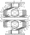
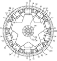
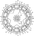
- FIG. 1 and FIG. 2 show the Landell generator according to the first embodiment.
- the generator includes, as main components, a stator 10, a rotating shaft 20, first and second rotor cores 30A and 30B, a rotor coil 40, and a hollow cylinder that collectively accommodates them.
- Shaped casing 50 is
- the stator 10 has a plurality of stator cores (stator cores) 12 including stator magnetic poles, and a stator coil 14 wound around each stator core 12.
- Each of the stator cores 12 is composed of, for example, a large number of electromagnetic steel sheets stacked in the axial direction of the generator (a direction parallel to the rotation shaft 20 described later), and is arranged in the circumferential direction so as to surround the space inside. Thus, it arrange
- the rotating shaft 20 is disposed inside the stator 10 so as to be rotatable with respect to the stator 10, and includes a main body shaft 22 and a magnetic cylindrical body 24.
- the main body shaft 22 has both end portions not shown. These end portions are supported by a bearing provided on the casing 50 or a cover fixed to the casing 50 so as to be rotatable (relative to the stator 10).
- the magnetic cylindrical body 24 is made of a magnetic material capable of forming a necessary magnetic circuit, and in at least a partial region in the axial direction of the main body shaft 22 (region excluding both ends in this embodiment)
- the main body shaft 22 is fitted and fixed to the outside. That is, the magnetic cylindrical body 24 constitutes a magnetic outer peripheral portion of the rotating shaft 20.
- a pressing jig 26 and a fixing nut 28 are disposed on both outer sides of the magnetic cylindrical body 24, respectively.
- Each fixing nut 28 is screwed with a male screw (not shown) formed on the main body shaft 22, and is tightened toward the center, thereby sandwiching the magnetic cylindrical body 24 from both outer sides in the axial direction via the pressing jig 26. .
- the rotating shaft according to the present invention is not limited to the one including the magnetic cylindrical body 24 as long as it has a magnetic outer peripheral portion in an appropriate region in the axial direction.
- the entire rotating shaft may be made of a magnetic material, or a magnetic coating that forms a magnetic outer peripheral portion may be applied to the surface of the body shaft.
- the first and second rotor cores 30A and 30B are arranged around the magnetic cylindrical body 24 so as to rotate together with the rotary shaft 20 inside the stator 10.
- Each rotor core 30 ⁇ / b> A, 30 ⁇ / b> B has a base portion 32 and a plurality of rotor magnetic pole portions 34.
- the base portion 32 is disposed around the magnetic cylindrical body 24, and each rotor magnetic pole portion 34 extends along the axial direction of the rotary shaft 20 from a plurality of positions arranged in the circumferential direction on the outer periphery of the base portion 32.
- These rotor magnetic pole portions 34 can face the stator magnetic poles of the stator 10 from the radially inner side and can be magnetically coupled to the stator magnetic poles.
- the two rotor cores 30A and 30B are arranged so that the rotor magnetic pole portions 34 of the first rotor core 30A and the rotor magnetic pole portions 34 of the second rotor core 30B are alternately arranged in the rotation circumferential direction.
- the rotor cores 30A and 30B are disposed along the rotary shaft 20 in an opposing arrangement such that the comb-shaped magnetic pole portions 34 of the rotor cores 30A and 30B mesh with each other.
- the rotor coil (excitation coil) 40 is interposed between the rotor cores 30A and 30B in the axial direction, and is positioned inside the rotor magnetic pole portion 34 of each rotor core 30A and 30B in the radial direction.
- the rotor coil 40 generates a magnetic flux inside each of the rotor cores 30A and 30B and the stator core by receiving a current supply.
- one rotor magnetic pole portion 34 of the rotor cores 30A and 30B is an N pole
- the other rotor magnetic pole portion 34 is an S pole
- the N pole ⁇ stator core ⁇ S pole ⁇ magnetic cylinder A magnetic circuit that circulates with the body 24 is formed.
- the rotor magnetic pole portion 34 in which the N pole and the S pole are alternately excited in this manner is relatively rotated in the arrangement direction (that is, the circumferential direction) of the rotor magnetic pole portion 34 with respect to the stator 10, thereby An electromotive force is applied to the stator coil 14 of the stator 10.
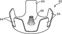
- each of the rotor cores 30A and 30B is constituted by a plurality of unit plates 60 stacked on each other along the axial direction of the rotary shaft 20, as shown in FIG.
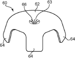
- Each unit plate 60 is made of a magnetic material, and is composed of a single thin plate as shown in FIGS. 4A to 4C.
- These unit plates 60 can also have the same shape as each other, and thereby the production efficiency of the rotor cores 30A and 30B is dramatically increased.
- each unit plate 60 has a donut plate shape having a through hole 63 in the center, and the magnetic cylindrical body 24 that is a magnetic outer peripheral portion of the unit plate 60 in a state where the rotary shaft 20 is inserted into the through hole 63. Arranged around.
- Each of the magnetic pole plate portions 64 extends along the axial direction of the rotary shaft 20 while being inclined radially outward from a plurality of positions arranged in the circumferential direction on the outer periphery of the substrate portion 62.
- the outward inclination angles of the magnetic pole plate portions 64 may be such that the magnetic pole plate portions 64 can be laminated in the axial direction as shown in FIG. It can be freely set according to the specification.
- the substrate parts 62 are laminated in the axial direction in a state of being electrically insulated from each other, thereby constituting the base parts 32 of the first and second rotor cores 30A and 30B, respectively, and the magnetic pole plate parts. 64 are laminated in the axial direction in a state of being electrically insulated from each other, thereby constituting each rotor magnetic pole portion 34 of the first and second rotor cores 30A, 30B.
- the unit plates 60 constituting the rotor cores 30A, 30B can be integrated by, for example, impregnation with an appropriate resin.
- an insulating coating is applied to at least one side surface and end surface of both side surfaces of each unit plate 60.
- each unit plate 60 is shown to be larger than the actual thickness for the sake of convenience, but the actual thickness of each unit plate 60 is very small as will be described later, and thus is greater than the number shown in the drawing.
- the rotor cores 30A and 30B are constituted by a large number (for example, 20 to several tens) of unit plates 60.
- each unit plate 60 is determined by the number of rotor magnetic pole portions 34 of the rotor cores 30A and 30B (FIGS. 2, 3 and 4A to 4C) at the rotational frequency (rated rotational frequency) of the generator.
- the skin depth ⁇ (m) is a depth at which electromagnetic waves penetrate from the sample surface to about 1 / e.
- each unit plate 60 is made of a pure iron-based material
- each unit plate The preferred thickness t of 60 is preferably set in the range of 0.1 mm ⁇ t ⁇ 0.5 mm. That is, the upper limit is about 500 ⁇ m, and from the viewpoint of ease of processing, the upper limit is preferably 300 ⁇ m or less, and more preferably 100 ⁇ m or less. However, since there is a limit to the thickness accuracy by rolling, it is realistic to set the thickness to 30 ⁇ m or more. The lamination of the unit plates 60 having such a small plate thickness enables effective suppression of the generation of eddy currents.
- the tip 65 of the magnetic pole plate portion 64 of each unit plate 60 is aligned along the stator magnetic pole surface that is the inner surface of the stator magnetic pole of the stator 10 by the axial lamination of the unit plates 60. It is possible to form a rotor pole face that is arranged and thereby faces the stator pole face.
- the rotor magnetic pole surface effectively suppresses the generation of eddy currents while allowing smooth magnetic flux to enter from the stator magnetic pole surface.
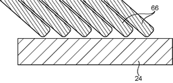
- each unit plate 60 constitutes an inner peripheral edge 66 that extends inward in the radial direction and extends on the same side as the magnetic pole plate portion 64.
- the inner peripheral edge portions 66 are also laminated in the axial direction.
- the laminated state of the unit plates 60 is further stabilized by the lamination of the inner peripheral edge portions 66.
- the inclination of each inner peripheral edge 66 can increase the opposing area of the both peripheral edges as compared with the case where the peripheral edge is orthogonal to the rotation axis, thereby reducing the magnetic resistance.
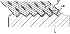
- the outer periphery of the magnetic cylindrical body 24 in which the rotary shaft 20 is press-fitted inside each of the inner peripheral edge portions 66, that is, the tip of the inner peripheral edge portion 66 is the magnetic outer peripheral portion of the rotary shaft 20. It is possible to set the diameter of the tip of the inner peripheral edge 66 so as to be in close contact with the surface. The close contact further reduces the magnetic resistance and stabilizes the positions of the first and second rotor cores with respect to the rotating shaft. The close contact here does not have to be exact. For example, as shown in FIG. 6A, even if there is actually a gap between the tip of the inner peripheral edge 66 and the outer peripheral surface of the magnetic cylindrical body 24, the magnetic resistance can be reduced if the gap is very small. is there. Furthermore, as shown in FIG. 6B, the magnetic resistance can be further reduced by providing the stepped portion 24a on the outer peripheral surface of the magnetic cylindrical body 24 in accordance with the arrangement of the inner peripheral edge portions 66.
- a taper corresponding to the inner peripheral edge 66 is given to the outer peripheral surface 26 a of each pressing jig 26. This enables the pressing jig 26 to restrain the rotor cores 30A and 30B from both outsides in the axial direction.
- the first and second rotor cores 30A, 30B are constituted by a plurality of unit plates 60 stacked in the axial direction, and therefore the rotor core 30A,
- the rotor cores 30A and 30B having excellent eddy current prevention characteristics can be easily constructed without requiring a complicated fastening structure and a large number of assembly parts. It is possible.
- this generator can be efficiently manufactured by the following procedure.
- each unit plate 60 is a single flat plate made of a magnetic material, and an original plate including the substrate portion 62 and the magnetic pole plate portions 64 is prepared and bent (for example, It can be easily formed by press forging.
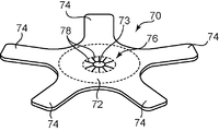
- the original plate 70 shown in FIG. 4A includes a central circular portion 72 corresponding to the substrate portion 62, and a plurality of petal-like portions 74 corresponding to the magnetic pole plate portions 64 and extending radially from the portion 62 ′.
- a circular through hole 73 is formed at the center of the circular portion 72.
- a peripheral edge portion 76 that surrounds the through hole 73 in the circular portion 72 is divided in the circumferential direction by radial slits 78.
- the original plate 70 can be easily punched out of a normal plate material.
- the original plate 70 is press-forged so that the petal-like portion 74 and the divided through-hole peripheral portion 76 are bent to the same side, whereby a cup-shaped unit plate 60 as shown in FIGS. 4B and 4B. Can be formed.
- the circular portion 72, the petal-like portions 74, and the divided peripheral portion 76 constitute a substrate portion 62, magnetic pole plate portions 64, and an inner peripheral portion 66, respectively.
- each unit plate 60 As the material of each unit plate 60, a material that has excellent magnetic properties (saturation magnetic flux density, magnetic permeability) and forging workability and can be obtained at a lower cost than electromagnetic steel plates, that is, an industrially advantageous material is used. It is preferable to use it.
- a pure iron material is suitable.
- impurity elements harmful to magnetic properties such as C, P, S, and the concentration of these impurities are carbon (C) 300 ppm or less, phosphorus (P) 300 ppm or less, and sulfur (S) 300 ppm or less. It is an iron-based alloy, and it is preferable that at least one of both side surfaces and the cut end surface are covered with an insulating coating.
- C is preferably 200 ppm or less, more preferably 100 ppm or less
- P is preferably 200 ppm or less, more preferably 150 ppm or less.
- the element Al effective for deoxidation in the steelmaking process is an element effective for fixing N and an element necessary for controlling the form of inclusions. 0.03% or less (excluding 0%) is preferable.
- the following permissible components can be added as long as the effects of the present invention are not impaired.
- the total amount of the impurity elements is preferably 0.05% or less (excluding 0%).
- Elements of Cr, Cu, Sn, Ni, Mo, Nb, V, B, N are also elements that have an effect of improving the deformability of steel.
- the total amount of these impurity elements is: It is desirable that it is not less than 0.05%.
- the magnetic flux density at an exciting magnetic field of 10000 A / m is pure iron or an iron alloy having a magnetic flux density of 1.5 T or more.
- preferred component compositions are exemplified below.
- Concentrations of impurity elements C, P, S and Al harmful to magnetic properties are C: 0.03% or less, P: 0.03% or less, S: 0.03%, Al: 0.03% The remainder consists of iron and inevitable impurities.
- Concentrations of impurity elements C, P, S and Al harmful to magnetic properties are C: 0.03% or less, P: 0.03% or less, S: 0.03%, Al: 0.03%
- concentration of Mn is 0.10 to 0.50, and the balance consists of iron and inevitable impurities.
- Concentrations of impurity elements C, P, S and Al harmful to magnetic properties are C: 0.03% or less, P: 0.03% or less, S: 0.03%, Al: 0.03%
- concentration of Mn is 0.10 to 0.50%
- concentration of Si is 0.05 to 2.0%
- the balance has a component composition consisting of iron and inevitable impurities.
- the thin plate material used for the unit plate 60 is manufactured by cold rolling, desired magnetic properties cannot be obtained as they are, so that the temperature at which the magnetic properties can be recovered (generally 850 ° C.).
- So-called magnetic annealing is preferably performed. This magnetic annealing improves magnetic properties such as saturation magnetic flux density by growing crystal grains.
- the size of the crystal grains is preferably an average crystal grain size of 100 ⁇ m or more, whereby excellent magnetic properties can be obtained.
- the first and second rotor cores 30A and 30B are constructed by laminating a predetermined number of unit plates 60 in the axial direction. At this time, the substrate portions 62 of the unit plates 60 are laminated in the axial direction to form the base portion 32 of the rotor cores 30A and 30B, and the magnetic pole plate portions 64 are laminated in the axial direction of the rotor cores. Part 34 is configured. Further, the inner peripheral edge portions 66 of the unit plates 60 are also laminated in the axial direction to stabilize the laminated state of the entire unit plate 60. With this lamination, the tip 65 of each petal-shaped magnetic pole plate portion 64 is aligned in the axial direction to form a rotor magnetic pole surface.
- the rotor magnetic pole surface is a surface that can be opposed to the stator magnetic pole surface in a posture parallel to the stator magnetic pole surface by the subsequent insertion of the rotor into the casing 50.
- the magnetic pole plate portions 64 and the inner peripheral edge portions 66 that are adjacent to each other are in contact with or close to each other, whereas the portions of the substrate portion 62 that are located radially outside the inner peripheral edge portion 66.
- a gap in the axial direction remains in between, and the gap becomes larger as the angle of the radially outward inclination of the magnetic pole plate portion 64 becomes smaller.
- the magnetic annular body 36 made of a magnetic material between the substrate portions 62 so as to fill the gap, the magnetic resistance in the rotor cores 30A and 30B can be effectively utilized by using the gap. It is possible to reduce.
- the unit plates 60 be integrated by impregnation with an appropriate resin, that is, the rotor cores 30A and 30B are performed. This integration significantly facilitates the next assembly process.
- the rotor coil 40 is disposed between the magnetic pole plate portion 64 and the inner peripheral edge portion 66 of the innermost unit plate 60 among the unit plates 60 constituting the rotor cores 30A and 30B.
- the inner surface of the rotor coil 40 and the inner peripheral edge 66 in other words, between the rotor coil 40 and the rotating shaft 20
- the outer surface of the rotor coil 40, and the magnetic pole plate 64 It is preferable that an inner spacer 81 and an outer spacer 82 as shown in FIG. Both of these spacers 81 and 82 have an annular shape surrounding the rotary shaft 20.
- the inner side surface of the inner spacer 81 has a first taper surface 81a and a second taper surface 81b, each of which is provided with an inclination corresponding to the inner peripheral edge 66 of the unit plate 60 constituting both rotor cores 30A and 30B.
- the outer peripheral surface of the outer spacer 82 has a first tapered surface 82a provided with an inclination corresponding to the magnetic pole plate portion 64 of the unit plate 60 of the first rotor core 30A, and the unit plate 60 of the second rotor core 30B.
- the second tapered surface 82b corresponding to the magnetic pole plate portion 64 is included, and these tapered surfaces 82a and 82b are alternately arranged in the circumferential direction. Both the spacers 81 and 82 can stabilize the position of the rotor coil 40 and can also stabilize the positions of both rotor cores 30A and 30B in the axial direction.
- the holding jigs 26 are mounted on both ends of the main body shaft 22 in the axial direction, and both outer sides thereof.
- a fixing nut 28 is attached to the.
- the magnetic cylindrical body 24 is sandwiched between the pressing jigs 26, and the rotor core 30A is sandwiched between the rotor coil 40 and the spacers 81 and 82 in the center.
- 30B are restrained from both outsides in the axial direction.
- the whole rotor assembled in this way is inserted inside the stator 10 in the casing 50, whereby the generator is completed.
- the present invention is not limited to the embodiment described above.
- the magnetic annular body 36 and the spacers 81 and 82 can be omitted as appropriate according to specifications, and appropriate changes and improvements can be made.
- each magnetic pole plate portion 64 may be bent to form a hook-like portion 67 that protrudes radially outward toward the stator magnetic pole surface.
- These hook-shaped portions 67 facilitate the penetration of magnetic flux lines from the rotor magnetic pole portion 34 to the stator magnetic pole, thereby enabling improvement in power generation performance or electric performance and further suppression of eddy currents.
- At least one of the unit plates 60 constituting each of the rotor cores 30A and 30B is annular on the outer unit plate located on the outermost side in the axial direction (leftmost in FIG. 7). More preferably, the restraining member 84 is attached.
- the restraining member 84 is made of a high-tensile material and is mounted so as to straddle the magnetic pole plate portions 64 of the outer unit plate, so that the magnetic pole plate portions 64 spread radially outward by centrifugal force. Stop.
- the restraining member 84 can effectively suppress deformation of each magnetic pole plate portion due to centrifugal force with a simple structure.
- the rotor cores 30A and 30B according to the first embodiment have a single base portion 32 and a plurality of rotor magnetic pole portions 34 connected thereto, whereas the rotor according to the second embodiment.
- Each of the iron cores 30A and 30B includes a plurality of divided base portions 32 ′ divided in the circumferential direction and a plurality of rotor magnetic pole portions 34 extending from the respective divided base portions 32 ′ along the axial direction.
- each rotor core 30A, 30B is constituted by a plurality of divided bodies 30 'divided in the circumferential direction, and each divided body 30' has a single divided base 32 'and a single rotor connected thereto.
- the magnetic pole part 34 is comprised.
- each divided body 30 'of each of the rotor cores 30A, 30B can be constituted by a plurality of unit plates 90 stacked on each other.
- Each unit plate 90 is composed of a single plate material made of a magnetic material, like the unit plate 60 according to the first embodiment, and includes a divided substrate portion 92 and an outer end portion of the divided substrate portion 92.
- a magnetic pole plate portion 94 that extends along the axial direction while inclining radially outward is integrally provided.
- the inner peripheral edge portion 96 of the divided substrate portion 92 extends on the same side as the magnetic pole plate portion 64 along the axial direction while being inclined inward in the radial direction.
- Each unit plate 90 can be formed by bending a flat original plate 90 ′ as shown in FIG.
- the original plate 90 ′ integrally includes a first portion 92 ′ corresponding to the divided substrate portion 92 and a second portion 94 ′ corresponding to the magnetic pole plate portion 94, and the second portion of the first portion 92 ′.
- An end 96 ′ opposite to 94 ′ corresponds to the inner peripheral edge 96. Therefore, the unit plate 90 can be formed by bending the second portion 94 'and the end portion 96' of the original plate 90 'by press forging or the like.
- the divided substrate portions 92 are laminated in the axial direction to form a divided base portion 32 ′ of each divided body 30 ′, and the magnetic pole plate portions 94 are laminated to each other to form the divided base portions 32 ′.
- the rotor magnetic pole portion 34 of the divided body 30 ′ is configured, and the inner peripheral edge portions 96 are also laminated in the axial direction along with the lamination.
- the stacked unit plates 90 are integrated by, for example, impregnation with resin, whereby a plurality of divided bodies 30 ′ constituting the rotor cores 30 ⁇ / b> A and 30 ⁇ / b> B are constructed.
- a divided annular body 36 ′ made of a magnetic material is interposed between the divided base portions 32 ′.
- the rotor cores 30A and 30B are formed by arranging and fixing the divided bodies 30 'constructed in this way around the rotary shaft 20.
- the fixing means is not particularly limited.
- a groove into which the inner peripheral edge 96 of each unit plate 90 can be inserted is formed in the outer peripheral surface of the rotating shaft 20 (the outer peripheral surface of the magnetic cylindrical body 24 in the figure).
- a spacer made of a nonmagnetic material is interposed between the divided bodies 30 ′ adjacent to each other in the circumferential direction.
- the spacer can be formed integrally with the holding jig 26 or the inner spacer 81 attached to both ends of the rotary shaft 20.
- the generator includes a plurality of stator cores each including a stator magnetic pole and arranged in a circumferential direction so as to surround a space inside, and a stator coil wound around the stator core; and A rotating shaft disposed inside the stator so as to be rotatable with respect to the stator and having a magnetic outer peripheral portion made of a magnetic material in at least a partial region in the axial direction, and the rotation inside the stator
- a first rotor core and a second rotor core disposed around the magnetic outer periphery so as to rotate together with a shaft, wherein each of the first rotor core and the second rotor core is A base portion arranged around the magnetic outer peripheral portion and a plurality of positions arranged in the circumferential direction on the outer periphery of the base portion extend along the axial direction of
- first and second rotor magnetic pole portions of the first rotor core and the rotor magnetic pole portions of the second rotor core are alternately arranged in the circumferential direction of rotation.
- a rotor coil that is provided on the radially inner side of the rotor magnetic pole portion of the rotor core and generates magnetic flux in each of the rotor cores and the stator core.
- the first and second rotor cores are constituted by a plurality of unit plates that are stacked along the axial direction of the rotating shaft while being electrically insulated from each other.
- Each unit plate is composed of a single thin plate made of a magnetic material, and has a through hole in the center and is arranged around the magnetic outer peripheral portion of the rotary shaft in a state where the rotary shaft is inserted through the through hole. And a plurality of magnetic pole plate portions extending along the axial direction of the rotating shaft while being inclined radially outward from a plurality of positions arranged in the circumferential direction on the outer periphery of the substrate portion.
- Each of the substrate portions constitutes a base portion of the first and second rotor cores by being laminated in the axial direction, and each of the magnetic pole plate portions is laminated in the axial direction.
- Each of the rotor magnetic pole portions of the two-rotor core is configured.
- each rotor core is composed of a single iron block as in the prior art.
- each unit plate is composed of a single thin plate made of a magnetic material so as to integrally have a substrate portion and a plurality of magnetic pole plate portions, and each substrate portion and each magnetic pole plate portion are laminated in the axial direction.
- the first and second rotor iron cores and the rotor magnetic pole part are respectively configured. Therefore, an excellent eddy current prevention characteristic can be obtained without requiring a complicated fastening structure and a large number of assembly parts.
- a rotor iron core is built.
- each unit plate can have the same shape, and thereby the production efficiency of each rotor core is dramatically increased.
- the unit plates are arranged so that the tips of the magnetic pole plates of the unit plates are aligned along the stator magnetic pole surface, which is the inner surface of the stator magnetic poles, by stacking the unit plates in the axial direction.
- the stator magnetic pole surface which is the inner surface of the stator magnetic poles
- Such a rotor magnetic pole surface effectively suppresses the generation of eddy currents while allowing a smooth magnetic flux to enter from the stator magnetic pole surface.
- each magnetic pole plate portion forms a hook-like portion that protrudes radially outward toward the stator magnetic pole surface, the flow of magnetic flux becomes smoother.
- the portion surrounding the through hole in the substrate portion of each unit plate constitutes an inner peripheral edge extending in the same direction as the magnetic pole plate while being inclined inward in the radial direction, and these inner peripheral edges are in the axial direction. More preferably, they are stacked on each other. By laminating these inner peripheral edges, the laminated state of the unit plates is more stable. In addition, the inclination of each inner peripheral edge can increase the opposing area of the both, compared with the case where the peripheral edge is orthogonal to the rotation axis, for example, thereby reducing the magnetic resistance.
- the diameter of the tip of the inner peripheral edge is set so that the tip of each inner peripheral edge is in close contact with the outer peripheral surface of the magnetic outer peripheral portion of the rotating shaft, whereby the inner peripheral edge and the The magnetic resistance between the magnetic outer peripheral portion can be further reduced, and the positions of the first and second rotor cores with respect to the rotating shaft can be stabilized.
- Each unit plate according to the present invention can be easily formed by bending (for example, press forging) a single flat plate made of a magnetic material including the substrate portion and the magnetic pole plate portions. Is possible.
- Each unit plate is preferably magnetically annealed in order to exhibit excellent magnetic properties.
- a thin iron plate having a ferrite single-phase metal structure, which is annealed at 850 ° C. or higher so that the average crystal grain size is 100 ⁇ m or more is preferable.
- each unit plate it is preferable that at least one side surface and end surface of both side surfaces are covered with an insulating film.
- the specific material of each unit plate is a material having good magnetic characteristics, specifically, pure iron or an iron alloy having a magnetic flux density of 1.5 T or more at an excitation magnetic field of 10000 A / m. It is preferable.
- an iron-based material having a component composition that satisfies one of the following conditions (excluding the insulating coating) is suitable.
- Concentrations of impurity elements C, P, S and Al harmful to magnetic properties are C: 0.03% or less, P: 0.03% or less, S: 0.03%, Al: 0.03% The remainder consists of iron and inevitable impurities.
- Concentrations of impurity elements C, P, S and Al harmful to magnetic properties are C: 0.03% or less, P: 0.03% or less, S: 0.03%, Al: 0.03%
- concentration of Mn is 0.10 to 0.50, and the balance consists of iron and inevitable impurities.
- Concentrations of impurity elements C, P, S and Al harmful to magnetic properties are C: 0.03% or less, P: 0.03% or less, S: 0.03%, Al: 0.03%
- concentration of Mn is 0.10 to 0.50%
- concentration of Si is 0.05 to 2.0%
- the balance has a component composition consisting of iron and inevitable impurities.
- each unit plate is determined by multiplying the generator rotation frequency (rated rotation frequency) by the number of rotor magnetic poles of each rotor core, and the material (conductivity and permeability) of the rotor core. It is preferable that the skin depth value is equal to or less than the skin depth value corresponding to 10 times the magnetic pole frequency.
- the rotating shaft is made of, for example, a main body shaft and a magnetic material, and is arranged around the main body shaft in at least a partial region in the axial direction of the main body shaft to constitute the magnetic outer peripheral portion.
- the one containing the body is preferred.
- the generator according to the present invention further includes an outer spacer and an inner spacer made of a nonmagnetic insulating material, and the outer spacer is interposed between the rotor magnetic pole portion of each rotor core and the rotor coil. It is preferable that the inner spacer is interposed between the rotor coil and the rotating shaft. These spacers can stabilize the position of the rotor coil and each rotor magnetic pole part with respect to the rotating shaft.
- each magnetic pole plate portion of the outer unit plate located at the most axially outer side among the unit plates constituting each of the rotor cores is spread radially outward by centrifugal force. It is preferable to further include an annular restraining member that is mounted so as to straddle these magnetic pole plate portions so as to prevent the above.
- This constraining member has a simple structure and can effectively suppress deformation of each of the magnetic pole plate portions due to centrifugal force.
- each of the rotor cores is preferably made of a magnetic material, and further includes a magnetic annular body interposed between the substrate portions of the unit plates adjacent to each other.
- the interposition of the magnetic annular body makes it possible to reduce the magnetic resistance in the rotor core by effectively utilizing the axial gap formed between the substrate portions by stacking the unit plates.
- the base portion of the first and second rotor cores may be divided in the circumferential direction for each rotor magnetic pole portion. That is, each rotor core extends along the axial direction of the rotary shaft from a plurality of divided bases arranged around the magnetic outer peripheral part so as to be aligned in the circumferential direction, and the outer end of each base part, And a plurality of rotor magnetic pole portions that can be magnetically coupled to face the stator magnetic pole.
- the first and second rotor cores can be composed of a single thin plate made of a magnetic material, and can be composed of a plurality of unit plates that are stacked while being electrically insulated from each other. It is.
- Each unit plate in this case includes a divided substrate portion arranged around the magnetic outer periphery of the rotating shaft and an axial direction of the rotating shaft while being inclined radially outward from an outer end portion of the divided substrate portion.
- a plurality of magnetic pole plate portions extending along the same, and each divided substrate portion is laminated in the axial direction to constitute the divided base portions of the first and second rotor cores, respectively. What is necessary is just to respectively comprise the rotor magnetic pole part of the said 1st and 2nd rotor iron core by laminating
Landscapes
- Engineering & Computer Science (AREA)
- Power Engineering (AREA)
- Manufacturing & Machinery (AREA)
- Iron Core Of Rotating Electric Machines (AREA)
- Synchronous Machinery (AREA)
Priority Applications (3)
| Application Number | Priority Date | Filing Date | Title |
|---|---|---|---|
| CN201480034314.1A CN105308836B (zh) | 2013-06-20 | 2014-03-31 | 发电机 |
| EP14814610.3A EP3012948A4 (en) | 2013-06-20 | 2014-03-31 | Generator |
| US14/899,734 US10063114B2 (en) | 2013-06-20 | 2014-03-31 | Generator |
Applications Claiming Priority (2)
| Application Number | Priority Date | Filing Date | Title |
|---|---|---|---|
| JP2013-129186 | 2013-06-20 | ||
| JP2013129186A JP5662523B2 (ja) | 2013-06-20 | 2013-06-20 | 発電機 |
Publications (1)
| Publication Number | Publication Date |
|---|---|
| WO2014203437A1 true WO2014203437A1 (ja) | 2014-12-24 |
Family
ID=52104193
Family Applications (1)
| Application Number | Title | Priority Date | Filing Date |
|---|---|---|---|
| PCT/JP2014/001874 WO2014203437A1 (ja) | 2013-06-20 | 2014-03-31 | 発電機 |
Country Status (5)
| Country | Link |
|---|---|
| US (1) | US10063114B2 (zh) |
| EP (1) | EP3012948A4 (zh) |
| JP (1) | JP5662523B2 (zh) |
| CN (1) | CN105308836B (zh) |
| WO (1) | WO2014203437A1 (zh) |
Families Citing this family (2)
| Publication number | Priority date | Publication date | Assignee | Title |
|---|---|---|---|---|
| CN106487187B (zh) * | 2015-08-28 | 2020-11-10 | 德昌电机(深圳)有限公司 | 单相永磁电机及使用该电机的吹风机 |
| JP6597705B2 (ja) * | 2016-06-03 | 2019-10-30 | 株式会社デンソー | 回転電機 |
Citations (6)
| Publication number | Priority date | Publication date | Assignee | Title |
|---|---|---|---|---|
| US2243318A (en) * | 1937-11-01 | 1941-05-27 | Rawlings George William | Laminated magnetic element |
| DE19856526A1 (de) * | 1998-12-08 | 2000-06-15 | Schaefertoens Joern Heinrich | Elektrischer Generator vorzugsweise für die Verwendung als Lichtmaschine im Kraftfahrzeug |
| JP2009038843A (ja) * | 2007-07-31 | 2009-02-19 | Hitachi Ltd | 車両用交流発電機およびその製造方法 |
| WO2011040247A1 (ja) | 2009-09-30 | 2011-04-07 | 三菱電機株式会社 | ランデル型回転機 |
| US20110133595A1 (en) * | 2009-12-03 | 2011-06-09 | Unipoint Electric Mfg. Co., Ltd. | Alternator and method of manufacturing a rotor core thereof |
| JP2011120419A (ja) | 2009-12-07 | 2011-06-16 | Mitsubishi Electric Corp | 回転電機 |
Family Cites Families (11)
| Publication number | Priority date | Publication date | Assignee | Title |
|---|---|---|---|---|
| US3226581A (en) * | 1961-06-29 | 1965-12-28 | Motorola Inc | Generating system |
| US6121709A (en) * | 1997-10-16 | 2000-09-19 | Alliedsignal Inc. | Rotor assembly having bonded lamination stack |
| GB2338115B (en) | 1998-04-14 | 2002-08-07 | Gec Alsthom Ltd | Improvements in or relating to rotor cores for electrical rotating machines |
| DE19964061A1 (de) * | 1999-12-30 | 2001-07-05 | Bosch Gmbh Robert | Elektromotor, insbesondere für Handwerkzeugmaschinen |
| EP1330010A4 (en) * | 2000-09-01 | 2007-06-20 | Matsushita Electric Ind Co Ltd | ELECTRIC MOTOR |
| JP2002315284A (ja) * | 2001-04-06 | 2002-10-25 | Sawafuji Electric Co Ltd | オルタネータ |
| US20080315716A1 (en) * | 2007-06-20 | 2008-12-25 | Denso Corporation | Rotor for automotive alternator having mechanism for positioning magnetic pole cores |
| FR2930689B1 (fr) * | 2008-04-28 | 2010-04-16 | Schneider Electric Ind Sas | Machine tournante a flux transverse et dispositif de commutation equipe d'une telle machine |
| EP2299565B1 (de) * | 2009-09-17 | 2012-08-15 | Siemens Aktiengesellschaft | Kühlung eines Asynchronläufers |
| US8347485B2 (en) * | 2010-02-12 | 2013-01-08 | GM Global Technology Operations LLC | Centrifugally-cast shorted structure for induction motor rotors |
| CN103259353B (zh) * | 2012-02-15 | 2017-10-24 | 阿斯莫有限公司 | 转子以及电动机 |
-
2013
- 2013-06-20 JP JP2013129186A patent/JP5662523B2/ja not_active Expired - Fee Related
-
2014
- 2014-03-31 EP EP14814610.3A patent/EP3012948A4/en not_active Withdrawn
- 2014-03-31 US US14/899,734 patent/US10063114B2/en not_active Expired - Fee Related
- 2014-03-31 CN CN201480034314.1A patent/CN105308836B/zh not_active Expired - Fee Related
- 2014-03-31 WO PCT/JP2014/001874 patent/WO2014203437A1/ja active Application Filing
Patent Citations (6)
| Publication number | Priority date | Publication date | Assignee | Title |
|---|---|---|---|---|
| US2243318A (en) * | 1937-11-01 | 1941-05-27 | Rawlings George William | Laminated magnetic element |
| DE19856526A1 (de) * | 1998-12-08 | 2000-06-15 | Schaefertoens Joern Heinrich | Elektrischer Generator vorzugsweise für die Verwendung als Lichtmaschine im Kraftfahrzeug |
| JP2009038843A (ja) * | 2007-07-31 | 2009-02-19 | Hitachi Ltd | 車両用交流発電機およびその製造方法 |
| WO2011040247A1 (ja) | 2009-09-30 | 2011-04-07 | 三菱電機株式会社 | ランデル型回転機 |
| US20110133595A1 (en) * | 2009-12-03 | 2011-06-09 | Unipoint Electric Mfg. Co., Ltd. | Alternator and method of manufacturing a rotor core thereof |
| JP2011120419A (ja) | 2009-12-07 | 2011-06-16 | Mitsubishi Electric Corp | 回転電機 |
Non-Patent Citations (1)
| Title |
|---|
| See also references of EP3012948A4 * |
Also Published As
| Publication number | Publication date |
|---|---|
| JP5662523B2 (ja) | 2015-01-28 |
| CN105308836A (zh) | 2016-02-03 |
| US10063114B2 (en) | 2018-08-28 |
| EP3012948A4 (en) | 2017-02-22 |
| JP2015006046A (ja) | 2015-01-08 |
| US20160141922A1 (en) | 2016-05-19 |
| CN105308836B (zh) | 2018-01-23 |
| EP3012948A1 (en) | 2016-04-27 |
Similar Documents
| Publication | Publication Date | Title |
|---|---|---|
| KR100807853B1 (ko) | 다이나모 일렉트릭 장치 | |
| US20080246362A1 (en) | Radial airgap, transverse flux machine | |
| AU2011303910B2 (en) | Rotor for modulated pole machine | |
| US20040251761A1 (en) | Radial airgap, transverse flux motor | |
| WO2011122111A1 (ja) | 回転電機 | |
| JP2010239861A (ja) | 電気機器用の単一のアモルファス金属製部品を構築する方法 | |
| US9356498B2 (en) | Rotary electric machine with armature magnetic reaction compensation | |
| WO2017043601A1 (ja) | ステータコア、ステータコアを備えたモータ、これに用いられる電磁鋼板片及びその製造方法 | |
| WO2018037529A1 (ja) | 回転電機 | |
| JP2010017002A (ja) | 回転電機のステータコア | |
| JP5662523B2 (ja) | 発電機 | |
| US3513342A (en) | Rotor for alternating-current machines | |
| EP2319160B1 (de) | Hybriderregte elektrische maschine | |
| WO2011151138A2 (de) | Elektrische maschine mit reduzierter geräuschentwicklung | |
| JP6061832B2 (ja) | 回転電機およびその製造方法 | |
| WO2011104265A2 (de) | Elektrische maschine mit rotoreinrichtung und rotoreinrichtung mit optimiertem magnetfluss und verfahren zum betreiben der elektrischen maschine | |
| JP5894359B2 (ja) | ランデル型回転機 | |
| JP3161176B2 (ja) | 同期機のロータ構造および同期モータ | |
| JPH08275476A (ja) | 外転型永久磁石回転電機及び外転型永久磁石回転電機を用いた電動車両 | |
| Kokubo et al. | Design of dual rotor—Axial gap PMVM for hybrid electric vehicle | |
| JP2004222410A (ja) | モータのステータ鉄心 | |
| Hoffmann et al. | COFAT 2015-Load-oriented Topology with reduced material-needs and costs for electric car drives | |
| CN116780795A (zh) | 包括具有软磁复合材料部分和层压层的绝缘混合定子芯的轴向磁通电机 | |
| JP4123040B2 (ja) | 高効率回転機 | |
| JP2007104800A (ja) | 車両用回転電機 |
Legal Events
| Date | Code | Title | Description |
|---|---|---|---|
| WWE | Wipo information: entry into national phase |
Ref document number: 201480034314.1 Country of ref document: CN |
|
| 121 | Ep: the epo has been informed by wipo that ep was designated in this application |
Ref document number: 14814610 Country of ref document: EP Kind code of ref document: A1 |
|
| WWE | Wipo information: entry into national phase |
Ref document number: 14899734 Country of ref document: US |
|
| WWE | Wipo information: entry into national phase |
Ref document number: 2014814610 Country of ref document: EP |
|
| NENP | Non-entry into the national phase |
Ref country code: DE |