WO2014203294A1 - 波動歯車装置 - Google Patents
波動歯車装置 Download PDFInfo
- Publication number
- WO2014203294A1 WO2014203294A1 PCT/JP2013/003876 JP2013003876W WO2014203294A1 WO 2014203294 A1 WO2014203294 A1 WO 2014203294A1 JP 2013003876 W JP2013003876 W JP 2013003876W WO 2014203294 A1 WO2014203294 A1 WO 2014203294A1
- Authority
- WO
- WIPO (PCT)
- Prior art keywords
- boss
- bearing
- gear
- wave
- wave generator
- Prior art date
- Legal status (The legal status is an assumption and is not a legal conclusion. Google has not performed a legal analysis and makes no representation as to the accuracy of the status listed.)
- Ceased
Links
Images



Classifications
-
- F—MECHANICAL ENGINEERING; LIGHTING; HEATING; WEAPONS; BLASTING
- F16—ENGINEERING ELEMENTS AND UNITS; GENERAL MEASURES FOR PRODUCING AND MAINTAINING EFFECTIVE FUNCTIONING OF MACHINES OR INSTALLATIONS; THERMAL INSULATION IN GENERAL
- F16H—GEARING
- F16H49/00—Other gearings
- F16H49/001—Wave gearings, e.g. harmonic drive transmissions
-
- F—MECHANICAL ENGINEERING; LIGHTING; HEATING; WEAPONS; BLASTING
- F16—ENGINEERING ELEMENTS AND UNITS; GENERAL MEASURES FOR PRODUCING AND MAINTAINING EFFECTIVE FUNCTIONING OF MACHINES OR INSTALLATIONS; THERMAL INSULATION IN GENERAL
- F16C—SHAFTS; FLEXIBLE SHAFTS; ELEMENTS OR CRANKSHAFT MECHANISMS; ROTARY BODIES OTHER THAN GEARING ELEMENTS; BEARINGS
- F16C19/00—Bearings with rolling contact, for exclusively rotary movement
- F16C19/50—Other types of ball or roller bearings
-
- F—MECHANICAL ENGINEERING; LIGHTING; HEATING; WEAPONS; BLASTING
- F16—ENGINEERING ELEMENTS AND UNITS; GENERAL MEASURES FOR PRODUCING AND MAINTAINING EFFECTIVE FUNCTIONING OF MACHINES OR INSTALLATIONS; THERMAL INSULATION IN GENERAL
- F16C—SHAFTS; FLEXIBLE SHAFTS; ELEMENTS OR CRANKSHAFT MECHANISMS; ROTARY BODIES OTHER THAN GEARING ELEMENTS; BEARINGS
- F16C33/00—Parts of bearings; Special methods for making bearings or parts thereof
- F16C33/30—Parts of ball or roller bearings
- F16C33/58—Raceways; Race rings
- F16C33/583—Details of specific parts of races
- F16C33/586—Details of specific parts of races outside the space between the races, e.g. end faces or bore of inner ring
-
- F—MECHANICAL ENGINEERING; LIGHTING; HEATING; WEAPONS; BLASTING
- F16—ENGINEERING ELEMENTS AND UNITS; GENERAL MEASURES FOR PRODUCING AND MAINTAINING EFFECTIVE FUNCTIONING OF MACHINES OR INSTALLATIONS; THERMAL INSULATION IN GENERAL
- F16C—SHAFTS; FLEXIBLE SHAFTS; ELEMENTS OR CRANKSHAFT MECHANISMS; ROTARY BODIES OTHER THAN GEARING ELEMENTS; BEARINGS
- F16C19/00—Bearings with rolling contact, for exclusively rotary movement
- F16C19/02—Bearings with rolling contact, for exclusively rotary movement with bearing balls essentially of the same size in one or more circular rows
- F16C19/04—Bearings with rolling contact, for exclusively rotary movement with bearing balls essentially of the same size in one or more circular rows for radial load mainly
- F16C19/06—Bearings with rolling contact, for exclusively rotary movement with bearing balls essentially of the same size in one or more circular rows for radial load mainly with a single row or balls
Definitions
- the present invention relates to a short-wavelength wave gear device including a cup-shaped flexible external gear, and more particularly to a short-wavelength hollow wave gear device including a device hollow portion penetrating in the axial direction.
- Patent Document 1 describes an actuator having a configuration in which a hollow wave gear reducer including a cup-shaped flexible external gear and a hollow motor are integrally formed in the axial direction.
- a wave generator of a wave gear reducer described in Patent Document 1 includes an elliptically contoured cam plate (plug) integrally formed on an outer peripheral surface portion located inside a flexible external gear on a hollow rotating shaft. And a wave bearing (wave generator bearing) mounted on the elliptical outer peripheral surface of the cam plate.
- An annular retainer pressing plate is integrally formed on the rotating shaft at a position adjacent to the cam plate forming portion. By this retainer pressing plate, the retainer of the wave bearing is prevented from coming off in the direction of the rotation center axis. Furthermore, the shaft end portion of the rotating shaft located on the boss side of the flexible external gear is supported from the outer peripheral side by a bearing attached to a bearing holder attached to the boss.
- the shaft end portion (the shaft end portion of the rotating shaft) of the wave generator located inside the flexible external gear is a flexible external tooth. It is supported by a bearing mounted on a bearing holder attached to the gear boss. Since the bearing holder, the bearing, the retainer pressing plate, and the wave generator are arranged in the axial direction inside the flexible external gear, there is a limit to shortening the shaft length.
- an object of the present invention is to propose a wave gear device having a short axial length provided with a cup-shaped flexible external gear.
- the wave gear device of the present invention is: A rigid internal gear, A cup-shaped flexible external gear disposed inside the rigid internal gear and capable of meshing with the rigid internal gear; A wave generator disposed inside the flexible external gear and bending the flexible external gear in an elliptical shape to partially mesh with the rigid internal gear; A boss defining a central portion of the cup bottom surface of the flexible external gear; A bearing holder disposed inside the flexible external gear and fixed to the boss; A boss-side bearing mounted on the bearing holder and supporting the shaft end of the wave generator located on the boss side in a rotatable state from the outer peripheral side; A retainer pressing portion formed on a holder end surface facing the wave generator side in the bearing holder, and facing the retainer of the wave generator bearing of the wave generator at a predetermined interval; It is characterized by having.
- the shaft end portion of the wave generator located inside the cup-shaped flexible external gear has a boss-side bearing attached to a bearing holder attached to the boss of the flexible external gear. Is supported by.
- the bearing holder has a retainer pressing portion formed on the end face of the holder, and functions as a retainer pressing for the wave generator bearing. Therefore, it is not necessary to arrange the retainer pressing plate of the wave generator bearing inside the flexible external gear, and the axial length of the wave gear device can be shortened accordingly.
- the present invention can be applied to a hollow wave gear device having a device hollow portion penetrating in the device axial direction.
- the wave generator includes a hollow rotary shaft, a plug integrally formed on the outer peripheral surface of the hollow rotary shaft, and the wave generator bearing attached to the elliptical outer peripheral surface of the plug,
- the shaft end of the wave generator is a boss side shaft end located on the boss side of the hollow rotating shaft,
- the boss of the flexible external gear is an annular boss,
- the bearing housing includes an annular boss fixing portion fixed to a central through hole of the boss, The central through hole of the boss fixing portion and the hollow portion of the hollow rotary shaft are arranged coaxially to form a device hollow portion penetrating in the device axial direction.
- the wave gear device of the present invention is A first end plate fixed to the rigid internal gear; A second end plate fixed to the outer peripheral surface of the boss of the flexible external gear; An apparatus bearing supporting the rigid internal gear and the second end plate in a relatively rotatable state; It is attached to the inner peripheral surface of the central through hole formed in the first end plate, and supports the shaft end portion on the opposite side of the boss side shaft end portion of the hollow rotary shaft in a rotatable state from the outer peripheral side. Bearings, have.
- the rigid internal gear and the first end plate are formed from a single component from the viewpoint of reducing the number of parts, the number of assembly steps, and the like, and the one bearing ring of the device bearing and the second It is desirable to form the end plate from a single piece.
- the rigid internal gear, the first end plate, and the other bearing ring of the device bearing may be formed from a single component.
- FIG. 3 is a cross-sectional view of a portion cut along line III-III in FIG. 1. It is a half sectional view showing a hollow wave gear unit in which a retainer that does not require retainer pressing is arranged.
- FIG. 5 is a half cross-sectional view showing a hollow wave gear unit in which a seal member is arranged in a radial direction.
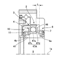
- FIG. 1 is a longitudinal sectional view of a wave gear unit according to the present embodiment
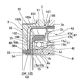
- FIG. 2 is a partially enlarged sectional view showing a part of the wave gear unit
- FIG. 3 is cut along a line III-III in FIG. It is a cross-sectional view of a part.
- the hollow wave gear unit 1 (overall structure)
- the hollow wave gear unit 1 (hereinafter sometimes simply referred to as “wave gear unit 1”) includes an annular rigid internal gear 2 having a rectangular cross section.
- a cup-shaped flexible external gear 3 is coaxially arranged inside the rigid internal gear 2.
- a wave generator 4 is disposed that bends the flexible external gear 3 in an elliptical shape and partially meshes with the rigid internal gear 2.
- the wave gear unit 1 is formed with a unit hollow portion 5 extending through the central portion in the direction of the axis 1a.
- a disc-shaped first unit end plate 6 is integrally formed on one end face 2 a of the rigid internal gear 2. It is also possible to fasten and fix these portions 2 and 6 as separate members.
- the first unit end plate 6 extends in a direction orthogonal to the axis 1a.
- a first bearing 7 is mounted on the inner peripheral surface of the central through hole of the first unit end plate 6, and one first shaft end 4 a of the wave generator 4 is supported by the first bearing 7 in a rotatable state. ing.
- a cross roller bearing 8 On the other end face 2b side of the rigid internal gear 2, a cross roller bearing 8 as a unit bearing is disposed adjacently.
- the outer ring 8a of the cross roller bearing 8 is formed integrally with the end face 2b of the rigid internal gear 2. It is also possible to fasten and fix these portions 2 and 8a as separate members.
- a disc-shaped second unit end plate 9 is integrally formed on the end surface of the inner ring 8 b of the cross roller bearing 8 opposite to the rigid internal gear 2. It is also possible to fasten and fix these portions 9 and 8b as separate members.
- the second unit end plate 9 extends in a direction orthogonal to the axis 1a, and is fixed to the outer peripheral surface of an annular boss 33 that defines the center portion of the cup bottom surface of the cup-shaped flexible external gear 3. Yes.
- the bearing holder 10 fixed to the boss 33 is disposed inside the flexible external gear 3.
- a second bearing 11 is mounted on the bearing holder 10. By the second bearing 11, the second shaft end 4 b on the boss 33 side in the wave generator 4 is supported in a rotatable state.
- the rigid internal gear 2 is fastened and fixed to a fixed side member (not shown), the first shaft end 4a of the wave generator 4 is connected to a high-speed rotation shaft such as a motor shaft (not shown), and a flexible external tooth
- the second unit end plate 9 fixed to the gear 3 is fastened to a driven side member (not shown).
- a part in which the rigid internal gear 2, the first unit end plate 6 and the outer ring 8 a of the cross roller bearing 8 are integrally formed becomes a unit housing 12 on the stationary side of the wave gear unit 1.
- a part in which the inner ring 8 b of the cross roller bearing 8 and the second unit end plate 9 are integrally formed becomes a unit housing 13 on the rotation side of the wave gear unit 1.
- the meshing position of the external teeth 3a of the flexible external gear 3 with respect to the internal teeth 2c of the rigid internal gear 2 moves in the circumferential direction.
- the wave generator 4 includes a hollow rotating shaft 41, a plug 42 having an elliptical contour formed integrally with the outer peripheral surface of the hollow rotating shaft 41, and a wave generator attached to the elliptical outer peripheral surface of the plug 42. Instrument bearing 43.
- the hollow portion of the hollow rotating shaft 41 defines a wave generator-side hollow portion 5a having a circular cross section that extends through the wave generator 4 in the direction of the axis 1a.
- One shaft end of the hollow rotating shaft 41 is the first shaft end 4 a of the wave generator 4, and the other shaft end is the second shaft end 4 b of the wave generator 4.
- the second shaft end portion 4 b is a boss side shaft end portion located on the boss 33 side of the flexible external gear 3.
- the wave generator bearing 43 includes an inner ring 44 and an outer ring 45 that can be bent in the radial direction.
- a plurality of balls 46 are inserted into an annular track between the inner and outer rings 44 and 45 so as to be able to roll.
- the balls 46 are held at regular angular intervals in the circumferential direction by an annular retainer 47.
- the retainer 47 includes an annular plate 47a and a partition plate 47b extending perpendicularly (in the direction of the axis 1a) from the end surface of the annular plate 47a at a constant angular interval.
- a pocket for each ball 46 is formed between adjacent partition plates 47b.
- the retainer 47 is mounted between the inner and outer rings 44 and 45 along the direction of the axis 1a from the second unit end plate 9 side.
- the flexible external gear 3 includes a cylindrical body 31 that can be bent in the radial direction, a disk-shaped diaphragm 32 that extends radially inward from one end of the cylindrical body 31, and the diaphragm. And an annular boss 33 formed on the inner peripheral edge of 32. External teeth 3 a are formed on the outer peripheral surface portion of the other opening end of the cylindrical body portion 31.
- the boss 33 is fixed to the circular inner peripheral surface of the second unit end plate 9 with no gap by press fitting, bonding, welding or the like.
- the bearing holder 10 is fixed to the circular center through hole of the boss 33 from the side opposite to the second unit end plate 9 in a gap state by press fitting, bonding, welding or the like.
- the bearing holder 10 includes an annular boss fixing portion 101 (flange portion), a thin disc-shaped leaf spring portion 102 extending radially outward from the boss fixing portion 101, and a leaf spring portion 102.
- An annular holder main body 103 extending in the axial direction from the outer peripheral edge toward the first unit end plate 6 is provided.
- the boss fixing portion 101 has an L-shaped cross-sectional shape including an insertion portion 104 fixed to the circular inner peripheral surface 34 of the boss 33 and an annular portion 105 extending along the annular end surface 35 inside the boss 33. is doing.
- the second bearing 11 is held inside the holder main body 103.
- the boss fixing portion 101, the leaf spring portion 102, and the holder main body portion 103 are integrally formed products made of a single member.
- the leaf spring portion 102 has a spring property that can urge the holder main body portion 103 in the direction of the axis 1a.
- the holder main body 103 is formed with a circular inner peripheral surface 103a for mounting an outer ring.
- An outer ring receiving surface 103b made of an annular step surface having a constant width orthogonal to the axis 1a is formed at the end of the circular inner peripheral surface 103a on the second unit end plate 9 side.
- the outer ring receiving surface 103b is a surface facing the first unit end plate 6 side.
- An outer ring 11a of the second bearing 11 is mounted on the circular inner peripheral surface 103a, and an annular end surface thereof abuts on the outer ring receiving surface 103b.
- the leaf spring portion 102 extends in a direction orthogonal to the axis 1a.
- leaf spring portion 102 connects the end portion on the second unit end plate 9 side with respect to the outer ring receiving surface 103 b in the holder main body portion 103 and the outer peripheral surface of the annular portion 105 of the boss fixing portion 101. Yes.
- a circular outer peripheral surface 4c for mounting an inner ring is formed on the circular outer peripheral surface of the second shaft end portion 4b of the hollow rotary shaft 41.
- an inner ring receiving surface 4d composed of an annular step surface having a constant width orthogonal to the axis 1a is formed.
- the inner ring receiving surface 4d is a surface facing the second unit end plate 9 side.
- An inner ring 11b of the second bearing 11 is mounted on the circular outer peripheral surface 4c, and an annular end surface thereof abuts on the inner ring receiving surface 4d.
- the leaf spring portion 102 is slightly displaced toward the second unit end plate 9 along the axis 1a when the second bearing 11 is mounted. Due to the elastic restoring force in the axial direction of the leaf spring portion 102, the second bearing 11 is preloaded in the axial direction (the direction in which the inner ring 11b is pressed against the inner ring receiving surface 4d).
- the bearing mechanism that supports the second shaft end 4b of the hollow rotating shaft 41 in a rotatable state is configured using the bearing holder 10 having a preload function. It is not necessary to arrange a part that applies preload to the second bearing 11.
- a bearing mechanism having a preload function can be configured with a small number of parts, and the installation space in the axial direction can be reduced. Therefore, if the bearing mechanism of this example is used, the axial length of the hollow wave gear unit 1 can be shortened.
- the bearing holder 10 has a retainer pressing function for the wave generator bearing 43 in addition to the preload function. That is, as can be seen from FIG. 2, the holder main body portion 103 of the bearing holder 10 includes an annular holder end face 106 facing the wave generator bearing 43. The holder end face 106 is formed at a position facing the annular plate 47a of the retainer 47 of the wave generator bearing 43 from the direction of the axis 1a. An annular protrusion 107 that slightly protrudes toward the retainer 47 is formed at the outer peripheral portion of the holder end surface 106. The annular protrusion 107 faces the end face of the annular plate 47a of the retainer 47 at a minute interval.
- the retainer 47 When the retainer 47 is about to come off between the inner and outer rings 44 and 45 in the direction of the axis 1a, the retainer 47 hits the annular protrusion 107.
- the annular protrusion 107 functions as a retainer pressing portion. There is no need to dispose the retainer pressing plate of the wave generator bearing 43 inside the flexible external gear 3. Therefore, the axial length of the hollow wave gear unit 1 can be shortened.
- the retainer 47A in this case includes annular plates 47c and 47d located on both sides of the ball 46, and a partition plate 47e is formed between them. Accordingly, it is necessary to secure a space L in which the annular plate 47d is disposed between the wave generator 4 and the first unit end plate 6 in the direction of the axis 1a. Since this space is required, the axial length of the hollow wave gear unit 1 becomes longer, which is not preferable.
- the unit hollow portion 5 includes a wave generator-side hollow portion 5 a defined by the hollow portion of the hollow rotating shaft 41 of the wave generator 4 and an insertion portion of the bearing holder 10 fixed to the boss 33 of the flexible external gear 3.
- the boss side hollow portion 5b is defined by the central through hole 104. Therefore, an annular gap is formed on the inner peripheral surface of the unit hollow portion 5. This gap is sealed by an annular seal member 14 having a V-shaped cross section.
- the seal member 14 is mounted in a gap 15 formed between the boss fixing portion 101 of the bearing holder 10 and the second shaft end portion 4b of the wave generator 4.
- the gap 15 includes an annular gap portion 15a having a small width that opens on the circular inner peripheral surface of the unit hollow portion 5, and a wide annular gap portion 15b formed on the outer circumferential side.
- An annular seal member 14 is attached to the gap portion 15b. As a result, the gap 15 is sealed so that lubricating oil or the like does not leak into the unit hollow portion 5.
- the gap 15 having the minute gap portion 15a and the wide gap portion 15b is formed as follows.
- An end surface portion 108 (boss-side end surface) of the bearing holder 10 facing the wave generator 4 is a flat end surface orthogonal to the axis 1a.
- the end face on the wave generator 4 side facing the end face portion 108 is a shaft end face 48 of the second shaft end 4b.
- the shaft end surface 48 includes an annular inner peripheral side end surface 48 a and an annular outer peripheral side end surface 48 b that is recessed with respect to the end surface portion 108 of the bearing holder 10 in the direction of the axis 1 a from the inner peripheral side end surface 48 a.
- a wide annular gap portion 15b is formed between the outer peripheral side end surface 48b and the end surface portion 108 of the bearing holder 10.
- a gap 15a having a very small width is formed between the inner peripheral side end surface 48a and the end surface portion 108.
- the shaft end surface 48 of the second shaft end portion 4b of the hollow rotating shaft 41 is formed in a step shape, and the outer peripheral side end surface 48b is retracted in the direction of the axis 1a with respect to the inner peripheral side end surface 48a.
- a wide gap portion 15b for mounting the seal member is formed between the outer peripheral side end surface 48b and the end surface portion 108 on the side of the bearing holder 10 facing the outer peripheral side end surface 48b. Therefore, the seal member 14 can be disposed between the boss fixing portion 101 and the hollow rotating shaft 41 on the wave generator side along the direction of the axis 1a.
- the seal member 14 ⁇ / b> A includes an inner peripheral surface 109 of the insertion portion 104 of the boss fixing portion 101, and an outer peripheral surface portion 41 ⁇ / b> A of the shaft end portion 4 b of the hollow rotary shaft 41 inserted inside the It can be considered to be worn between That is, the seal member 14A is disposed between the insertion portion 104 of the boss fixing portion 101 and the shaft end portion 4b of the hollow rotating shaft 41 on the wave generator side along the radial direction.
- the inner diameter of the unit hollow portion 5 ⁇ / b> A is defined by the hollow diameter of the hollow rotary shaft 41 inserted inside the insertion portion 104 of the boss fixing portion 101. Therefore, it is not suitable for forming a unit hollow portion having a large inner diameter.
- the wave gear unit 1 of the present example shown in FIGS. 1 to 3 such a problem can be eliminated and the unit hollow portion 5 having a large inner diameter can be formed.
- the seal member 14 can be disposed with the same unit axial length as in the case where the seal member 14 is disposed in the radial direction shown in FIG. Therefore, according to this example, the hollow wave gear unit 1 having a short axial length and including the large unit hollow portion 5 can be realized by using the cup-shaped flexible external gear 3.
- the gap between the inner peripheral surface of the first unit end plate 6 and the outer peripheral surface of the first shaft end portion 4 a is attached to a portion outside the first bearing 7.
- the first oil seal 16 is sealed.
- the gap between the inner ring 8 b and the outer ring 8 a of the cross roller bearing 8 is sealed by an annular second oil seal 17.
Landscapes
- Engineering & Computer Science (AREA)
- General Engineering & Computer Science (AREA)
- Mechanical Engineering (AREA)
- Retarders (AREA)
Abstract
Description
剛性内歯歯車と、
前記剛性内歯歯車の内側に配置され、前記剛性内歯歯車にかみ合い可能なカップ形状の可撓性外歯歯車と、
前記可撓性外歯歯車の内側に配置され、当該可撓性外歯歯車を楕円状に撓めて前記剛性内歯歯車に部分的にかみ合わせている波動発生器と、
前記可撓性外歯歯車のカップ底面の中心部分を規定しているボスと、
前記可撓性外歯歯車の内側に配置され、前記ボスに固定された軸受ホルダーと、
前記軸受ホルダーに装着され、前記ボスの側に位置する前記波動発生器の軸端部を外周側から回転自在の状態で支持しているボス側軸受と、
前記軸受ホルダーにおける前記波動発生器の側を向くホルダー端面に形成され、前記波動発生器の波動発生器軸受のリテーナーに対して所定の間隔で対峙するリテーナー押さえ部と、
を有していることを特徴としている。
前記波動発生器は、中空回転軸と、当該中空回転軸の外周面に一体形成されたプラグと、当該プラグの楕円状外周面に装着された前記波動発生器軸受とを備え、
前記波動発生器の前記軸端部は、前記中空回転軸における前記ボスの側に位置するボス側軸端部であり、
前記可撓性外歯歯車の前記ボスは円環状のボスであり、
前記軸受ハウジングは、前記ボスの中心貫通穴に固定した円環状のボス固定部を備え、
前記ボス固定部の中心貫通穴と前記中空回転軸の中空部とが同軸に配列されて、装置軸線方向に貫通する装置中空部が形成される。
前記剛性内歯歯車に固定した第1端板と、
前記可撓性外歯歯車の前記ボスの外周面に固定した第2端板と、
前記剛性内歯歯車と前記第2端板を相対回転自在の状態で支持している装置軸受と、
前記第1端板に形成した中心貫通穴の内周面に装着され、前記中空回転軸における前記ボス側軸端部とは反対側の軸端部を外周側から回転自在の状態で支持している軸受と、
を有している。
中空型波動歯車ユニット1(以下、単に「波動歯車ユニット1」と称する場合もある。)は、矩形断面をした環状の剛性内歯歯車2を備えている。剛性内歯歯車2の内側には、カップ形状の可撓性外歯歯車3が同軸に配置されている。可撓性外歯歯車3の内側には、可撓性外歯歯車3を楕円状に撓めて剛性内歯歯車2に部分的にかみ合わせている波動発生器4が配置されている。また、波動歯車ユニット1には、その中心部分を軸線1aの方向に貫通して延びるユニット中空部5が形成されている。
軸受ホルダー10は、円環状のボス固定部101(フランジ部)と、ボス固定部101から半径方向の外方に延びている薄い厚さの円盤状の板ばね部102と、板ばね部102の外周縁部から第1ユニット端板6の方向に向けて軸線方向に延びる円環状のホルダー本体部103とを備えている。ボス固定部101は、ボス33の円形内周面34に固定されている挿入部104と、ボス33の内側の円環状端面35に沿って延びる円環部105とを備えたL形断面形状をしている。ホルダー本体部103の内側に第2軸受11が保持されている。これらのボス固定部101、板ばね部102およびホルダー本体部103は単一部材からなる一体形成品である。板ばね部102は、ホルダー本体部103を軸線1aの方向に付勢可能なばね性を備えている。
再び、図1、図2を参照して説明する。ユニット中空部5は、波動発生器4の中空回転軸41の中空部によって規定される波動発生器側中空部5aと、可撓性外歯歯車3のボス33に固定した軸受ホルダー10の挿入部104の中心貫通穴によって規定されるボス側中空部5bから構成される。したがって、ユニット中空部5の内周面には円環状の隙間ができる。この隙間は、V形断面をした円環状のシール部材14によってシールされている。
Claims (4)
- 剛性内歯歯車(2)と、
前記剛性内歯歯車(2)の内側に配置され、前記剛性内歯歯車(2)にかみ合い可能なカップ形状の可撓性外歯歯車(3)と、
前記可撓性外歯歯車(3)の内側に配置され、当該可撓性外歯歯車(3)を楕円状に撓めて前記剛性内歯歯車(2)に部分的にかみ合わせている波動発生器(4)と、
前記可撓性外歯歯車(3)のカップ底面の中心部分を規定しているボス(33)と、
前記可撓性外歯歯車(3)の内側に配置され、前記ボス(33)に固定された軸受ホルダー(10)と、
前記軸受ホルダー(10)に装着され、前記波動発生器(4)における前記ボス(33)の側の軸端部(4b)を外周側から回転自在の状態で支持しているボス側軸受(11)と、
前記軸受ホルダー(10)における前記波動発生器(4)の側を向くホルダー端面(106)に形成され、前記波動発生器(4)の波動発生器軸受(43)のリテーナー(47)に対して所定の間隔で対峙するリテーナー押さえ部(107)と、
を有していることを特徴とする波動歯車装置(1)。 - 前記波動発生器(4)は、中空回転軸(41)と、当該中空回転軸(41)の外周面に一体形成されたプラグ(42)と、当該プラグ(42)の楕円状外周面に装着された前記波動発生器軸受(43)とを備え、
前記波動発生器(4)の前記軸端部(4b)は、前記中空回転軸(41)における前記ボス(33)の側のボス側軸端部であり、
前記可撓性外歯歯車(3)の前記ボス(33)は円環状のボスであり、
前記軸受ホルダー(10)は、前記ボス(33)の中心貫通穴に固定した円環状のボス固定部(101)を備え、
前記ボス固定部(101)の中心貫通穴と前記中空回転軸(41)の中空部とが同軸に配列されて、装置軸線(1a)方向に貫通する装置中空部(5)が形成されている請求項1に記載の波動歯車装置(1)。 - 前記剛性内歯歯車(2)に固定した第1端板(6)と、
前記可撓性外歯歯車(3)の前記ボス(33)に固定した第2端板(9)と、
前記剛性内歯歯車(2)と前記第2端板(9)を相対回転自在の状態で支持している装置軸受(8)と、
前記第1端板(6)に形成した中心貫通穴の内周面に装着され、前記中空回転軸(41)における前記ボス側軸端部(4b)とは反対側の軸端部(4a)を外周側から回転自在の状態で支持している軸受(7)と、
を有している請求項2に記載の波動歯車装置(1)。 - 前記剛性内歯歯車(2)と前記第1端板(6)は単一の部品からなり、
前記装置軸受(8)の一方の軌道輪(8b)と前記第2端板(9)は単一の部品からなる請求項3に記載の波動歯車装置(1)。
Priority Applications (7)
| Application Number | Priority Date | Filing Date | Title |
|---|---|---|---|
| DE112013002257.5T DE112013002257T5 (de) | 2013-06-20 | 2013-06-20 | Verformungswellgetriebe |
| JP2014552423A JP5839525B2 (ja) | 2013-06-20 | 2013-06-20 | 波動歯車装置 |
| KR1020147031137A KR101646904B1 (ko) | 2013-06-20 | 2013-06-20 | 파동기어장치 |
| PCT/JP2013/003876 WO2014203294A1 (ja) | 2013-06-20 | 2013-06-20 | 波動歯車装置 |
| CN201380032291.6A CN104379966B (zh) | 2013-06-20 | 2013-06-20 | 波动齿轮装置 |
| US14/400,358 US9523421B2 (en) | 2013-06-20 | 2013-06-20 | Strain wave gearing |
| TW103118630A TWI609142B (zh) | 2013-06-20 | 2014-05-28 | Harmonic gear device |
Applications Claiming Priority (1)
| Application Number | Priority Date | Filing Date | Title |
|---|---|---|---|
| PCT/JP2013/003876 WO2014203294A1 (ja) | 2013-06-20 | 2013-06-20 | 波動歯車装置 |
Publications (1)
| Publication Number | Publication Date |
|---|---|
| WO2014203294A1 true WO2014203294A1 (ja) | 2014-12-24 |
Family
ID=52104066
Family Applications (1)
| Application Number | Title | Priority Date | Filing Date |
|---|---|---|---|
| PCT/JP2013/003876 Ceased WO2014203294A1 (ja) | 2013-06-20 | 2013-06-20 | 波動歯車装置 |
Country Status (7)
| Country | Link |
|---|---|
| US (1) | US9523421B2 (ja) |
| JP (1) | JP5839525B2 (ja) |
| KR (1) | KR101646904B1 (ja) |
| CN (1) | CN104379966B (ja) |
| DE (1) | DE112013002257T5 (ja) |
| TW (1) | TWI609142B (ja) |
| WO (1) | WO2014203294A1 (ja) |
Cited By (8)
| Publication number | Priority date | Publication date | Assignee | Title |
|---|---|---|---|---|
| WO2017094715A1 (ja) * | 2015-12-01 | 2017-06-08 | 日本電産シンポ株式会社 | 電動機付き減速機 |
| JP2017166549A (ja) * | 2016-03-15 | 2017-09-21 | 株式会社ハーモニック・ドライブ・システムズ | ユニットタイプの波動歯車装置 |
| WO2017203754A1 (ja) * | 2016-05-27 | 2017-11-30 | 日本電産株式会社 | アクチュエータ |
| US20200072338A1 (en) * | 2017-04-10 | 2020-03-05 | Harmonic Drive Systems Inc. | Silk hat-type strain wave gear device |
| JP2021042859A (ja) * | 2020-11-25 | 2021-03-18 | 日本電産シンポ株式会社 | 波動歯車減速機ユニット |
| RU2760076C1 (ru) * | 2020-06-29 | 2021-11-22 | Хармоник Драйв Системс Инк. | Блок волновой передачи |
| JP2024020996A (ja) * | 2022-08-02 | 2024-02-15 | 株式会社ハーモニック・ドライブ・システムズ | 波動歯車装置 |
| WO2025262863A1 (ja) * | 2024-06-19 | 2025-12-26 | 株式会社ハーモニック・ドライブ・システムズ | モータ用軸受構造、モータおよび回転アクチュエータ |
Families Citing this family (7)
| Publication number | Priority date | Publication date | Assignee | Title |
|---|---|---|---|---|
| US10006534B2 (en) * | 2013-06-20 | 2018-06-26 | Harmonic Drive Systems Inc. | Bearing holder, bearing mechanism, and strain wave gearing device |
| DE102016217055B4 (de) * | 2015-09-10 | 2023-08-24 | Schaeffler Technologies AG & Co. KG | Getriebe mit elastischem Zahnrad |
| ITUB20159913A1 (it) * | 2015-12-23 | 2017-06-23 | Paolo Bigini | Dispositivo di trasmissione del moto |
| JP2017227315A (ja) * | 2016-06-24 | 2017-12-28 | 日本電産シンポ株式会社 | 波動歯車減速機ユニット |
| JP6941936B2 (ja) * | 2016-12-05 | 2021-09-29 | 住友重機械工業株式会社 | 減速装置 |
| DE102019106330A1 (de) * | 2019-03-13 | 2020-09-17 | Schaeffler Technologies AG & Co. KG | Verstelleinheit für ein Verstellgetriebe und Verstellgetriebe |
| WO2020234945A1 (ja) * | 2019-05-17 | 2020-11-26 | 株式会社ハーモニック・ドライブ・システムズ | コロ軸受式波動発生器を備えた波動歯車装置 |
Citations (4)
| Publication number | Priority date | Publication date | Assignee | Title |
|---|---|---|---|---|
| JPH0291240U (ja) * | 1989-01-05 | 1990-07-19 | ||
| JPH02113048U (ja) * | 1989-02-27 | 1990-09-10 | ||
| JP2002243000A (ja) * | 2001-02-19 | 2002-08-28 | Harmonic Drive Syst Ind Co Ltd | 波動歯車減速機を備えたアクチュエータ |
| WO2010089796A1 (ja) * | 2009-02-03 | 2010-08-12 | 株式会社ハーモニック・ドライブ・システムズ | ギヤ付きモータアセンブリ |
Family Cites Families (12)
| Publication number | Priority date | Publication date | Assignee | Title |
|---|---|---|---|---|
| JPS60107622U (ja) * | 1983-12-27 | 1985-07-22 | 日本精工株式会社 | 調和駆動装置用保持器付き転がり軸受 |
| JP3768261B2 (ja) * | 1995-05-19 | 2006-04-19 | 株式会社ハーモニック・ドライブ・システムズ | 偏平型波動歯車装置 |
| JPH0953707A (ja) * | 1995-08-16 | 1997-02-25 | Harmonic Drive Syst Ind Co Ltd | 波動歯車装置のグリス供給機構 |
| JPH0989053A (ja) * | 1995-09-29 | 1997-03-31 | Harmonic Drive Syst Ind Co Ltd | 波動歯車装置 |
| JP4010520B2 (ja) * | 1997-08-29 | 2007-11-21 | 株式会社ハーモニック・ドライブ・システムズ | ユニット型撓み噛み合い式歯車装置 |
| JP2002339990A (ja) * | 2001-05-22 | 2002-11-27 | Harmonic Drive Syst Ind Co Ltd | 軽量ベアリングおよび波動歯車装置 |
| JP4999475B2 (ja) * | 2007-01-24 | 2012-08-15 | 株式会社ハーモニック・ドライブ・システムズ | フラット型波動歯車装置 |
| JP2009047264A (ja) * | 2007-08-21 | 2009-03-05 | Nabtesco Corp | 偏心揺動型歯車装置 |
| DE112011105253T5 (de) * | 2011-05-16 | 2014-02-13 | Harmonic Drive Systems Inc. | Einheitstyp-Wellgetriebe |
| KR101748177B1 (ko) * | 2011-07-29 | 2017-06-16 | 가부시키가이샤 하모닉 드라이브 시스템즈 | 복합 롤링 베어링부착 파동기어장치 |
| US8516983B2 (en) * | 2011-09-30 | 2013-08-27 | Delphi Technologies, Inc. | Harmonic drive camshaft phaser with a harmonic drive ring to prevent ball cage deflection |
| DE112012000394T5 (de) * | 2012-12-12 | 2014-08-28 | Harmonic Drive Systems Inc. | Wellgetriebeeinheit mit Eingangslagern |
-
2013
- 2013-06-20 CN CN201380032291.6A patent/CN104379966B/zh active Active
- 2013-06-20 US US14/400,358 patent/US9523421B2/en active Active
- 2013-06-20 JP JP2014552423A patent/JP5839525B2/ja active Active
- 2013-06-20 KR KR1020147031137A patent/KR101646904B1/ko active Active
- 2013-06-20 WO PCT/JP2013/003876 patent/WO2014203294A1/ja not_active Ceased
- 2013-06-20 DE DE112013002257.5T patent/DE112013002257T5/de not_active Withdrawn
-
2014
- 2014-05-28 TW TW103118630A patent/TWI609142B/zh active
Patent Citations (4)
| Publication number | Priority date | Publication date | Assignee | Title |
|---|---|---|---|---|
| JPH0291240U (ja) * | 1989-01-05 | 1990-07-19 | ||
| JPH02113048U (ja) * | 1989-02-27 | 1990-09-10 | ||
| JP2002243000A (ja) * | 2001-02-19 | 2002-08-28 | Harmonic Drive Syst Ind Co Ltd | 波動歯車減速機を備えたアクチュエータ |
| WO2010089796A1 (ja) * | 2009-02-03 | 2010-08-12 | 株式会社ハーモニック・ドライブ・システムズ | ギヤ付きモータアセンブリ |
Cited By (15)
| Publication number | Priority date | Publication date | Assignee | Title |
|---|---|---|---|---|
| US10612638B2 (en) | 2015-12-01 | 2020-04-07 | Nidec-Shimpo Corporation | Speed reducer with electric motor |
| JP2017101734A (ja) * | 2015-12-01 | 2017-06-08 | 日本電産シンポ株式会社 | 電動機付き減速機 |
| WO2017094715A1 (ja) * | 2015-12-01 | 2017-06-08 | 日本電産シンポ株式会社 | 電動機付き減速機 |
| JP2017166549A (ja) * | 2016-03-15 | 2017-09-21 | 株式会社ハーモニック・ドライブ・システムズ | ユニットタイプの波動歯車装置 |
| WO2017203754A1 (ja) * | 2016-05-27 | 2017-11-30 | 日本電産株式会社 | アクチュエータ |
| US10823278B2 (en) * | 2017-04-10 | 2020-11-03 | Harmonic Drive Systems Inc. | Silk hat-type strain wave gear device |
| US20200072338A1 (en) * | 2017-04-10 | 2020-03-05 | Harmonic Drive Systems Inc. | Silk hat-type strain wave gear device |
| RU2760076C1 (ru) * | 2020-06-29 | 2021-11-22 | Хармоник Драйв Системс Инк. | Блок волновой передачи |
| JP2022010593A (ja) * | 2020-06-29 | 2022-01-17 | 株式会社ハーモニック・ドライブ・システムズ | 波動歯車装置ユニット |
| TWI784435B (zh) * | 2020-06-29 | 2022-11-21 | 日商和諧驅動系統股份有限公司 | 諧波齒輪裝置單元 |
| JP2021042859A (ja) * | 2020-11-25 | 2021-03-18 | 日本電産シンポ株式会社 | 波動歯車減速機ユニット |
| JP7037619B2 (ja) | 2020-11-25 | 2022-03-16 | 日本電産シンポ株式会社 | 波動歯車減速機ユニット |
| JP2024020996A (ja) * | 2022-08-02 | 2024-02-15 | 株式会社ハーモニック・ドライブ・システムズ | 波動歯車装置 |
| JP7847926B2 (ja) | 2022-08-02 | 2026-04-20 | 株式会社ハーモニック・ドライブ・システムズ | 波動歯車装置 |
| WO2025262863A1 (ja) * | 2024-06-19 | 2025-12-26 | 株式会社ハーモニック・ドライブ・システムズ | モータ用軸受構造、モータおよび回転アクチュエータ |
Also Published As
| Publication number | Publication date |
|---|---|
| TW201520451A (zh) | 2015-06-01 |
| CN104379966B (zh) | 2017-03-08 |
| DE112013002257T5 (de) | 2015-07-09 |
| TWI609142B (zh) | 2017-12-21 |
| US20160109014A1 (en) | 2016-04-21 |
| JP5839525B2 (ja) | 2016-01-06 |
| US9523421B2 (en) | 2016-12-20 |
| JPWO2014203294A1 (ja) | 2017-02-23 |
| KR20150008867A (ko) | 2015-01-23 |
| CN104379966A (zh) | 2015-02-25 |
| KR101646904B1 (ko) | 2016-08-09 |
Similar Documents
| Publication | Publication Date | Title |
|---|---|---|
| JP5839525B2 (ja) | 波動歯車装置 | |
| JP5839524B2 (ja) | 中空型波動歯車ユニット | |
| JP6045694B2 (ja) | 軸受機構および波動歯車装置 | |
| CN103717940B (zh) | 带复合滚动轴承的内齿齿轮单元及波动齿轮装置 | |
| JP5467019B2 (ja) | 撓み噛合い式歯車装置 | |
| JP3187367U (ja) | カップ型波動歯車装置ユニット | |
| JP5968528B2 (ja) | 波動発生器および波動歯車装置 | |
| WO2015001582A1 (ja) | 中空型波動歯車装置 | |
| JP6220757B2 (ja) | 内接式遊星歯車装置 | |
| JP2019027519A (ja) | 波動歯車装置 | |
| JP6656755B2 (ja) | 扁平アクチュエータ | |
| JP2019019861A (ja) | 波動歯車装置 | |
| WO2024218967A1 (ja) | 波動歯車装置 |
Legal Events
| Date | Code | Title | Description |
|---|---|---|---|
| ENP | Entry into the national phase |
Ref document number: 2014552423 Country of ref document: JP Kind code of ref document: A |
|
| ENP | Entry into the national phase |
Ref document number: 20147031137 Country of ref document: KR Kind code of ref document: A |
|
| WWE | Wipo information: entry into national phase |
Ref document number: 14400358 Country of ref document: US |
|
| WWE | Wipo information: entry into national phase |
Ref document number: 112013002257 Country of ref document: DE Ref document number: 1120130022575 Country of ref document: DE |
|
| 121 | Ep: the epo has been informed by wipo that ep was designated in this application |
Ref document number: 13887167 Country of ref document: EP Kind code of ref document: A1 |
|
| 122 | Ep: pct application non-entry in european phase |
Ref document number: 13887167 Country of ref document: EP Kind code of ref document: A1 |