WO2014199894A1 - 液体ディスペンサ、及びそれを構成するコック操作部材、電力制御装置、液体ディスペンサ制御システム、並びにプログラム及び記録媒体 - Google Patents
液体ディスペンサ、及びそれを構成するコック操作部材、電力制御装置、液体ディスペンサ制御システム、並びにプログラム及び記録媒体 Download PDFInfo
- Publication number
- WO2014199894A1 WO2014199894A1 PCT/JP2014/064961 JP2014064961W WO2014199894A1 WO 2014199894 A1 WO2014199894 A1 WO 2014199894A1 JP 2014064961 W JP2014064961 W JP 2014064961W WO 2014199894 A1 WO2014199894 A1 WO 2014199894A1
- Authority
- WO
- WIPO (PCT)
- Prior art keywords
- cock
- power
- beer
- dispenser
- output
- Prior art date
- Legal status (The legal status is an assumption and is not a legal conclusion. Google has not performed a legal analysis and makes no representation as to the accuracy of the status listed.)
- Ceased
Links
Images



Classifications
-
- B—PERFORMING OPERATIONS; TRANSPORTING
- B67—OPENING, CLOSING OR CLEANING BOTTLES, JARS OR SIMILAR CONTAINERS; LIQUID HANDLING
- B67D—DISPENSING, DELIVERING OR TRANSFERRING LIQUIDS, NOT OTHERWISE PROVIDED FOR
- B67D1/00—Apparatus or devices for dispensing beverages on draught
- B67D1/08—Details
- B67D1/12—Flow or pressure control devices or systems, e.g. valves, gas pressure control, level control in storage containers
- B67D1/1202—Flow control, e.g. for controlling total amount or mixture ratio of liquids to be dispensed
-
- B—PERFORMING OPERATIONS; TRANSPORTING
- B67—OPENING, CLOSING OR CLEANING BOTTLES, JARS OR SIMILAR CONTAINERS; LIQUID HANDLING
- B67D—DISPENSING, DELIVERING OR TRANSFERRING LIQUIDS, NOT OTHERWISE PROVIDED FOR
- B67D1/00—Apparatus or devices for dispensing beverages on draught
- B67D1/0003—Apparatus or devices for dispensing beverages on draught the beverage being a single liquid
- B67D1/0004—Apparatus or devices for dispensing beverages on draught the beverage being a single liquid the beverage being stored in a container, e.g. bottle, cartridge, bag-in-box, bowl
-
- B—PERFORMING OPERATIONS; TRANSPORTING
- B67—OPENING, CLOSING OR CLEANING BOTTLES, JARS OR SIMILAR CONTAINERS; LIQUID HANDLING
- B67D—DISPENSING, DELIVERING OR TRANSFERRING LIQUIDS, NOT OTHERWISE PROVIDED FOR
- B67D1/00—Apparatus or devices for dispensing beverages on draught
- B67D1/04—Apparatus utilising compressed air or other gas acting directly or indirectly on beverages in storage containers
- B67D1/0406—Apparatus utilising compressed air or other gas acting directly or indirectly on beverages in storage containers with means for carbonating the beverage, or for maintaining its carbonation
-
- B—PERFORMING OPERATIONS; TRANSPORTING
- B67—OPENING, CLOSING OR CLEANING BOTTLES, JARS OR SIMILAR CONTAINERS; LIQUID HANDLING
- B67D—DISPENSING, DELIVERING OR TRANSFERRING LIQUIDS, NOT OTHERWISE PROVIDED FOR
- B67D1/00—Apparatus or devices for dispensing beverages on draught
- B67D1/08—Details
- B67D1/0857—Cooling arrangements
- B67D1/0858—Cooling arrangements using compression systems
- B67D1/0861—Cooling arrangements using compression systems the evaporator acting through an intermediate heat transfer means
- B67D1/0864—Cooling arrangements using compression systems the evaporator acting through an intermediate heat transfer means in the form of a cooling bath
-
- B—PERFORMING OPERATIONS; TRANSPORTING
- B67—OPENING, CLOSING OR CLEANING BOTTLES, JARS OR SIMILAR CONTAINERS; LIQUID HANDLING
- B67D—DISPENSING, DELIVERING OR TRANSFERRING LIQUIDS, NOT OTHERWISE PROVIDED FOR
- B67D1/00—Apparatus or devices for dispensing beverages on draught
- B67D1/08—Details
- B67D1/0878—Safety, warning or controlling devices
- B67D1/0882—Devices for controlling the dispensing conditions
- B67D1/0884—Means for controlling the parameters of the state of the liquid to be dispensed, e.g. temperature, pressure
-
- B—PERFORMING OPERATIONS; TRANSPORTING
- B67—OPENING, CLOSING OR CLEANING BOTTLES, JARS OR SIMILAR CONTAINERS; LIQUID HANDLING
- B67D—DISPENSING, DELIVERING OR TRANSFERRING LIQUIDS, NOT OTHERWISE PROVIDED FOR
- B67D1/00—Apparatus or devices for dispensing beverages on draught
- B67D1/08—Details
- B67D1/0888—Means comprising electronic circuitry (e.g. control panels, switching or controlling means)
-
- B—PERFORMING OPERATIONS; TRANSPORTING
- B67—OPENING, CLOSING OR CLEANING BOTTLES, JARS OR SIMILAR CONTAINERS; LIQUID HANDLING
- B67D—DISPENSING, DELIVERING OR TRANSFERRING LIQUIDS, NOT OTHERWISE PROVIDED FOR
- B67D1/00—Apparatus or devices for dispensing beverages on draught
- B67D1/08—Details
- B67D1/12—Flow or pressure control devices or systems, e.g. valves, gas pressure control, level control in storage containers
- B67D1/14—Reducing valves or control taps
- B67D1/1405—Control taps
- B67D1/1411—Means for controlling the build-up of foam in the container to be filled
Definitions
- the present invention relates to a liquid dispenser such as a beer server and its constituent members.
- liquid dispensers have been used in which beverages such as beer and soft drinks are cooled to a low temperature and poured into a container such as a mug through a cock.
- the liquid dispenser includes a water tank for storing cooling water, a refrigerant evaporation pipe and a beverage pipe arranged in the water tank, a stirring device for stirring the cooling water in the water tank, and a refrigeration unit.
- the refrigerant compressed and cooled by the refrigeration unit passes through the refrigerant evaporation tube. As the refrigerant evaporates inside the refrigerant evaporation pipe, the cooling water around the outside of the refrigerant evaporation pipe is cooled and further partially frozen.
- the beverage supplied from outside passes inside the beverage tube.
- the beverage is cooled by heat exchange with cooling water around the outside of the beverage pipe, and then poured out from the cock.
- the stirring device is for stirring the cooling water in the water tank in order to efficiently perform the heat exchange.
- Patent Documents 1 and 2 propose improvements for reducing power consumption with respect to the liquid dispenser having the above configuration.
- Patent Document 1 is a control circuit for controlling the operation of a drive motor of an agitator (agitator) in a liquid dispenser, and a low-speed circuit that rotates at a low speed with a small energization amount, and a high speed at a large energization amount.
- a high-speed circuit for rotating the apparatus is provided, and an proximity sensor for detecting a person approaching the front of the aircraft is provided.
- the proximity sensor detects a person standing on the front of the aircraft and operating the cock
- the drive motor control circuit switches to a high-speed circuit, and when the proximity sensor stops detecting a person, the drive motor control circuit Control is performed so as to switch to a low-speed circuit.
- Patent Document 2 discloses a technique similar to the technique disclosed in Patent Document 1.
- Patent Document 3 discloses a technique in which a detection switch is provided on the cock in order to detect the operation of the cock.
- sensing by the proximity sensor that is, sensing that a person has approached the front of the machine body is regarded as a beverage pouring operation, and the drive motor of the stirring device In other words, the control circuit is switched to a high-speed circuit.
- the control circuit of the drive motor may be unnecessarily switched to a high-speed circuit even though the beverage pouring operation is not performed. There is a problem that the reduction effect is not sufficient.
- the above modification tends to be complicated because the cock is provided with a detection switch. Therefore, it cannot be said that the above modification is suitable for applying to a liquid dispenser already used in a store or the like. Further, the above modification is not suitable when the design change around the cock is to be made as small as possible even when it is applied to the newly manufactured liquid dispenser at the design stage. In the following, the description will be made on the premise of the former modification, but the effect of the present invention is not exhibited only in the former modification, but also in the latter modification.
- the present invention has been made with the above points as an object.
- the purpose of the present invention is to accurately detect the cock operation required for improving the power consumption reduction effect of the liquid dispenser. It is to be realized by a modification that can be more easily applied to the structure.
- the cock operation member according to the present invention includes a detection unit that detects the movement of the cock operation member, an output unit that outputs a signal according to a detection result by the detection unit, and Is provided.
- the cock operating member is provided with detecting means for detecting the movement of the cock operating member and output means for outputting a signal corresponding to the detection result to the outside. Therefore, accurate detection of the cock operation can be realized by a simple modification by simply replacing the cock lever or the like provided in the existing liquid dispenser with the cock operating member.
- the present invention realizes the accurate detection of the cock operation necessary for improving the power consumption reduction effect of the liquid dispenser by a modification that can more easily be applied to the structure of the existing liquid dispenser. There is an effect that can be.
- FIG. 1 It is a figure which shows the structure of the beer dispenser which concerns on Embodiment 1 of this invention. It is a perspective view which shows the external appearance of the cock lever with which the beer dispenser of FIG. 1 is provided. It is a figure which shows inclination operation
- FIG. 2 It is a top view which shows the display content of the liquid crystal display with which the cock lever of FIG. 2 is provided. It is a figure which shows the structure of the beer dispenser provided with the some cock lever which concerns on Embodiment 2 of this invention. It is a figure which shows the state by which the some beer dispenser which concerns on Embodiment 2 of this invention is mutually arrange
- a beer dispenser (sometimes referred to as a “beer server”) which is an embodiment of the liquid dispenser of the present invention will be described.
- the beer dispenser is generally used in an environment where the temperature is 5 ° C. or higher and 40 ° C. or lower.
- the liquid dispenser of the present invention is not limited to a beer dispenser.
- the liquid to be handled may be drinking water, soft drinks, etc. in addition to beer.
- a beer dispenser is for cooling the beer which is a target object
- the liquid dispenser of this invention may be for heating or heat retaining a target object.
- each constituent requirement of the present invention is as follows.
- the cock operating member is the cock lever 47
- the detecting means is the acceleration sensor 12
- the output means is the wireless unit 13
- the display means is the liquid crystal display 14
- the input means is the wireless unit 23
- the power control means is the power control unit 22.
- the hollow tube corresponds to the beer cooling tube 43
- the liquid dispenser corresponds to the beer dispensers 4, 4a, and 4b.
- the beer dispenser 4 is connected via a tube 53 to a beer barrel 51 that stores beer.
- the beer barrel 51 is connected to a carbon dioxide gas cylinder 52 via another tube 54. Then, the beer stored in the beer barrel 51 is pushed out by the carbon dioxide gas supplied from the carbon dioxide gas cylinder 52 and supplied to the beer dispenser 4.
- FIG. 1 is a diagram showing a configuration of a beer dispenser 4 according to the present embodiment.
- the beer dispenser 4 includes a cock lever 47 and a main body 40.
- the beer stored in the beer barrel 51 is supplied to the beer dispenser 4 through the beer supply port Pin, cooled by a cooling mechanism described later, and then poured out from the beer outlet Pout and poured into the glass B or the like.
- the beer dispenser 4 is provided to the user.
- the cock lever 47 is provided near the beer outlet Pout. Then, the user adjusts the amount of beer dispensed from the beer dispenser 4 by operating the cock lever 47.
- the beer dispenser 4 is provided with a water tank 41 for storing cooling water in the upper stage thereof, and is disposed below the water tank 41 with an evaporation pipe P spirally provided inside the water tank 41, a compressor, a condenser, A refrigeration unit 42 composed of a cooling fan or the like for cooling the condenser is provided.
- the refrigerant circulates through the refrigeration unit 42 and the evaporation pipe P. The refrigerant evaporates when passing through the evaporation pipe P, and cools the cooling water stored in the water tank 41 by heat exchange. .
- the beer dispenser 4 has one end connected to the beer supply port Pin and the other end connected to the beer outlet Pout, and an intermediate portion thereof is spirally provided inside the evaporation pipe P inside the water tank 41.
- a beer cooling pipe 43 made of stainless steel is provided.
- the beer supplied from the beer supply port Pin is sent out from the lower side of the beer cooling pipe 43 to the upper side.
- the beer is cooled to a predetermined temperature by the cooling water while passing through the beer cooling pipe 43.
- the cooled beer is provided to the user via the beer spout Pout.
- the beer dispenser 4 is configured to freeze the cooling water around the evaporation pipe P, store a certain amount of ice (ice storage), and agitate the unfrozen cooling water.
- the temperature of the cooling water can be effectively suppressed by melting the ice. it can.
- Ice storage is realized by controlling the operation of the refrigeration unit 42. Specifically, by monitoring the energization state between the pair of electrodes 45 provided in the vicinity of the evaporation pipe P in the water tank 41, it is determined whether or not the electrodes are frozen. Operates the refrigeration unit 42 and stops the refrigeration unit 42 when it is frozen.
- the stirring device 44 includes a stirring blade 49 provided in the water tank 41, a stirring motor M (not shown) that rotates the stirring blade 49, and a stirring shaft 50 that transmits the rotation of the stirring motor M to the stirring blade 49. ing.
- FIG. 2 is a perspective view showing the appearance of the cock 46 and the cock lever 47 of the beer dispenser 4.
- the cock lever 47 includes a liquid crystal display (LCD) 14 and a button 16 which will be described later, and a cock (draft) provided in the vicinity of the beer outlet Pout protruding from the outer surface of the beer dispenser 4. (It is also called a cock or a tap.) It is attached to 46 and is for operating the opening / closing operation of the cock 46.
- LCD liquid crystal display
- button 16 which will be described later
- a cock (draft) provided in the vicinity of the beer outlet Pout protruding from the outer surface of the beer dispenser 4.
- It is also called a cock or a tap.
- the cock 46 pours beer when the cock lever 47 is tilted toward the front side F (Forward), and when the cock lever 47 is tilted toward the back side B (Back) Foam is discharged, and beer pouring and foam discharge are stopped in a neutral state (position of the central axis) without inclination.
- the attachment structure of the cock lever 47 to the cock 46 is such that a male screw is formed on one side and a female screw is formed on the other side, and the cock lever 47 is attached by screwing. Thereby, the cock lever 47 can be easily attached to and detached from the cock 46.
- the cock lever 47 is a lever type that is operated by a user.
- the cock lever 47 may be of a type in which a container such as a cup is pressed and operated, and the shape of the cock lever 47 may be a shape of a faucet handle.
- the cock lever 47 incorporates the cock lever substrate 1 shown in FIG.
- the cock lever substrate 1 includes a CPU 11, an acceleration sensor 12, a wireless unit 13, a liquid crystal display 14, an EEPROM (registered trademark) 15, a button 16, and a power source 17. Yes.
- the CPU 11 performs various processes on the cock lever substrate 1, and details of the processes will be described later.
- the acceleration sensor 12 detects the inclination of the cock lever 47 and outputs the detection result to the CPU 11 as an inclination detection signal.
- the wireless unit 13 transmits a signal based on an instruction from the CPU 11 as a radio signal, and receives a radio signal transmitted from the wireless unit 23 provided on the power control board 2 described later and transmits the signal to the CPU 11. is there.
- the wireless communication system used by the wireless unit 13 may be ZigBee (registered trademark; IEEE 80.5.4) or Bluetooth (registered trademark), but is not limited to this configuration.
- the CPU 11 and the wireless unit 13 may be integrated as one module.
- the CPU 21 and the wireless unit 23 may be integrated as one module.
- the display surface of the liquid crystal display 14 is exposed to the outside of the cock lever 47, and performs various displays for the user.
- the display content of the liquid crystal display 14 is as shown in FIG. 7, and details thereof will be described later.
- the EEPROM 15 is for storing various programs executed by the CPU 11, various parameters used in the processing of the CPU 11, and the like.
- the button 16 is used for switching the display of the liquid crystal display 14, resetting parameters stored in the EEPROM 15, and the like.
- the power source 17 is for supplying electric power to each element provided in the cock lever substrate 1, and is constituted by a battery. By adopting a battery as the power source 17, the power source 17 can be reduced in size and can be easily incorporated in the cock lever 47.
- this battery can operate each element provided on the cock lever substrate 1 for more than half a year.
- the power source 17 may be a power generation device that generates power by a temperature difference between a liquid (beer, cooling water, etc.) flowing through the beer dispenser 4 and the cock lever 47.
- a Peltier element can be used as the power generation device.
- the liquid flowing through the beer dispenser 4 continues to be cooled below a certain temperature.
- the cock lever 47 is warmed by the user's hand or outside air. Therefore, the liquid flowing through the beer dispenser 4 and the cock lever 47 have a temperature difference.
- the Peltier element can generate power using the temperature difference and supply the generated power to the cock lever substrate 1.
- the cock lever 47 does not require a power supply from a finite power source such as a battery or an external power source. Further, the cock lever 47 can operate semipermanently as long as the beer dispenser 4 operates.
- the cock lever board 1 performs wireless communication with the power control board 2 shown in FIG. As shown in FIG. 2, the power control board 2 is mounted in the main body 40 of the beer dispenser 4.
- the power control board 2 includes a CPU 21, a power control unit 22, a wireless unit 23, a light emitting diode (LED) 24, an EEPROM (registered trademark) 25, a button 26, a power input unit 27, And a power output unit 28.
- the CPU 21 performs various processes in the power control board 2, and details of the process will be described later.
- the power control unit 22 is for controlling conduction and non-conduction between the power input unit 27 and the power output unit 28 based on an instruction from the CPU 21. Note that the power control unit 22 may change the power transmitted from the power input unit 27 to the power output unit 28 in a stepwise manner.
- the power input unit 27 is a part that receives input of power supplied from the power supply unit 48 mounted on the beer dispenser 4. A part of the power input to the power input unit 27 is used to operate each element provided in the power control board 2, and the other is transmitted to the power output unit 28 based on the control of the power control unit 22. .
- the power output unit 28 is for outputting the electric power transmitted based on the control of the power control unit 22 to the stirring motor M of the stirring device 44.
- the wireless unit 23 receives a radio signal transmitted from the radio unit 13 provided on the cock lever substrate 1 and transmits it to the CPU 21 and transmits a signal based on an instruction from the CPU 21 as a radio signal.
- the wireless communication system used by the wireless unit 23 may be compatible with the wireless unit 13 and may be ZigBee (registered trademark; IEEE 802.1802) or Bluetooth (registered trademark). It is not limited to.
- the light emitting diode 24 emits light or does not emit light based on an instruction from the CPU 21 and is used to indicate to the user that the power control board 2 is operating normally by emitting light.
- the EEPROM 25 is for storing various programs executed by the CPU 21, various parameters used in the processing of the CPU 21, and the like.
- the button 26 is for forcibly switching between conduction and non-conduction between the power input unit 27 and the power output unit 28. This button 26 is used for manual ON / OFF switching of the stirring device 44 when the cock lever substrate 1 and the power control substrate 2 are not normally operated for some reason (failure or the like).
- beer dispenser control system The cock lever substrate 1 and the power control substrate 2 described above constitute a beer dispenser control system 3. The operation of the beer dispenser control system 3 will be described below.
- the CPU 11 acquires an inclination detection signal output from the acceleration sensor 12 (step S1), and determines whether the inclination of the acquired inclination detection signal is an inclination toward the dispensing side (step S2).
- the inclination toward the dispensing side means the inclination of the cock lever 47 and means the inclination toward the front side as viewed from the user operating the cock lever 47 (direction F in FIG. 3).
- step S2 the CPU 11 increments the dispensing number counter stored in the EEPROM 15 (step S3), and further transmits a dispensing start signal to the wireless unit 13. (Step S4). Receiving this instruction, the wireless unit 13 transmits a dispensing start signal indicating that beer dispensing has started.
- the CPU 11 again acquires the inclination detection signal output from the acceleration sensor 12 (step S5), and determines whether or not the inclination of the acquired inclination detection signal has been eliminated (step S6). In this determination, even when the inclination of the inclination detection signal indicates the back side (direction B in FIG. 3), it is considered that the inclination has been eliminated.
- step S7 the CPU 11 instructs the wireless unit 13 to transmit a dispensing end signal (step S7). Thereafter, a process of turning on the backlight of the liquid crystal display 14 for a certain period of time may be performed.
- the wireless unit 13 that has received the former instruction transmits a dispensing end signal indicating that the beer dispensing has been completed.
- the CPU 11 periodically performs the above processing, thereby grasping the start and end of beer pouring in a timely manner and performing the processing for transmitting them to the power control board 2 side without delay. Note that, even when the cock lever 47 is tilted to the back side, the CPU 11 does not increment the dispensing number counter or send a dispensing start signal transmission instruction.
- the CPU 21 waits until it receives a signal from the wireless unit 23 (step S11).
- the wireless unit 23 receives the extraction start signal or the extraction end signal from the wireless unit 13 of the cock lever substrate 1, the wireless unit 23 transmits the signal to the CPU 21.
- the CPU 21 determines whether the signal is a dispensing start signal or a dispensing end signal (step S12).
- step S13 the power control unit 22 causes the power input unit 27 and the power output unit 28 to conduct, and the power input to the power input unit 27 is stirred by the stirring device 44 via the power output unit 28. Output to the motor M side.
- step S12 determines in step S12 that the received signal is the dispensing end signal
- the CPU 21 waits for a certain period of time to elapse (step S14), and issues an OFF instruction to the power control unit 22 (step S15).
- the power control unit 22 cuts off the continuity between the power input unit 27 and the power output unit 28 and stops the power output to the stirring motor M side of the stirring device 44.
- the reason for waiting for a certain time to elapse after receiving the pouring end signal until the power control unit 22 is instructed to turn off is the rise in the water temperature around the beer cooling pipe 43 caused by beer pouring. This is because the temperature of the beer staying in the beer cooling pipe 43 is lowered in advance in preparation for the next start of pouring by reducing the temperature distribution and making the temperature distribution in the water tank 41 uniform.
- the predetermined time is set to 30 seconds, but this setting may be appropriately set depending on the capacity of the water tank 41 or the like.
- the CPU 21 performs ON / OFF processing of power supply according to the extraction start signal and the extraction end signal by periodically performing the above processing.
- the stirring device 44 may be periodically driven.
- the CPU 21 measures the elapsed time since the last time the CPU 21 issued an OFF instruction to the power control unit 22, and if the elapsed time exceeds a predetermined length, the CPU 21 issues an ON instruction to the power control unit 22. Then, it is only necessary that the power control unit 22 be instructed to turn OFF after a predetermined time has elapsed.
- the inventors modified at least 150,000 beer dispensers among the beer dispensers already installed in hundreds of thousands of stores (such as pubs and beer halls) using the cock lever 47 and the power control board 2. It is found that can be applied. As described above, the fact that the power consumption can be reduced by replacing the existing beer dispenser with a simple modification to the existing beer dispenser leads to a huge reduction in the power consumption as a whole.
- the liquid crystal display 14 has a numerical value display area a indicating the extraction count number or the reduced power as a three-digit numerical value, and the unit “when the numerical value displayed in the numerical value display area a is the extraction count number”
- the power supply 17 includes a stirring icon d indicating that the cooling water is being stirred by flashing, an ECO mode icon e indicating that the power consumption is being reduced by stopping the stirring motor M, and the power supply 17. It has a battery replacement icon f indicating by flashing that it is time to replace the battery.
- the unit display icon c may be “%” instead of “kWh”. Further, a part or all of the icons may be replaced with light emitting diodes, and the above-described matters may be indicated by blinking of the light emitting diodes.
- the above display on the liquid crystal display 14 is controlled by the CPU 11.
- the display of the stirring icon d and the ECO mode icon e is instructed by the CPU 11 based on a signal indicating the operation state of the stirring motor M sent from the power control board 2 side.
- the switching and resetting of the numerical values displayed in the numerical value display area a are executed by operating the buttons 16 provided on the cock lever substrate 1.
- the display mode of the liquid crystal display 14 is alternately switched between the dispensing count number display mode and the reduced power display mode.
- the dispensing count number display mode “cup” of the unit display icon b is displayed, and the value of the dispensing number counter stored in the EEPROM 15 is displayed in the numerical value display area a. At this time, the number of times of dispensing is regarded as one cup. If the cock lever 47 is tilted (beer is poured) for a long time, the beer dispenser 4 uses the predetermined conversion table or the like to dispense the beer dispensed number of times ( It may be converted into the number of glasses).
- the reduced power display mode “kWh” of the unit display icon c is displayed, and the reduced power consumption calculated using the value of the dispensing number counter and a predetermined formula or conversion table is displayed.
- the This reduced power consumption is reduced power consumption by stopping the stirring motor M, but in order to calculate the reduction effect of the power consumption of the beer dispenser 4 as a whole, exhaust heat from the stirring motor M is suppressed by the stop, You may consider the reduction effect of the extra power consumption resulting from the temperature rise of the cooling water by the said waste heat, the melting suppression of ice storage, the natural heat radiation suppression by the stirring reduction of cooling water, etc. By performing this display, the effect of reducing power consumption can be appealed to the user of the beer dispenser 4 or the like.
- the calculation of the reduced power consumption may be performed by the CPU 11 of the cock lever board 1 or by the CPU 21 of the power control board 2 so that it is sent to the cock lever board 1 via the wireless units 23 and 13. Also good.
- the external dimensions are 22 mm wide and 27 mm high.
- the display area dimensions are 20 mm wide and 25 mm high.
- the effective area dimensions (effective display dimensions) are 14 mm or more and 16 mm or less in the width range.
- the range is 19 mm or more and 21 mm or less.
- the exterior material that protects the liquid crystal display 14 is glass.
- the voltage for driving the liquid crystal display 14 is 3.0V.
- the operating temperature range of the liquid crystal display 14 is ⁇ 10 ° C. or higher and 50 ° C. or lower.
- the storage temperature range of the liquid crystal display 14 is ⁇ 20 ° C. or higher and 70 ° C. or lower.
- the display color of the liquid crystal display 14 is a white background, the numerical value display area a, the unit display icon b, the unit display icon c, and the stirring icon d are black, and the ECO mode icon e is green. Yes, the battery replacement icon f is red.
- the cock lever 47 is for operating the cock 46 of the beer dispenser 4, and outputs the acceleration sensor 12 for detecting the movement of the cock lever 47 and a signal corresponding to the detection result by the acceleration sensor 12 to the outside. And a wireless unit 13.
- the cock lever 47 can be attached in place of the conventional general cock lever having only a function as a lever. Accurate detection of 46 operations can be realized.
- an output means by wired communication such as electrical wiring may be adopted instead of the wireless unit 13.
- the electrical wiring since the electrical wiring is required, the remodeling work becomes complicated or the aesthetic appearance is impaired. There is a risk of On the other hand, if it is the output means by radio
- a detection means such as a gyro sensor may be employed.
- a detection means is preferably built in the cock lever 47, but it can be easily realized with the acceleration sensor 12 or the gyro sensor.
- the acceleration sensor generally consumes less power than the gyro sensor.
- the acceleration sensor 12 having low power consumption is suitable for incorporation into the battery-driven cock lever substrate 1 as one of the power consumption reduction measures in the total system.
- the display in the extraction count number display mode on the liquid crystal display 14 provided in the cock lever 47 is based on the value of the extraction number counter stored in the EEPROM 15, so that it corresponds to the detection history by the acceleration sensor 12. It can be said that it is a display.
- This display makes it possible to estimate the amount of beer poured out from the beer dispenser 4. As a result, it becomes possible to accurately manage the remaining amount of beer and order planning.
- the accumulated time of the poured period is stored in the EEPROM 15, and the value corresponding to the accumulated time is the value of the beer dispensed from the beer dispenser 4. It may be displayed as a quantity.
- the power control board 2 agitates the power, the wireless unit 23 that receives a signal from the wireless unit 13 in the cock lever board 1 as an input, the power input unit 27 that receives power from the power supply unit 48 of the beer dispenser 4, and the power.
- the power output unit 28 that outputs to the stirring motor M of the device 44 and the power control unit 22 that controls the power input to the power input unit 27 based on the signal received by the wireless unit 23 and outputs the power from the power output unit 28.
- the power supply to the stirring device 44 can be controlled according to the detection result of the acceleration sensor 12 in the cock lever 47. become. As a result, the effect of reducing the power consumption of the beer dispenser 4 can be improved.
- the power control board 2 may be interposed in the power supply path to the stirring device 44 as follows.
- a connector (not shown) is provided in the middle of the power supply wiring in order to facilitate replacement when the stirring motor M of the stirring device 44 fails, and the power supply wiring can be disconnected in the middle. It is like that. Therefore, it is only necessary to disconnect the connector, connect the connector on the power supply unit 48 side to the power input unit 27, and connect the connector on the stirring motor M side to the power output unit 28. Further, even when a connector is not provided in the middle of the power supply wiring, the power supply wiring is cut in the middle, the power supply unit 48 side is connected to the power input unit 27, and the stirring device 44 side is connected to the power output unit 28. Just connect. In either case, the remodeling operation is easy and can be performed by the user of the beer dispenser 4.
- the beer dispenser 4a allows the beer to be poured out into three glasses at the same time, or different types of beer to be poured out.
- Three levers 47 and three beer cooling pipes 43 are provided.
- Each cock lever 47 includes cock lever substrates 1a to 1c.
- the main body 40a of the beer dispenser 4a includes one power control board 2a.
- the cock lever boards 1a to 1c and the power control board 2a have basically the same configuration as the cock lever board 1 and the power control board 2 of the first embodiment, but wireless communication is not a one-to-one relationship. In terms of the three-to-one relationship, the following devices have been devised.
- each wireless communication (transmission / reception) between each of the cock lever boards 1a to 1c and the power control board 2a is configured not to generate radio wave interference between them.
- each of the cock lever boards 1a to 1c is assigned a unique identifier (ID), and data indicating this identifier is stored in each EEPROM 15.
- Each CPU 11 includes the identifier data in the extraction start signal and the extraction end signal transmitted from the wireless unit 13.
- the CPU 21 of the power control board 2a starts dispensing at any of the three cocks 46 based on the identifier data included in the dispensing start signal and the dispensing end signal received by the wireless unit 23.
- a control instruction is given to the power control unit 22 while determining whether or not the output is finished. Specifically, when one of the cocks 46 starts dispensing, the power control unit 22 is instructed to turn ON, and after all the cocks 46 have been dispensed, a certain period of time passes, An OFF instruction is given to the control unit 22.
- the number of cock levers provided in the beer dispenser 4a is not limited to three, and may be two or four or more.
- the above-described wireless communication using the identifier is also effective when a plurality of beer dispensers 4a and 4b are installed near each other as shown in FIG.
- the pouring start signal and the pouring end signal transmitted from the cock lever substrate 1a of the beer dispenser 4a are transmitted from the cock lever substrate 1b to the power control substrate 2b of the beer dispenser 4b.
- the identifier is not used, for example, the pouring start signal and the pouring end signal transmitted from the cock lever substrate 1a of the beer dispenser 4a are transmitted from the cock lever substrate 1b to the power control substrate 2b of the beer dispenser 4b.
- the power control board 2b of the beer dispenser 4b can determine whether the received pouring start signal and pouring end signal are transmitted from the cock lever board 1a or from the cock lever board 1b. Since it can be identified by the identifier data included in the signal, it is possible to avoid the erroneous recognition as described above and the erroneous control based thereon.
- the above-described beer dispenser control system 3 may further include a control unit 60 that receives the output result output from the wireless unit 13 and outputs the estimation result of the usage status of the beer dispensers 4, 4 a, and 4 b.
- FIG. 10 is a block diagram illustrating a configuration of the control unit 60 of the beer dispenser control system 3 according to the present embodiment.
- control unit 60 includes a totaling unit 61 (totaling unit), a specifying unit 62 (specifying unit), and an estimating unit 63 (estimating unit).
- a storage unit 71 and an input unit 72 are connected to the control unit 60.
- the totaling unit 61 receives the output result output from the wireless unit 13 and identifies the cock lever board based on the identifier data described above.
- the counting unit 61 can specify the cock lever 47 provided in the above-described cock 46 by the identifier data.
- the signal output from the wireless unit 13 includes a signal corresponding to the detection result by the acceleration sensor 12 described above. Then, the totaling unit 61 totals the detection history by the acceleration sensor 12.
- the specifying unit 62 receives the output result output from the wireless unit 13, and specifies the user of the beer dispenser 4, 4a, 4b from the identifier data.
- the user may be a purchaser of beer dispensers 4, 4a, 4b, for example.
- the specifying unit 62 may refer to a correspondence table stored in the storage unit 71 indicating correspondence between the identifier data and the purchasers of the beer dispensers 4, 4 a, and 4 b, for example.
- the correspondence table may be input by the seller of the beer dispensers 4, 4 a, 4 b using the input unit 72, or may be downloaded from the outside via the external network 80. .
- the estimation unit 63 estimates the usage status of the beer dispensers 4, 4 a, and 4 b for each user specified by the specifying unit 62 from the counting results by the counting unit 61. Note that the estimation unit 63 may output the usage status (estimation result) to the outside or upload the usage status to the outside via the external network 80.
- the seller of the beer dispensers 4, 4a, 4b can estimate the usage status of the beer dispensers 4, 4a, 4b by the purchaser of the beer dispensers 4, 4a, 4b. To be able to do that.
- the above-mentioned seller may be a renter of beer dispensers 4, 4a, and 4b.
- the purchaser described above may be a borrower of the beer dispensers 4, 4a, and 4b. That is, the seller is not limited to the form of selling the beer dispensers 4, 4a, 4b to the purchaser, and the lender may lend the beer dispensers 4, 4a, 4b to the borrower. Also in this form, the lender can estimate the usage status of the beer dispensers 4, 4a, and 4b by the borrower, and can accurately perform a beer sales plan.
- the control unit 60 of the beer dispenser control system 3 may be realized by a logic circuit (hardware) formed in an integrated circuit (IC chip) or the like, or realized by software using a CPU (Central Processing Unit). Also good.
- the beer dispenser control system 3 includes a CPU that executes instructions of a program that is software that realizes each function, and a ROM (Read Only Memory) in which the program and various data are recorded so as to be readable by the computer (or CPU). ) Or a storage device (these are referred to as “recording media”), a RAM (Random Access Memory) that expands the program, and the like. And the objective of this invention is achieved when a computer (or CPU) reads the said program from the said recording medium and runs it.
- a “non-temporary tangible medium” such as a tape, a disk, a card, a semiconductor memory, a programmable logic circuit, or the like can be used.
- the program may be supplied to the computer via an arbitrary transmission medium (such as a communication network or a broadcast wave) that can transmit the program.
- a transmission medium such as a communication network or a broadcast wave
- the present invention can also be realized in the form of a data signal embedded in a carrier wave in which the program is embodied by electronic transmission.
- the cock operation member according to the present invention includes detection means for detecting movement of the cock operation member, and output means for outputting a signal according to a detection result by the detection means to the outside.
- the cock operating member is for operating the cock of the liquid dispenser, and is of various types such as a type that is operated by a user holding it with a hand, a type that is operated by pressing a container such as a cup, etc.
- a container such as a cup
- Various shapes such as a lever-like shape and a shape like a faucet handle are conceivable.
- the cock operating member is provided with detecting means for detecting the movement of the cock operating member, and output means for outputting a signal corresponding to the detection result to the outside. Therefore, accurate detection of the cock operation can be realized by a simple modification by simply replacing the cock lever or the like provided in the existing liquid dispenser with the cock operating member.
- cock operating member mounting structure to the cock is preferably a structure that can be easily attached and detached, such as screwing.
- the output means may output the signal to the outside by wireless communication.
- Electrical wiring can be considered as an output means by wired communication. However, if this is adopted, it is necessary to manage the electrical wiring, so there is a risk that the remodeling work will be somewhat complicated and the aesthetics may be impaired.
- the detection means may be an acceleration sensor or a gyro sensor.
- Detecting means is preferably built in the cock operating member, but with the above configuration, it can be easily realized.
- the cock operating member according to the present invention may further include display means for performing display according to the detection history by the detection means.
- the amount of liquid dispensed from the liquid dispenser can be estimated by display according to the detection history. As a result, it becomes possible to accurately manage the remaining amount of liquid to be dispensed and order planning.
- the detection history the number of detections, the accumulated time of the detected period, and the like can be considered.
- the cock operation member according to the present invention may further include a power generation device that generates electric power by a temperature difference between the liquid flowing through the liquid dispenser and the cock operation member.
- the cock operating member does not require a power supply from a finite power source such as a battery or an external power source. Further, the cock operating member can be operated semipermanently as long as the liquid dispenser operates.
- the power control apparatus includes an input unit that receives a signal from the output unit in the cock operation member as an input, a power input unit to which power is input, and a power output unit that outputs power to the outside.
- Power control means for controlling the power input to the power input unit based on the signal received by the input means and outputting the power from the power output unit.
- the power control device by supplying the power control device to the power supply path to the stirring device or the like provided in the liquid dispenser, the power supply to the stirring device or the like is controlled according to the detection result of the detection means in the cock operation member. become able to. As a result, the effect of reducing the power consumption of the liquid dispenser can be improved.
- a connector may be provided so that the power supply wiring can be disconnected halfway.
- the connector may be disconnected, the power supply side connector connected to the power input unit, and the power consumption side connector connected to the power output unit. Even if a connector is not provided in the middle of the power supply wiring, cut the middle of the power supply wiring, connect the power supply side to the power input unit, and connect the power consumption side to the power output unit. That's fine. In either case, the modification work is easy.
- liquid dispenser control system includes the cock operation member and the power control device.
- the output unit and the input unit may transmit and receive the signal by wireless communication, and the signal may include predetermined identifier data.
- the above configuration enables appropriate control even when a plurality of beer outlets, cocks, and cock levers are provided.
- the liquid dispenser control system receives an output result output from the output means, and for each of the cock operation members specified by the identifier data, a counting means for counting the detection history by the detection means, Receiving the output result output by the output means, the specifying means for specifying the user of the liquid dispenser from the identifier data, and the liquid dispenser for each user specified by the specifying means from the counting result by the counting means An estimation means for estimating the usage status may be further provided.
- a liquid dispenser seller (or lender) can estimate the usage status of the liquid dispenser by the liquid dispenser purchaser (or borrower), and can accurately perform a beer sales plan and the like. .
- the liquid dispenser control system may be realized by a computer, and in this case, the liquid dispenser control system is realized by a computer by operating the computer as each means included in the liquid dispenser control system.
- a liquid dispenser control system program and a computer-readable recording medium recording the program also fall within the scope of the present invention.
- the liquid dispenser according to the present invention includes the liquid dispenser control system, a storage tank for storing the heat exchange medium, a heat quantity control device for controlling the heat quantity of the heat exchange medium in the storage tank, and the inside of the storage tank.
- a hollow tube extending to the cock and a stirrer that stirs the heat exchange medium in the storage tank are provided, and the stirrer is driven by electric power output from the power output unit.
- the present invention can be used not only for a liquid dispenser for cooling a liquid such as beer but also for a liquid dispenser for heating or keeping an object to be provided to a user.
- the present invention can also be used in a system that accurately manages the remaining amount of liquid dispensed from a liquid dispenser, an ordering plan, and the like, and a business model that uses the system.
Landscapes
- Physics & Mathematics (AREA)
- Thermal Sciences (AREA)
- Devices For Dispensing Beverages (AREA)
Abstract
液体(ビール)ディスペンサの消費電力の削減効果の向上を図るうえで必要となるコック操作の的確な検知を、既存の液体ディスペンサの構造に対してより簡単に施しうる改造により実現するために、コックレバー(47)に内蔵されたコックレバー基板(1)は、コックレバー(47)の動きを検知する加速度センサ(12)と、加速度センサ(12)による検知結果に応じた信号を外部へ出力する無線ユニット(13)と、を備える。
Description
本発明は、ビールサーバなどの液体ディスペンサ、及びその構成部材に関する。
従来、ビールや清涼飲料などの飲料を低温に冷却し、コックを介してジョッキ等の容器に適量ずつ注ぎ出すようにした液体ディスペンサが利用されている。この液体ディスペンサは、冷却水を貯蔵する水槽と、水槽内に配置された冷媒蒸発管及び飲料管と、水槽内の冷却水を撹拌する撹拌装置と、冷凍ユニットとを備えている。
冷媒蒸発管の内側には、冷凍ユニットによって圧縮かつ冷却された冷媒が通過している。その冷媒が冷媒蒸発管の内側で蒸発することにより、冷媒蒸発管の外側周辺の冷却水が冷却され、さらには一部凍結する。
また、飲料管の内側には、外部から供給される飲料が通過している。この飲料は、飲料管の外側周辺の冷却水との熱交換により冷却された後、上記コックから注出される。
撹拌装置は、上記熱交換を効率的に行うために、水槽内の冷却水を撹拌するためのものである。
特許文献1及び2には、上記のような構成の液体ディスペンサに関して、消費電力を削減するための改良が提案されている。
すなわち、特許文献1に開示された技術は、液体ディスペンサに、撹拌装置(アジテータ)の駆動モータの作動を制御する制御回路として、通電量の少ない低速回転をさせる低速回路と、通電量の多い高速回転をさせる高速回路とを設け、さらに、機体の前面に近づく人を感知する接近センサを設けるものである。そして、同技術は、接近センサが機体前面に立ってコックを操作する人を感知すると、駆動モータの制御回路が高速回路に切り替わり、接近センサが人を感知しなくなると、駆動モータの制御回路が低速回路に切り替わるように制御することとしている。
また、特許文献2にも、特許文献1に開示された技術と類似する技術が開示されている。
一方、消費電力の削減を目的としたものではないが、コックの操作を検知するために、コックに検知スイッチを設けた技術が特許文献3に開示されている。
特許文献1又は2に開示された技術では、接近センサによる感知、すなわち、機体の前面に人が近づいたことの感知を、飲料の注出操作が行われるものとみなして、撹拌装置の駆動モータの制御回路を高速回路に切り替えるという制御を行っていることになる。
しかしながら、機体の前面に人が近づくことは、必ずしも飲料の注出操作のためとはいえない。例えば、何らかの作業スペースや通路に面して液体ディスペンサの機体が配置されている場合には、飲料の注出操作ではなく、他の作業や通路の通過のために人が機体の前面に近づくことがある。
そのため、特許文献1又は2に開示された技術では、飲料の注出操作が行われないにもかかわらず、不必要に駆動モータの制御回路を高速回路に切り替えてしまうことがあり、消費電力の削減効果が十分ではないという問題がある。
なお、液体ディスペンサは狭い厨房内に設置されることが多いことから、上記のように何らかの作業スペースや通路に面して液体ディスペンサの機体が配置されている場合も多いため、上記の問題は決して軽視できないものである。
上記の問題を解決するためには、上記接近センサに代えて、上記特許文献3に開示されているように、コックの操作を検知するための検知スイッチをコックに設けるよう、特許文献1又は2に開示された液体ディスペンサを改造することも考えられる。
この改造は、液体ディスペンサにおけるコック周辺の構造を最初から設計し直すことを前提とすれば、採用し得るものではある。
しかしながら、上記改造は、コックに検知スイッチを設けるものであることから、複雑なものとなりがちである。そのため、上記改造は、既に店舗等において使用されている液体ディスペンサに対して施すには、好適とはいえない。また、上記改造は、新たに製造する液体ディスペンサに対して設計段階で施す場合においても、コック周辺の設計変更をできるだけ小さくしたいときなどには、好適とはいえない。なお、以下においては、前者の改造を前提として説明するが、本発明の効果は、前者の改造においてのみ発揮されるものではなく、後者の改造についても同様に発揮されるものである。
本発明は、以上の点を課題としてなされたものであり、その目的は、液体ディスペンサの消費電力の削減効果の向上を図るうえで必要となるコック操作の的確な検知を、既存の液体ディスペンサの構造に対してより簡単に施しうる改造により実現することにある。
上記の課題を解決するために、本発明に係るコック操作部材は、当該コック操作部材の動きを検知する検知手段と、上記検知手段による検知結果に応じた信号を外部へ出力する出力手段と、を備える。
本発明では、コック操作部材に、当該コック操作部材の動きを検知する検知手段と、その検知結果に応じた信号を外部へ出力する出力手段とが備わっている。そのため、既存の液体ディスペンサに設けられているコックレバー等を、上記コック操作部材に取り替えるだけの簡単な改造により、コック操作の的確な検知を実現することができる。
すなわち、本発明は、液体ディスペンサの消費電力の削減効果の向上を図るうえで必要となるコック操作の的確な検知を、既存の液体ディスペンサの構造に対してより簡単に施しうる改造により実現することができるという効果を奏する。
以下、本発明の実施形態について、詳細に説明する。なお、以下の実施形態では、本発明の液体ディスペンサの一形態であるビールディスペンサ(「ビールサーバ」と称されることもある。)について説明することとする。なお、ビールディスペンサは、一般には、温度が5℃以上、40℃以下である環境にて使用される。
ただし、本発明の液体ディスペンサはビールディスペンサに限るものではない。例えば、扱う液体としては、ビール以外に、飲料水、清涼飲料などであってもよい。また、ビールディスペンサは、対象物であるビールを冷却するためのものであるが、本発明の液体ディスペンサは、対象物を加熱や保温するためのものであってもよい。
また、本発明の各構成要件と本実施形態における各構成要素との対応関係は、次のとおりである。コック操作部材はコックレバー47に、検知手段は加速度センサ12に、出力手段は無線ユニット13に、表示手段は液晶ディスプレイ14に、入力手段は無線ユニット23に、電力制御手段は電力制御部22に、電力制御装置は電力制御基板2・2a・2bに、液体ディスペンサ制御システムはビールディスペンサ制御システム3に、熱交換媒体は冷却水に、貯蔵槽は水槽41に、熱量制御装置は冷凍ユニット42に、中空管はビール冷却管43に、液体ディスペンサはビールディスペンサ4・4a・4bにそれぞれ対応している。
〔実施形態1〕
本発明の第一実施形態について、図1~図7に基づいて説明すれば、以下のとおりである。
本発明の第一実施形態について、図1~図7に基づいて説明すれば、以下のとおりである。
<ビールディスペンサの構成>
ビールディスペンサ4は、チューブ53を介して、ビールを貯蔵するビール樽51に接続されている。また、ビール樽51は、別のチューブ54を介して炭酸ガスボンベ52に接続されている。そして、ビール樽51に貯蔵されたビールは、炭酸ガスボンベ52から供給される炭酸ガスに押し出され、ビールディスペンサ4に供給される。
ビールディスペンサ4は、チューブ53を介して、ビールを貯蔵するビール樽51に接続されている。また、ビール樽51は、別のチューブ54を介して炭酸ガスボンベ52に接続されている。そして、ビール樽51に貯蔵されたビールは、炭酸ガスボンベ52から供給される炭酸ガスに押し出され、ビールディスペンサ4に供給される。
図1は、本実施形態に係るビールディスペンサ4の構成を示す図である。図1に示すように、ビールディスペンサ4は、コックレバー47と、本体部40とを備えている。そして、ビール樽51に貯蔵されたビールは、ビール供給口Pinを介して、ビールディスペンサ4に供給され、後述する冷却機構により冷却された後、ビール注出口Poutから注出されグラスBなどに注がれて、ビールディスペンサ4のユーザに提供される。ここで、コックレバー47は、ビール注出口Pout付近に設けられている。そして、ユーザは、コックレバー47を操作することにより、ビールディスペンサ4から注出されるビールの量を調節する。
(冷却機構)
ビールディスペンサ4は、その上段に、冷却水を貯蔵する水槽41を備えるとともに、水槽41の内部に螺旋状に設けられた蒸発管Pと、水槽41の下方に配置され、圧縮機や凝縮器、凝縮器を冷却する冷却ファンなどから構成される冷凍ユニット42を備えている。そして、冷媒が、冷凍ユニット42と、蒸発管Pとを循環しており、該冷媒は、蒸発管Pを通過する際に蒸発し、水槽41に貯蔵された冷却水を、熱交換により冷却する。
ビールディスペンサ4は、その上段に、冷却水を貯蔵する水槽41を備えるとともに、水槽41の内部に螺旋状に設けられた蒸発管Pと、水槽41の下方に配置され、圧縮機や凝縮器、凝縮器を冷却する冷却ファンなどから構成される冷凍ユニット42を備えている。そして、冷媒が、冷凍ユニット42と、蒸発管Pとを循環しており、該冷媒は、蒸発管Pを通過する際に蒸発し、水槽41に貯蔵された冷却水を、熱交換により冷却する。
また、ビールディスペンサ4は、一端がビール供給口Pinに接続され、他端がビール注出口Poutに接続されるとともに、それらの中間部分が水槽41内部の蒸発管Pの内側に螺旋状に設けられた、例えばステンレス鋼からなるビール冷却管43を備えている。そして、ビール供給口Pinから供給されたビールは、ビール冷却管43の下側から上側に送出される。ここで、ビールは、ビール冷却管43を通過する間に、冷却水によって、所定の温度まで冷却される。冷却されたビールは、ビール注出口Poutを介して、ユーザに提供される。
(ビールの温度制御)
ビールディスペンサ4から注出されるビールの温度は、その注出スピードにかかわらず、一定範囲(望ましくは4℃以上、6℃以下。)に保たれることが望まれる。そのために、ビールディスペンサ4は、蒸発管Pの周囲の冷却水を凍結させ、一定量の氷を蓄える(蓄氷)とともに、凍結していない冷却水を撹拌するように構成されている。
ビールディスペンサ4から注出されるビールの温度は、その注出スピードにかかわらず、一定範囲(望ましくは4℃以上、6℃以下。)に保たれることが望まれる。そのために、ビールディスペンサ4は、蒸発管Pの周囲の冷却水を凍結させ、一定量の氷を蓄える(蓄氷)とともに、凍結していない冷却水を撹拌するように構成されている。
こうすることにより、ビール冷却管43の内部を多量のビールが通過して冷却水の温度が上昇しそうな状況下でも、氷が溶融することによって冷却水の温度上昇を効率的に抑制することができる。
蓄氷は、冷凍ユニット42の動作を制御することによって実現される。具体的には、水槽41内の蒸発管P付近に設けられた一対の電極45間の通電状態を監視することにより、それら電極間が凍結しているか否かを判断し、凍結していない場合は冷凍ユニット42を動作させ、凍結している場合は冷凍ユニット42を停止させるようになっている。
また、冷却水の撹拌は、撹拌装置44によって行われる。撹拌装置44は、水槽41内に設けられた撹拌翼49と、撹拌翼49を回転させる撹拌モータM(非図示)と、撹拌モータMの回転を撹拌翼49へ伝達する撹拌シャフト50とを備えている。
上記撹拌モータMは、消費電力が比較的大きいことから、常時駆動させておくとビールディスペンサ4のランニングコストを増大させてしまうことになる。そこで、本ビールディスペンサ4では、後述するように撹拌モータMの駆動を適切に制御することとしている。以下では、ビールディスペンサ4が備える各構成について詳細に説明する。
(コック及びコックレバー)
図2は、ビールディスペンサ4のコック46及びコックレバー47の外観を示す斜視図である。図2に示すように、コックレバー47は、後述する液晶ディスプレイ(LCD;Liquid Crystal Display)14やボタン16を備え、ビールディスペンサ4の外面に突出したビール注出口Pout付近に設けられたコック(ドラフトコックやタップともいう。)46に取り付けられており、コック46の開閉動作を操作するためのものである。
図2は、ビールディスペンサ4のコック46及びコックレバー47の外観を示す斜視図である。図2に示すように、コックレバー47は、後述する液晶ディスプレイ(LCD;Liquid Crystal Display)14やボタン16を備え、ビールディスペンサ4の外面に突出したビール注出口Pout付近に設けられたコック(ドラフトコックやタップともいう。)46に取り付けられており、コック46の開閉動作を操作するためのものである。
コック46は、図3の(a)、(b)に示すように、コックレバー47が手前側F(Forward)へ傾けられるとビールを注出し、奥側B(Back)へ傾けられるとビールの泡を放出し、傾きなしの中立状態(中心軸の位置)ではビールの注出及び泡の放出を停止するようになっている。
コックレバー47のコック46への取付構造は、一方に雄ねじが、他方に雌ねじが形成されており、ねじ込みにより取り付けられるようになっている。これにより、コックレバー47をコック46に対して簡単に脱着できる。
コックレバー47は、ユーザが手で握って操作するタイプのレバー状のものである。しかしながら、コックレバー47として、コップ等の容器を押し当てて操作するタイプのものなども考えられ、またその形状も、蛇口のハンドルのような形状のものなども考えられる。
(コックレバー基板)
コックレバー47は、図4に示すコックレバー基板1を内蔵している。コックレバー基板1は、CPU11と、加速度センサ12と、無線ユニット13と、液晶ディスプレイ14と、EEPROM(登録商標;Electrically Erasable and Programmable Read Only Memory)15と、ボタン16と、電源17とを備えている。
コックレバー47は、図4に示すコックレバー基板1を内蔵している。コックレバー基板1は、CPU11と、加速度センサ12と、無線ユニット13と、液晶ディスプレイ14と、EEPROM(登録商標;Electrically Erasable and Programmable Read Only Memory)15と、ボタン16と、電源17とを備えている。
CPU11は、コックレバー基板1における各種の処理を行うものであり、その処理内容については後述する。
加速度センサ12は、コックレバー47の傾きを検知し、その検知結果を傾き検知信号としてCPU11に対して出力するものである。
無線ユニット13は、CPU11の指示に基づく信号を電波信号として発信し、また、後述する電力制御基板2に備えられた無線ユニット23の発信する電波信号を受信してCPU11へ伝達するためのものである。無線ユニット13が利用する無線通信方式としては、ZigBee(登録商標;IEEE 802.15.4)やBluetooth(登録商標)とすることができるが、この構成に限定されるわけではない。なお、CPU11と無線ユニット13とは、1つのモジュールとして一体化されていてもよい。また、CPU21と無線ユニット23とも、1つのモジュールとして一体化されていてもよい。
液晶ディスプレイ14は、その表示面がコックレバー47の外側に露出しており、ユーザに対して各種の表示を行うものである。液晶ディスプレイ14の表示内容は図7に示すとおりであり、その詳細は後述する。
EEPROM15は、CPU11が実行する各種プログラムや、CPU11の処理において用いられる各種パラメータ等を記憶するためのものである。
ボタン16は、液晶ディスプレイ14の表示の切り替えや、EEPROM15に記憶されたパラメータのリセットなどを行うためのものである。
電源17は、コックレバー基板1に備えられた各要素に対して電力を供給するためのものであり、電池によって構成されている。電源17として電池を採用することにより、電源17を小型化でき、コックレバー47に容易に内蔵することができるようになる。
この電池は、コックレバー基板1に備えられた各要素を半年以上動作できることが望ましい。このことを、小型、すなわち容量の小さい電池により実現するために、コックレバー基板1の回路や、CPU11により処理されるソフトウェアを間欠動作させることが望ましい。これによって、上記電池が小型であっても、コックレバー基板1に備えられた各要素を半年以上動作させることができるようになる。
さらに、電源17は、ビールディスペンサ4を流れる液体(ビールや冷却水など)と、コックレバー47との温度差によって発電する発電装置であってもよい。当該発電装置として、例えば、ペルティエ素子を利用できる。ここで、ビールディスペンサ4を流れる液体は、一定温度以下に冷却され続ける。一方、コックレバー47は、利用者の手や外気などによって温められる。ゆえに、ビールディスペンサ4を流れる液体と、コックレバー47とは、温度差を有する。例えば、ペルティエ素子は、当該温度差を利用して発電し、発電した電力をコックレバー基板1に供給できる。以上により、コックレバー47は、電池などの有限の電力源又は外部電源からの電力供給を必要としなくなる。また、コックレバー47は、ビールディスペンサ4が動作する限り半永久的に動作できるようになる。
(電力制御基板)
コックレバー基板1は、搭載する無線ユニット13を介して、図4に示す電力制御基板2と無線通信を行う。この電力制御基板2は、図2に示すように、ビールディスペンサ4の本体部40内に搭載されている。
コックレバー基板1は、搭載する無線ユニット13を介して、図4に示す電力制御基板2と無線通信を行う。この電力制御基板2は、図2に示すように、ビールディスペンサ4の本体部40内に搭載されている。
電力制御基板2は、CPU21と、電力制御部22と、無線ユニット23と、発光ダイオード(LED;Light Emitting Diode)24と、EEPROM(登録商標)25と、ボタン26と、電力入力部27と、電力出力部28とを備えている。
CPU21は、電力制御基板2における各種の処理を行うものであり、その処理内容については後述する。
電力制御部22は、CPU21からの指示に基づき、電力入力部27と電力出力部28との間の導通と非導通とを制御するためのものである。なお、電力制御部22は、電力入力部27から電力出力部28へ伝達する電力を段階的に変更できるものであってもよい。
電力入力部27は、ビールディスペンサ4が搭載する電源ユニット48から供給される電力の入力を受け付ける部分である。電力入力部27に入力された電力の一部は、電力制御基板2に備えられた各要素を動作させるために用いられ、他は電力制御部22の制御に基づき電力出力部28へ伝達される。
電力出力部28は、電力制御部22の制御に基づき伝達された電力を撹拌装置44の撹拌モータMへ出力するためのものである。
無線ユニット23は、コックレバー基板1に備えられた無線ユニット13の発信する電波信号を受信してCPU21へ伝達し、また、CPU21の指示に基づく信号を電波信号として発信するためのものである。無線ユニット23が利用する無線通信方式としては、無線ユニット13に対応しておればよく、ZigBee(登録商標;IEEE 802.15.4)やBluetooth(登録商標)とすることができるが、この構成に限定されるわけではない。
発光ダイオード24は、CPU21の指示に基づき発光又は非発光するものであり、発光することにより電力制御基板2が正常に動作していることをユーザに対して示すためのものである。
EEPROM25は、CPU21が実行する各種プログラムや、CPU21の処理において用いられる各種パラメータ等を記憶するためのものである。
ボタン26は、電力入力部27と電力出力部28との間の導通と非導通とを強制的に切り替えるためのものである。このボタン26は、コックレバー基板1、電力制御基板2が何らかの理由(故障など)により正常に動作しなくなった場合に、手動による撹拌装置44のON/OFF切り替えに用いられる。
(ビールディスペンサ制御システム)
上述したコックレバー基板1及び電力制御基板2により、ビールディスペンサ制御システム3が構成される。このビールディスペンサ制御システム3の動作について以下に説明する。
上述したコックレバー基板1及び電力制御基板2により、ビールディスペンサ制御システム3が構成される。このビールディスペンサ制御システム3の動作について以下に説明する。
まず、図5のフローチャートに基づき、コックレバー基板1におけるビールの注出開始及び終了の検知に係る処理の流れについて説明する。
まず、CPU11は、加速度センサ12の出力する傾き検知信号を取得し(ステップS1)、取得した傾き検知信号の傾きが注出側への傾きか否かを判断する(ステップS2)。ここで、注出側への傾きとは、コックレバー47の傾きであって、それを操作するユーザから見て手前側への傾き(図3におけるFの向き。)を意味する。
CPU11は、ステップS2において、注出側への傾きではないと判断すると、ステップS1からの処理を繰り返す。一方、CPU11は、ステップS2において、注出側への傾きであると判断すると、EEPROM15において記憶している注出回数カウンタをインクリメントし(ステップS3)、さらに無線ユニット13へ注出開始信号を送信するよう指示する(ステップS4)。この指示を受けた無線ユニット13は、ビールの注出が開始されたことを示す注出開始信号を送信する。
次にCPU11は、改めて加速度センサ12の出力する傾き検知信号を取得し(ステップS5)、取得した傾き検知信号の傾きが解消されたか否かを判断する(ステップS6)。なお、この判断においては、傾き検知信号の傾きが上記奥側(図3におけるBの向き。)を示している場合も、傾きは解消されたものとみなす。
CPU11は、ステップS6において、傾きが解消されていないと判断すると、ステップS5からの処理を繰り返す。一方、CPU11は、ステップS6において、傾きが解消されたと判断すると、無線ユニット13へ注出終了信号を送信するよう指示する(ステップS7)。なお、この後、液晶ディスプレイ14のバックライトを一定時間点灯させる処理が実施されてもよい。前者の指示を受けた無線ユニット13は、ビールの注出が終了されたことを示す注出終了信号を送信する。
CPU11は、以上の処理を周期的に行うことにより、ビールの注出開始及び終了を適時に把握し、それらを電力制御基板2側へ伝達させるための処理等を遅滞なく行っている。なお、CPU11は、コックレバー47が奥側へ傾けられても、注出回数カウンタのインクリメントや注出開始信号の送信指示は行わない。
次に、図6のフローチャートに基づき、電力制御基板2における撹拌装置44へ供給する電力の制御に係る処理の流れについて説明する。
まず、CPU21は、無線ユニット23からの信号を受信するまで待機する(ステップS11)。なお、無線ユニット23は、コックレバー基板1の無線ユニット13から注出開始信号又は注出終了信号を受信すると、それをCPU21へ伝達するようになっている。
CPU21は、ステップS11において、無線ユニット23からの信号が伝達されると、その信号が注出開始信号であるか、注出終了信号であるかを判断する(ステップS12)。
CPU21は、ステップS12において、受信した信号が注出開始信号であると判断すると、電力制御部22へON指示を行う(ステップS13)。この指示を受けた電力制御部22は、電力入力部27と電力出力部28との間を導通させ、電力入力部27へ入力されている電力を電力出力部28を介して撹拌装置44の撹拌モータM側へ出力させる。
一方、CPU21は、ステップS12において、受信した信号が注出終了信号であると判断すると、一定時間が経過するのを待って(ステップS14)、電力制御部22へOFF指示を行う(ステップS15)。この指示を受けた電力制御部22は、電力入力部27と電力出力部28との間の導通を切断し、撹拌装置44の撹拌モータM側への電力出力を停止させる。
なお、注出終了信号を受けてから電力制御部22へOFF指示を行うまでに一定時間が経過するのを待つこととしている理由は、ビールの注出により生じたビール冷却管43周辺の水温上昇を低減し、水槽41内の温度分布を均一に近づけることにより、次回の注出開始時に備えてビール冷却管43内に滞留しているビールの温度を予め下げておくためである。本実施形態では、上記一定時間を30秒に設定しているが、この設定は水槽41の容量等によって適宜設定すればよい。
CPU21は、以上の処理を周期的に行うことにより、注出開始信号及び注出終了信号に応じた電力供給のON/OFFの処理等を行っている。
なお、ビールディスペンサ4が設置されている店舗の営業時間外など、ビールの注出操作が長時間行われないような場合に、定期的に撹拌装置44を駆動させるようになっていてもよい。そのためには、CPU21が前回に電力制御部22へOFF指示を行ってからの経過時間を計測し、その経過時間が予め定めた長さを超えた場合に、電力制御部22へON指示を行い、その後さらに予め定めた時間経過後に電力制御部22へOFF指示を行うようになっておればよい。
以上のような処理による消費電力の削減効果を確認する実験を最も展開台数の多い日販30リットル相当のビールディスペンサを用いて行った。具体的には、ビールディスペンサ4が、規定量の蓄氷を完了した状態(冷凍ユニット42の停止状態)から、24時間の消費電力を計測することとし、その間に、1回当たり5リットルの注出を1時間間隔で計6回(合計30リットルの注出)を行った。この注出は、6時間の営業時間において1時間当たり1杯500ミリリットルのグラス10杯の注出が行われることを想定したものである。その結果、撹拌装置44の撹拌モータMを常時稼働させた場合と比較して、ビールディスペンサ全体の電力消費量を36%低減することができた。
なお、発明者らは、数十万店舗(居酒屋やビアホールなど)において、既に設置されたビールディスペンサのうち少なくとも15万台以上のビールディスペンサに対してコックレバー47及び電力制御基板2を用いた改造を施し得ることを見出している。このように、既存のビールディスペンサを入れ替えるのではなく、その既存のビールディスペンサに対する簡単な改造により電力消費量を削減できることは、トータルとして莫大な電力消費を削減できることに繋がる。
(液晶ディスプレイの表示内容)
コックレバー47が備える液晶ディスプレイ14の表示内容について、図7に基づき説明する。
コックレバー47が備える液晶ディスプレイ14の表示内容について、図7に基づき説明する。
液晶ディスプレイ14は、注出カウント数又は削減された電力を3桁の数値として示す数値表示領域aを有するとともに、数値表示領域aに表示される数値が注出カウント数である場合のその単位「杯」を表示する単位表示アイコンbと、数値表示領域aに表示される数値が削減された電力である場合のその単位「kWh」を表示する単位表示アイコンcと、撹拌装置44の撹拌モータMが冷却水を撹拌中であることを点滅により示す撹拌中アイコンdと、撹拌モータMを停止させて消費電力を削減中であることを点灯により示すECOモード中アイコンeと、電源17を構成する電池の交換時期であることを点滅により示す電池交換アイコンfを有する。
なお、単位表示アイコンcについては、「kWh」に代えて「%」としてもよい。また、上記各アイコンの一部又は全部を発光ダイオードに置き換え、その発光ダイオードの点滅により上述した事項を示すようにしてもよい。
液晶ディスプレイ14による上記表示は、何れもCPU11によって制御される。なお、撹拌中アイコンdやECOモード中アイコンeの表示は、電力制御基板2側から送られてくる撹拌モータMの動作状態を示す信号に基づき、CPU11が指示するようになっている。
数値表示領域aにおいて表示する数値の切り替えやリセットは、コックレバー基板1が備えるボタン16の操作によって実行される。
具体的には、ボタン16が短く押下される毎に、液晶ディスプレイ14の表示モードは、注出カウント数表示モードと削減電力表示モードとの間で交互に切り替えられる。
注出カウント数表示モードでは、単位表示アイコンbの「杯」が表示されるとともに、数値表示領域aにはEEPROM15に記憶されている注出回数カウンタの値が表示される。このとき、注出回数1回を1杯とみなしている。なお、コックレバー47が傾いている(ビールを注いでいる)時間が長い場合には、予め定めた換算テーブルなどを利用して、当該時間をビールディスペンサ4が注出するビールの注出回数(グラスの杯数)に換算してもよい。
また、削減電力表示モードでは、単位表示アイコンcの「kWh」が表示されるとともに、注出回数カウンタの値と、予め定めた数式あるいは換算テーブルとを用いて算出された削減消費電力が表示される。この削減消費電力は撹拌モータMを停止することによる削減消費電力であるが、ビールディスペンサ4全体の消費電力の削減効果を算出するために、当該停止により撹拌モータMからの排熱が抑制され、当該排熱による冷却水の温度上昇、蓄氷の溶融抑制、及び冷却水の撹拌減少による自然放熱抑制などに起因する、余分な電力消費の削減効果などを考慮してもよい。この表示を行うことにより、消費電力の削減効果をビールディスペンサ4の利用者などにアピールすることができる。
なお、削減消費電力の演算は、コックレバー基板1のCPU11で行ってもよく、電力制御基板2のCPU21で行い、無線ユニット23・13を介してコックレバー基板1へ送られてくるようにしてもよい。
一方、ボタン16が数秒間連続して押下され続ける(長押しされる)と、EEPROM15に記憶されている注出回数カウンタの値がリセットされ、数値表示領域aに0が表示される。
なお、液晶ディスプレイ14の仕様の一例を挙げれば、次のとおりである。外形寸法は、幅22mm、高さ27mmであり、表示エリアの寸法は、幅20mm、高さ25mmでり、有効エリアの寸法(有効表示寸法)は、幅の範囲が14mm以上、16mm以下、高さの範囲が19mm以上、21mm以下である。液晶ディスプレイ14を保護する外装の材質はガラスである。液晶ディスプレイ14を駆動する電圧は3.0Vである。液晶ディスプレイ14の動作温度の範囲は、-10℃以上、50℃以下である。液晶ディスプレイ14の保管温度の範囲は、-20℃以上、70℃以下である。液晶ディスプレイ14の表示色は、背景が白色であり、数値表示領域aと、単位表示アイコンbと、単位表示アイコンcと、撹拌中アイコンdとが黒色であり、ECOモード中アイコンeが緑色であり、電池交換アイコンfが赤色である。
(ビールディスペンサ4の特徴的構成)
以上で説明したビールディスペンサ4に関して、その特徴的構成に着目して改めて説明すれば以下のとおりである。
以上で説明したビールディスペンサ4に関して、その特徴的構成に着目して改めて説明すれば以下のとおりである。
まず、コックレバー47は、ビールディスペンサ4のコック46を操作するためのものであり、コックレバー47の動きを検知する加速度センサ12と、加速度センサ12よる検知結果に応じた信号を外部へ出力する無線ユニット13とを備えている。
これにより、ビールディスペンサ4の本体部40として既存のものを用いたとしても、単にレバーとしての機能しか持たない従来の一般的なコックレバーに代えてコックレバー47を取り付けるという簡単な改造により、コック46の操作の的確な検知を実現することができる。
なお、無線ユニット13に代えて、電気配線等の有線通信による出力手段を採用してもよいが、その場合には電気配線の取り回しが必要となるため、改造作業が複雑化したり、美観を損なったりするおそれがある。これに対して、無線ユニット13のような無線通信による出力手段であれば、上記のような問題を回避しやすい。
また、加速度センサ12に代えて、ジャイロセンサなどの検知手段を採用してもよい。このような検知手段は、コックレバー47に内蔵されていることが望ましいが、加速度センサ12やジャイロセンサなどでは、それが容易に実現できる。なお、加速度センサは一般にジャイロセンサと比較して消費電力が少ない。このようにより低消費電力である加速度センサ12は、トータルシステムでの消費電力削減策の一つとして、電池駆動のコックレバー基板1に組み込むには好適である。
また、コックレバー47が備える液晶ディスプレイ14における注出カウント数表示モードにおける表示は、EEPROM15に記憶されている注出回数カウンタの値に基づくものであることから、加速度センサ12による検知履歴に応じた表示であるといえる。
この表示によりビールディスペンサ4から注出されたビールの量などを推し量ることが可能となる。その結果、ビールの残量管理や発注計画などを的確に行うことができるようになる。
なお、注出回数カウンタの値に代えて、注出されている期間の累積時間をEEPROM15に記憶させておくようにし、その累積時間に応じた値を、ビールディスペンサ4から注出されたビールの量として表示するようにしてもよい。
また、電力制御基板2は、コックレバー基板1における無線ユニット13からの信号を入力として受け付ける無線ユニット23と、ビールディスペンサ4の電源ユニット48から電力が入力される電力入力部27と、電力を撹拌装置44の撹拌モータMへ出力する電力出力部28と、無線ユニット23が受け付けた信号に基づいて、電力入力部27に入力された電力を制御して電力出力部28から出力させる電力制御部22とを備えている。
ビールディスペンサ4に備えられる撹拌装置44への電力供給経路に上記電力制御基板2を介在させることにより、コックレバー47における加速度センサ12の検知結果に応じて撹拌装置44への電力供給を制御できるようになる。その結果、ビールディスペンサ4の消費電力の削減効果の向上を図ることができる。
なお、撹拌装置44への電力供給経路に電力制御基板2を介在させるには、次のようにすればよい。電力供給配線の途中には、撹拌装置44の撹拌モータMの故障時の交換を容易にするために、コネクタ(図示せず)が設けられており、当該電力供給配線を途中で切り離すことができるようになっている。そこで、そのコネクタを切り離して、電源ユニット48側のコネクタを電力入力部27へ接続し、撹拌モータM側のコネクタを電力出力部28へ接続すればよい。また、電力供給配線の途中にコネクタが設けられていない場合でも、電力供給配線の途中を切断し、その電源ユニット48側を電力入力部27へ接続し、撹拌装置44側を電力出力部28へ接続すればよい。何れの場合も、改造作業は容易なものであり、ビールディスペンサ4のユーザによっても実行可能である。
〔実施形態2〕
本発明の第二実施形態について、図8~図9に基づいて説明すれば、以下のとおりである。なお、説明の便宜上、第一実施形態において説明した部材と同等の機能を有する部材については、同じ符号を付記し、その説明を省略する。
本発明の第二実施形態について、図8~図9に基づいて説明すれば、以下のとおりである。なお、説明の便宜上、第一実施形態において説明した部材と同等の機能を有する部材については、同じ符号を付記し、その説明を省略する。
(複数のコックレバーを備えたビールディスペンサ)
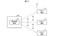
図8に示すように、本実施形態に係るビールディスペンサ4aは、同時に3つのグラスに対してビールを注出したり、異なる種類のビールを注出できるように、ビール注出口Pout、コック46、コックレバー47、ビール冷却管43をそれぞれ3個ずつ備えている。そして、各コックレバー47は、それぞれコックレバー基板1a~1cを備えている。一方、ビールディスペンサ4aの本体部40aは、1つの電力制御基板2aを備えている。
図8に示すように、本実施形態に係るビールディスペンサ4aは、同時に3つのグラスに対してビールを注出したり、異なる種類のビールを注出できるように、ビール注出口Pout、コック46、コックレバー47、ビール冷却管43をそれぞれ3個ずつ備えている。そして、各コックレバー47は、それぞれコックレバー基板1a~1cを備えている。一方、ビールディスペンサ4aの本体部40aは、1つの電力制御基板2aを備えている。
コックレバー基板1a~1c及び電力制御基板2aは、基本的には第一実施形態のコックレバー基板1及び電力制御基板2と同じ構成となっているが、無線通信が一対一の関係ではなく、三対一の関係にある点において、以下に説明する工夫が施されている。
まず、コックレバー基板1a~1cそれぞれと電力制御基板2aとの間の各無線通信(送受信)は、互いの間で電波干渉を発生させない構成となっている。
また、コックレバー基板1a~1cそれぞれには、固有の識別子(ID)が付与されており、この識別子を示すデータが各EEPROM15に記憶されている。そして、各CPU11は、無線ユニット13から送信させる注出開始信号及び注出終了信号に、識別子データを含ませることとしている。
一方、電力制御基板2aのCPU21は、無線ユニット23において受信した注出開始信号及び注出終了信号に含まれる識別子データに基づき、3つのコック46のうちの何れにおいて注出を開始し、また注出を終了したかを判別しつつ電力制御部22に対する制御指示を行う。具体的には、何れかのコック46が注出を開始すると電力制御部22へON指示を行い、全てのコック46での注出が終了し、その後一定時間が経過するのを待って、電力制御部22へOFF指示を行う。
これにより、ビール注出口Pout、コック46、コックレバー47が複数備わっている場合であっても、適切な制御が可能となる。
なお、ビールディスペンサ4aが備えるコックレバーの個数は、3個に限定されるわけではなく、2個であってもよいし、4個以上であってもよい。
(複数のビールディスペンサ間の混信防止)
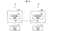
上述した識別子を用いる無線通信は、図9に示すように複数のビールディスペンサ4a・4bを互いに近傍に設置する場合にも有効である。
上述した識別子を用いる無線通信は、図9に示すように複数のビールディスペンサ4a・4bを互いに近傍に設置する場合にも有効である。
識別子を用いない場合には、例えば、ビールディスペンサ4aのコックレバー基板1aから送信された注出開始信号及び注出終了信号を、ビールディスペンサ4bの電力制御基板2bがコックレバー基板1bから送信されたものと誤って認識し、それに基づく誤制御を行うといった不具合が生じる。
しかしながら、識別子を用いる無線通信を行うことにより、ビールディスペンサ4bの電力制御基板2bは、受信した注出開始信号及び注出終了信号がコックレバー基板1aから送信されたものか、コックレバー基板1bから送信されたものかを信号に含まれる識別子データによって識別可能であるから、上記のような誤った認識や、それに基づく誤制御を回避することができるようになる。
〔実施形態3〕
本発明の第三実施形態について、図10に基づいて説明すれば、以下のとおりである。なお、説明の便宜上、第一又は第二実施形態において説明した部材と同等の機能を有する部材については、同じ符号を付記し、その説明を省略する。
本発明の第三実施形態について、図10に基づいて説明すれば、以下のとおりである。なお、説明の便宜上、第一又は第二実施形態において説明した部材と同等の機能を有する部材については、同じ符号を付記し、その説明を省略する。
<ビールディスペンサの利用状況を推測するシステム>
上述のビールディスペンサ制御システム3は、無線ユニット13が出力する出力結果を受け、ビールディスペンサ4・4a・4bの利用状況の推測結果を出力する制御部60をさらに備えてよい。
上述のビールディスペンサ制御システム3は、無線ユニット13が出力する出力結果を受け、ビールディスペンサ4・4a・4bの利用状況の推測結果を出力する制御部60をさらに備えてよい。
図10は、本実施形態に係るビールディスペンサ制御システム3の制御部60の構成を示すブロック図である。
図10に示されるように、制御部60は、集計部61(集計手段)と、特定部62(特定手段)と、推測部63(推測手段)とを備える。
また、制御部60には、記憶部71と、入力部72とが接続されている。
集計部61は、無線ユニット13が出力する出力結果を受け、上述の識別子データによってコックレバー基板を特定する。
ここで、コックレバー基板が特定のコック46と対応するので、集計部61は、識別子データによって上述のコック46が備えるコックレバー47を特定できる。
また、無線ユニット13が出力する信号は、上述の加速度センサ12による検知結果に応じた信号を含む。そして、集計部61は、加速度センサ12による検知履歴を集計する。
特定部62は、無線ユニット13が出力する出力結果を受け、識別子データからビールディスペンサ4・4a・4bの利用者を特定する。当該利用者は、例えば、ビールディスペンサ4・4a・4bの購入者であってよい。
なお、特定部62は、例えば、識別子データとビールディスペンサ4・4a・4bの購入者との対応を示す、記憶部71に記憶された対応表を参照してよい。当該対応表は、ビールディスペンサ4・4a・4bの販売者が入力部72を利用して入力したものであってもよいし、外部ネットワーク80を介して外部からダウンロードされたものであってもよい。
推測部63は、集計部61による集計結果から特定部62が特定した利用者ごとのビールディスペンサ4・4a・4bの利用状況を推測する。なお、推測部63は、当該利用状況(推測結果)を、外部へ出力してもよいし、外部ネットワーク80を介して外部へアップロードしてもよい。
以上の構成により、例えば、ビールディスペンサ4・4a・4bの販売者は、ビールディスペンサ4・4a・4bの購入者によるビールディスペンサ4・4a・4bの利用状況を推測でき、ビール販売計画などを的確に行うことができるようになる。
なお、上述の販売者は、ビールディスペンサ4・4a・4bの貸主であってもよい。また、上述の購入者は、ビールディスペンサ4・4a・4bの借主であってもよい。つまり、販売者が購入者にビールディスペンサ4・4a・4bを販売する形態に限定されず、貸主が借主にビールディスペンサ4・4a・4bを貸与してもよい。この形態においても、貸主は、借主によるビールディスペンサ4・4a・4bの利用状況を推測でき、ビール販売計画などを的確に行うことができるようになる。
〔ソフトウェアによる実現例〕
ビールディスペンサ制御システム3の制御部60は、集積回路(ICチップ)等に形成された論理回路(ハードウェア)によって実現してもよいし、CPU(Central Processing Unit)を用いてソフトウェアによって実現してもよい。
ビールディスペンサ制御システム3の制御部60は、集積回路(ICチップ)等に形成された論理回路(ハードウェア)によって実現してもよいし、CPU(Central Processing Unit)を用いてソフトウェアによって実現してもよい。
後者の場合、ビールディスペンサ制御システム3は、各機能を実現するソフトウェアであるプログラムの命令を実行するCPU、上記プログラムおよび各種データがコンピュータ(又はCPU)で読み取り可能に記録されたROM(Read Only Memory)又は記憶装置(これらを「記録媒体」と称する)、上記プログラムを展開するRAM(Random Access Memory)などを備えている。そして、コンピュータ(又はCPU)が上記プログラムを上記記録媒体から読み取って実行することにより、本発明の目的が達成される。上記記録媒体としては、「一時的でない有形の媒体」、例えば、テープ、ディスク、カード、半導体メモリ、プログラマブルな論理回路などを用いることができる。また、上記プログラムは、該プログラムを伝送可能な任意の伝送媒体(通信ネットワークや放送波等)を介して上記コンピュータに供給されてもよい。なお、本発明は、上記プログラムが電子的な伝送によって具現化された、搬送波に埋め込まれたデータ信号の形態でも実現され得る。
〔まとめ〕
本発明に係るコック操作部材は、当該コック操作部材の動きを検知する検知手段と、上記検知手段による検知結果に応じた信号を外部へ出力する出力手段と、を備える。
本発明に係るコック操作部材は、当該コック操作部材の動きを検知する検知手段と、上記検知手段による検知結果に応じた信号を外部へ出力する出力手段と、を備える。
上記コック操作部材は、液体ディスペンサのコックを操作するためのものであり、ユーザが手で握って操作するタイプのもの、コップ等の容器を押し当てて操作するタイプのものなど種々のタイプのものが考えられ、またその形状も、レバー状のもの、蛇口のハンドルのような形状のものなど種々のものが考えられる。
上記の構成では、コック操作部材に、当該コック操作部材の動きを検知する検知手段と、その検知結果に応じた信号を外部へ出力する出力手段とが備わっている。そのため、既存の液体ディスペンサに設けられているコックレバー等を、上記コック操作部材に取り替えるだけの簡単な改造により、コック操作の的確な検知を実現することができる。
なお、上記コック操作部材のコックへの取付構造は、ねじ込みなどの簡単に脱着できる構造であることが望ましい。
また、本発明に係るコック操作部材では、上記出力手段は、無線通信により上記信号を外部へ出力してもよい。
有線通信による出力手段としては電気配線が考えられるが、これを採用する場合には電気配線の取り回しが必要となるため、改造作業がやや複雑化したり、美観を損なったりするおそれがある。
これに対して、無線通信による出力手段であれば、上記のような問題を回避しやすい。
また、本発明に係るコック操作部材では、上記検知手段は、加速度センサ又はジャイロセンサからなってもよい。
検知手段はコック操作部材に内蔵されていることが望ましいが、上記の構成では、それが容易に実現できる。
また、本発明に係るコック操作部材は、上記検知手段による検知履歴に応じた表示を行う表示手段をさらに備えてもよい。
上記の構成では、検知履歴に応じた表示により液体ディスペンサから注出された液体の量などを推し量ることが可能となる。その結果、注出される液体の残量管理や発注計画などを的確に行うことができるようになる。なお、検知履歴としては、検知回数や検知されている期間の累積時間などが考えられる。
また、本発明に係るコック操作部材は、上記液体ディスペンサを流れる液体と、上記コック操作部材との温度差によって発電する発電装置をさらに備えてもよい。
上記の構成では、液体ディスペンサを流れる液体と、コック操作部材との温度差を利用して発電し、発電した電力をコック操作部材が備える要素に供給できる。以上により、コック操作部材は、電池などの有限の電力源又は外部電源からの電力供給を必要としなくなる。また、コック操作部材は、液体ディスペンサが動作する限り半永久的に動作できるようになる。
また、本発明に係る電力制御装置は、上記コック操作部材における上記出力手段からの信号を入力として受け付ける入力手段と、電力が入力される電力入力部と、電力を外部へ出力する電力出力部と、上記入力手段が受け付けた信号に基づいて、上記電力入力部に入力された電力を制御して上記電力出力部から出力させる電力制御手段と、を備える。
上記の構成では、液体ディスペンサに備えられる撹拌装置などへの電力供給経路に当該電力制御装置を介在させることにより、コック操作部材における検知手段の検知結果に応じて撹拌装置などへの電力供給を制御できるようになる。その結果、液体ディスペンサの消費電力の削減効果の向上を図ることができる。
撹拌装置などへの電力供給経路に当該電力制御装置を介在させるには、次のようにすればよい。電力供給配線の途中には、撹拌装置などの故障時の交換を容易にするために、コネクタを設けて当該電力供給配線を途中で切り離すことができるようになっている場合がある。この場合には、そのコネクタを切り離して、電力供給側のコネクタを上記電力入力部へ接続し、電力消費側のコネクタを上記電力出力部へ接続すればよい。また、電力供給配線の途中にコネクタが設けられていない場合でも、電力供給配線の途中を切断し、その電力供給側を上記電力入力部へ接続し、電力消費側を上記電力出力部へ接続すればよい。何れの場合も、改造作業は容易なものとなる。
また、本発明に係る液体ディスペンサ制御システムは、上記コック操作部材と、上記電力制御装置と、を備えて構成される。
また、本発明に係る液体ディスペンサ制御システムでは、上記出力手段と上記入力手段とは無線通信により上記信号の送受信を行うとともに、上記信号には予め定めた識別子データが含まれてもよい。
上記構成により、ビール注出口、コック、コックレバーが複数備わっている場合であっても、適切な制御が可能となる。
また、本発明に係る液体ディスペンサ制御システムは、上記出力手段が出力する出力結果を受け、上記識別子データによって特定される上記コック操作部材ごとに、上記検知手段による検知履歴を集計する集計手段と、上記出力手段が出力する出力結果を受け、上記識別子データから上記液体ディスペンサの利用者を特定する特定手段と、上記集計手段による集計結果から、上記特定手段が特定した利用者ごとの上記液体ディスペンサの利用状況を推測する推測手段とをさらに備えてよい。
上記構成により、例えば、液体ディスペンサの販売者(又は貸主)は、液体ディスペンサの購入者(又は借主)による液体ディスペンサの利用状況を推測でき、ビール販売計画などを的確に行うことができるようになる。
本発明に係る液体ディスペンサ制御システムは、コンピュータによって実現してもよく、この場合には、コンピュータを上記液体ディスペンサ制御システムが備える各手段として動作させることにより上記液体ディスペンサ制御システムをコンピュータにて実現させる液体ディスペンサ制御システムのプログラム、及びそれを記録したコンピュータ読み取り可能な記録媒体も、本発明の範疇に入る。
また、本発明に係る液体ディスペンサは、上記液体ディスペンサ制御システムと、熱交換媒体を貯蔵する貯蔵槽と、上記貯蔵槽内の熱交換媒体の熱量を制御する熱量制御装置と、上記貯蔵槽内を経て上記コックへと至る中空管と、上記貯蔵槽内の熱交換媒体を撹拌する撹拌装置とを備え、上記撹拌装置は、上記電力出力部から出力される電力により駆動される。
〔付記事項〕
本発明は上述した各実施形態に限定されるものではなく、請求項に示した範囲で種々の変更が可能であり、異なる実施形態にそれぞれ開示された技術的手段を適宜組み合わせて得られる実施形態についても本発明の技術的範囲に含まれる。
本発明は上述した各実施形態に限定されるものではなく、請求項に示した範囲で種々の変更が可能であり、異なる実施形態にそれぞれ開示された技術的手段を適宜組み合わせて得られる実施形態についても本発明の技術的範囲に含まれる。
本発明は、ビールなどの液体を冷却する液体ディスペンサだけでなく、利用者に提供する対象物を加熱や保温する液体ディスペンサにも利用することができる。また、本発明は、液体ディスペンサから注出される液体の残量管理や発注計画などを的確に行うシステムや、当該システムを使用したビジネスモデルにも利用することができる。
1 コックレバー基板
1a コックレバー基板
1b コックレバー基板
1c コックレバー基板
2 電力制御基板(電力制御装置)
2a 電力制御基板(電力制御装置)
2b 電力制御基板(電力制御装置)
3 ビールディスペンサ制御システム(液体ディスペンサ制御システム)
4 ビールディスペンサ(液体ディスペンサ)
4a ビールディスペンサ(液体ディスペンサ)
4b ビールディスペンサ(液体ディスペンサ)
12 加速度センサ(検知手段)
13 無線ユニット(出力手段)
14 液晶ディスプレイ(表示手段)
22 電力制御部(電力制御手段)
23 無線ユニット(入力手段)
27 電力入力部
28 電力出力部
41 水槽(貯蔵槽)
42 冷凍ユニット(熱量制御装置)
43 ビール冷却管(中空管)
44 撹拌装置
47 コックレバー(コック操作部材)
61 集計部(集計手段)
62 特定部(特定手段)
63 推測部(推測手段)
1a コックレバー基板
1b コックレバー基板
1c コックレバー基板
2 電力制御基板(電力制御装置)
2a 電力制御基板(電力制御装置)
2b 電力制御基板(電力制御装置)
3 ビールディスペンサ制御システム(液体ディスペンサ制御システム)
4 ビールディスペンサ(液体ディスペンサ)
4a ビールディスペンサ(液体ディスペンサ)
4b ビールディスペンサ(液体ディスペンサ)
12 加速度センサ(検知手段)
13 無線ユニット(出力手段)
14 液晶ディスプレイ(表示手段)
22 電力制御部(電力制御手段)
23 無線ユニット(入力手段)
27 電力入力部
28 電力出力部
41 水槽(貯蔵槽)
42 冷凍ユニット(熱量制御装置)
43 ビール冷却管(中空管)
44 撹拌装置
47 コックレバー(コック操作部材)
61 集計部(集計手段)
62 特定部(特定手段)
63 推測部(推測手段)
Claims (12)
- 液体ディスペンサのコックを操作するためのコック操作部材において、
当該コック操作部材の動きを検知する検知手段と、
上記検知手段による検知結果に応じた信号を外部へ出力する出力手段と、
を備えることを特徴とするコック操作部材。 - 上記出力手段は、無線通信により上記信号を外部へ出力することを特徴とする請求項1に記載のコック操作部材。
- 上記検知手段は、加速度センサ又はジャイロセンサからなることを特徴とする請求項1又は2に記載のコック操作部材。
- 上記検知手段による検知履歴に応じた表示を行う表示手段をさらに備えることを特徴とする、請求項1から3の何れか1項に記載のコック操作部材。
- 上記液体ディスペンサを流れる液体と、上記コック操作部材との温度差によって発電する発電装置をさらに備えることを特徴とする請求項1から4のいずれか1項に記載のコック操作部材。
- 請求項1から5の何れか1項に記載のコック操作部材における上記出力手段からの信号を入力として受け付ける入力手段と、
電力が入力される電力入力部と、
電力を外部へ出力する電力出力部と、
上記入力手段が受け付けた信号に基づいて、上記電力入力部に入力された電力を制御して上記電力出力部から出力させる電力制御手段と、
を備えることを特徴とする電力制御装置。 - 請求項1から5の何れか1項に記載のコック操作部材と、
請求項6に記載の電力制御装置と、
を備えることを特徴とする液体ディスペンサ制御システム。 - 上記出力手段と上記入力手段とは無線通信により上記信号の送受信を行うとともに、上記信号には予め定めた識別子データが含まれることを特徴とする請求項7に記載の液体ディスペンサ制御システム。
- 上記出力手段が出力する出力結果を受け、上記識別子データによって特定される上記コック操作部材ごとに、上記検知手段による検知履歴を集計する集計手段と、
上記出力手段が出力する出力結果を受け、上記識別子データから上記液体ディスペンサの利用者を特定する特定手段と、
上記集計手段による集計結果から、上記特定手段が特定した利用者ごとの上記液体ディスペンサの利用状況を推測する推測手段と、
をさらに備えることを特徴とする請求項8に記載の液体ディスペンサ制御システム。 - コンピュータを請求項9に記載の各手段として機能させるためのプログラム。
- 請求項10に記載のプログラムを記録したコンピュータ読み取り可能な記録媒体。
- 請求項7から9の何れか1項に記載の液体ディスペンサ制御システムと、
熱交換媒体を貯蔵する貯蔵槽と、
上記貯蔵槽内の熱交換媒体の熱量を制御する熱量制御装置と、
上記貯蔵槽内を経て上記コックへと至る中空管と、
上記貯蔵槽内の熱交換媒体を撹拌する撹拌装置とを備え、
上記撹拌装置は、上記電力出力部から出力される電力により駆動されることを特徴とする液体ディスペンサ。
Priority Applications (1)
| Application Number | Priority Date | Filing Date | Title |
|---|---|---|---|
| CN201480023949.1A CN105283409B (zh) | 2013-06-13 | 2014-06-05 | 液体分配器、与构成液体分配器的旋塞操作部件、电力控制装置、液体分配器控制系统、以及程序和存储介质 |
Applications Claiming Priority (2)
| Application Number | Priority Date | Filing Date | Title |
|---|---|---|---|
| JP2013-125073 | 2013-06-13 | ||
| JP2013125073A JP6195744B2 (ja) | 2013-06-13 | 2013-06-13 | 液体ディスペンサ、及びそれを構成するコック操作部材、電力制御装置、液体ディスペンサ制御システム |
Publications (1)
| Publication Number | Publication Date |
|---|---|
| WO2014199894A1 true WO2014199894A1 (ja) | 2014-12-18 |
Family
ID=52022190
Family Applications (1)
| Application Number | Title | Priority Date | Filing Date |
|---|---|---|---|
| PCT/JP2014/064961 Ceased WO2014199894A1 (ja) | 2013-06-13 | 2014-06-05 | 液体ディスペンサ、及びそれを構成するコック操作部材、電力制御装置、液体ディスペンサ制御システム、並びにプログラム及び記録媒体 |
Country Status (3)
| Country | Link |
|---|---|
| JP (1) | JP6195744B2 (ja) |
| CN (1) | CN105283409B (ja) |
| WO (1) | WO2014199894A1 (ja) |
Cited By (5)
| Publication number | Priority date | Publication date | Assignee | Title |
|---|---|---|---|---|
| EP3059204A3 (en) * | 2015-02-18 | 2016-09-14 | F-LAB S.r.l. | Improved tapping valve and respective electronic control and communication module |
| AT516689A3 (de) * | 2014-12-23 | 2017-07-15 | Ing Günther Gruber Dipl | Griff für einen Zapfhahn, Zapfhahn mit einem derartigen Griff, Zapfanlage und Verfahren zum Zapfen eines Mediums |
| US20230050801A1 (en) * | 2019-12-20 | 2023-02-16 | Essilor International | Method for determining an optical lens |
| US11667510B2 (en) | 2020-06-29 | 2023-06-06 | Amish Patel | Beer tap monitoring system |
| WO2023148589A1 (en) * | 2022-02-01 | 2023-08-10 | Bevco S.R.L. | Environmentally-friendly system for the dispensing of refrigerated beverages |
Families Citing this family (2)
| Publication number | Priority date | Publication date | Assignee | Title |
|---|---|---|---|---|
| KR101778591B1 (ko) | 2015-12-08 | 2017-09-14 | 롯데알미늄 주식회사 | 맥주 디스펜서 및 그의 제어방법 |
| KR102763000B1 (ko) * | 2016-12-12 | 2025-02-07 | 엘지전자 주식회사 | 정수기의 제어 방법 |
Citations (7)
| Publication number | Priority date | Publication date | Assignee | Title |
|---|---|---|---|---|
| JP2002068383A (ja) * | 2000-08-29 | 2002-03-08 | Hoshizaki Electric Co Ltd | 飲料ディスペンサ |
| JP2002096898A (ja) * | 2000-02-01 | 2002-04-02 | Hoshizaki Electric Co Ltd | 飲料ディスペンサ |
| JP2003103050A (ja) * | 2001-09-28 | 2003-04-08 | Nec Tokin Corp | 姿勢角度検出装置及び該装置の操作装置への取り付け方法 |
| JP2006315711A (ja) * | 2005-05-12 | 2006-11-24 | Fuji Electric Retail Systems Co Ltd | 飲料ディスペンサの制御装置 |
| JP2009161204A (ja) * | 2007-12-28 | 2009-07-23 | Hoshizaki Electric Co Ltd | 飲料ディスペンサ |
| JP2010053601A (ja) * | 2008-08-28 | 2010-03-11 | Caterpillar Japan Ltd | 建設機械の操作レバー装置 |
| JP2010108009A (ja) * | 2008-10-28 | 2010-05-13 | Suzuki Motor Corp | 力覚提示装置及び自動二輪シフトシミュレーター |
-
2013
- 2013-06-13 JP JP2013125073A patent/JP6195744B2/ja active Active
-
2014
- 2014-06-05 WO PCT/JP2014/064961 patent/WO2014199894A1/ja not_active Ceased
- 2014-06-05 CN CN201480023949.1A patent/CN105283409B/zh active Active
Patent Citations (7)
| Publication number | Priority date | Publication date | Assignee | Title |
|---|---|---|---|---|
| JP2002096898A (ja) * | 2000-02-01 | 2002-04-02 | Hoshizaki Electric Co Ltd | 飲料ディスペンサ |
| JP2002068383A (ja) * | 2000-08-29 | 2002-03-08 | Hoshizaki Electric Co Ltd | 飲料ディスペンサ |
| JP2003103050A (ja) * | 2001-09-28 | 2003-04-08 | Nec Tokin Corp | 姿勢角度検出装置及び該装置の操作装置への取り付け方法 |
| JP2006315711A (ja) * | 2005-05-12 | 2006-11-24 | Fuji Electric Retail Systems Co Ltd | 飲料ディスペンサの制御装置 |
| JP2009161204A (ja) * | 2007-12-28 | 2009-07-23 | Hoshizaki Electric Co Ltd | 飲料ディスペンサ |
| JP2010053601A (ja) * | 2008-08-28 | 2010-03-11 | Caterpillar Japan Ltd | 建設機械の操作レバー装置 |
| JP2010108009A (ja) * | 2008-10-28 | 2010-05-13 | Suzuki Motor Corp | 力覚提示装置及び自動二輪シフトシミュレーター |
Cited By (5)
| Publication number | Priority date | Publication date | Assignee | Title |
|---|---|---|---|---|
| AT516689A3 (de) * | 2014-12-23 | 2017-07-15 | Ing Günther Gruber Dipl | Griff für einen Zapfhahn, Zapfhahn mit einem derartigen Griff, Zapfanlage und Verfahren zum Zapfen eines Mediums |
| EP3059204A3 (en) * | 2015-02-18 | 2016-09-14 | F-LAB S.r.l. | Improved tapping valve and respective electronic control and communication module |
| US20230050801A1 (en) * | 2019-12-20 | 2023-02-16 | Essilor International | Method for determining an optical lens |
| US11667510B2 (en) | 2020-06-29 | 2023-06-06 | Amish Patel | Beer tap monitoring system |
| WO2023148589A1 (en) * | 2022-02-01 | 2023-08-10 | Bevco S.R.L. | Environmentally-friendly system for the dispensing of refrigerated beverages |
Also Published As
| Publication number | Publication date |
|---|---|
| JP2015000735A (ja) | 2015-01-05 |
| JP6195744B2 (ja) | 2017-09-13 |
| CN105283409B (zh) | 2018-05-11 |
| CN105283409A (zh) | 2016-01-27 |
Similar Documents
| Publication | Publication Date | Title |
|---|---|---|
| JP6195744B2 (ja) | 液体ディスペンサ、及びそれを構成するコック操作部材、電力制御装置、液体ディスペンサ制御システム | |
| US11845643B2 (en) | Beverage dispensing | |
| EP2578119B2 (en) | Beverage production machine and method | |
| US7543453B2 (en) | Measured fill water dispenser for refrigerator | |
| US20140263413A1 (en) | Dispensing System | |
| MX2014000735A (es) | Maquina de produccion de bebida y metodo. | |
| US9010580B2 (en) | Stream detection and/or characterization for beverage dispensing in a refrigerator | |
| CN101663548B (zh) | 冰箱的制冰系统和方法 | |
| KR20010113397A (ko) | 냉장고의 소모품 교환시점 통지장치 및 방법 | |
| US12234139B2 (en) | Fluid dispensing systems and methods | |
| JP6039937B2 (ja) | 飲料ディスペンサーの残量検出装置 | |
| JP5675267B2 (ja) | ディスペンサーの運転方法 | |
| JP2011126569A (ja) | 飲料ディスペンサ | |
| US20240351850A1 (en) | System and method for contactless drink dispensing | |
| JP2012189276A (ja) | 冷蔵庫 | |
| US12391533B2 (en) | Intelligent concentrate mixing and delivery | |
| US20260022004A1 (en) | Ice maker and error display method of it | |
| US20250024987A1 (en) | Automatic water filling for connected small appliance | |
| US20250326623A1 (en) | Cooling and heating water dispenser with multiple water inlets | |
| WO2024054579A1 (en) | Intelligent concentrate mixing and delivery | |
| JP2001067545A (ja) | 飲料自動販売機 | |
| HK1183423A (en) | Beverage production machine and method | |
| JP2009195641A (ja) | 給茶機 | |
| JP2016059060A (ja) | リモートコントローラ | |
| JP2013187694A (ja) | リモートコントローラ |
Legal Events
| Date | Code | Title | Description |
|---|---|---|---|
| WWE | Wipo information: entry into national phase |
Ref document number: 201480023949.1 Country of ref document: CN |
|
| 121 | Ep: the epo has been informed by wipo that ep was designated in this application |
Ref document number: 14811408 Country of ref document: EP Kind code of ref document: A1 |
|
| NENP | Non-entry into the national phase |
Ref country code: DE |
|
| 122 | Ep: pct application non-entry in european phase |
Ref document number: 14811408 Country of ref document: EP Kind code of ref document: A1 |