WO2014199631A1 - 超音波診断装置 - Google Patents
超音波診断装置 Download PDFInfo
- Publication number
- WO2014199631A1 WO2014199631A1 PCT/JP2014/003100 JP2014003100W WO2014199631A1 WO 2014199631 A1 WO2014199631 A1 WO 2014199631A1 JP 2014003100 W JP2014003100 W JP 2014003100W WO 2014199631 A1 WO2014199631 A1 WO 2014199631A1
- Authority
- WO
- WIPO (PCT)
- Prior art keywords
- image
- ultrasonic
- reference image
- cross
- unit
- Prior art date
- Legal status (The legal status is an assumption and is not a legal conclusion. Google has not performed a legal analysis and makes no representation as to the accuracy of the status listed.)
- Ceased
Links
Images


Classifications
-
- A—HUMAN NECESSITIES
- A61—MEDICAL OR VETERINARY SCIENCE; HYGIENE
- A61B—DIAGNOSIS; SURGERY; IDENTIFICATION
- A61B8/00—Diagnosis using ultrasonic, sonic or infrasonic waves
- A61B8/52—Devices using data or image processing specially adapted for diagnosis using ultrasonic, sonic or infrasonic waves
- A61B8/5215—Devices using data or image processing specially adapted for diagnosis using ultrasonic, sonic or infrasonic waves involving processing of medical diagnostic data
-
- A—HUMAN NECESSITIES
- A61—MEDICAL OR VETERINARY SCIENCE; HYGIENE
- A61B—DIAGNOSIS; SURGERY; IDENTIFICATION
- A61B6/00—Apparatus or devices for radiation diagnosis; Apparatus or devices for radiation diagnosis combined with radiation therapy equipment
- A61B6/52—Devices using data or image processing specially adapted for radiation diagnosis
- A61B6/5211—Devices using data or image processing specially adapted for radiation diagnosis involving processing of medical diagnostic data
- A61B6/5229—Devices using data or image processing specially adapted for radiation diagnosis involving processing of medical diagnostic data combining image data of a patient, e.g. combining a functional image with an anatomical image
- A61B6/5247—Devices using data or image processing specially adapted for radiation diagnosis involving processing of medical diagnostic data combining image data of a patient, e.g. combining a functional image with an anatomical image combining images from an ionising-radiation diagnostic technique and a non-ionising radiation diagnostic technique, e.g. X-ray and ultrasound
-
- A—HUMAN NECESSITIES
- A61—MEDICAL OR VETERINARY SCIENCE; HYGIENE
- A61B—DIAGNOSIS; SURGERY; IDENTIFICATION
- A61B8/00—Diagnosis using ultrasonic, sonic or infrasonic waves
- A61B8/42—Details of probe positioning or probe attachment to the patient
- A61B8/4245—Details of probe positioning or probe attachment to the patient involving determining the position of the probe, e.g. with respect to an external reference frame or to the patient
- A61B8/4254—Details of probe positioning or probe attachment to the patient involving determining the position of the probe, e.g. with respect to an external reference frame or to the patient using sensors mounted on the probe
-
- A—HUMAN NECESSITIES
- A61—MEDICAL OR VETERINARY SCIENCE; HYGIENE
- A61B—DIAGNOSIS; SURGERY; IDENTIFICATION
- A61B8/00—Diagnosis using ultrasonic, sonic or infrasonic waves
- A61B8/52—Devices using data or image processing specially adapted for diagnosis using ultrasonic, sonic or infrasonic waves
- A61B8/5215—Devices using data or image processing specially adapted for diagnosis using ultrasonic, sonic or infrasonic waves involving processing of medical diagnostic data
- A61B8/5238—Devices using data or image processing specially adapted for diagnosis using ultrasonic, sonic or infrasonic waves involving processing of medical diagnostic data for combining image data of patient, e.g. merging several images from different acquisition modes into one image
- A61B8/5261—Devices using data or image processing specially adapted for diagnosis using ultrasonic, sonic or infrasonic waves involving processing of medical diagnostic data for combining image data of patient, e.g. merging several images from different acquisition modes into one image combining images from different diagnostic modalities, e.g. ultrasound and X-ray
-
- G—PHYSICS
- G16—INFORMATION AND COMMUNICATION TECHNOLOGY [ICT] SPECIALLY ADAPTED FOR SPECIFIC APPLICATION FIELDS
- G16H—HEALTHCARE INFORMATICS, i.e. INFORMATION AND COMMUNICATION TECHNOLOGY [ICT] SPECIALLY ADAPTED FOR THE HANDLING OR PROCESSING OF MEDICAL OR HEALTHCARE DATA
- G16H50/00—ICT specially adapted for medical diagnosis, medical simulation or medical data mining; ICT specially adapted for detecting, monitoring or modelling epidemics or pandemics
- G16H50/20—ICT specially adapted for medical diagnosis, medical simulation or medical data mining; ICT specially adapted for detecting, monitoring or modelling epidemics or pandemics for computer-aided diagnosis, e.g. based on medical expert systems
-
- A—HUMAN NECESSITIES
- A61—MEDICAL OR VETERINARY SCIENCE; HYGIENE
- A61B—DIAGNOSIS; SURGERY; IDENTIFICATION
- A61B6/00—Apparatus or devices for radiation diagnosis; Apparatus or devices for radiation diagnosis combined with radiation therapy equipment
- A61B6/50—Apparatus or devices for radiation diagnosis; Apparatus or devices for radiation diagnosis combined with radiation therapy equipment specially adapted for specific body parts; specially adapted for specific clinical applications
- A61B6/503—Apparatus or devices for radiation diagnosis; Apparatus or devices for radiation diagnosis combined with radiation therapy equipment specially adapted for specific body parts; specially adapted for specific clinical applications for diagnosis of the heart
-
- A—HUMAN NECESSITIES
- A61—MEDICAL OR VETERINARY SCIENCE; HYGIENE
- A61B—DIAGNOSIS; SURGERY; IDENTIFICATION
- A61B8/00—Diagnosis using ultrasonic, sonic or infrasonic waves
- A61B8/08—Clinical applications
- A61B8/0808—Clinical applications for diagnosis of the brain
-
- A—HUMAN NECESSITIES
- A61—MEDICAL OR VETERINARY SCIENCE; HYGIENE
- A61B—DIAGNOSIS; SURGERY; IDENTIFICATION
- A61B8/00—Diagnosis using ultrasonic, sonic or infrasonic waves
- A61B8/08—Clinical applications
- A61B8/0883—Clinical applications for diagnosis of the heart
-
- A—HUMAN NECESSITIES
- A61—MEDICAL OR VETERINARY SCIENCE; HYGIENE
- A61B—DIAGNOSIS; SURGERY; IDENTIFICATION
- A61B8/00—Diagnosis using ultrasonic, sonic or infrasonic waves
- A61B8/44—Constructional features of the ultrasonic, sonic or infrasonic diagnostic device
- A61B8/4444—Constructional features of the ultrasonic, sonic or infrasonic diagnostic device related to the probe
-
- A—HUMAN NECESSITIES
- A61—MEDICAL OR VETERINARY SCIENCE; HYGIENE
- A61B—DIAGNOSIS; SURGERY; IDENTIFICATION
- A61B8/00—Diagnosis using ultrasonic, sonic or infrasonic waves
- A61B8/46—Ultrasonic, sonic or infrasonic diagnostic devices with special arrangements for interfacing with the operator or the patient
- A61B8/461—Displaying means of special interest
- A61B8/463—Displaying means of special interest characterised by displaying multiple images or images and diagnostic data on one display
-
- A—HUMAN NECESSITIES
- A61—MEDICAL OR VETERINARY SCIENCE; HYGIENE
- A61B—DIAGNOSIS; SURGERY; IDENTIFICATION
- A61B8/00—Diagnosis using ultrasonic, sonic or infrasonic waves
- A61B8/46—Ultrasonic, sonic or infrasonic diagnostic devices with special arrangements for interfacing with the operator or the patient
- A61B8/461—Displaying means of special interest
- A61B8/466—Displaying means of special interest adapted to display 3D data
Definitions
- Embodiments described herein relate generally to an ultrasonic diagnostic apparatus, and to an ultrasonic diagnostic apparatus that displays an image acquired by a medical image diagnostic apparatus together with an ultrasonic image as a reference image.
- an ultrasonic diagnostic apparatus is used as a medical apparatus.
- the ultrasonic diagnostic apparatus can be connected to various modalities such as an X-ray CT apparatus (X-ray computed tomography apparatus) and an MRI apparatus (magnetic resonance imaging apparatus) via a hospital network. Diagnosis and treatment of diseases are supported using images acquired by other medical image diagnostic apparatuses.
- a CT image of the same cross section as an ultrasonic image is obtained by aligning a cross section scanned by an ultrasonic probe with a CT image or MRI image in which a lesion is detected using a magnetic position sensor.
- an ultrasonic diagnostic apparatus that displays an MRI image as a reference image and navigates an ultrasonic probe to the position of a lesion is known.
- the function of aligning and displaying the ultrasonic image (echo image) and the reference image (hereinafter referred to as the “Fusion function”) is an indispensable function for medical treatment of initial cancer.
- the magnetic position sensor is provided in a magnetic field formed by a transmitter, for example, and is attached to the ultrasonic probe.
- the problem to be solved by the invention is to provide an ultrasonic diagnostic apparatus that sets the orientation of the cross section of the initial display of the reference image in accordance with the diagnostic purpose and the type of probe.
- An ultrasonic diagnostic apparatus is attached to an ultrasonic image generation unit that generates an ultrasonic image based on a reception signal from an ultrasonic probe that transmits / receives ultrasonic waves to / from a subject, and the ultrasonic probe
- a position information acquisition unit that acquires position information of the ultrasonic probe in a three-dimensional space
- an image acquisition unit that acquires image data and obtains a reference image corresponding to the ultrasonic image
- a reference image forming unit that specifies a cross-sectional direction in which the reference image is to be displayed in accordance with at least one of information on the diagnostic purpose of the specimen and information on the type of ultrasonic probe, and forms a reference image in the specified cross-sectional direction
- a display unit for displaying a reference image formed by the reference image forming unit and an ultrasonic image from the ultrasonic image generating unit.
- FIG. 1 is a block diagram showing a schematic configuration of an ultrasonic diagnostic apparatus according to an embodiment.
- Explanatory drawing which shows arrangement
- Explanatory drawing which shows the example of a display of the reference image and ultrasonic image in embodiment.
- the block diagram which shows the structure of CPU and its periphery part in embodiment.
- Explanatory drawing which shows schematically the direction of the cross section in embodiment.
- Explanatory drawing which shows the mode at the time of the diagnosis of the prostate in embodiment.
- Explanatory drawing which shows the rotation process of the reference image in embodiment.
- Explanatory drawing which shows the scanning example of the abdomen and the heart by the probe in embodiment.
- Explanatory drawing which shows roughly the apex four-chamber cross section in embodiment.
- FIG. 1 is a block diagram illustrating a schematic configuration of an ultrasonic diagnostic apparatus 10 according to an embodiment.
- a main body 100 of an ultrasonic diagnostic apparatus includes an ultrasonic probe 11 that transmits / receives ultrasonic waves to / from a subject (not shown), and an ultrasonic probe 11 that drives the ultrasonic probe 11 to A transmission / reception unit 12 that performs acoustic wave scanning, and a data processing unit 13 that processes reception signals obtained by the transmission / reception unit 2 to generate image data such as B-mode image data and Doppler image data.
- the main body 100 collects and stores the image generation unit 14 that generates two-dimensional image data based on the image data output from the data processing unit 13 and the image data generated by the image generation unit 14.
- An image database 15 is provided.
- the main body 100 further includes a central processing unit (CPU) 16 that controls the entire apparatus, a storage unit 17, and an interface unit 18 for connecting the main body 100 to the network 22.
- An operation unit 19 for inputting various command signals and a position information acquisition unit 20 are connected to the interface 18 unit.
- the main body 100 is connected to a monitor (display unit) 21 that displays an image generated by the image generation unit 14.
- the CPU 16 and each circuit unit are connected via a bus line 101.
- the interface 18 can be connected to the network 22, and the image data acquired by the ultrasonic diagnostic apparatus 10 can be stored in the external medical server 23 via the network 22.
- the network 22 is connected to a medical image diagnostic apparatus 24 such as an MRI apparatus, an X-ray CT apparatus, or a nuclear medicine diagnostic apparatus.
- the medical image data acquired by the medical image diagnostic apparatus 24 is stored in the medical server 23. be able to.
- the ultrasonic probe 11 performs ultrasonic wave transmission / reception by bringing its tip surface into contact with the body surface of the subject, and has, for example, a plurality of piezoelectric vibrators arranged one-dimensionally.
- the piezoelectric vibrator is an electroacoustic transducer, which converts an ultrasonic drive signal into a transmission ultrasonic wave during transmission, and converts a reception ultrasonic wave from the subject into an ultrasonic reception signal during reception.
- the ultrasonic probe 11 is a sector type, a linear type, a convex type or the like. In the following description, the ultrasonic probe 11 may be simply referred to as a probe.
- the scissor transmission / reception unit 12 includes a transmission unit 121 that generates an ultrasonic drive signal and a reception unit 122 that processes an ultrasonic reception signal obtained from the ultrasonic probe 1.
- the transmission unit 121 generates an ultrasonic drive signal and outputs it to the probe 11, and the reception unit 122 outputs an ultrasonic reception signal (echo signal) from the piezoelectric vibrator to the data processing unit 13.
- the eyelid data processing unit 13 includes a B-mode processing unit 131 that generates B-mode image data from a signal output from the transmission / reception unit 12, a Doppler processing unit 132 that generates Doppler image data, and the like.
- the B mode processing unit 131 performs envelope detection on the signal from the transmission / reception unit 12 and then performs logarithmic conversion, converts the logarithmically converted signal into a digital signal, generates B mode image data, and generates the image generation unit 14. Output to.
- the Doppler processing unit 132 detects the Doppler shift frequency for the signal from the transmission / reception unit 12 and converts it to a digital signal, extracts blood flow and tissue due to the Doppler effect, generates Doppler data, and generates the image generation unit 14. Output to.
- the image generation unit 14 generates an ultrasonic image using the B-mode image data, Doppler image data, etc. output from the data processing unit 13.
- the image generation unit 14 includes a DSC (Digital Scan Converter), performs scan conversion of the generated image data, and generates an ultrasonic image (B-mode image or Doppler image) that can be displayed on the monitor 21. Therefore, the ultrasonic probe 11, the transmission / reception unit 12, the data processing unit 13, and the image generation unit 14 constitute an ultrasonic image generation unit that generates an ultrasonic image.
- DSC Digital Scan Converter
- the image database 15 stores the image data generated by the image generation unit 14.
- the image database 15 includes three-dimensional image data taken by another medical image diagnostic apparatus 24 (such as an MRI apparatus or an X-ray CT apparatus) via the interface unit 18, for example, data such as an MPR (Multi-Planer Reconstruction) image. Is acquired and memorized.
- the acquired three-dimensional image data can be used to obtain a reference image (described later) corresponding to the ultrasonic image. Therefore, the image database 15 and the interface unit 18 constitute an image acquisition unit that acquires three-dimensional image data.
- the CPU 16 controls the entire ultrasound diagnostic apparatus 10 and executes various processes. For example, the transmission / reception unit 12, the data processing unit 13, and the image generation unit 14 are controlled based on various setting requests input from the operation unit 19 and various control programs and various setting information read from the storage unit 17. Further, control is performed so that the ultrasonic image stored in the image database 15 is displayed on the monitor 21.
- the storage unit 17 stores various data such as a control program for performing ultrasonic transmission / reception, image processing and display processing, diagnostic information (for example, subject ID, doctor's findings, etc.), diagnostic protocol, and the like. Furthermore, the storage unit 17 is also used for storing images stored in the image database 15 as necessary. The storage unit 17 stores various information used for processing by the CPU 16.
- the interface unit 18 is an interface that controls the exchange of various information between the operation unit 19, the position information acquisition unit 20 and the network 22, and the main body 100.
- the operation unit 19 includes input devices such as various switches, a keyboard, a trackball, a mouse, and a touch command screen, receives various setting requests from an operator, and transfers various setting requests to the main body 100. For example, the operation unit 19 receives various operations related to the alignment between the ultrasonic image and the X-ray CT image.
- the monitor 21 displays a GUI (Graphical User Interface) for the operator of the ultrasonic diagnostic apparatus 10 to input various setting requests by operating the operation unit 19, or an ultrasonic image generated in the main body 100, Line CT images and the like are displayed in parallel.
- GUI Graphic User Interface
- the CPU 16 for example, conforms to the DICOM (Digital Imaging and Communications in Medicine) standard and transmits the three-dimensional image data of another medical image diagnostic apparatus 24 (for example, an X-ray CT apparatus, an MRI apparatus, etc.) to the network 22. Send and receive via.
- DICOM Digital Imaging and Communications in Medicine
- three-dimensional image data such as an X-ray CT apparatus and an MRI apparatus can be stored in a storage medium such as a CD, DVD, or USB, and the data stored in the storage medium can be taken into the ultrasonic diagnostic apparatus 10. .
- the eyelid position information acquisition unit 20 acquires position information indicating where the ultrasonic probe 11 is located, for example.
- the position information acquisition device 20 for example, a magnetic sensor, an infrared sensor, an optical sensor, a camera, or the like is used. In the following description, an example using a magnetic sensor will be described.
- the position information acquisition unit 20 when the subject is scanned by the ultrasonic probe 11, a CT image or MRI image in which a lesion is detected is displayed as a reference image, and the position of the cross section to be scanned and the position of the reference image is the same. In order to match, a position information acquisition unit 20 is provided.
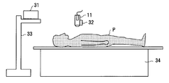
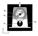
- FIG. 2 is an explanatory diagram schematically showing the arrangement of position sensors in the position information acquisition unit 20. That is, the position sensor system of FIG. 2 includes a transmitter 31 (transmitter) and a position sensor (receiver) 32.
- the transmitter 31 is, for example, a magnetic transmitter, is attached to a pole 33 or the like at a fixed position near the bed 34, and transmits a reference signal.
- the transmitter 31 forms a magnetic field toward the outside centering on its own device.
- the transmitter 31 may be attached to the tip of an arm attached to the ultrasonic diagnostic apparatus main body, or may be attached to the tip of an arm of a movable pole stand.
- a position sensor 32 made of, for example, a magnetic sensor is attached to a three-dimensional magnetic field formed by the transmitter 31 in an area where the magnetism transmitted from the transmitter 31 can be received.
- the position sensor 32 may be simply referred to as the sensor 32.
- the sensor 32 is attached to the ultrasonic probe 11 and receives the reference signal from the transmitter 31 to acquire position information in the three-dimensional space and detect the position and posture (tilt) of the ultrasonic probe 11.
- the position information of the sensor 32 is supplied to the CPU 16 via the interface unit 18.
- the CPU 16 aligns an arbitrary cross section of the three-dimensional image data generated by the medical image diagnostic apparatus 24 with a cross section scanned by the ultrasonic probe 11. Then, the 3D image data is associated with the 3D space.
- the CPU 16 acquires the currently displayed ultrasonic image (two-dimensional image) at which position and angle of the subject P based on the detection result of the sensor 32. Calculate what you did.
- the transmitter 31 serves as a reference for the position / angle information (the origin of the coordinate system).
- the volume data of the CT image or MRI image is read into the ultrasonic diagnostic apparatus 10 and the MPR image is displayed.
- the reference image (MPR image) and the ultrasonic image are displayed on the same screen, and the angle adjustment for matching the scanning direction of the ultrasonic probe 11 to the direction corresponding to the orientation (Orientation) of the cross section of the reference image, and the reference image A point is set on a mark observable in both the ultrasonic image and the ultrasonic image, and alignment is performed by mark alignment that matches the position. That is, by associating the direction and coordinates of the position sensor 32 with the coordinates of the volume data, a two-dimensional image at the same position as the current scanning plane of the ultrasonic probe 11 can be generated from the volume data of other modalities. It is possible to display an ultrasonic image that changes with the movement of the ultrasonic probe and an MPR image of the same cross section.
- the same cross section as the ultrasonic image that changes with the movement of the probe 11 can be displayed as an MPR image. Therefore, a tumor or the like that is difficult to confirm with an ultrasonic image can be confirmed with an MPR image.
- the function of aligning and combining the ultrasonic image (echo image) and the reference image for display is referred to as a “Fusion” function in the following description.
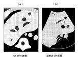
- FIG. 3 shows a reference image (a) and an ultrasonic image (b) after alignment.
- the reference image (a) for example, an MPR image (Multi-Planer Reconstruction image) generated from volume data collected by an X-ray CT apparatus is used.
- an image acquired by an MRI apparatus can be used.
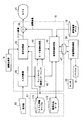
- FIG. 4 is a block diagram showing the configuration of the CPU 16 and its peripheral part, which are characteristic parts of the present embodiment.
- the CPU 16 includes an input determination unit 41, a controller 42 including control software, a display processing unit 43, a mode conversion processing unit 44, a reference image forming unit 45, and a combining unit 46.
- the storage unit 17 includes a system information table 171 in which information on the type of the selected probe and information for diagnostic purposes are stored, and a database 172 in which cross-sectional direction data is stored.
- the image database 15 is for medical use other than the ultrasonic diagnostic apparatus 10. A three-dimensional image such as a CT image or an MRI image acquired from the diagnostic imaging apparatus 24 is stored.
- the system information table 171 is connected to the display processing unit 43, and the database 172 is connected to the reference image forming unit 45.
- the image database 15 is connected to the reference image forming unit 45.
- the input determination unit 41 is connected to the operation unit 19, determines what input operation is performed on the operation unit 19, and supplies the determination information to the controller 32.
- the controller 42 is connected to the mode conversion processing unit 44 and the reference image forming unit 45, and the mode conversion processing unit 44 is connected to the display processing unit 43 and the reference image forming unit 45.
- the reference image forming unit 45 is connected to the position information acquisition unit 20 via the cable 47, and the reference image formed by the reference image forming unit 45 and the echo image processed by the display processing unit 43 are combined by the combining unit 46. And output to the monitor 21.
- the application of the Fusion function is based on the premise that the ultrasonic probe 11 is applied to the body surface, and the diagnostic purpose (Exam ⁇ Type) is mainly the abdomen. .
- the first method is a method in which the probe is applied from the body surface of the subject as in the conventional diagnosis of the abdomen, and is mainly used for observing the state of prostatic hypertrophy.
- the probe to be used is a convex probe for body surface (for example, PVT-375BT manufactured by Toshiba).
- the second method is a method of observing the prostate through a wall of the rectum by inserting a probe from the anus, and is mainly used for observing prostate cancer. This second method may also be used for observation of prostate enlargement.
- the probe used is a convex probe in a body cavity (for example, PVT-781VT manufactured by Toshiba).
- MRI images or CT images are often used as the reference image for the Fusion function, and the orientation of the cross-section (Orientation) of the reference image is often used axially. That is, in the Fusion function, in the initial alignment with the MRI image, it is necessary to match both the angle and the position, but at this time, the operation is often performed on the basis of the axial section. This is because the operator can easily understand.
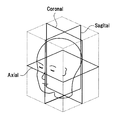
- FIG. 5 is an explanatory view schematically showing the direction of a cross section in the CT apparatus and the MRI apparatus.
- the reference cross section directions such as a body axis cross section (Axial) horizontal to the subject, a vertical cross section (Sagittal), and a cross section (Coronal) are generally known. ing.
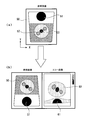
- FIG. 6 is an explanatory diagram showing a state of prostate diagnosis.
- a phantom is used instead of the subject, and an axial cross section of the CT image 50 is shown.
- 51 is a rectal hole
- 52 is the urethra
- 53 is a tumor.
- ultrasonic imaging is performed by applying a probe from the body surface (in the direction of arrow A) as indicated by a thick solid line.
- ultrasonic imaging is performed by applying a probe from within a body cavity (state inserted from the rectum: direction of arrow B).
- the orientation of the cross section of the reference image composed of the CT image 51 is axial, but the positional relationship of the obtained echo images when the ultrasonic probe 11 is applied from the body surface and when applied from the body cavity. Is different. Therefore, when observing from the rectal wall using the probe in the body cavity, the axial section of the reference image and the direction of the echo image may be reversed.
- FIG. 7 is an explanatory diagram showing a general rotation process of a reference image.
- FIG. 7A shows a reference image 50 (CT image) read into the image database.
- CT image reference image
- FIG. 7B a reference image 50 and an echo image 60 taken by the ultrasonic apparatus are displayed side by side.
- 61 is a rectal hole
- 62 is a urethra
- 63 is a tumor.
- the reference image 50 is rotated 180 degrees with respect to the X axis as shown in FIG. 7C.
- the operation direction of the probe is restricted due to the structure of the human body, and therefore the insertion angle is inclined to some extent with respect to the axial axis (for example, it tends to be inclined about 30 degrees). is there). Therefore, when the reference image is rotated in prostate diagnosis, an image suitable for diagnosis is rotated by 150 degrees (180-30 degrees).
- the direction of the cross section of the reference image is initialized in advance according to the diagnosis purpose (for example, diagnosis of the prostate, heart, viscera, etc.) and the reference image needs to be rotated, ultrasonic waves
- the rotation angle is initially set in accordance with the type of probe 11 (body surface probe, body cavity probe).
- the orientation and the rotation angle of the cross section of the reference image are automatically set by the initial setting.
- An adjusted reference image can be generated and displayed with the echo image.
- FIG. 8 is an explanatory diagram illustrating a reference image rotation process according to the embodiment.
- FIG. 8A shows a reference image 50 (CT image) read into the image database 15.
- CT image reference image
- FIG. 8B the reference image 50 and the echo image 60 photographed by the ultrasonic apparatus are displayed side by side.
- the reference image 50 displays an image of an axial section according to the initial setting, and displays an image obtained by rotating the reference image 50 by 150 degrees with respect to the X axis. Therefore, the operator can reduce time and labor without adjusting the reference image many times.
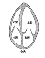
- the probe when diagnosing multiple parts with the same probe, it is better to change the direction of the cross section of the reference image depending on the purpose of diagnosis. For example, as shown in FIG. 9, when the sector probe is used, the probe is generally placed in the direction corresponding to the axial section in the abdominal scan, but in the cardiac scan, the apical four-chamber section is not axial but the axial section. It is easier to diagnose with the reference plane.
- the apex four-chamber cross section is a cross section suitable for observing the presence or absence of abnormalities in the right atrium right ventricle and the left atrium left ventricle. Often the probe is scanned as is done. Therefore, by initializing the direction of the cross section of the reference image so as to correspond to the four-chamber section of the apex, a reference image suitable for diagnosis can be displayed when the Fusion function is activated.
- a sputum system information table 171 shown in FIG. 4 and a database 172 storing cross-sectional direction data are added to the configuration of the ultrasonic diagnostic imaging apparatus 10, and an initial cross-section of the reference image is added to the reference image forming unit 45. And a process of changing the section direction data of the initial section of the reference image according to the button operation of the operator.
- the controller 42 sets and sets the cross-sectional direction of the reference image according to the diagnostic purpose and the type of ultrasonic probe to be used.
- the cross-sectional direction data is stored in the database 172. That is, the controller 42 constitutes a cross-sectional direction setting unit.
- the cross section of the reference image is axial, and the correction of the rotation angle of the cross section is zero.
- the cross section of the reference image is axial, and the correction of the rotation angle of the cross section is set to 150 degrees as the vertical rotation.
- 150 degrees is a total angle obtained by subtracting (returning) 30 degrees, which is an angle at which the probe 11 is inclined with respect to the axial plane, to a rotation angle of 180 degrees. Since the rotation in the vertical direction rotates around the X axis (horizontal axis) in the graphics coordinate system, it may be called an X-axis rotation amount of 150 degrees.
- the user In such a state, after the user selects a reference image to be used in the Fusion function, the user operates the operation unit 19 and presses the Fusion button for starting the Fusion function.
- the input determination unit 41 detects that the button has been pressed.
- the input determination unit 41 confirms the operation status of all buttons of the operation unit 19 at regular intervals. Therefore, the state change caused by pressing the Fusion button can be determined by the input determination unit 41, and the fact that the Fusion button has been pressed is passed to the controller.
- the controller 42 In response to the operation of the Fusion button, the controller 42 passes information indicating the probe type and diagnostic purpose information from the system information table 171 to the mode change processing unit 44 in order to set the operation mode to “Fusion”. .
- the mode change processing unit 44 needs to display the reference image in accordance with the mode change, the layout information of the monitor 21 for displaying the reference image, the information on the display direction of the echo image, and the information indicating the type of the probe. Information for diagnostic purposes is passed to the reference image forming unit 45.
- the reference image forming unit 45 reads a plurality of slice images from, for example, an MRI apparatus from the image database 15 and configures three-dimensional data. Next, based on information on the diagnostic purpose and the type of the probe, cross-sectional direction data used and corresponding to the probe is acquired from the database 172. For example, when the probe type is a convex probe in a body cavity, information on the X-axis rotation amount: 150 degrees is obtained.
- the reference image forming unit 45 sequentially acquires data from a position rotated about the X axis from the center of the data from the three-dimensional data of the constructed MRI image with the body surface as a reference, and forms a two-dimensional image.
- the data reading start position is the contact position of the probe with the subject. When the data is read in the Y-axis direction, images at positions away from the contact position are sequentially formed and become two-dimensional image data.
- the image forming unit 45 performs processing so that the two-dimensional reference image is displayed in a corresponding direction, and outputs the processed image to the combining unit 46.
- the synthesizing unit 46 synthesizes the echo image processed by the display processing unit 43 and the reference image formed by the reference image forming unit 45 and outputs them to the monitor 21. As shown in FIG. 8B, the monitor 21 displays the reference image side by side with the processed echo image.
- the operator changes the inclination of the reference image, it is transmitted from the operation unit 19 to the controller 42 via the input determination unit 41, and the controller 42 informs the reference image forming unit 45 of information about the rotation axis and information about the rotation amount. Send.
- the reference image forming unit 45 constructs and outputs a two-dimensional reference image from the three-dimensional data based on the rotation axis information and the rotation amount information.
- the save button of the operation unit 19 When the save button of the operation unit 19 is input to save the display direction changed by the operator, information indicating that the save button has been pressed is transmitted to the reference image forming unit 45 through the input determination unit 41 and the controller 42. Then, the reference image forming unit 45 updates and stores the cross-sectional direction data corresponding to the information of the selected probe in the database 172.
- the purpose of diagnosis is a heart examination
- the reference image is processed and displayed so that the direction of the cross-section of the reference image is an image corresponding to the cross-section of the apex.
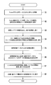
- FIG. 11 is a flowchart for explaining the operation of the CPU 16 of FIG. Assume that the user selects a reference image to be used in the Fusion function in the start step of FIG. In step S ⁇ b> 1, when the operator operates the operation unit 19 and presses the Fusion button, the input determination unit 41 determines the type of the input button and provides information to the controller 42.
- step S2 the controller 42 causes the mode change processing unit 44 to change the mode to the Fusion function based on the information from the input determination unit 41.
- the controller 42 passes the information on the purpose of diagnosis stored in the system information table 171 and information on the type of the selected probe to the mode conversion processing unit 44.
- the mode change processing unit 44 In the next step S3, the mode change processing unit 44 generates information such as a screen layout accompanying the mode change and passes it to the display processing unit 43.
- the mode change processing unit 44 passes the up / down / left / right inverted display information of the echo image, the probe type, and the diagnostic purpose information to the reference image forming unit 45.
- step S5 the reference image forming unit 45 constructs a three-dimensional image based on the reference image data read from the image database 15.
- step S6 the reference image forming unit 45 performs a three-dimensional process based on the cross-sectional direction data from the database 172 based on the probe type and the diagnostic purpose information together with the process for displaying the reference image.
- the cross-section extraction angle of CT / MRI image data is calculated.
- step S7 the reference image forming unit 45 calculates the display direction of the image using the up / down / left / right inverted display information and the screen layout information.
- step S8 the reference image forming unit 45 forms a cross-sectional image configured based on the calculations in steps S6 and S7 as a reference image, outputs it to the synthesizing unit 46, and displays it on the monitor 21 for processing. End (end).
- the cross-sectional direction of the reference image is set according to the diagnostic purpose of the subject and the type of the ultrasonic probe to be used. Can be set to a desired direction. Therefore, the operator can display the ultrasonic image and the reference image corresponding to the ultrasonic image by pressing the Fusion button, and can reduce the operation procedure.
- the reference image can be rotated to an appropriate angle, and an image suitable for diagnosis can be displayed.
Landscapes
- Health & Medical Sciences (AREA)
- Life Sciences & Earth Sciences (AREA)
- Engineering & Computer Science (AREA)
- Medical Informatics (AREA)
- Biomedical Technology (AREA)
- Public Health (AREA)
- General Health & Medical Sciences (AREA)
- Pathology (AREA)
- Animal Behavior & Ethology (AREA)
- Veterinary Medicine (AREA)
- Heart & Thoracic Surgery (AREA)
- Nuclear Medicine, Radiotherapy & Molecular Imaging (AREA)
- Molecular Biology (AREA)
- Surgery (AREA)
- Biophysics (AREA)
- Physics & Mathematics (AREA)
- Radiology & Medical Imaging (AREA)
- Computer Vision & Pattern Recognition (AREA)
- High Energy & Nuclear Physics (AREA)
- Optics & Photonics (AREA)
- Data Mining & Analysis (AREA)
- Databases & Information Systems (AREA)
- Epidemiology (AREA)
- Primary Health Care (AREA)
- Ultra Sonic Daignosis Equipment (AREA)
- Cardiology (AREA)
- Computer Graphics (AREA)
- General Engineering & Computer Science (AREA)
Priority Applications (1)
| Application Number | Priority Date | Filing Date | Title |
|---|---|---|---|
| US14/963,793 US20160095581A1 (en) | 2013-06-11 | 2015-12-09 | Ultrasonic diagnosis apparatus |
Applications Claiming Priority (2)
| Application Number | Priority Date | Filing Date | Title |
|---|---|---|---|
| JP2013122693A JP6162493B2 (ja) | 2013-06-11 | 2013-06-11 | 超音波診断装置 |
| JP2013-122693 | 2013-06-11 |
Related Child Applications (1)
| Application Number | Title | Priority Date | Filing Date |
|---|---|---|---|
| US14/963,793 Continuation US20160095581A1 (en) | 2013-06-11 | 2015-12-09 | Ultrasonic diagnosis apparatus |
Publications (1)
| Publication Number | Publication Date |
|---|---|
| WO2014199631A1 true WO2014199631A1 (ja) | 2014-12-18 |
Family
ID=52021943
Family Applications (1)
| Application Number | Title | Priority Date | Filing Date |
|---|---|---|---|
| PCT/JP2014/003100 Ceased WO2014199631A1 (ja) | 2013-06-11 | 2014-06-10 | 超音波診断装置 |
Country Status (3)
| Country | Link |
|---|---|
| US (1) | US20160095581A1 (enExample) |
| JP (1) | JP6162493B2 (enExample) |
| WO (1) | WO2014199631A1 (enExample) |
Families Citing this family (10)
| Publication number | Priority date | Publication date | Assignee | Title |
|---|---|---|---|---|
| JP2019503268A (ja) * | 2016-01-29 | 2019-02-07 | ノーブル センサーズ、エルエルシー | 位置と関係付けられた超音波撮像 |
| JP6873647B2 (ja) * | 2016-09-30 | 2021-05-19 | キヤノンメディカルシステムズ株式会社 | 超音波診断装置および超音波診断支援プログラム |
| JP6976869B2 (ja) * | 2018-01-15 | 2021-12-08 | キヤノンメディカルシステムズ株式会社 | 超音波診断装置及びその制御プログラム |
| CN109350111A (zh) * | 2018-10-08 | 2019-02-19 | 史建玲 | 一种用于超声的影像数据整合系统及方法 |
| CN109717906B (zh) * | 2019-02-23 | 2020-05-08 | 广州莲印医疗科技有限公司 | 一种胎头方向测量装置及其方法 |
| KR102512104B1 (ko) * | 2020-05-07 | 2023-03-22 | 한국과학기술연구원 | 3차원 초음파 이미지 생성 장치 및 방법 |
| JP7602929B2 (ja) * | 2021-02-16 | 2024-12-19 | キヤノンメディカルシステムズ株式会社 | 画像処理装置 |
| JP7781540B2 (ja) * | 2021-05-14 | 2025-12-08 | キヤノン株式会社 | 超音波画像処理装置およびプログラム |
| CN113243933A (zh) * | 2021-05-20 | 2021-08-13 | 张涛 | 一种远程超声诊断系统及使用方法 |
| JPWO2022270180A1 (enExample) | 2021-06-24 | 2022-12-29 |
Citations (5)
| Publication number | Priority date | Publication date | Assignee | Title |
|---|---|---|---|---|
| JP2000185036A (ja) * | 1998-12-24 | 2000-07-04 | Toshiba Corp | 医用画像表示装置 |
| JP2006167267A (ja) * | 2004-12-17 | 2006-06-29 | Hitachi Medical Corp | 超音波診断装置 |
| JP2008188417A (ja) * | 2007-01-11 | 2008-08-21 | Toshiba Corp | 三次元画像診断システム |
| JP2012061261A (ja) * | 2010-09-17 | 2012-03-29 | Toshiba Corp | 超音波診断装置、医用画像処理装置および医用画像処理プログラム |
| JP2012213558A (ja) * | 2011-04-01 | 2012-11-08 | Canon Inc | 画像処理装置、画像処理方法およびプログラム |
Family Cites Families (10)
| Publication number | Priority date | Publication date | Assignee | Title |
|---|---|---|---|---|
| US5615678A (en) * | 1994-11-25 | 1997-04-01 | General Electric Company | Integral auto-selecting yoke/transducer connector for ultrasound transducer probe |
| JP2003260056A (ja) * | 2002-03-08 | 2003-09-16 | Toshiba Corp | 超音波診断装置 |
| JP4167162B2 (ja) * | 2003-10-14 | 2008-10-15 | アロカ株式会社 | 超音波診断装置 |
| US20050228617A1 (en) * | 2004-04-02 | 2005-10-13 | Scott Kerwin | Methods and systems for tracking probe use |
| ATE404951T1 (de) * | 2004-10-01 | 2008-08-15 | Medcom Ges Fuer Medizinische B | Registrierung eines ultraschallbildes mit einem bild aus einem 3d-scan, beispielsweise von einer computertomographie (ct) oder magnetspintomographie (mr) |
| US20070255139A1 (en) * | 2006-04-27 | 2007-11-01 | General Electric Company | User interface for automatic multi-plane imaging ultrasound system |
| EP2047433A2 (en) * | 2006-07-25 | 2009-04-15 | Koninklijke Philips Electronics N.V. | Method and apparatus for curved multi-slice display |
| US8126239B2 (en) * | 2006-10-20 | 2012-02-28 | Siemens Aktiengesellschaft | Registering 2D and 3D data using 3D ultrasound data |
| EP2548514A4 (en) * | 2010-03-19 | 2013-07-31 | Hitachi Medical Corp | ULTRASONIC DIAGNOSIS DEVICE AND METHOD FOR DISPLAYING ULTRASONIC IMAGES |
| US9610063B2 (en) * | 2010-03-26 | 2017-04-04 | The Johns Hopkins University | Methods and apparatus for ultrasound strain imaging |
-
2013
- 2013-06-11 JP JP2013122693A patent/JP6162493B2/ja active Active
-
2014
- 2014-06-10 WO PCT/JP2014/003100 patent/WO2014199631A1/ja not_active Ceased
-
2015
- 2015-12-09 US US14/963,793 patent/US20160095581A1/en not_active Abandoned
Patent Citations (5)
| Publication number | Priority date | Publication date | Assignee | Title |
|---|---|---|---|---|
| JP2000185036A (ja) * | 1998-12-24 | 2000-07-04 | Toshiba Corp | 医用画像表示装置 |
| JP2006167267A (ja) * | 2004-12-17 | 2006-06-29 | Hitachi Medical Corp | 超音波診断装置 |
| JP2008188417A (ja) * | 2007-01-11 | 2008-08-21 | Toshiba Corp | 三次元画像診断システム |
| JP2012061261A (ja) * | 2010-09-17 | 2012-03-29 | Toshiba Corp | 超音波診断装置、医用画像処理装置および医用画像処理プログラム |
| JP2012213558A (ja) * | 2011-04-01 | 2012-11-08 | Canon Inc | 画像処理装置、画像処理方法およびプログラム |
Also Published As
| Publication number | Publication date |
|---|---|
| JP2014239731A (ja) | 2014-12-25 |
| JP6162493B2 (ja) | 2017-07-12 |
| US20160095581A1 (en) | 2016-04-07 |
Similar Documents
| Publication | Publication Date | Title |
|---|---|---|
| JP6162493B2 (ja) | 超音波診断装置 | |
| KR102452998B1 (ko) | 초음파 진단 장치 | |
| JP6238651B2 (ja) | 超音波診断装置及び画像処理方法 | |
| US11653897B2 (en) | Ultrasonic diagnostic apparatus, scan support method, and medical image processing apparatus | |
| JP4088104B2 (ja) | 超音波診断装置 | |
| JP6282934B2 (ja) | 超音波診断装置及び医用画像診断装置 | |
| KR101705120B1 (ko) | 자가 진단 및 원격 진단을 위한 초음파 진단 장치 및 초음파 진단 장치의 동작 방법 | |
| KR102255417B1 (ko) | 초음파 진단 장치 및 그에 따른 초음파 영상의 디스플레이 방법 | |
| JP6956483B2 (ja) | 超音波診断装置、及び走査支援プログラム | |
| JP6125380B2 (ja) | 超音波診断装置、医用画像処理装置及び画像処理プログラム | |
| CN102266236B (zh) | 超声波诊断装置以及图像信息管理装置 | |
| JP2016067559A (ja) | 医用画像診断装置、画像処理装置、画像処理方法及び画像処理プログラム | |
| KR20240131950A (ko) | 초음파 장치 및 그 제어방법 | |
| JP6720001B2 (ja) | 超音波診断装置、及び医用画像処理装置 | |
| US10298849B2 (en) | Imaging apparatus and control method thereof | |
| JP5134932B2 (ja) | 超音波診断装置及び超音波診断装置の制御プログラム | |
| JP2019093123A (ja) | 医用画像診断装置及び医用画像処理装置 | |
| JP2019195447A (ja) | 超音波診断装置及び医用情報処理プログラム | |
| JP2013118998A (ja) | 医用画像診断装置、超音波診断装置及びプログラム | |
| US20130144168A1 (en) | Ultrasound diagnostic apparatus and computer program product | |
| JP2015136445A (ja) | 超音波診断装置、画像処理装置及びプログラム | |
| JP5597497B2 (ja) | 超音波診断装置、医用画像処理装置および医用画像処理プログラム | |
| JP6419413B2 (ja) | 超音波診断装置及び位置合わせプログラム | |
| JP2014239841A (ja) | 超音波診断装置、医用画像処理装置及び制御プログラム | |
| JP2022012486A (ja) | 医用画像処理装置及び医用画像処理システム |
Legal Events
| Date | Code | Title | Description |
|---|---|---|---|
| 121 | Ep: the epo has been informed by wipo that ep was designated in this application |
Ref document number: 14811172 Country of ref document: EP Kind code of ref document: A1 |
|
| NENP | Non-entry into the national phase |
Ref country code: DE |
|
| 122 | Ep: pct application non-entry in european phase |
Ref document number: 14811172 Country of ref document: EP Kind code of ref document: A1 |