WO2014199631A1 - Ultrasonic diagnostic device - Google Patents
Ultrasonic diagnostic device Download PDFInfo
- Publication number
- WO2014199631A1 WO2014199631A1 PCT/JP2014/003100 JP2014003100W WO2014199631A1 WO 2014199631 A1 WO2014199631 A1 WO 2014199631A1 JP 2014003100 W JP2014003100 W JP 2014003100W WO 2014199631 A1 WO2014199631 A1 WO 2014199631A1
- Authority
- WO
- WIPO (PCT)
- Prior art keywords
- image
- ultrasonic
- reference image
- cross
- unit
- Prior art date
Links
Images


Classifications
-
- A—HUMAN NECESSITIES
- A61—MEDICAL OR VETERINARY SCIENCE; HYGIENE
- A61B—DIAGNOSIS; SURGERY; IDENTIFICATION
- A61B8/00—Diagnosis using ultrasonic, sonic or infrasonic waves
- A61B8/52—Devices using data or image processing specially adapted for diagnosis using ultrasonic, sonic or infrasonic waves
- A61B8/5215—Devices using data or image processing specially adapted for diagnosis using ultrasonic, sonic or infrasonic waves involving processing of medical diagnostic data
-
- A—HUMAN NECESSITIES
- A61—MEDICAL OR VETERINARY SCIENCE; HYGIENE
- A61B—DIAGNOSIS; SURGERY; IDENTIFICATION
- A61B6/00—Apparatus for radiation diagnosis, e.g. combined with radiation therapy equipment
- A61B6/52—Devices using data or image processing specially adapted for radiation diagnosis
- A61B6/5211—Devices using data or image processing specially adapted for radiation diagnosis involving processing of medical diagnostic data
- A61B6/5229—Devices using data or image processing specially adapted for radiation diagnosis involving processing of medical diagnostic data combining image data of a patient, e.g. combining a functional image with an anatomical image
- A61B6/5247—Devices using data or image processing specially adapted for radiation diagnosis involving processing of medical diagnostic data combining image data of a patient, e.g. combining a functional image with an anatomical image combining images from an ionising-radiation diagnostic technique and a non-ionising radiation diagnostic technique, e.g. X-ray and ultrasound
-
- A—HUMAN NECESSITIES
- A61—MEDICAL OR VETERINARY SCIENCE; HYGIENE
- A61B—DIAGNOSIS; SURGERY; IDENTIFICATION
- A61B8/00—Diagnosis using ultrasonic, sonic or infrasonic waves
- A61B8/42—Details of probe positioning or probe attachment to the patient
- A61B8/4245—Details of probe positioning or probe attachment to the patient involving determining the position of the probe, e.g. with respect to an external reference frame or to the patient
- A61B8/4254—Details of probe positioning or probe attachment to the patient involving determining the position of the probe, e.g. with respect to an external reference frame or to the patient using sensors mounted on the probe
-
- A—HUMAN NECESSITIES
- A61—MEDICAL OR VETERINARY SCIENCE; HYGIENE
- A61B—DIAGNOSIS; SURGERY; IDENTIFICATION
- A61B8/00—Diagnosis using ultrasonic, sonic or infrasonic waves
- A61B8/52—Devices using data or image processing specially adapted for diagnosis using ultrasonic, sonic or infrasonic waves
- A61B8/5215—Devices using data or image processing specially adapted for diagnosis using ultrasonic, sonic or infrasonic waves involving processing of medical diagnostic data
- A61B8/5238—Devices using data or image processing specially adapted for diagnosis using ultrasonic, sonic or infrasonic waves involving processing of medical diagnostic data for combining image data of patient, e.g. merging several images from different acquisition modes into one image
- A61B8/5261—Devices using data or image processing specially adapted for diagnosis using ultrasonic, sonic or infrasonic waves involving processing of medical diagnostic data for combining image data of patient, e.g. merging several images from different acquisition modes into one image combining images from different diagnostic modalities, e.g. ultrasound and X-ray
-
- G—PHYSICS
- G16—INFORMATION AND COMMUNICATION TECHNOLOGY [ICT] SPECIALLY ADAPTED FOR SPECIFIC APPLICATION FIELDS
- G16H—HEALTHCARE INFORMATICS, i.e. INFORMATION AND COMMUNICATION TECHNOLOGY [ICT] SPECIALLY ADAPTED FOR THE HANDLING OR PROCESSING OF MEDICAL OR HEALTHCARE DATA
- G16H50/00—ICT specially adapted for medical diagnosis, medical simulation or medical data mining; ICT specially adapted for detecting, monitoring or modelling epidemics or pandemics
- G16H50/20—ICT specially adapted for medical diagnosis, medical simulation or medical data mining; ICT specially adapted for detecting, monitoring or modelling epidemics or pandemics for computer-aided diagnosis, e.g. based on medical expert systems
-
- A—HUMAN NECESSITIES
- A61—MEDICAL OR VETERINARY SCIENCE; HYGIENE
- A61B—DIAGNOSIS; SURGERY; IDENTIFICATION
- A61B6/00—Apparatus for radiation diagnosis, e.g. combined with radiation therapy equipment
- A61B6/50—Clinical applications
- A61B6/503—Clinical applications involving diagnosis of heart
-
- A—HUMAN NECESSITIES
- A61—MEDICAL OR VETERINARY SCIENCE; HYGIENE
- A61B—DIAGNOSIS; SURGERY; IDENTIFICATION
- A61B8/00—Diagnosis using ultrasonic, sonic or infrasonic waves
- A61B8/08—Detecting organic movements or changes, e.g. tumours, cysts, swellings
- A61B8/0808—Detecting organic movements or changes, e.g. tumours, cysts, swellings for diagnosis of the brain
-
- A—HUMAN NECESSITIES
- A61—MEDICAL OR VETERINARY SCIENCE; HYGIENE
- A61B—DIAGNOSIS; SURGERY; IDENTIFICATION
- A61B8/00—Diagnosis using ultrasonic, sonic or infrasonic waves
- A61B8/08—Detecting organic movements or changes, e.g. tumours, cysts, swellings
- A61B8/0883—Detecting organic movements or changes, e.g. tumours, cysts, swellings for diagnosis of the heart
-
- A—HUMAN NECESSITIES
- A61—MEDICAL OR VETERINARY SCIENCE; HYGIENE
- A61B—DIAGNOSIS; SURGERY; IDENTIFICATION
- A61B8/00—Diagnosis using ultrasonic, sonic or infrasonic waves
- A61B8/44—Constructional features of the ultrasonic, sonic or infrasonic diagnostic device
- A61B8/4444—Constructional features of the ultrasonic, sonic or infrasonic diagnostic device related to the probe
-
- A—HUMAN NECESSITIES
- A61—MEDICAL OR VETERINARY SCIENCE; HYGIENE
- A61B—DIAGNOSIS; SURGERY; IDENTIFICATION
- A61B8/00—Diagnosis using ultrasonic, sonic or infrasonic waves
- A61B8/46—Ultrasonic, sonic or infrasonic diagnostic devices with special arrangements for interfacing with the operator or the patient
- A61B8/461—Displaying means of special interest
- A61B8/463—Displaying means of special interest characterised by displaying multiple images or images and diagnostic data on one display
-
- A—HUMAN NECESSITIES
- A61—MEDICAL OR VETERINARY SCIENCE; HYGIENE
- A61B—DIAGNOSIS; SURGERY; IDENTIFICATION
- A61B8/00—Diagnosis using ultrasonic, sonic or infrasonic waves
- A61B8/46—Ultrasonic, sonic or infrasonic diagnostic devices with special arrangements for interfacing with the operator or the patient
- A61B8/461—Displaying means of special interest
- A61B8/466—Displaying means of special interest adapted to display 3D data
Definitions
- Embodiments described herein relate generally to an ultrasonic diagnostic apparatus, and to an ultrasonic diagnostic apparatus that displays an image acquired by a medical image diagnostic apparatus together with an ultrasonic image as a reference image.
- an ultrasonic diagnostic apparatus is used as a medical apparatus.
- the ultrasonic diagnostic apparatus can be connected to various modalities such as an X-ray CT apparatus (X-ray computed tomography apparatus) and an MRI apparatus (magnetic resonance imaging apparatus) via a hospital network. Diagnosis and treatment of diseases are supported using images acquired by other medical image diagnostic apparatuses.
- a CT image of the same cross section as an ultrasonic image is obtained by aligning a cross section scanned by an ultrasonic probe with a CT image or MRI image in which a lesion is detected using a magnetic position sensor.
- an ultrasonic diagnostic apparatus that displays an MRI image as a reference image and navigates an ultrasonic probe to the position of a lesion is known.
- the function of aligning and displaying the ultrasonic image (echo image) and the reference image (hereinafter referred to as the “Fusion function”) is an indispensable function for medical treatment of initial cancer.
- the magnetic position sensor is provided in a magnetic field formed by a transmitter, for example, and is attached to the ultrasonic probe.
- the problem to be solved by the invention is to provide an ultrasonic diagnostic apparatus that sets the orientation of the cross section of the initial display of the reference image in accordance with the diagnostic purpose and the type of probe.
- An ultrasonic diagnostic apparatus is attached to an ultrasonic image generation unit that generates an ultrasonic image based on a reception signal from an ultrasonic probe that transmits / receives ultrasonic waves to / from a subject, and the ultrasonic probe
- a position information acquisition unit that acquires position information of the ultrasonic probe in a three-dimensional space
- an image acquisition unit that acquires image data and obtains a reference image corresponding to the ultrasonic image
- a reference image forming unit that specifies a cross-sectional direction in which the reference image is to be displayed in accordance with at least one of information on the diagnostic purpose of the specimen and information on the type of ultrasonic probe, and forms a reference image in the specified cross-sectional direction
- a display unit for displaying a reference image formed by the reference image forming unit and an ultrasonic image from the ultrasonic image generating unit.
- FIG. 1 is a block diagram showing a schematic configuration of an ultrasonic diagnostic apparatus according to an embodiment.
- Explanatory drawing which shows arrangement
- Explanatory drawing which shows the example of a display of the reference image and ultrasonic image in embodiment.
- the block diagram which shows the structure of CPU and its periphery part in embodiment.
- Explanatory drawing which shows schematically the direction of the cross section in embodiment.
- Explanatory drawing which shows the mode at the time of the diagnosis of the prostate in embodiment.
- Explanatory drawing which shows the rotation process of the reference image in embodiment.
- Explanatory drawing which shows the scanning example of the abdomen and the heart by the probe in embodiment.
- Explanatory drawing which shows roughly the apex four-chamber cross section in embodiment.
- FIG. 1 is a block diagram illustrating a schematic configuration of an ultrasonic diagnostic apparatus 10 according to an embodiment.
- a main body 100 of an ultrasonic diagnostic apparatus includes an ultrasonic probe 11 that transmits / receives ultrasonic waves to / from a subject (not shown), and an ultrasonic probe 11 that drives the ultrasonic probe 11 to A transmission / reception unit 12 that performs acoustic wave scanning, and a data processing unit 13 that processes reception signals obtained by the transmission / reception unit 2 to generate image data such as B-mode image data and Doppler image data.
- the main body 100 collects and stores the image generation unit 14 that generates two-dimensional image data based on the image data output from the data processing unit 13 and the image data generated by the image generation unit 14.
- An image database 15 is provided.
- the main body 100 further includes a central processing unit (CPU) 16 that controls the entire apparatus, a storage unit 17, and an interface unit 18 for connecting the main body 100 to the network 22.
- An operation unit 19 for inputting various command signals and a position information acquisition unit 20 are connected to the interface 18 unit.
- the main body 100 is connected to a monitor (display unit) 21 that displays an image generated by the image generation unit 14.
- the CPU 16 and each circuit unit are connected via a bus line 101.
- the interface 18 can be connected to the network 22, and the image data acquired by the ultrasonic diagnostic apparatus 10 can be stored in the external medical server 23 via the network 22.
- the network 22 is connected to a medical image diagnostic apparatus 24 such as an MRI apparatus, an X-ray CT apparatus, or a nuclear medicine diagnostic apparatus.
- the medical image data acquired by the medical image diagnostic apparatus 24 is stored in the medical server 23. be able to.
- the ultrasonic probe 11 performs ultrasonic wave transmission / reception by bringing its tip surface into contact with the body surface of the subject, and has, for example, a plurality of piezoelectric vibrators arranged one-dimensionally.
- the piezoelectric vibrator is an electroacoustic transducer, which converts an ultrasonic drive signal into a transmission ultrasonic wave during transmission, and converts a reception ultrasonic wave from the subject into an ultrasonic reception signal during reception.
- the ultrasonic probe 11 is a sector type, a linear type, a convex type or the like. In the following description, the ultrasonic probe 11 may be simply referred to as a probe.
- the scissor transmission / reception unit 12 includes a transmission unit 121 that generates an ultrasonic drive signal and a reception unit 122 that processes an ultrasonic reception signal obtained from the ultrasonic probe 1.
- the transmission unit 121 generates an ultrasonic drive signal and outputs it to the probe 11, and the reception unit 122 outputs an ultrasonic reception signal (echo signal) from the piezoelectric vibrator to the data processing unit 13.
- the eyelid data processing unit 13 includes a B-mode processing unit 131 that generates B-mode image data from a signal output from the transmission / reception unit 12, a Doppler processing unit 132 that generates Doppler image data, and the like.
- the B mode processing unit 131 performs envelope detection on the signal from the transmission / reception unit 12 and then performs logarithmic conversion, converts the logarithmically converted signal into a digital signal, generates B mode image data, and generates the image generation unit 14. Output to.
- the Doppler processing unit 132 detects the Doppler shift frequency for the signal from the transmission / reception unit 12 and converts it to a digital signal, extracts blood flow and tissue due to the Doppler effect, generates Doppler data, and generates the image generation unit 14. Output to.
- the image generation unit 14 generates an ultrasonic image using the B-mode image data, Doppler image data, etc. output from the data processing unit 13.
- the image generation unit 14 includes a DSC (Digital Scan Converter), performs scan conversion of the generated image data, and generates an ultrasonic image (B-mode image or Doppler image) that can be displayed on the monitor 21. Therefore, the ultrasonic probe 11, the transmission / reception unit 12, the data processing unit 13, and the image generation unit 14 constitute an ultrasonic image generation unit that generates an ultrasonic image.
- DSC Digital Scan Converter
- the image database 15 stores the image data generated by the image generation unit 14.
- the image database 15 includes three-dimensional image data taken by another medical image diagnostic apparatus 24 (such as an MRI apparatus or an X-ray CT apparatus) via the interface unit 18, for example, data such as an MPR (Multi-Planer Reconstruction) image. Is acquired and memorized.
- the acquired three-dimensional image data can be used to obtain a reference image (described later) corresponding to the ultrasonic image. Therefore, the image database 15 and the interface unit 18 constitute an image acquisition unit that acquires three-dimensional image data.
- the CPU 16 controls the entire ultrasound diagnostic apparatus 10 and executes various processes. For example, the transmission / reception unit 12, the data processing unit 13, and the image generation unit 14 are controlled based on various setting requests input from the operation unit 19 and various control programs and various setting information read from the storage unit 17. Further, control is performed so that the ultrasonic image stored in the image database 15 is displayed on the monitor 21.
- the storage unit 17 stores various data such as a control program for performing ultrasonic transmission / reception, image processing and display processing, diagnostic information (for example, subject ID, doctor's findings, etc.), diagnostic protocol, and the like. Furthermore, the storage unit 17 is also used for storing images stored in the image database 15 as necessary. The storage unit 17 stores various information used for processing by the CPU 16.
- the interface unit 18 is an interface that controls the exchange of various information between the operation unit 19, the position information acquisition unit 20 and the network 22, and the main body 100.
- the operation unit 19 includes input devices such as various switches, a keyboard, a trackball, a mouse, and a touch command screen, receives various setting requests from an operator, and transfers various setting requests to the main body 100. For example, the operation unit 19 receives various operations related to the alignment between the ultrasonic image and the X-ray CT image.
- the monitor 21 displays a GUI (Graphical User Interface) for the operator of the ultrasonic diagnostic apparatus 10 to input various setting requests by operating the operation unit 19, or an ultrasonic image generated in the main body 100, Line CT images and the like are displayed in parallel.
- GUI Graphic User Interface
- the CPU 16 for example, conforms to the DICOM (Digital Imaging and Communications in Medicine) standard and transmits the three-dimensional image data of another medical image diagnostic apparatus 24 (for example, an X-ray CT apparatus, an MRI apparatus, etc.) to the network 22. Send and receive via.
- DICOM Digital Imaging and Communications in Medicine
- three-dimensional image data such as an X-ray CT apparatus and an MRI apparatus can be stored in a storage medium such as a CD, DVD, or USB, and the data stored in the storage medium can be taken into the ultrasonic diagnostic apparatus 10. .
- the eyelid position information acquisition unit 20 acquires position information indicating where the ultrasonic probe 11 is located, for example.
- the position information acquisition device 20 for example, a magnetic sensor, an infrared sensor, an optical sensor, a camera, or the like is used. In the following description, an example using a magnetic sensor will be described.
- the position information acquisition unit 20 when the subject is scanned by the ultrasonic probe 11, a CT image or MRI image in which a lesion is detected is displayed as a reference image, and the position of the cross section to be scanned and the position of the reference image is the same. In order to match, a position information acquisition unit 20 is provided.
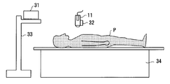
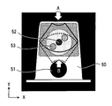
- FIG. 2 is an explanatory diagram schematically showing the arrangement of position sensors in the position information acquisition unit 20. That is, the position sensor system of FIG. 2 includes a transmitter 31 (transmitter) and a position sensor (receiver) 32.
- the transmitter 31 is, for example, a magnetic transmitter, is attached to a pole 33 or the like at a fixed position near the bed 34, and transmits a reference signal.
- the transmitter 31 forms a magnetic field toward the outside centering on its own device.
- the transmitter 31 may be attached to the tip of an arm attached to the ultrasonic diagnostic apparatus main body, or may be attached to the tip of an arm of a movable pole stand.
- a position sensor 32 made of, for example, a magnetic sensor is attached to a three-dimensional magnetic field formed by the transmitter 31 in an area where the magnetism transmitted from the transmitter 31 can be received.
- the position sensor 32 may be simply referred to as the sensor 32.
- the sensor 32 is attached to the ultrasonic probe 11 and receives the reference signal from the transmitter 31 to acquire position information in the three-dimensional space and detect the position and posture (tilt) of the ultrasonic probe 11.
- the position information of the sensor 32 is supplied to the CPU 16 via the interface unit 18.
- the CPU 16 aligns an arbitrary cross section of the three-dimensional image data generated by the medical image diagnostic apparatus 24 with a cross section scanned by the ultrasonic probe 11. Then, the 3D image data is associated with the 3D space.
- the CPU 16 acquires the currently displayed ultrasonic image (two-dimensional image) at which position and angle of the subject P based on the detection result of the sensor 32. Calculate what you did.
- the transmitter 31 serves as a reference for the position / angle information (the origin of the coordinate system).
- the volume data of the CT image or MRI image is read into the ultrasonic diagnostic apparatus 10 and the MPR image is displayed.
- the reference image (MPR image) and the ultrasonic image are displayed on the same screen, and the angle adjustment for matching the scanning direction of the ultrasonic probe 11 to the direction corresponding to the orientation (Orientation) of the cross section of the reference image, and the reference image A point is set on a mark observable in both the ultrasonic image and the ultrasonic image, and alignment is performed by mark alignment that matches the position. That is, by associating the direction and coordinates of the position sensor 32 with the coordinates of the volume data, a two-dimensional image at the same position as the current scanning plane of the ultrasonic probe 11 can be generated from the volume data of other modalities. It is possible to display an ultrasonic image that changes with the movement of the ultrasonic probe and an MPR image of the same cross section.
- the same cross section as the ultrasonic image that changes with the movement of the probe 11 can be displayed as an MPR image. Therefore, a tumor or the like that is difficult to confirm with an ultrasonic image can be confirmed with an MPR image.
- the function of aligning and combining the ultrasonic image (echo image) and the reference image for display is referred to as a “Fusion” function in the following description.
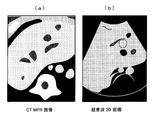
- FIG. 3 shows a reference image (a) and an ultrasonic image (b) after alignment.
- the reference image (a) for example, an MPR image (Multi-Planer Reconstruction image) generated from volume data collected by an X-ray CT apparatus is used.
- an image acquired by an MRI apparatus can be used.
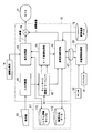
- FIG. 4 is a block diagram showing the configuration of the CPU 16 and its peripheral part, which are characteristic parts of the present embodiment.
- the CPU 16 includes an input determination unit 41, a controller 42 including control software, a display processing unit 43, a mode conversion processing unit 44, a reference image forming unit 45, and a combining unit 46.
- the storage unit 17 includes a system information table 171 in which information on the type of the selected probe and information for diagnostic purposes are stored, and a database 172 in which cross-sectional direction data is stored.
- the image database 15 is for medical use other than the ultrasonic diagnostic apparatus 10. A three-dimensional image such as a CT image or an MRI image acquired from the diagnostic imaging apparatus 24 is stored.
- the system information table 171 is connected to the display processing unit 43, and the database 172 is connected to the reference image forming unit 45.
- the image database 15 is connected to the reference image forming unit 45.
- the input determination unit 41 is connected to the operation unit 19, determines what input operation is performed on the operation unit 19, and supplies the determination information to the controller 32.
- the controller 42 is connected to the mode conversion processing unit 44 and the reference image forming unit 45, and the mode conversion processing unit 44 is connected to the display processing unit 43 and the reference image forming unit 45.
- the reference image forming unit 45 is connected to the position information acquisition unit 20 via the cable 47, and the reference image formed by the reference image forming unit 45 and the echo image processed by the display processing unit 43 are combined by the combining unit 46. And output to the monitor 21.
- the application of the Fusion function is based on the premise that the ultrasonic probe 11 is applied to the body surface, and the diagnostic purpose (Exam ⁇ Type) is mainly the abdomen. .
- the first method is a method in which the probe is applied from the body surface of the subject as in the conventional diagnosis of the abdomen, and is mainly used for observing the state of prostatic hypertrophy.
- the probe to be used is a convex probe for body surface (for example, PVT-375BT manufactured by Toshiba).
- the second method is a method of observing the prostate through a wall of the rectum by inserting a probe from the anus, and is mainly used for observing prostate cancer. This second method may also be used for observation of prostate enlargement.
- the probe used is a convex probe in a body cavity (for example, PVT-781VT manufactured by Toshiba).
- MRI images or CT images are often used as the reference image for the Fusion function, and the orientation of the cross-section (Orientation) of the reference image is often used axially. That is, in the Fusion function, in the initial alignment with the MRI image, it is necessary to match both the angle and the position, but at this time, the operation is often performed on the basis of the axial section. This is because the operator can easily understand.
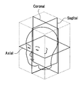
- FIG. 5 is an explanatory view schematically showing the direction of a cross section in the CT apparatus and the MRI apparatus.
- the reference cross section directions such as a body axis cross section (Axial) horizontal to the subject, a vertical cross section (Sagittal), and a cross section (Coronal) are generally known. ing.
- FIG. 6 is an explanatory diagram showing a state of prostate diagnosis.
- a phantom is used instead of the subject, and an axial cross section of the CT image 50 is shown.
- 51 is a rectal hole
- 52 is the urethra
- 53 is a tumor.
- ultrasonic imaging is performed by applying a probe from the body surface (in the direction of arrow A) as indicated by a thick solid line.
- ultrasonic imaging is performed by applying a probe from within a body cavity (state inserted from the rectum: direction of arrow B).
- the orientation of the cross section of the reference image composed of the CT image 51 is axial, but the positional relationship of the obtained echo images when the ultrasonic probe 11 is applied from the body surface and when applied from the body cavity. Is different. Therefore, when observing from the rectal wall using the probe in the body cavity, the axial section of the reference image and the direction of the echo image may be reversed.
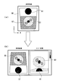
- FIG. 7 is an explanatory diagram showing a general rotation process of a reference image.
- FIG. 7A shows a reference image 50 (CT image) read into the image database.
- CT image reference image
- FIG. 7B a reference image 50 and an echo image 60 taken by the ultrasonic apparatus are displayed side by side.
- 61 is a rectal hole
- 62 is a urethra
- 63 is a tumor.
- the reference image 50 is rotated 180 degrees with respect to the X axis as shown in FIG. 7C.
- the operation direction of the probe is restricted due to the structure of the human body, and therefore the insertion angle is inclined to some extent with respect to the axial axis (for example, it tends to be inclined about 30 degrees). is there). Therefore, when the reference image is rotated in prostate diagnosis, an image suitable for diagnosis is rotated by 150 degrees (180-30 degrees).
- the direction of the cross section of the reference image is initialized in advance according to the diagnosis purpose (for example, diagnosis of the prostate, heart, viscera, etc.) and the reference image needs to be rotated, ultrasonic waves
- the rotation angle is initially set in accordance with the type of probe 11 (body surface probe, body cavity probe).
- the orientation and the rotation angle of the cross section of the reference image are automatically set by the initial setting.
- An adjusted reference image can be generated and displayed with the echo image.
- FIG. 8 is an explanatory diagram illustrating a reference image rotation process according to the embodiment.
- FIG. 8A shows a reference image 50 (CT image) read into the image database 15.
- CT image reference image
- FIG. 8B the reference image 50 and the echo image 60 photographed by the ultrasonic apparatus are displayed side by side.
- the reference image 50 displays an image of an axial section according to the initial setting, and displays an image obtained by rotating the reference image 50 by 150 degrees with respect to the X axis. Therefore, the operator can reduce time and labor without adjusting the reference image many times.
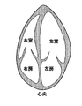
- the probe when diagnosing multiple parts with the same probe, it is better to change the direction of the cross section of the reference image depending on the purpose of diagnosis. For example, as shown in FIG. 9, when the sector probe is used, the probe is generally placed in the direction corresponding to the axial section in the abdominal scan, but in the cardiac scan, the apical four-chamber section is not axial but the axial section. It is easier to diagnose with the reference plane.
- the apex four-chamber cross section is a cross section suitable for observing the presence or absence of abnormalities in the right atrium right ventricle and the left atrium left ventricle. Often the probe is scanned as is done. Therefore, by initializing the direction of the cross section of the reference image so as to correspond to the four-chamber section of the apex, a reference image suitable for diagnosis can be displayed when the Fusion function is activated.
- a sputum system information table 171 shown in FIG. 4 and a database 172 storing cross-sectional direction data are added to the configuration of the ultrasonic diagnostic imaging apparatus 10, and an initial cross-section of the reference image is added to the reference image forming unit 45. And a process of changing the section direction data of the initial section of the reference image according to the button operation of the operator.
- the controller 42 sets and sets the cross-sectional direction of the reference image according to the diagnostic purpose and the type of ultrasonic probe to be used.
- the cross-sectional direction data is stored in the database 172. That is, the controller 42 constitutes a cross-sectional direction setting unit.
- the cross section of the reference image is axial, and the correction of the rotation angle of the cross section is zero.
- the cross section of the reference image is axial, and the correction of the rotation angle of the cross section is set to 150 degrees as the vertical rotation.
- 150 degrees is a total angle obtained by subtracting (returning) 30 degrees, which is an angle at which the probe 11 is inclined with respect to the axial plane, to a rotation angle of 180 degrees. Since the rotation in the vertical direction rotates around the X axis (horizontal axis) in the graphics coordinate system, it may be called an X-axis rotation amount of 150 degrees.
- the user In such a state, after the user selects a reference image to be used in the Fusion function, the user operates the operation unit 19 and presses the Fusion button for starting the Fusion function.
- the input determination unit 41 detects that the button has been pressed.
- the input determination unit 41 confirms the operation status of all buttons of the operation unit 19 at regular intervals. Therefore, the state change caused by pressing the Fusion button can be determined by the input determination unit 41, and the fact that the Fusion button has been pressed is passed to the controller.
- the controller 42 In response to the operation of the Fusion button, the controller 42 passes information indicating the probe type and diagnostic purpose information from the system information table 171 to the mode change processing unit 44 in order to set the operation mode to “Fusion”. .
- the mode change processing unit 44 needs to display the reference image in accordance with the mode change, the layout information of the monitor 21 for displaying the reference image, the information on the display direction of the echo image, and the information indicating the type of the probe. Information for diagnostic purposes is passed to the reference image forming unit 45.
- the reference image forming unit 45 reads a plurality of slice images from, for example, an MRI apparatus from the image database 15 and configures three-dimensional data. Next, based on information on the diagnostic purpose and the type of the probe, cross-sectional direction data used and corresponding to the probe is acquired from the database 172. For example, when the probe type is a convex probe in a body cavity, information on the X-axis rotation amount: 150 degrees is obtained.
- the reference image forming unit 45 sequentially acquires data from a position rotated about the X axis from the center of the data from the three-dimensional data of the constructed MRI image with the body surface as a reference, and forms a two-dimensional image.
- the data reading start position is the contact position of the probe with the subject. When the data is read in the Y-axis direction, images at positions away from the contact position are sequentially formed and become two-dimensional image data.
- the image forming unit 45 performs processing so that the two-dimensional reference image is displayed in a corresponding direction, and outputs the processed image to the combining unit 46.
- the synthesizing unit 46 synthesizes the echo image processed by the display processing unit 43 and the reference image formed by the reference image forming unit 45 and outputs them to the monitor 21. As shown in FIG. 8B, the monitor 21 displays the reference image side by side with the processed echo image.
- the operator changes the inclination of the reference image, it is transmitted from the operation unit 19 to the controller 42 via the input determination unit 41, and the controller 42 informs the reference image forming unit 45 of information about the rotation axis and information about the rotation amount. Send.
- the reference image forming unit 45 constructs and outputs a two-dimensional reference image from the three-dimensional data based on the rotation axis information and the rotation amount information.
- the save button of the operation unit 19 When the save button of the operation unit 19 is input to save the display direction changed by the operator, information indicating that the save button has been pressed is transmitted to the reference image forming unit 45 through the input determination unit 41 and the controller 42. Then, the reference image forming unit 45 updates and stores the cross-sectional direction data corresponding to the information of the selected probe in the database 172.
- the purpose of diagnosis is a heart examination
- the reference image is processed and displayed so that the direction of the cross-section of the reference image is an image corresponding to the cross-section of the apex.
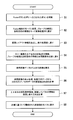
- FIG. 11 is a flowchart for explaining the operation of the CPU 16 of FIG. Assume that the user selects a reference image to be used in the Fusion function in the start step of FIG. In step S ⁇ b> 1, when the operator operates the operation unit 19 and presses the Fusion button, the input determination unit 41 determines the type of the input button and provides information to the controller 42.
- step S2 the controller 42 causes the mode change processing unit 44 to change the mode to the Fusion function based on the information from the input determination unit 41.
- the controller 42 passes the information on the purpose of diagnosis stored in the system information table 171 and information on the type of the selected probe to the mode conversion processing unit 44.
- the mode change processing unit 44 In the next step S3, the mode change processing unit 44 generates information such as a screen layout accompanying the mode change and passes it to the display processing unit 43.
- the mode change processing unit 44 passes the up / down / left / right inverted display information of the echo image, the probe type, and the diagnostic purpose information to the reference image forming unit 45.
- step S5 the reference image forming unit 45 constructs a three-dimensional image based on the reference image data read from the image database 15.
- step S6 the reference image forming unit 45 performs a three-dimensional process based on the cross-sectional direction data from the database 172 based on the probe type and the diagnostic purpose information together with the process for displaying the reference image.
- the cross-section extraction angle of CT / MRI image data is calculated.
- step S7 the reference image forming unit 45 calculates the display direction of the image using the up / down / left / right inverted display information and the screen layout information.
- step S8 the reference image forming unit 45 forms a cross-sectional image configured based on the calculations in steps S6 and S7 as a reference image, outputs it to the synthesizing unit 46, and displays it on the monitor 21 for processing. End (end).
- the cross-sectional direction of the reference image is set according to the diagnostic purpose of the subject and the type of the ultrasonic probe to be used. Can be set to a desired direction. Therefore, the operator can display the ultrasonic image and the reference image corresponding to the ultrasonic image by pressing the Fusion button, and can reduce the operation procedure.
- the reference image can be rotated to an appropriate angle, and an image suitable for diagnosis can be displayed.
Abstract
An ultrasonic diagnostic device according to an embodiment comprises: an ultrasonic image generation unit; a position information acquisition unit which includes a position sensor attached to an ultrasonic probe and acquires position information of the ultrasonic probe in a three-dimensional space; an image acquisition unit which acquires image data and obtains a reference image that corresponds to the ultrasonic image; a reference image formation unit which specifies a cross sectional direction to be displayed of the reference image according to at least one of information on diagnostic purpose of a subject and information on the type of the ultrasonic probe, and which forms a reference image of the specified cross sectional direction; and a display unit which displays the reference image formed by the reference image formation unit and the ultrasonic image from the ultrasonic image generation unit.
Description
本発明の実施形態は、超音波診断装置に係り、超音波画像とともに医用画像診断装置によって取得した画像を参照画像として表示する超音波診断装置に関する。
Embodiments described herein relate generally to an ultrasonic diagnostic apparatus, and to an ultrasonic diagnostic apparatus that displays an image acquired by a medical image diagnostic apparatus together with an ultrasonic image as a reference image.
従来、医用装置として超音波診断装置が使用されている。また超音波診断装置は、X線CT装置(X線コンピュータトモグラフィ装置)、MRI装置(磁気共鳴イメージング装置)等の様々なモダリティに病院内のネットワークを介して接続可能であり、超音波画像と他の医用画像診断装置で取得した画像を利用して疾患の診断及び治療を支援するようにしている。
Conventionally, an ultrasonic diagnostic apparatus is used as a medical apparatus. The ultrasonic diagnostic apparatus can be connected to various modalities such as an X-ray CT apparatus (X-ray computed tomography apparatus) and an MRI apparatus (magnetic resonance imaging apparatus) via a hospital network. Diagnosis and treatment of diseases are supported using images acquired by other medical image diagnostic apparatuses.
例えば、超音波プローブによって走査される断面と、病巣が検出されたCT画像又はMRI画像とを、磁気式の位置センサを用いて位置合わせし、超音波画像(エコー画像)と同じ断面のCT画像又はMRI画像を参照画像として表示し、病巣の位置に超音波プローブをナビゲートする超音波診断装置が知られている。
For example, a CT image of the same cross section as an ultrasonic image (echo image) is obtained by aligning a cross section scanned by an ultrasonic probe with a CT image or MRI image in which a lesion is detected using a magnetic position sensor. Alternatively, an ultrasonic diagnostic apparatus that displays an MRI image as a reference image and navigates an ultrasonic probe to the position of a lesion is known.
このように超音波画像(エコー画像)と参照画像を位置合わせして結合して表示する機能(以下、Fusion機能と呼ぶ)は、初期癌の診療等に欠かせない機能となっている。尚、磁気式の位置センサは、例えばトランスミッタが形成する磁場内に設けられ、超音波プローブに取り付けられている。
The function of aligning and displaying the ultrasonic image (echo image) and the reference image (hereinafter referred to as the “Fusion function”) is an indispensable function for medical treatment of initial cancer. The magnetic position sensor is provided in a magnetic field formed by a transmitter, for example, and is attached to the ultrasonic probe.
ところで、従来では、エコー画像と参照画像を位置合わせする際に、参照画像としてアキシャル(Axial)、サジタル(Sagittal)、コロナル(Coronal)といった基準断面方向の画像を表示し、それに超音波画像を合わせるという手順を採ってきた。しかしながら、診断箇所によって参照画像の最適な断面が異なるため、参照画像の調整に手間がかかるという不便さがあった。また、プローブの種類によっても参照画像の最適な断面が異なることがあるため、参照画像の調整に手間を要していた。
By the way, conventionally, when the echo image and the reference image are aligned, an image in the reference cross-sectional direction such as Axial, Sagittal, and Coronal is displayed as the reference image, and the ultrasonic image is aligned therewith. I have taken the procedure. However, since the optimum cross section of the reference image differs depending on the diagnosis location, there is an inconvenience that it takes time to adjust the reference image. In addition, since the optimum cross section of the reference image may differ depending on the type of probe, it takes time and effort to adjust the reference image.
発明が解決しようとする課題は、診断目的、プローブの種類に応じて参照画像の初期表示の断面の向きを設定する超音波診断装置を提供することにある。
The problem to be solved by the invention is to provide an ultrasonic diagnostic apparatus that sets the orientation of the cross section of the initial display of the reference image in accordance with the diagnostic purpose and the type of probe.
実施形態に係る超音波診断装置は、被検体に対して超音波の送受波を行う超音波プローブからの受信信号に基づき超音波画像を生成する超音波画像生成部と、前記超音波プローブに取り付けた位置センサを含み、前記超音波プローブの3次元空間上の位置情報を取得する位置情報取得部と、画像データを取得し前記超音波画像に対応する参照画像を得る画像取得部と、前記被検体の診断目的の情報及び超音波プローブの種類の情報の少なくとも一方の情報に応じて前記参照画像の表示すべき断面方向を特定し、特定された断面方向の参照画像を形成する参照画像形成部と、前記参照画像形成部で形成された参照画像と前記超音波画像生成部からの超音波画像を表示する表示部と、を備える。
An ultrasonic diagnostic apparatus according to an embodiment is attached to an ultrasonic image generation unit that generates an ultrasonic image based on a reception signal from an ultrasonic probe that transmits / receives ultrasonic waves to / from a subject, and the ultrasonic probe A position information acquisition unit that acquires position information of the ultrasonic probe in a three-dimensional space; an image acquisition unit that acquires image data and obtains a reference image corresponding to the ultrasonic image; A reference image forming unit that specifies a cross-sectional direction in which the reference image is to be displayed in accordance with at least one of information on the diagnostic purpose of the specimen and information on the type of ultrasonic probe, and forms a reference image in the specified cross-sectional direction And a display unit for displaying a reference image formed by the reference image forming unit and an ultrasonic image from the ultrasonic image generating unit.
以下、発明を実施するための形態について、図面を参照して説明する。尚、各図において同一箇所については同一の符号を付す。
Hereinafter, embodiments for carrying out the invention will be described with reference to the drawings. In addition, in each figure, the same code | symbol is attached | subjected about the same location.
(第1の実施形態)
図1は、一実施形態に係る超音波診断装置10の概略的な構成を示すブロック図である。図1において、超音波診断装置の本体100は、被検体(図示せず)に対して超音波の送受波を行なう超音波プローブ11と、超音波プローブ11を駆動して被検体に対して超音波走査を行う送受信部12と、送受信部2によって得られた受信信号を処理してBモード画像データ、ドプラ画像データ等の画像データを生成するデータ処理部13を備えている。 (First embodiment)
FIG. 1 is a block diagram illustrating a schematic configuration of an ultrasonicdiagnostic apparatus 10 according to an embodiment. In FIG. 1, a main body 100 of an ultrasonic diagnostic apparatus includes an ultrasonic probe 11 that transmits / receives ultrasonic waves to / from a subject (not shown), and an ultrasonic probe 11 that drives the ultrasonic probe 11 to A transmission / reception unit 12 that performs acoustic wave scanning, and a data processing unit 13 that processes reception signals obtained by the transmission / reception unit 2 to generate image data such as B-mode image data and Doppler image data.
図1は、一実施形態に係る超音波診断装置10の概略的な構成を示すブロック図である。図1において、超音波診断装置の本体100は、被検体(図示せず)に対して超音波の送受波を行なう超音波プローブ11と、超音波プローブ11を駆動して被検体に対して超音波走査を行う送受信部12と、送受信部2によって得られた受信信号を処理してBモード画像データ、ドプラ画像データ等の画像データを生成するデータ処理部13を備えている。 (First embodiment)
FIG. 1 is a block diagram illustrating a schematic configuration of an ultrasonic
また、本体100には、データ処理部13から出力された画像データを基に2次元画像データの生成等を行う画像生成部14と、画像生成部14で生成した画像データを収集して記憶する画像データベース15を設けている。さらに本体100には、装置全体を制御する中央処理装置(CPU)16と、記憶部17と、本体100をネットワーク22に接続するためのインターフェース部18を備えている。インターフェース18部には、各種のコマンド信号等を入力する操作部19と、位置情報取得部20が接続されている。また本体100には、画像生成部14で生成された画像等を表示するモニタ(表示部)21が接続されている。尚、CPU16と各回路部との間は、バスライン101を介して接続されている。
Further, the main body 100 collects and stores the image generation unit 14 that generates two-dimensional image data based on the image data output from the data processing unit 13 and the image data generated by the image generation unit 14. An image database 15 is provided. The main body 100 further includes a central processing unit (CPU) 16 that controls the entire apparatus, a storage unit 17, and an interface unit 18 for connecting the main body 100 to the network 22. An operation unit 19 for inputting various command signals and a position information acquisition unit 20 are connected to the interface 18 unit. The main body 100 is connected to a monitor (display unit) 21 that displays an image generated by the image generation unit 14. The CPU 16 and each circuit unit are connected via a bus line 101.
またインターフェース18は、ネットワーク22に接続可能であって、超音波診断装置10で取得した画像データを、ネットワーク22を介して外部の医用サーバ23に保存することもできる。またネットワーク22には、MRI装置、X線CT装置、核医学診断装置等の医用画像診断装置24が接続されており、これら医用画像診断装置24で取得した医用画像データを医用サーバ23に保存することができる。
Further, the interface 18 can be connected to the network 22, and the image data acquired by the ultrasonic diagnostic apparatus 10 can be stored in the external medical server 23 via the network 22. The network 22 is connected to a medical image diagnostic apparatus 24 such as an MRI apparatus, an X-ray CT apparatus, or a nuclear medicine diagnostic apparatus. The medical image data acquired by the medical image diagnostic apparatus 24 is stored in the medical server 23. be able to.
超音波プローブ11は、その先端面を被検体の体表面に接触させて超音波の送受波を行なうものであり、例えば一次元に配列された複数個の圧電振動子を有している。圧電振動子は電気音響変換素子であり、送波時には超音波駆動信号を送信超音波に変換し、また受波時には被検体からの受信超音波を超音波受信信号に変換する。例えば、超音波プローブ11は、セクター型、リニア型又はコンベックス型等の超音波プローブである。以下の説明では、超音波プローブ11を単にプローブと呼ぶ場合もある。
The ultrasonic probe 11 performs ultrasonic wave transmission / reception by bringing its tip surface into contact with the body surface of the subject, and has, for example, a plurality of piezoelectric vibrators arranged one-dimensionally. The piezoelectric vibrator is an electroacoustic transducer, which converts an ultrasonic drive signal into a transmission ultrasonic wave during transmission, and converts a reception ultrasonic wave from the subject into an ultrasonic reception signal during reception. For example, the ultrasonic probe 11 is a sector type, a linear type, a convex type or the like. In the following description, the ultrasonic probe 11 may be simply referred to as a probe.
送受信部12は、超音波駆動信号を生成する送信部121と、超音波プローブ1から得られる超音波受信信号を処理する受信部122とを備えている。送信部121は、超音波駆動信号を生成してプローブ11に出力し、受信部122は、圧電振動子からの超音波受信信号(エコー信号)をデータ処理部13に出力する。
The scissor transmission / reception unit 12 includes a transmission unit 121 that generates an ultrasonic drive signal and a reception unit 122 that processes an ultrasonic reception signal obtained from the ultrasonic probe 1. The transmission unit 121 generates an ultrasonic drive signal and outputs it to the probe 11, and the reception unit 122 outputs an ultrasonic reception signal (echo signal) from the piezoelectric vibrator to the data processing unit 13.
データ処理部13は、送受信部12から出力された信号から、Bモード画像データを生成するBモード処理部131と、ドプラ画像データを生成するドプラ処理部132等を備えている。Bモード処理部131は、送受信部12からの信号に対して包絡線検波を行ったのち対数変換し、対数変換した信号をデジタル信号に変換してBモード画像データを生成し、画像生成部14に出力する。
The eyelid data processing unit 13 includes a B-mode processing unit 131 that generates B-mode image data from a signal output from the transmission / reception unit 12, a Doppler processing unit 132 that generates Doppler image data, and the like. The B mode processing unit 131 performs envelope detection on the signal from the transmission / reception unit 12 and then performs logarithmic conversion, converts the logarithmically converted signal into a digital signal, generates B mode image data, and generates the image generation unit 14. Output to.
ドプラ処理部132は、送受信部12からの信号に対してドプラ偏移周波数を検出しデジタル信号に変換した後、ドプラ効果による血流や組織を抽出し、ドプラデータを生成して画像生成部14に出力する。
The Doppler processing unit 132 detects the Doppler shift frequency for the signal from the transmission / reception unit 12 and converts it to a digital signal, extracts blood flow and tissue due to the Doppler effect, generates Doppler data, and generates the image generation unit 14. Output to.
画像生成部14は、データ処理部13から出力されたBモード画像データ、ドプラ画像データ等を用いて超音波画像を生成する。また画像生成部14は、DSC(Digital Scan Converter)を含み、生成した画像データの走査変換を行い、モニタ21に表示可能な超音波画像(Bモード画像やドプラ画像)を生成する。したがって、超音波プローブ11、送受信部12、データ処理部13及び画像生成部14は、超音波画像を生成する超音波画像生成部を構成する。
The image generation unit 14 generates an ultrasonic image using the B-mode image data, Doppler image data, etc. output from the data processing unit 13. The image generation unit 14 includes a DSC (Digital Scan Converter), performs scan conversion of the generated image data, and generates an ultrasonic image (B-mode image or Doppler image) that can be displayed on the monitor 21. Therefore, the ultrasonic probe 11, the transmission / reception unit 12, the data processing unit 13, and the image generation unit 14 constitute an ultrasonic image generation unit that generates an ultrasonic image.
画像データベース15は、画像生成部14によって生成された画像データを記憶する。また、画像データベース15は、インターフェース部18を介して他の医用画像診断装置24(MRI装置やX線CT装置等)で撮影した3次元画像データ、例えば、MPR(Multi Planer Reconstruction)画像等のデータを取得し記憶する。取得した3次元画像データは、超音波画像に対応する参照画像(後述)を得るのに利用可能である。したがって、画像データベース15とインターフェース部18は、3次元画像データを取得する画像取得部を構成する。
The image database 15 stores the image data generated by the image generation unit 14. In addition, the image database 15 includes three-dimensional image data taken by another medical image diagnostic apparatus 24 (such as an MRI apparatus or an X-ray CT apparatus) via the interface unit 18, for example, data such as an MPR (Multi-Planer Reconstruction) image. Is acquired and memorized. The acquired three-dimensional image data can be used to obtain a reference image (described later) corresponding to the ultrasonic image. Therefore, the image database 15 and the interface unit 18 constitute an image acquisition unit that acquires three-dimensional image data.
CPU16は、超音波診断装置10の全体を制御して各種の処理を実行する。例えば、操作部19から入力された各種設定要求や、記憶部17から読込んだ各種制御プログラム及び各種設定情報に基づき、送受信部12、データ処理部13及び画像生成部14を制御する。また画像データベース15に記憶した超音波画像等をモニタ21に表示するように制御する。
The CPU 16 controls the entire ultrasound diagnostic apparatus 10 and executes various processes. For example, the transmission / reception unit 12, the data processing unit 13, and the image generation unit 14 are controlled based on various setting requests input from the operation unit 19 and various control programs and various setting information read from the storage unit 17. Further, control is performed so that the ultrasonic image stored in the image database 15 is displayed on the monitor 21.
記憶部17は、超音波送受信、画像処理及び表示処理を行なうための制御プログラムや、診断情報(例えば、被検体ID、医師の所見等)や、診断プロトコル等の各種データを記憶する。さらに記憶部17は、必要に応じて画像データベース15が記憶する画像の保管等にも使用される。また記憶部17は、CPU16による処理に用いられる各種情報を記憶する。
The storage unit 17 stores various data such as a control program for performing ultrasonic transmission / reception, image processing and display processing, diagnostic information (for example, subject ID, doctor's findings, etc.), diagnostic protocol, and the like. Furthermore, the storage unit 17 is also used for storing images stored in the image database 15 as necessary. The storage unit 17 stores various information used for processing by the CPU 16.
インターフェース部18は、操作部19、位置情報取得部20及びネットワーク22と、本体100との間での各種情報のやり取りを制御するインターフェースである。操作部19は、各種スイッチ、キーボード、トラックボール、マウス、タッチコマンドスクリーン等の入力デバイスを備え、操作者からの各種設定要求を受け付け、本体100に対して各種設定要求を転送する。例えば、操作部19は、超音波画像とX線CT画像等との位置合わせに係る各種操作を受付ける。
The interface unit 18 is an interface that controls the exchange of various information between the operation unit 19, the position information acquisition unit 20 and the network 22, and the main body 100. The operation unit 19 includes input devices such as various switches, a keyboard, a trackball, a mouse, and a touch command screen, receives various setting requests from an operator, and transfers various setting requests to the main body 100. For example, the operation unit 19 receives various operations related to the alignment between the ultrasonic image and the X-ray CT image.
モニタ21は、超音波診断装置10のオペレータが操作部19を操作して各種設定要求を入力するためのGUI(Graphical User Interface)を表示したり、本体100において生成された超音波画像と、X線CT画像等を並列表示する。
The monitor 21 displays a GUI (Graphical User Interface) for the operator of the ultrasonic diagnostic apparatus 10 to input various setting requests by operating the operation unit 19, or an ultrasonic image generated in the main body 100, Line CT images and the like are displayed in parallel.
また、CPU16は、例えば、DICOM(Digital Imaging and Communications in Medicine)規格に則って、他の医用画像診断装置24(例えば、X線CT装置、MRI装置等)の3次元画像データを、ネットワーク22を介して送受信する。尚、X線CT装置、MRI装置等の3次元画像データを、CD、DVD、USBなどの記憶媒体に記憶し、記憶媒体に記憶したデータを超音波診断装置10に取り込むようにすることもできる。
Further, the CPU 16, for example, conforms to the DICOM (Digital Imaging and Communications in Medicine) standard and transmits the three-dimensional image data of another medical image diagnostic apparatus 24 (for example, an X-ray CT apparatus, an MRI apparatus, etc.) to the network 22. Send and receive via. Note that three-dimensional image data such as an X-ray CT apparatus and an MRI apparatus can be stored in a storage medium such as a CD, DVD, or USB, and the data stored in the storage medium can be taken into the ultrasonic diagnostic apparatus 10. .
位置情報取得部20は、例えば、超音波プローブ11がどこに位置するかを示す位置情報を取得する。位置情報取得装置20としては、例えば、磁気センサや、赤外線センサ、光学センサ、カメラ等が使用される。以下の説明では、磁気センサを用いる例を述べる。
The eyelid position information acquisition unit 20 acquires position information indicating where the ultrasonic probe 11 is located, for example. As the position information acquisition device 20, for example, a magnetic sensor, an infrared sensor, an optical sensor, a camera, or the like is used. In the following description, an example using a magnetic sensor will be described.
次に位置情報取得部20について説明する。本実施形態では、超音波プローブ11によって被検体を走査する際に、病巣が検出されたCT画像又はMRI画像を参照画像として表示し、走査する断面と参照画像の位置が同じになるように位置合わせするため、位置情報取得部20を設けている。
Next, the position information acquisition unit 20 will be described. In the present embodiment, when the subject is scanned by the ultrasonic probe 11, a CT image or MRI image in which a lesion is detected is displayed as a reference image, and the position of the cross section to be scanned and the position of the reference image is the same. In order to match, a position information acquisition unit 20 is provided.
図2は、位置情報取得部20における位置センサの配置を概略的に示す説明図である。即ち、図2の位置センサシステムは、トランスミッタ31(送信器)と位置センサ(受信器)32を含む。トランスミッタ31は、例えば磁気送信機であり、寝台34の近くの固定位置にあるポール33等に取り付けられ、基準信号を送信するもので、自装置を中心として外側に向かって磁場を形成する。尚、トランスミッタ31は、超音波診断装置本体に取り付けたアームの先端に取り付けたり、可動式のポールスタンドのアームの先端に取り付けるようにしても良い。
FIG. 2 is an explanatory diagram schematically showing the arrangement of position sensors in the position information acquisition unit 20. That is, the position sensor system of FIG. 2 includes a transmitter 31 (transmitter) and a position sensor (receiver) 32. The transmitter 31 is, for example, a magnetic transmitter, is attached to a pole 33 or the like at a fixed position near the bed 34, and transmits a reference signal. The transmitter 31 forms a magnetic field toward the outside centering on its own device. The transmitter 31 may be attached to the tip of an arm attached to the ultrasonic diagnostic apparatus main body, or may be attached to the tip of an arm of a movable pole stand.
トランスミッタ31によって形成される3次元の磁場には、トランスミッタ31から送信される磁気を受信可能な領域内に、例えば磁気センサでなる位置センサ32を取り付けている。以下の説明では、位置センサ32を単にセンサ32と呼ぶこともある。
A position sensor 32 made of, for example, a magnetic sensor is attached to a three-dimensional magnetic field formed by the transmitter 31 in an area where the magnetism transmitted from the transmitter 31 can be received. In the following description, the position sensor 32 may be simply referred to as the sensor 32.
センサ32は、超音波プローブ11に取り付けられ、トランスミッタ31からの基準信号を受信することにより、3次元空間上の位置情報を取得し、超音波ブローブ11の位置と姿勢(傾き)を検出する。センサ32の位置情報は、インターフェース部18を介してCPU16に供給される。
The sensor 32 is attached to the ultrasonic probe 11 and receives the reference signal from the transmitter 31 to acquire position information in the three-dimensional space and detect the position and posture (tilt) of the ultrasonic probe 11. The position information of the sensor 32 is supplied to the CPU 16 via the interface unit 18.
CPU16は、超音波プローブ11によって被検体を走査する際に、医用画像診断装置24によって生成された3次元画像データのうち任意の断面と、超音波プローブ11によって走査される断面との位置合わせを行い、3次元画像データと3次元空間とを関連付ける。
When scanning the subject with the ultrasonic probe 11, the CPU 16 aligns an arbitrary cross section of the three-dimensional image data generated by the medical image diagnostic apparatus 24 with a cross section scanned by the ultrasonic probe 11. Then, the 3D image data is associated with the 3D space.
例えば、CPU16は、プローブ11に位置センサ32を取り付けることにより、センサ32の検出結果をもとに、現在表示している超音波画像(2次元画像)が被検体Pのどの位置と角度で取得したものかを計算する。このとき、トランスミッタ31は、位置・角度情報の基準(座標系の原点)となる。またCT画像やMRI画像のボリュームデータを超音波診断装置10に読込み、MPR画像を表示する。
For example, by attaching the position sensor 32 to the probe 11, the CPU 16 acquires the currently displayed ultrasonic image (two-dimensional image) at which position and angle of the subject P based on the detection result of the sensor 32. Calculate what you did. At this time, the transmitter 31 serves as a reference for the position / angle information (the origin of the coordinate system). The volume data of the CT image or MRI image is read into the ultrasonic diagnostic apparatus 10 and the MPR image is displayed.
そして、参照画像(MPR画像)と超音波画像を同一画面に表示し、参照画像の断面の向き(Orientation)に相当する向きに超音波プローブ11の走査の向きを一致させる角度合わせと、参照画像と超音波画像の両方で観察可能な目印上に点を設定し位置を一致させる目印合わせにより位置合わせを行う。つまり、位置センサ32の向き及び座標をボリュームデータの座標と関連付けることで、超音波プローブ11の現時点の走査面とほぼ同一の位置の2次元画像を他のモダリティのボリュームデータから生成することができ、超音波プローブの移動に伴って変化する超音波画像と、同じ断面のMPR画像を表示させることが可能になる。
Then, the reference image (MPR image) and the ultrasonic image are displayed on the same screen, and the angle adjustment for matching the scanning direction of the ultrasonic probe 11 to the direction corresponding to the orientation (Orientation) of the cross section of the reference image, and the reference image A point is set on a mark observable in both the ultrasonic image and the ultrasonic image, and alignment is performed by mark alignment that matches the position. That is, by associating the direction and coordinates of the position sensor 32 with the coordinates of the volume data, a two-dimensional image at the same position as the current scanning plane of the ultrasonic probe 11 can be generated from the volume data of other modalities. It is possible to display an ultrasonic image that changes with the movement of the ultrasonic probe and an MPR image of the same cross section.
これにより、以後、プローブ11の移動に伴って変化する超音波画像と同じ断面をMPR画像で表示することができる。したがって、超音波画像では確認が難しい腫瘍等をMPR画像で確認することができる。このように超音波画像(エコー画像)と参照画像を位置合わせして結合し表示する機能を以下の説明では、「Fusion」機能と呼ぶ。
Thereby, the same cross section as the ultrasonic image that changes with the movement of the probe 11 can be displayed as an MPR image. Therefore, a tumor or the like that is difficult to confirm with an ultrasonic image can be confirmed with an MPR image. In this description, the function of aligning and combining the ultrasonic image (echo image) and the reference image for display is referred to as a “Fusion” function in the following description.
図3は、位置合わせした後の参照画像(a)と超音波画像(b)をそれぞれ示す。参照画像(a)としては、例えばX線CT装置によって収集したボリュームデータから生成したMPR画像(Multi Planer Reconstruction画像)が用いられる。なお、参照画像としては、MRI装置で取得した画像を利用することもできる。
FIG. 3 shows a reference image (a) and an ultrasonic image (b) after alignment. As the reference image (a), for example, an MPR image (Multi-Planer Reconstruction image) generated from volume data collected by an X-ray CT apparatus is used. As a reference image, an image acquired by an MRI apparatus can be used.
図4は、本実施形態の特徴部であるCPU16とその周辺部の構成を示すブロック図である。図4において、CPU16は、入力判断部41、制御ソフトウェアを含むコントローラ42、表示処理部43、モード変換処理部44、参照画像形成部45及び合成部46を有す。記憶部17は、選択プローブの種類に関する情報及び診断目的の情報が保存されたシステム情報テーブル171と、断面方向データを記憶したデータベース172を含み、画像データベース15は、超音波診断装置10以外の医用画像診断装置24から取得したCT画像やMRI画像等の3次元画像を保存する。
FIG. 4 is a block diagram showing the configuration of the CPU 16 and its peripheral part, which are characteristic parts of the present embodiment. In FIG. 4, the CPU 16 includes an input determination unit 41, a controller 42 including control software, a display processing unit 43, a mode conversion processing unit 44, a reference image forming unit 45, and a combining unit 46. The storage unit 17 includes a system information table 171 in which information on the type of the selected probe and information for diagnostic purposes are stored, and a database 172 in which cross-sectional direction data is stored. The image database 15 is for medical use other than the ultrasonic diagnostic apparatus 10. A three-dimensional image such as a CT image or an MRI image acquired from the diagnostic imaging apparatus 24 is stored.
記憶部17は、コントローラ42によって情報の書き込みや読み出しが制御され、システム情報テーブル171は、表示処理部43に接続され、データベース172は参照画像形成部45に接続されている。また画像データベース15は、参照画像形成部45に接続されている。
In the storage unit 17, writing and reading of information is controlled by the controller 42, the system information table 171 is connected to the display processing unit 43, and the database 172 is connected to the reference image forming unit 45. The image database 15 is connected to the reference image forming unit 45.
入力判断部41は、操作部19に接続され、操作部19でどのような入力操作がなされたかを判断し、判断情報をコントローラ32に供給する。コントローラ42は、モード変換処理部44及び参照画像形成部45に接続され、モード変換処理部44は、表示処理部43及び参照画像形成部45に接続されている。また参照画像形成部45は、ケーブル47を介して位置情報取得部20に接続され、参照画像形成部45で形成された参照画像と表示処理部43で処理されたエコー画像が合成部46で合成されてモニタ21に出力される。
The input determination unit 41 is connected to the operation unit 19, determines what input operation is performed on the operation unit 19, and supplies the determination information to the controller 32. The controller 42 is connected to the mode conversion processing unit 44 and the reference image forming unit 45, and the mode conversion processing unit 44 is connected to the display processing unit 43 and the reference image forming unit 45. The reference image forming unit 45 is connected to the position information acquisition unit 20 via the cable 47, and the reference image formed by the reference image forming unit 45 and the echo image processed by the display processing unit 43 are combined by the combining unit 46. And output to the monitor 21.
以下、CPU16の制御のもとに超音波画像と参照画像(例えばCT画像)を表示する際のFusion機能について説明する。
Hereinafter, the Fusion function when displaying an ultrasonic image and a reference image (for example, a CT image) under the control of the CPU 16 will be described.
一般に、Fusion機能の適用は、超音波プローブ11を体表にあてた状態を前提としており、主に診断目的(Exam Type)は、腹部であり、臓器を絞ると肝臓の診療に使用されてきた。
In general, the application of the Fusion function is based on the premise that the ultrasonic probe 11 is applied to the body surface, and the diagnostic purpose (Exam 主 Type) is mainly the abdomen. .
しかしながら、診断目的が前立腺の診察である場合、2つの診断方法がある。1つ目の方法は、従来の腹部の診断と同様に、プローブを被検体の体表から当てる方法で、主に前立腺肥大の様子を観察するために使用される。使用するプローブは体表用のコンベックスプローブ(例えば東芝製のPVT-375BT等)である。
However, there are two diagnostic methods when the diagnostic purpose is examination of the prostate. The first method is a method in which the probe is applied from the body surface of the subject as in the conventional diagnosis of the abdomen, and is mainly used for observing the state of prostatic hypertrophy. The probe to be used is a convex probe for body surface (for example, PVT-375BT manufactured by Toshiba).
2つ目の方法は、プローブを肛門から差し込み直腸の壁面を介して前立腺を観察する方法で、主に前立腺癌を観察するために使用される。尚、この2つ目の方法は前立腺肥大の観察にも使用される場合がある。使用されるプローブは体腔内のコンベックスプローブ(例えば東芝製のPVT-781VT等)である。
The second method is a method of observing the prostate through a wall of the rectum by inserting a probe from the anus, and is mainly used for observing prostate cancer. This second method may also be used for observation of prostate enlargement. The probe used is a convex probe in a body cavity (for example, PVT-781VT manufactured by Toshiba).
診断目的が前立腺の場合、Fusion機能の参照画像としてMRI画像又はCT画像を使用することが多く、参照画像の断面の向き(Orientation)はアキシャルが多く用いられている。つまり、Fusion機能において、MRI画像との初期の位置合わせでは、角度と位置の両方を合わせる必要があるが、このときアキシャル断面を基準にして操作が行われることが多い。これは操作者が分かり易いという理由からである。
When the purpose of diagnosis is the prostate, MRI images or CT images are often used as the reference image for the Fusion function, and the orientation of the cross-section (Orientation) of the reference image is often used axially. That is, in the Fusion function, in the initial alignment with the MRI image, it is necessary to match both the angle and the position, but at this time, the operation is often performed on the basis of the axial section. This is because the operator can easily understand.
図5は、CT装置及びMRI装置での断面の方向を概略的に示す説明図である。断面の向きとしては、被検体に水平な体軸断面(アキシャル:Axial)と、縦切りの断面(サジタル:Sagittal)と、横切り断面(コロナル:Coronal)等の基準断面方向が一般的に知られている。
FIG. 5 is an explanatory view schematically showing the direction of a cross section in the CT apparatus and the MRI apparatus. As for the direction of the cross section, the reference cross section directions such as a body axis cross section (Axial) horizontal to the subject, a vertical cross section (Sagittal), and a cross section (Coronal) are generally known. ing.
図6は、前立腺の診断時の様子を示す説明図であり、便宜上、被検体の代りにファントムを用いており、そのCT像50のアキシャル断面を示している。図6において、51は直腸の穴であり、52は尿道、53は腫瘍を示す。一方、図6に示すように、前立腺肥大の診断では太い実線で示すように体表(矢印A方向)からプローブを当てて超音波撮影を行う。また、前立腺癌の診断では、太い点線で示すように、体腔内(直腸から挿入された状態:矢印B方向)からプローブを当てて超音波撮影を行う。
FIG. 6 is an explanatory diagram showing a state of prostate diagnosis. For convenience, a phantom is used instead of the subject, and an axial cross section of the CT image 50 is shown. In FIG. 6, 51 is a rectal hole, 52 is the urethra, and 53 is a tumor. On the other hand, as shown in FIG. 6, in the diagnosis of prostatic hypertrophy, ultrasonic imaging is performed by applying a probe from the body surface (in the direction of arrow A) as indicated by a thick solid line. In the diagnosis of prostate cancer, as indicated by a thick dotted line, ultrasonic imaging is performed by applying a probe from within a body cavity (state inserted from the rectum: direction of arrow B).
図6において、CT像51でなる参照画像の断面の向きはアキシャルであるが、超音波プローブ11を体表から当てた場合と、体腔内から当てた場合とでは、得られるエコー画像の位置関係が異なる。したがって、体腔内のプローブを用いて直腸壁から観察する場合は、参照画像のアキシャル断面とエコー画像の向きが逆向きになることがあった。
In FIG. 6, the orientation of the cross section of the reference image composed of the CT image 51 is axial, but the positional relationship of the obtained echo images when the ultrasonic probe 11 is applied from the body surface and when applied from the body cavity. Is different. Therefore, when observing from the rectal wall using the probe in the body cavity, the axial section of the reference image and the direction of the echo image may be reversed.
即ち、一般的には、プローブを体表にあてた状態を前提として、参照画像のアキシャル断面との位置合わせを行っているが、体腔内プローブを用いて直腸壁から観察する場合には、同じアキシャル断面に対してエコー画像との向きの関係が上下方向に反対の向きの関係となる。したがって、参照画像を回転させて対応していた。
That is, in general, alignment with the axial cross section of the reference image is performed on the assumption that the probe is applied to the body surface, but the same applies when observing from the rectal wall using a probe in the body cavity. The relationship of the orientation with the echo image with respect to the axial cross-section is the opposite relationship in the vertical direction. Therefore, the reference image has been rotated.
図7は、参照画像の一般的な回転処理を示す説明図である。図7(a)は画像データベースに読み込んだ参照画像50(CT画像)を示す。Fusion機能を起動すると、図7(b)に示すように参照画像50と超音波装置で撮影したエコー画像60が並べて表示される。エコー画像60のうち、61は直腸の穴であり、62は尿道、63は腫瘍を示す。参照画像50とエコー画像60の位置関係が上下逆になっている場合は、図7(c)に示すように参照画像50を、X軸を基準に180度回転していた。
FIG. 7 is an explanatory diagram showing a general rotation process of a reference image. FIG. 7A shows a reference image 50 (CT image) read into the image database. When the Fusion function is activated, as shown in FIG. 7B, a reference image 50 and an echo image 60 taken by the ultrasonic apparatus are displayed side by side. In the echo image 60, 61 is a rectal hole, 62 is a urethra, and 63 is a tumor. When the positional relationship between the reference image 50 and the echo image 60 is upside down, the reference image 50 is rotated 180 degrees with respect to the X axis as shown in FIG. 7C.
しかしながら、画像の回転処理は、患者が入れ替わりFusion機能を使用する毎に同じ操作をすることになり、非常に手間がかかるため、操作者(医師、検査技師等)は時間と労力を費やし負担となっている。
However, the image rotation process requires the same operation every time the patient changes and uses the Fusion function, which is very time consuming. Therefore, the operator (physician, laboratory technician, etc.) spends time and effort and burdens. It has become.
さらに、プローブ11を肛門から直腸に挿入する場合、人体の構造上、プローブの操作方向に制約が生じるため、アキシャル軸に対してある程度、挿入角度が傾くことになる(例えば30度前後傾く傾向にある)。したがって、前立腺の診断において参照画像を回転処理する場合には、150度(180-30度)回転した方が診断に適した画像となる。
Further, when the probe 11 is inserted into the rectum from the anus, the operation direction of the probe is restricted due to the structure of the human body, and therefore the insertion angle is inclined to some extent with respect to the axial axis (for example, it tends to be inclined about 30 degrees). is there). Therefore, when the reference image is rotated in prostate diagnosis, an image suitable for diagnosis is rotated by 150 degrees (180-30 degrees).
そこで、本実施形態では、診断目的(例えば前立腺、心臓、内臓の診断等)に応じて参照画像の断面の方向を予め初期設定し、かつ参照画像を回転処理する必要がある場合は、超音波プローブ11の種類(体表用のプローブ、体腔内用のプローブ)に応じて回転角度を初期設定するようにしている。
Therefore, in the present embodiment, when the direction of the cross section of the reference image is initialized in advance according to the diagnosis purpose (for example, diagnosis of the prostate, heart, viscera, etc.) and the reference image needs to be rotated, ultrasonic waves The rotation angle is initially set in accordance with the type of probe 11 (body surface probe, body cavity probe).
実施形態によれば、診断に先だって診断目的とプローブの種類を操作部19から入力しておけば、Fusion機能を起動させたとき、初期設定により参照画像の断面の向きと回転角度が自動的に調整された参照画像を生成し、エコー画像とともに表示することができる。
According to the embodiment, if the diagnosis purpose and the type of probe are input from the operation unit 19 prior to diagnosis, when the Fusion function is activated, the orientation and the rotation angle of the cross section of the reference image are automatically set by the initial setting. An adjusted reference image can be generated and displayed with the echo image.
図8は、実施形態における参照画像の回転処理を示す説明図である。図8(a)は画像データベース15に読み込んだ参照画像50(CT画像)を示す。Fusion機能を起動すると、図8(b)に示すように参照画像50と超音波装置で撮影したエコー画像60が並べて表示される。このとき、参照画像50は、初期設定にしたがってアキシャル断面の画像を表示し、かつ参照画像50を、X軸を基準に150度回転した画像を表示する。したがって、操作者は参照画像を何度も調整することなく、時間と労力を低減することができる。
FIG. 8 is an explanatory diagram illustrating a reference image rotation process according to the embodiment. FIG. 8A shows a reference image 50 (CT image) read into the image database 15. When the Fusion function is activated, as shown in FIG. 8B, the reference image 50 and the echo image 60 photographed by the ultrasonic apparatus are displayed side by side. At this time, the reference image 50 displays an image of an axial section according to the initial setting, and displays an image obtained by rotating the reference image 50 by 150 degrees with respect to the X axis. Therefore, the operator can reduce time and labor without adjusting the reference image many times.
また同一プローブで複数の部位を診断する場合、診断目的によって参照画像の断面の方向をそれぞれ異ならせる方が良い。例えば、図9に示すように、セクタープローブを使用した場合、腹部の走査ではアキシャル断面に相当する向きにプローブを置くのが一般的であるが、心臓の走査ではアキシャルではなく心尖部四腔断面を基準面とした方が診断しやすい。
Also, when diagnosing multiple parts with the same probe, it is better to change the direction of the cross section of the reference image depending on the purpose of diagnosis. For example, as shown in FIG. 9, when the sector probe is used, the probe is generally placed in the direction corresponding to the axial section in the abdominal scan, but in the cardiac scan, the apical four-chamber section is not axial but the axial section. It is easier to diagnose with the reference plane.
心尖部四腔断面は、図10図に示すように、右房右室、左房左室のそれぞれの異常の有無を観察するに適した断面であり、心尖部を含みかつ四腔が同時に描出されるようにプローブを走査することが多い。したがって、参照画像の断面の向きも心尖部四腔断面に対応するように初期設定することで、Fusion機能を起動したときに診断に適した参照画像を表示することができる。
As shown in FIG. 10, the apex four-chamber cross section is a cross section suitable for observing the presence or absence of abnormalities in the right atrium right ventricle and the left atrium left ventricle. Often the probe is scanned as is done. Therefore, by initializing the direction of the cross section of the reference image so as to correspond to the four-chamber section of the apex, a reference image suitable for diagnosis can be displayed when the Fusion function is activated.
実施形態では、超音波画像診断装置10の構成に、図4で示される システム情報テーブル171と、断面方向データを記憶したデータベース172を追加し、さらに、参照画像形成部45に参照画像の初期断面を制御する機能、及び参照画像の初期断面の断面方向データを操作者のボタン操作に応じて変更する処理を追加している。
In the embodiment, a sputum system information table 171 shown in FIG. 4 and a database 172 storing cross-sectional direction data are added to the configuration of the ultrasonic diagnostic imaging apparatus 10, and an initial cross-section of the reference image is added to the reference image forming unit 45. And a process of changing the section direction data of the initial section of the reference image according to the button operation of the operator.
以下、図4のCPU16の動作を説明する。即ち、予め操作者が操作部19から診断目的と使用するプローブの種類を入力すると、コントローラ42は、診断目的及び使用する超音波プローブの種類に応じて参照画像の断面方向を設定し、設定した断面方向データをデータベース172に記憶する。つまりコントローラ42は、断面方向設定部を構成する。
Hereinafter, the operation of the CPU 16 in FIG. 4 will be described. That is, when the operator inputs the diagnostic purpose and the type of probe to be used from the operation unit 19 in advance, the controller 42 sets and sets the cross-sectional direction of the reference image according to the diagnostic purpose and the type of ultrasonic probe to be used. The cross-sectional direction data is stored in the database 172. That is, the controller 42 constitutes a cross-sectional direction setting unit.
例えば、体表用のコンベックスプローブについては、参照画像の断面がアキシャルであり、断面の回転角度の補正は0である。また、体腔内のコンベックスプローブについては、参照画像の断面がアキシャルであり、断面の回転角度の補正は、上下方向の回転として150度が設定されている。ここで、150度とは、回転角度180度にプローブ11がアキシャル面に対して傾く角度の30度を減算した(戻した)合計の角度である。上下方向の回転はグラフィックスの座標系ではX軸(横軸)を中心に回転することから、X軸回転量150度と呼ぶこともある。
For example, for the convex probe for the body surface, the cross section of the reference image is axial, and the correction of the rotation angle of the cross section is zero. For the convex probe in the body cavity, the cross section of the reference image is axial, and the correction of the rotation angle of the cross section is set to 150 degrees as the vertical rotation. Here, 150 degrees is a total angle obtained by subtracting (returning) 30 degrees, which is an angle at which the probe 11 is inclined with respect to the axial plane, to a rotation angle of 180 degrees. Since the rotation in the vertical direction rotates around the X axis (horizontal axis) in the graphics coordinate system, it may be called an X-axis rotation amount of 150 degrees.
このような状態において、ユーザは、Fusion機能で使用する参照画像を選択したあと、操作部19を操作して、Fusion機能を開始するFusionボタンを押す。ボタンが押されたことは入力判断部41が検出する。入力判断部41は一定間隔ごとに操作部19のすべてのボタンの操作状況を確認している。したがって、Fusionボタンが押されたことによる状態変化を入力判断部41で判断することができ、Fusionボタンが押された旨をコントローラ42に渡す。
In such a state, after the user selects a reference image to be used in the Fusion function, the user operates the operation unit 19 and presses the Fusion button for starting the Fusion function. The input determination unit 41 detects that the button has been pressed. The input determination unit 41 confirms the operation status of all buttons of the operation unit 19 at regular intervals. Therefore, the state change caused by pressing the Fusion button can be determined by the input determination unit 41, and the fact that the Fusion button has been pressed is passed to the controller.
コントローラ42は、Fusionボタンの操作に応答して、動作モードを「Fusion」とするために、システム情報テーブル171からモード変更処理部44に対してプローブの種類を示す情報と診断目的の情報を渡す。モード変更処理部44は、モード変更に伴い参照画像の表示が必要なことと、参照画像を表示するためのモニタ21のレイアウト情報、エコー画像の表示向きの情報、さらにプローブの種類を示す情報と診断目的の情報を参照画像形成部45に渡す。
In response to the operation of the Fusion button, the controller 42 passes information indicating the probe type and diagnostic purpose information from the system information table 171 to the mode change processing unit 44 in order to set the operation mode to “Fusion”. . The mode change processing unit 44 needs to display the reference image in accordance with the mode change, the layout information of the monitor 21 for displaying the reference image, the information on the display direction of the echo image, and the information indicating the type of the probe. Information for diagnostic purposes is passed to the reference image forming unit 45.
参照画像形成部45は、例えばMRI装置によるスライス画像を画像データベース15から複数読み込み、3次元のデータを構成する。次に診断目的及びプローブの種類の情報をもとに、使用されてプローブに応じた断面方向データをデータベース172から取得する。例えばプローブの種類が体腔内のコンベックスプローブである場合は、X軸回転量:150度の情報が得られる。
The reference image forming unit 45 reads a plurality of slice images from, for example, an MRI apparatus from the image database 15 and configures three-dimensional data. Next, based on information on the diagnostic purpose and the type of the probe, cross-sectional direction data used and corresponding to the probe is acquired from the database 172. For example, when the probe type is a convex probe in a body cavity, information on the X-axis rotation amount: 150 degrees is obtained.
参照画像形成部45は、構成されたMRI画像の3次元データから体表面を基準として、データの中心部から150度X軸に回転した位置から順次データを取得し、2次元の画像を構成する。データの読み始めの位置がプローブの被検者との接触位置となり、Y軸方向に読み出してくと順次に接触位置から離れた位置の画像が形成され、2次元の画像データとなる。
The reference image forming unit 45 sequentially acquires data from a position rotated about the X axis from the center of the data from the three-dimensional data of the constructed MRI image with the body surface as a reference, and forms a two-dimensional image. . The data reading start position is the contact position of the probe with the subject. When the data is read in the Y-axis direction, images at positions away from the contact position are sequentially formed and become two-dimensional image data.
さらに図8(b)の右に示すように、プローブの被検者との接触位置がモニタ上で下になるようなエコー画像である場合、即ち、上下反転の表示がされている場合、参照画像形成部45は、それに相応した向きに2次元の参照画像が表示されるように処理して合成部46に出力する。
Further, as shown on the right of FIG. 8B, when the echo image is such that the contact position of the probe with the subject is downward on the monitor, that is, when upside down is displayed, see The image forming unit 45 performs processing so that the two-dimensional reference image is displayed in a corresponding direction, and outputs the processed image to the combining unit 46.
合成部46では、表示処理部43で処理されたエコー画像と、参照画像形成部45で形成された参照画像を合成してモニタ21に出力する。モニタ21には、図8(b)に示すように、処理されたエコー画像と並べて参照画像が表示される。
The synthesizing unit 46 synthesizes the echo image processed by the display processing unit 43 and the reference image formed by the reference image forming unit 45 and outputs them to the monitor 21. As shown in FIG. 8B, the monitor 21 displays the reference image side by side with the processed echo image.
また、操作者が参照画像の傾きを変更した場合、操作部19から入力判断部41を介してコントローラ42に伝えられ、コントローラ42は、参照画像形成部45に回転軸の情報と回転量の情報を送る。参照画像形成部45は、回転軸の情報と回転量の情報をもとに3次元データから2次元の参照画像を構成して出力する。
Further, when the operator changes the inclination of the reference image, it is transmitted from the operation unit 19 to the controller 42 via the input determination unit 41, and the controller 42 informs the reference image forming unit 45 of information about the rotation axis and information about the rotation amount. Send. The reference image forming unit 45 constructs and outputs a two-dimensional reference image from the three-dimensional data based on the rotation axis information and the rotation amount information.
また、操作者が変更した表示の方向を保存するため、操作部19の保存ボタンを入力すると、入力判断部41及びコントローラ42を通じて保存ボタンが押されたことの情報が参照画像形成部45に伝えられ、参照画像形成部45は、選択されているプローブの情報に対応する断面方向データをデータベース172に更新記憶する。尚、診断目的が心臓の検査である場合は、参照画像の断面の向きが心尖部四腔断面に対応した画像となるように処理されて表示される。
When the save button of the operation unit 19 is input to save the display direction changed by the operator, information indicating that the save button has been pressed is transmitted to the reference image forming unit 45 through the input determination unit 41 and the controller 42. Then, the reference image forming unit 45 updates and stores the cross-sectional direction data corresponding to the information of the selected probe in the database 172. When the purpose of diagnosis is a heart examination, the reference image is processed and displayed so that the direction of the cross-section of the reference image is an image corresponding to the cross-section of the apex.
図11は、図4のCPU16の動作を説明するフローチャートである。図11のスタートステップにて、ユーザがFusion機能で使用する参照画像を選択したものとする。ステップS1で、操作者が操作部19を操作してFusionボタンを押すと、入力判断部41は、入力されたボタンの種類を判断し、コントローラ42に情報を提供する。
FIG. 11 is a flowchart for explaining the operation of the CPU 16 of FIG. Assume that the user selects a reference image to be used in the Fusion function in the start step of FIG. In step S <b> 1, when the operator operates the operation unit 19 and presses the Fusion button, the input determination unit 41 determines the type of the input button and provides information to the controller 42.
コントローラ42は、ステップS2で、入力判断部41からの情報に基づき、モード変更処理部44に対してFusion機能のモードに変更させる。またコントローラ42は、システム情報テーブル171に保存された診断目的の情報と選択プローブの種類に関する情報をモード変換処理部44に渡す。
In step S2, the controller 42 causes the mode change processing unit 44 to change the mode to the Fusion function based on the information from the input determination unit 41. In addition, the controller 42 passes the information on the purpose of diagnosis stored in the system information table 171 and information on the type of the selected probe to the mode conversion processing unit 44.
次のステップS3で、モード変更処理部44は、モード変更に伴う画面レイアウト等の情報を生成しそれを表示処理部43に渡す。またステップS4において、モード変更処理部44は、エコー画像の上下左右の反転表示情報やプローブの種類及び診断目的の情報を参照画像形成部45に渡す。
In the next step S3, the mode change processing unit 44 generates information such as a screen layout accompanying the mode change and passes it to the display processing unit 43. In step S <b> 4, the mode change processing unit 44 passes the up / down / left / right inverted display information of the echo image, the probe type, and the diagnostic purpose information to the reference image forming unit 45.
ステップS5で、参照画像形成部45は画像データベース15から読み出した参照画像データをもとに3次元画像を構成する。またステップS6で、参照画像形成部45は、参照画像を表示するための処理と合わせて、プローブの種類及び診断目的の情報に基づき、データベース172からの断面方向データをもとに、3次元のCT/MRI画像データの断面抽出角度を計算する。さらに、ステップS7で参照画像形成部45は、上下左右の反転表示情報及び画面レイアウトの情報を使用し、画像の表示方向を計算する。
In step S5, the reference image forming unit 45 constructs a three-dimensional image based on the reference image data read from the image database 15. In step S6, the reference image forming unit 45 performs a three-dimensional process based on the cross-sectional direction data from the database 172 based on the probe type and the diagnostic purpose information together with the process for displaying the reference image. The cross-section extraction angle of CT / MRI image data is calculated. In step S7, the reference image forming unit 45 calculates the display direction of the image using the up / down / left / right inverted display information and the screen layout information.
そしてステップS8で、参照画像形成部45は、ステップS6,S7での計算に基づいて構成された断面像を参照画像として形成し、合成部46に出力し、モニタ21上に表示して処理を終了する(エンド)。
In step S8, the reference image forming unit 45 forms a cross-sectional image configured based on the calculations in steps S6 and S7 as a reference image, outputs it to the synthesizing unit 46, and displays it on the monitor 21 for processing. End (end).
上述したように、本実施形態では、被検体の診断目的及び使用する超音波プローブの種類に応じて参照画像の断面方向を設定するため、エコー画像との位置合わせを行う前に参照画像の断面の向きを所望の向きにすることができる。したがって操作者は、Fusionボタンを押すことで超音波画像と、それに対応した参照画像を表示することができ、操作手順を軽減化することができる。
As described above, in this embodiment, the cross-sectional direction of the reference image is set according to the diagnostic purpose of the subject and the type of the ultrasonic probe to be used. Can be set to a desired direction. Therefore, the operator can display the ultrasonic image and the reference image corresponding to the ultrasonic image by pressing the Fusion button, and can reduce the operation procedure.
また超音波プローブが体腔内用であり、プローブの操作方向に制約が生じるような場合でも参照画像を適切な角度に回転処理することができ、診断に適した画像を表示することができる。
Also, even when the ultrasonic probe is used in a body cavity and the operation direction of the probe is restricted, the reference image can be rotated to an appropriate angle, and an image suitable for diagnosis can be displayed.
尚、本発明のいくつかの実施形態を述べたが、これらの実施形態は、例として提示したものであり、発明の範囲を限定することは意図していない。これらの実施形態は、その他の様々な形態で実施されることが可能であり、発明の要旨を逸脱しない範囲で、種々の省略、置き換え、変更を行うことができる。これらの実施形態やその変形は、発明の範囲や要旨に含まれると同様に、特許請求の範囲に記載された発明とその均等の範囲に含まれるものである。
In addition, although several embodiment of this invention was described, these embodiment is shown as an example and is not intending limiting the range of invention. These embodiments can be implemented in various other forms, and various omissions, replacements, and changes can be made without departing from the scope of the invention. These embodiments and modifications thereof are included in the invention described in the claims and equivalents thereof as well as included in the scope and gist of the invention.
10…超音波診断装置
11…超音波プローブ
14…画像生成部
15…画像データベース
16…CPU
17…記憶部
19…操作部
20…位置情報取得部
21…モニタ(表示部)
31…トランスミッタ
32…位置センサ
41…入力判断部
42…コントローラ
43…表示処理部
44…モード変換処理部
45…参照画像形成部
46…合成部 DESCRIPTION OFSYMBOLS 10 ... Ultrasonic diagnostic apparatus 11 ... Ultrasonic probe 14 ... Image generation part 15 ... Image database 16 ... CPU
17 ...Storage unit 19 ... Operation unit 20 ... Position information acquisition unit 21 ... Monitor (display unit)
31 ...Transmitter 32 ... Position sensor 41 ... Input determination unit 42 ... Controller 43 ... Display processing unit 44 ... Mode conversion processing unit 45 ... Reference image forming unit 46 ... Composition unit
11…超音波プローブ
14…画像生成部
15…画像データベース
16…CPU
17…記憶部
19…操作部
20…位置情報取得部
21…モニタ(表示部)
31…トランスミッタ
32…位置センサ
41…入力判断部
42…コントローラ
43…表示処理部
44…モード変換処理部
45…参照画像形成部
46…合成部 DESCRIPTION OF
17 ...
31 ...
Claims (10)
- 被検体に対して超音波の送受波を行う超音波プローブからの受信信号に基づき超音波画像を生成する超音波画像生成部と、
前記超音波プローブに取り付けた位置センサを含み、前記超音波プローブの3次元空間上の位置情報を取得する位置情報取得部と、
画像データを取得し前記超音波画像に対応する参照画像を得る画像取得部と、
前記被検体の診断目的の情報及び超音波プローブの種類の情報の少なくとも一方の情報に応じて前記参照画像の表示すべき断面方向を特定し、特定された断面方向の参照画像を形成する参照画像形成部と、
前記参照画像形成部で形成された参照画像と前記超音波画像生成部からの超音波画像を表示する表示部と、
を具備する超音波診断装置。 An ultrasonic image generation unit that generates an ultrasonic image based on a reception signal from an ultrasonic probe that transmits and receives ultrasonic waves to and from a subject;
A position information acquisition unit including a position sensor attached to the ultrasonic probe, and acquiring position information of the ultrasonic probe in a three-dimensional space;
An image acquisition unit that acquires image data and obtains a reference image corresponding to the ultrasonic image;
A reference image for specifying a cross-sectional direction to be displayed of the reference image according to at least one of information on the diagnostic purpose of the subject and information on the type of ultrasonic probe, and forming a reference image in the specified cross-sectional direction Forming part;
A display unit for displaying a reference image formed by the reference image forming unit and an ultrasonic image from the ultrasonic image generating unit;
An ultrasonic diagnostic apparatus comprising: - 前記参照画像形成部は、前記特定した断面方向のデータを記憶する記憶部を含む請求項1記載の超音波診断装置。 The ultrasonic diagnostic apparatus according to claim 1, wherein the reference image forming unit includes a storage unit that stores data of the specified cross-sectional direction.
- 前記参照画像形成部は、前記参照画像の断面の向きが操作者により変更されたとき、前記記憶部に記憶した前記断面方向データを更新する請求項2記載の超音波診断装置。 The ultrasonic diagnostic apparatus according to claim 2, wherein the reference image forming unit updates the cross-sectional direction data stored in the storage unit when an orientation of a cross-section of the reference image is changed by an operator.
- 前記参照画像形成部は、前記位置情報をもとに前記超音波画像と前記画像データの位置合わせを行い、前記画像データから前記超音波プローブの走査位置に対応し、かつ断面の向きが前記断面方向のデータに基づいて自動調整された2次元の参照画像を形成する請求項1記載の超音波診断装置。 The reference image forming unit aligns the ultrasonic image and the image data based on the position information, corresponds to the scanning position of the ultrasonic probe from the image data, and the direction of the cross section is the cross section. The ultrasonic diagnostic apparatus according to claim 1, wherein a two-dimensional reference image automatically adjusted based on direction data is formed.
- 前記参照画像形成部は、前記参照画像の表示すべき前記断面方向として、少なくともアキシャル、サジタル、コロナルのいずれかを特定する請求項1記載の超音波診断装置。 The ultrasonic diagnostic apparatus according to claim 1, wherein the reference image forming unit specifies at least one of axial, sagittal, and coronal as the cross-sectional direction to be displayed of the reference image.
- 前記参照画像形成部は、さらに前記被検体の診断部位の情報と使用する超音波プローブの種類を示す情報に応じて前記2次元の参照画像の回転角度を設定し、
前記設定した回転角度に基づいて前記2次元の参照画像の回転角度を調整する請求項1記載の超音波診断装置。 The reference image forming unit further sets a rotation angle of the two-dimensional reference image according to information on a diagnostic region of the subject and information indicating a type of an ultrasonic probe to be used,
The ultrasonic diagnostic apparatus according to claim 1, wherein a rotation angle of the two-dimensional reference image is adjusted based on the set rotation angle. - 前記参照画像形成部は、体表用の超音波プローブ又は体腔内用の超音波プローブに応じて前記参照画像の表示すべき断面方向を特定する請求項1記載の超音波診断装置。 The ultrasonic diagnostic apparatus according to claim 1, wherein the reference image forming unit specifies a cross-sectional direction to be displayed of the reference image according to an ultrasonic probe for a body surface or an ultrasonic probe for body cavity.
- 前記参照画像形成部は、同一の超音波プローブで異なる部位を診断する場合に、診断部位に応じて前記参照画像の表示すべき断面方向を特定する請求項1記載の超音波診断装置。 The ultrasonic diagnostic apparatus according to claim 1, wherein the reference image forming unit specifies a cross-sectional direction in which the reference image is to be displayed according to a diagnostic part when diagnosing different parts with the same ultrasonic probe.
- 前記参照画像形成部は、前記超音波プローブによる診断部位が心臓の場合に、前記参照画像の断面の向きが心尖部四腔断面に対応した画像となるように特定する請求項1記載の超音波診断装置。 2. The ultrasound according to claim 1, wherein the reference image forming unit identifies the direction of the cross-section of the reference image to be an image corresponding to a cross-section of the apex portion when the diagnostic site by the ultrasonic probe is a heart. Diagnostic device.
- 前記画像取得部は、前記画像データとして、超音波画像診断装置以外の医用画像診断装置によって撮影した3次元画像データを取得する請求項1記載の超音波診断装置。 The ultrasonic diagnostic apparatus according to claim 1, wherein the image acquisition unit acquires three-dimensional image data captured by a medical image diagnostic apparatus other than an ultrasonic image diagnostic apparatus as the image data.
Priority Applications (1)
| Application Number | Priority Date | Filing Date | Title |
|---|---|---|---|
| US14/963,793 US20160095581A1 (en) | 2013-06-11 | 2015-12-09 | Ultrasonic diagnosis apparatus |
Applications Claiming Priority (2)
| Application Number | Priority Date | Filing Date | Title |
|---|---|---|---|
| JP2013122693A JP6162493B2 (en) | 2013-06-11 | 2013-06-11 | Ultrasonic diagnostic equipment |
| JP2013-122693 | 2013-06-11 |
Related Child Applications (1)
| Application Number | Title | Priority Date | Filing Date |
|---|---|---|---|
| US14/963,793 Continuation US20160095581A1 (en) | 2013-06-11 | 2015-12-09 | Ultrasonic diagnosis apparatus |
Publications (1)
| Publication Number | Publication Date |
|---|---|
| WO2014199631A1 true WO2014199631A1 (en) | 2014-12-18 |
Family
ID=52021943
Family Applications (1)
| Application Number | Title | Priority Date | Filing Date |
|---|---|---|---|
| PCT/JP2014/003100 WO2014199631A1 (en) | 2013-06-11 | 2014-06-10 | Ultrasonic diagnostic device |
Country Status (3)
| Country | Link |
|---|---|
| US (1) | US20160095581A1 (en) |
| JP (1) | JP6162493B2 (en) |
| WO (1) | WO2014199631A1 (en) |
Families Citing this family (8)
| Publication number | Priority date | Publication date | Assignee | Title |
|---|---|---|---|---|
| US10219782B2 (en) * | 2016-01-29 | 2019-03-05 | Noble Sensors, Llc | Position correlated ultrasonic imaging |
| JP6976869B2 (en) * | 2018-01-15 | 2021-12-08 | キヤノンメディカルシステムズ株式会社 | Ultrasonic diagnostic equipment and its control program |
| CN109350111A (en) * | 2018-10-08 | 2019-02-19 | 史建玲 | A kind of image data integration system and method for ultrasound |
| CN109717906B (en) * | 2019-02-23 | 2020-05-08 | 广州莲印医疗科技有限公司 | Fetal head direction measuring device and method thereof |
| KR102512104B1 (en) * | 2020-05-07 | 2023-03-22 | 한국과학기술연구원 | Apparatus and method for generating 3d ultrasound image |
| JP2022124633A (en) * | 2021-02-16 | 2022-08-26 | キヤノンメディカルシステムズ株式会社 | Image processing device |
| CN113243933A (en) * | 2021-05-20 | 2021-08-13 | 张涛 | Remote ultrasonic diagnosis system and use method |
| JPWO2022270180A1 (en) | 2021-06-24 | 2022-12-29 |
Citations (5)
| Publication number | Priority date | Publication date | Assignee | Title |
|---|---|---|---|---|
| JP2000185036A (en) * | 1998-12-24 | 2000-07-04 | Toshiba Corp | Medical image display device |
| JP2006167267A (en) * | 2004-12-17 | 2006-06-29 | Hitachi Medical Corp | Ultrasonograph |
| JP2008188417A (en) * | 2007-01-11 | 2008-08-21 | Toshiba Corp | Three-dimensional image diagnosis system |
| JP2012061261A (en) * | 2010-09-17 | 2012-03-29 | Toshiba Corp | Ultrasonic diagnostic apparatus, medical image processor, and medical image processing program |
| JP2012213558A (en) * | 2011-04-01 | 2012-11-08 | Canon Inc | Image processing apparatus, image processing method, and program |
Family Cites Families (10)
| Publication number | Priority date | Publication date | Assignee | Title |
|---|---|---|---|---|
| US5615678A (en) * | 1994-11-25 | 1997-04-01 | General Electric Company | Integral auto-selecting yoke/transducer connector for ultrasound transducer probe |
| JP2003260056A (en) * | 2002-03-08 | 2003-09-16 | Toshiba Corp | Ultrasonograph |
| JP4167162B2 (en) * | 2003-10-14 | 2008-10-15 | アロカ株式会社 | Ultrasonic diagnostic equipment |
| US20050228617A1 (en) * | 2004-04-02 | 2005-10-13 | Scott Kerwin | Methods and systems for tracking probe use |
| ATE404951T1 (en) * | 2004-10-01 | 2008-08-15 | Medcom Ges Fuer Medizinische B | REGISTRATION OF AN ULTRASONIC IMAGE WITH AN IMAGE FROM A 3D SCAN, FOR EXAMPLE FROM A COMPUTER TOMOGRAPHY (CT) OR MAGNETIC SPINTOMOGRAPHY (MR) |
| US20070255139A1 (en) * | 2006-04-27 | 2007-11-01 | General Electric Company | User interface for automatic multi-plane imaging ultrasound system |
| TW200812549A (en) * | 2006-07-25 | 2008-03-16 | Koninkl Philips Electronics Nv | Method and apparatus for curved multi-slice display |
| US8126239B2 (en) * | 2006-10-20 | 2012-02-28 | Siemens Aktiengesellschaft | Registering 2D and 3D data using 3D ultrasound data |
| US20120330158A1 (en) * | 2010-03-19 | 2012-12-27 | Hitachi Medical Corporation | Ultrasonic diagnostic apparatus and ultrasonic image display method |
| US9610063B2 (en) * | 2010-03-26 | 2017-04-04 | The Johns Hopkins University | Methods and apparatus for ultrasound strain imaging |
-
2013
- 2013-06-11 JP JP2013122693A patent/JP6162493B2/en active Active
-
2014
- 2014-06-10 WO PCT/JP2014/003100 patent/WO2014199631A1/en active Application Filing
-
2015
- 2015-12-09 US US14/963,793 patent/US20160095581A1/en not_active Abandoned
Patent Citations (5)
| Publication number | Priority date | Publication date | Assignee | Title |
|---|---|---|---|---|
| JP2000185036A (en) * | 1998-12-24 | 2000-07-04 | Toshiba Corp | Medical image display device |
| JP2006167267A (en) * | 2004-12-17 | 2006-06-29 | Hitachi Medical Corp | Ultrasonograph |
| JP2008188417A (en) * | 2007-01-11 | 2008-08-21 | Toshiba Corp | Three-dimensional image diagnosis system |
| JP2012061261A (en) * | 2010-09-17 | 2012-03-29 | Toshiba Corp | Ultrasonic diagnostic apparatus, medical image processor, and medical image processing program |
| JP2012213558A (en) * | 2011-04-01 | 2012-11-08 | Canon Inc | Image processing apparatus, image processing method, and program |
Also Published As
| Publication number | Publication date |
|---|---|
| JP6162493B2 (en) | 2017-07-12 |
| JP2014239731A (en) | 2014-12-25 |
| US20160095581A1 (en) | 2016-04-07 |
Similar Documents
| Publication | Publication Date | Title |
|---|---|---|
| JP6162493B2 (en) | Ultrasonic diagnostic equipment | |
| KR102452998B1 (en) | Ultrasonic Diagnostic Apparatus | |
| JP6238651B2 (en) | Ultrasonic diagnostic apparatus and image processing method | |
| JP4088104B2 (en) | Ultrasonic diagnostic equipment | |
| KR101705120B1 (en) | Untrasound dianognosis apparatus and operating method thereof for self-diagnosis and remote-diagnosis | |
| JP6282934B2 (en) | Ultrasonic diagnostic apparatus and medical image diagnostic apparatus | |
| US20180008232A1 (en) | Ultrasonic diagnostic apparatus, scan support method, and medical image processing apparatus | |
| KR102255417B1 (en) | Ultrasound diagnosis apparatus and mehtod for displaying a ultrasound image | |
| JP6382050B2 (en) | Medical image diagnostic apparatus, image processing apparatus, image processing method, and image processing program | |
| JP6956483B2 (en) | Ultrasonic diagnostic equipment and scanning support program | |
| JP6125380B2 (en) | Ultrasonic diagnostic apparatus, medical image processing apparatus, and image processing program | |
| JP2010119576A (en) | Ultrasonic diagnostic apparatus and ultrasonic diagnostic method | |
| US10298849B2 (en) | Imaging apparatus and control method thereof | |
| JP5134932B2 (en) | Ultrasonic diagnostic apparatus and control program for ultrasonic diagnostic apparatus | |
| JP6305773B2 (en) | Ultrasonic diagnostic apparatus, image processing apparatus, and program | |
| JP6720001B2 (en) | Ultrasonic diagnostic device and medical image processing device | |
| US20130144168A1 (en) | Ultrasound diagnostic apparatus and computer program product | |
| JP2013118998A (en) | Medical image diagnosis device, ultrasound diagnostic apparatus and program | |
| US20190343489A1 (en) | Ultrasound diagnosis apparatus and medical information processing method | |
| JP2019093123A (en) | Medical image diagnostic apparatus and medical image processing apparatus | |
| JP5597497B2 (en) | Ultrasonic diagnostic apparatus, medical image processing apparatus, and medical image processing program | |
| JP6419413B2 (en) | Ultrasonic diagnostic apparatus and alignment program | |
| KR102270718B1 (en) | Untrasound dianognosis apparatus, operating method thereof and computer-readable storage medium | |
| JP2014239841A (en) | Ultrasonic diagnostic equipment, medical image processor, and control program | |
| JP2022012486A (en) | Medical image processing apparatus and medical image processing system |
Legal Events
| Date | Code | Title | Description |
|---|---|---|---|
| 121 | Ep: the epo has been informed by wipo that ep was designated in this application |
Ref document number: 14811172 Country of ref document: EP Kind code of ref document: A1 |
|
| NENP | Non-entry into the national phase |
Ref country code: DE |
|
| 122 | Ep: pct application non-entry in european phase |
Ref document number: 14811172 Country of ref document: EP Kind code of ref document: A1 |