WO2014199576A1 - バッテリーセンサの位置決め具、これを備えるバッテリーセンサアッセンブリ、及びバッテリーセンサ - Google Patents
バッテリーセンサの位置決め具、これを備えるバッテリーセンサアッセンブリ、及びバッテリーセンサ Download PDFInfo
- Publication number
- WO2014199576A1 WO2014199576A1 PCT/JP2014/002809 JP2014002809W WO2014199576A1 WO 2014199576 A1 WO2014199576 A1 WO 2014199576A1 JP 2014002809 W JP2014002809 W JP 2014002809W WO 2014199576 A1 WO2014199576 A1 WO 2014199576A1
- Authority
- WO
- WIPO (PCT)
- Prior art keywords
- battery
- battery sensor
- sensor
- positioning tool
- fitting portion
- Prior art date
- Legal status (The legal status is an assumption and is not a legal conclusion. Google has not performed a legal analysis and makes no representation as to the accuracy of the status listed.)
- Ceased
Links
Images




Classifications
-
- H—ELECTRICITY
- H01—ELECTRIC ELEMENTS
- H01M—PROCESSES OR MEANS, e.g. BATTERIES, FOR THE DIRECT CONVERSION OF CHEMICAL ENERGY INTO ELECTRICAL ENERGY
- H01M10/00—Secondary cells; Manufacture thereof
- H01M10/42—Methods or arrangements for servicing or maintenance of secondary cells or secondary half-cells
- H01M10/48—Accumulators combined with arrangements for measuring, testing or indicating the condition of cells, e.g. the level or density of the electrolyte
-
- G—PHYSICS
- G01—MEASURING; TESTING
- G01R—MEASURING ELECTRIC VARIABLES; MEASURING MAGNETIC VARIABLES
- G01R31/00—Arrangements for testing electric properties; Arrangements for locating electric faults; Arrangements for electrical testing characterised by what is being tested not provided for elsewhere
- G01R31/36—Arrangements for testing, measuring or monitoring the electrical condition of accumulators or electric batteries, e.g. capacity or state of charge [SoC]
- G01R31/3644—Constructional arrangements
-
- G—PHYSICS
- G01—MEASURING; TESTING
- G01R—MEASURING ELECTRIC VARIABLES; MEASURING MAGNETIC VARIABLES
- G01R31/00—Arrangements for testing electric properties; Arrangements for locating electric faults; Arrangements for electrical testing characterised by what is being tested not provided for elsewhere
- G01R31/36—Arrangements for testing, measuring or monitoring the electrical condition of accumulators or electric batteries, e.g. capacity or state of charge [SoC]
- G01R31/382—Arrangements for monitoring battery or accumulator variables, e.g. SoC
-
- G—PHYSICS
- G01—MEASURING; TESTING
- G01R—MEASURING ELECTRIC VARIABLES; MEASURING MAGNETIC VARIABLES
- G01R31/00—Arrangements for testing electric properties; Arrangements for locating electric faults; Arrangements for electrical testing characterised by what is being tested not provided for elsewhere
- G01R31/36—Arrangements for testing, measuring or monitoring the electrical condition of accumulators or electric batteries, e.g. capacity or state of charge [SoC]
- G01R31/396—Acquisition or processing of data for testing or for monitoring individual cells or groups of cells within a battery
-
- H—ELECTRICITY
- H01—ELECTRIC ELEMENTS
- H01M—PROCESSES OR MEANS, e.g. BATTERIES, FOR THE DIRECT CONVERSION OF CHEMICAL ENERGY INTO ELECTRICAL ENERGY
- H01M50/00—Constructional details or processes of manufacture of the non-active parts of electrochemical cells other than fuel cells, e.g. hybrid cells
- H01M50/50—Current conducting connections for cells or batteries
- H01M50/543—Terminals
- H01M50/552—Terminals characterised by their shape
-
- H—ELECTRICITY
- H01—ELECTRIC ELEMENTS
- H01M—PROCESSES OR MEANS, e.g. BATTERIES, FOR THE DIRECT CONVERSION OF CHEMICAL ENERGY INTO ELECTRICAL ENERGY
- H01M50/00—Constructional details or processes of manufacture of the non-active parts of electrochemical cells other than fuel cells, e.g. hybrid cells
- H01M50/50—Current conducting connections for cells or batteries
- H01M50/569—Constructional details of current conducting connections for detecting conditions inside cells or batteries, e.g. details of voltage sensing terminals
-
- G—PHYSICS
- G01—MEASURING; TESTING
- G01N—INVESTIGATING OR ANALYSING MATERIALS BY DETERMINING THEIR CHEMICAL OR PHYSICAL PROPERTIES
- G01N27/00—Investigating or analysing materials by the use of electric, electrochemical, or magnetic means
- G01N27/26—Investigating or analysing materials by the use of electric, electrochemical, or magnetic means by investigating electrochemical variables; by using electrolysis or electrophoresis
- G01N27/416—Systems
- G01N27/42—Measuring deposition or liberation of materials from an electrolyte; Coulometry, i.e. measuring coulomb-equivalent of material in an electrolyte
-
- G—PHYSICS
- G01—MEASURING; TESTING
- G01N—INVESTIGATING OR ANALYSING MATERIALS BY DETERMINING THEIR CHEMICAL OR PHYSICAL PROPERTIES
- G01N31/00—Investigating or analysing non-biological materials by the use of the chemical methods specified in the subgroup; Apparatus specially adapted for such methods
- G01N31/02—Investigating or analysing non-biological materials by the use of the chemical methods specified in the subgroup; Apparatus specially adapted for such methods using precipitation
-
- H—ELECTRICITY
- H01—ELECTRIC ELEMENTS
- H01M—PROCESSES OR MEANS, e.g. BATTERIES, FOR THE DIRECT CONVERSION OF CHEMICAL ENERGY INTO ELECTRICAL ENERGY
- H01M2220/00—Batteries for particular applications
- H01M2220/20—Batteries in motive systems, e.g. vehicle, ship, plane
-
- Y—GENERAL TAGGING OF NEW TECHNOLOGICAL DEVELOPMENTS; GENERAL TAGGING OF CROSS-SECTIONAL TECHNOLOGIES SPANNING OVER SEVERAL SECTIONS OF THE IPC; TECHNICAL SUBJECTS COVERED BY FORMER USPC CROSS-REFERENCE ART COLLECTIONS [XRACs] AND DIGESTS
- Y02—TECHNOLOGIES OR APPLICATIONS FOR MITIGATION OR ADAPTATION AGAINST CLIMATE CHANGE
- Y02E—REDUCTION OF GREENHOUSE GAS [GHG] EMISSIONS, RELATED TO ENERGY GENERATION, TRANSMISSION OR DISTRIBUTION
- Y02E60/00—Enabling technologies; Technologies with a potential or indirect contribution to GHG emissions mitigation
- Y02E60/10—Energy storage using batteries
Definitions
- the present invention relates mainly to a battery sensor positioning structure.
- Patent Documents 1 to 4 describe battery sensors of this type.
- the general battery sensor 1 includes a battery post terminal 4, a harness connection portion 6, and a case 8.
- the battery post terminal 4 is attached to the battery post 3 of the battery 2.
- the battery post terminal 4 is formed by pressing or bending a metal plate.
- the battery post terminal 4 has a battery post connection portion 20 formed in a substantially cylindrical shape.
- the fastening bolt 21 is tightened with the battery post 3 inserted in the battery post connection portion 20.
- the battery post connection portion 20 bites into the circumferential surface of the battery post 3 so that the battery sensor 1 is connected (electrically and mechanically) to the battery post 3.
- a harness 5 connected to a load (not shown) is connected to the harness connection portion 6.
- the harness connection portion 6 has a bolt (stud bolt) 17.
- a terminal 13 is provided at the end of the harness 5 (FIG. 8). As shown in FIG. 8, by inserting the bolt 17 of the harness connection portion 6 into the terminal 13 and further fastening the nut 18 to the bolt 17, the harness 5 is electrically connected to the harness connection portion 6 (electrically and mechanically ) To connect.
- the case 8 is formed in a box shape, and is usually made of a synthetic resin. Inside the case 8, a circuit board (not shown) or the like in which an electric circuit for detecting the state of the battery 2 is provided is provided. Further, the case 8 is formed with a connector 14 for outputting the result detected by the electric circuit to the outside. Although illustration is omitted, a cable for outputting the detection result is connected to the connector 14.
- a liquid plug (cap) 7 for replenishing the battery liquid is disposed on the upper surface of the general battery 2.
- the battery sensor 1 needs to be disposed so as not to cover the liquid port plug 7. If the battery sensor 1 is disposed so as to cover the liquid stopper 7, the liquid stopper 7 can not be opened, and the battery liquid can not be replenished.
- FIG. 1 of Patent Document 4 shows that the battery sensor is disposed so as not to cover the liquid stopper of the battery liquid.
- FIG. 1 of Patent Document 4 shows that a main body case of a battery sensor (current sensor) is disposed to protrude to the side of the battery.
- the battery sensor may interfere with components around the battery.
- the battery sensor 1 is disposed such that the case 8 does not protrude to the side of the battery 2.
- the battery sensor 1 is less likely to interfere with components around the battery 2. Therefore, it is possible to arrange the parts around the battery 2 more densely, and to improve the space utilization efficiency in the engine room.
- the battery post 3 to which the battery sensor 1 is attached is substantially cylindrical (or substantially frusto-conical). Therefore, when the battery sensor 1 is attached to the battery post 3, the battery sensor 1 can easily rotate around the battery post 3. In particular, when an impact wrench or the like is used when tightening the tightening bolt 21 and the nut 18, the battery sensor 1 rotates around the battery post 3 by the impact. In addition, since the impact by the impact wrench is extremely large, even if the mounting operator holds the battery sensor 1 by hand, the battery sensor 1 is completely prevented from rotating around the battery post 3 by the impact. It is not possible.
- the present invention has been made in view of the above circumstances, and an object thereof is to prevent the battery sensor from rotating about the battery post when the battery sensor is attached to the battery post, so that the battery sensor can be accurately applied to the battery. It is in providing the composition which can be attached.
- a positioning tool for positioning a battery sensor attached to a battery post of a battery includes a sensor fixing portion that fixes the battery sensor, and a detent portion that can contact the side surface of the battery.
- the "side surface” of the battery means the side surface when the side in which the battery post is formed is made into the "upper surface” of a battery. That is, by providing the detent portion capable of contacting the side surface of the battery, it is possible to prevent the positioning tool from rotating about the battery post. Therefore, by fixing the battery sensor to the positioning tool, the battery sensor can be prevented from rotating about the battery post, so that the battery sensor can be accurately positioned with respect to the battery.
- the sensor fixing unit includes a fitting unit.
- the fitting portion is capable of inserting at least a part of the battery sensor from a predetermined insertion direction, and fits with the inserted battery sensor.
- the battery sensor can be easily fixed to the positioning tool only by inserting and fitting the battery sensor into the fitting portion.
- the fitting portion preferably contacts the battery sensor by a plurality of tapered ribs formed along the insertion direction.
- the fitting portion is configured to contact the battery sensor with a rib, it is possible to suppress rattling of the battery sensor fitted to the fitting portion. Furthermore, if the rib is tapered, the rib can be inserted into the battery sensor by pressing the battery sensor into the fitting portion, and the battery sensor can be firmly fixed.
- the sensor fixing portion further includes a lid portion that contacts the battery sensor fitted in the fitting portion in the insertion direction.
- the battery sensor can be prevented from coming off from the fitting portion, so that the battery sensor can be reliably fixed to the positioning tool.
- the lid contacts the battery sensor by a plurality of bosses.
- the lid when the lid is configured to contact the battery sensor with a plurality of bosses, when the lid is brought into contact with the battery sensor, rattling of the battery sensor can be suppressed.
- the sensor fixing unit includes a hinge unit and a lock mechanism.
- the hinge portion integrally connects the lid portion to the fitting portion.
- the lock mechanism locks the lid in contact with the battery sensor.
- both can be formed by integral molding.
- the battery sensor can be reliably fixed by rotating the lid and locking with the lock, the battery sensor can be easily fixed to the positioning tool.
- the above-mentioned locking part is provided with a reinforcing rib.
- the reinforcing rib can be in contact with the side surface of the battery.
- a battery sensor assembly comprising the above-described positioning tool and a battery sensor fixed to the sensor fixing portion of the positioning tool.
- the battery sensor assembly includes the detent portion, it can be attached to the battery with high accuracy.
- a battery sensor mounted on a battery post of a battery, the battery sensor comprising a detent capable of contacting a side surface of the battery.
- the battery sensor and the positioning tool do not necessarily have to be separate members, and the battery sensor itself may be provided with a locking portion.
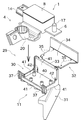
- FIG. 2 is an assembled perspective view of a battery sensor assembly.
- FIG. 2 is a perspective view of a battery sensor assembly.
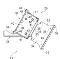
- the top view of a positioning tool The perspective view of a positioning tool.
- the perspective view which shows a mode that the conventional battery sensor was attached to the battery.
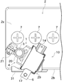
- FIG. 1 to 4 show a battery sensor assembly 10 according to an embodiment of the present invention.
- the battery sensor assembly 10 is attached to the battery post 3 of the battery 2.
- the surface of the battery 2 on which the battery post 3 is formed is referred to as an upper surface 2 a of the battery 2.
- the surface substantially orthogonal to the upper surface 2 a in the battery 2 is referred to as the side surface 2 b of the battery 2.
- the battery sensor assembly 10 is composed of a battery sensor 1 and a positioning tool 11.
- the battery sensor 1 of the present embodiment has a configuration equivalent to that of the conventional battery sensor 1 already described with reference to FIGS. 8 and 9. Therefore, in the following description of the present embodiment, the components already described may be assigned the same reference numerals as in FIGS. 8 and 9 and the description thereof may be omitted.
- the positioning tool 11 is made of synthetic resin, and the whole is integrally molded.
- the positioning tool 11 of the present embodiment is configured separately from the battery sensor 1.
- the configuration of the positioning tool 11 is shown in FIGS. 5 to 7.
- the positioning tool 11 includes a sensor fixing portion 29 and a rotation prevention portion 31.
- the sensor fixing portion 29 is configured to be able to fix the battery sensor 1 to the positioning tool 11.
- the battery sensor assembly 10 is configured by fixing the battery sensor 1 to the positioning tool 11.
- the battery post terminal 4 can be connected to the battery post 3 in a state where the battery sensor assembly 10 is configured (a state where the battery sensor 1 is fixed to the positioning tool 11).
- the harness 5 FIG. 1
- the harness connection portion 6 or connect a cable (not shown) for outputting a detection result to the connector 14 Can.
- the battery sensor assembly 10 is used by being attached to the battery 2 as it is (the battery sensor 1 is fixed to the positioning tool 11).
- the anti-rotation portion 31 is configured to contact the side surface 2 b of the battery 2. More specifically, in a state where the battery post 3 is inserted into the battery post connection portion 20 of the battery sensor assembly 10 (the state shown in FIGS. 1 and 2), the detent portion 31 contacts the side surface 2 b of the battery 2 .
- the battery sensor assembly 10 can be positioned with respect to the battery 2 by bringing the detent portion 31 into contact with the side surface 2 b of the battery 2. Therefore, the battery sensor assembly 10 can be prevented from rotating about the battery post 3.
- the present embodiment assumes the following cases. That is, an assembly worker fixes the battery sensor 1 to the positioning tool 11 at the assembly factory of the battery sensor assembly. Thus, the battery sensor assembly 10 is configured. The battery sensor assembly 10 configured in this way is carried into, for example, an automobile assembly plant. Then, in the automobile assembly plant, the installer attaches the battery post terminal 4 of the battery sensor assembly 10 to the battery post 3 of the battery 2 of the automobile.
- an installation worker may use an impact wrench or the like when tightening the tightening bolt 21 and the nut 18.
- an impact wrench or the like When an impact wrench or the like is used, the battery sensor assembly 10 tends to rotate around the battery post 3 due to the impact. If the battery sensor assembly 10 is rotated by the impact of the impact wrench, it is difficult to fix the battery sensor assembly 10 in a predetermined position.
- the battery sensor assembly 10 of the present embodiment assumes that the case 8 of the battery sensor 1 is disposed above the battery 2 as described in the item of “Problem to be Solved” (FIG. 2)). Therefore, temporarily, if the position where the battery sensor assembly 10 is attached deviates even a little from the state of FIG. 2, the battery sensor assembly 10 is covered on the battery liquid plug 7 and the liquid plug 7 is It can not be opened.
- the battery sensor assembly 10 since the battery sensor assembly 10 according to the present embodiment includes the detent portion 31 configured as described above, the battery post 3 is inserted into the battery post connection portion 20 to position it relative to the battery 2 Be done. Therefore, even if the impact of the impact wrench is applied, the battery sensor assembly 10 can be prevented from rotating around the battery post 3. Thus, the installer can attach the battery sensor assembly 10 to the battery 2 with high positional accuracy.
- the battery sensor assembly 10 can be reliably prevented from being covered by the battery liquid plug 7. Further, since the battery sensor assembly 10 can be accurately positioned, interference of the battery sensor assembly 10 with components (not shown) around the battery 2 can be reliably prevented.
- the sensor fixing portion 29 includes the fitting portion 30, the lid 32, the hinge 33, and the lock mechanism (the lock claw 36 and the lock 37).
- the fitting portion 30 is configured to be able to be fitted to the case 8 of the battery sensor 1.
- the case 8 of the battery sensor 1 of the present embodiment is formed in a substantially rectangular parallelepiped shape as shown in FIG.
- the fitting portion 30 is formed in a substantially square cylindrical shape so that at least a part of the rectangular parallelepiped case 8 can be inserted.
- the fitting portion 30 includes a substantially rectangular bottom surface 40 and side walls 41 vertically rising from four sides of the bottom surface 40.
- the bottom surface 40 and the four side walls 41 form a substantially square cylindrical fitting portion 30.
- the case 8 of the battery sensor 1 can be inserted into the fitting portion 30 from the direction orthogonal to the bottom surface 40 of the fitting portion 30 (the direction indicated by the arrow in FIG. 3) .
- the direction in which the case 8 is inserted into the fitting portion 30 may be simply referred to as the “insertion direction”.
- a plurality of ribs 42 are formed on each of the four side walls 41.
- Each rib 42 is formed on each side wall 41 so as to be convex toward the inside of the fitting portion 30, and is elongated along the insertion direction.
- Each rib 42 is configured to be in contact with the side surface of the case 8 inserted into the fitting portion 30.
- Each rib 42 has a portion in which the amount of protrusion from the side wall 41 increases as it proceeds in the insertion direction (as it approaches the bottom surface 40). That is, each rib 42 has a tapered portion.
- each rib 42 is formed in a tapered shape, when the case 8 is inserted into the fitting portion 30, the case 8 is guided by the taper and the case 8 is centered in the fitting portion 30. Ru. If the case 8 is further pressed in the insertion direction from that state, the tapered rib 42 bites into the outer surface of the case 8, and as a result, the case 8 is firmly fixed to the fitting portion 30. Thereby, rattling of case 8 in fitting part 30 can be prevented.
- the hinge part 33 has connected the fitting part 30 and the cover part 32.
- the hinge part 33 of this embodiment is a so-called thin hinge (living hinge). Therefore, the fitting portion 30 and the lid portion 32 are integrally connected by the hinge portion 33.
- the lid portion 32 can be pivoted with respect to the fitting portion 30 about the hinge portion 33.
- the lid 32 has a ceiling surface 34. By turning the lid 32 into the state shown in FIG. 4, the ceiling surface 34 of the lid 32 faces the bottom surface 40 of the fitting portion 30.
- the state of FIG. 4 is referred to as a state in which the lid 32 is “closed”.
- a plurality of bosses 35 are formed on the ceiling surface 34 of the lid 32.
- the boss 35 is formed as a substantially cylindrical small protrusion. Then, when the lid 32 is closed in a state where the case 8 is fitted to the fitting portion 30 (the state of FIG. 4), the boss 35 contacts the upper surface of the case 8 in the insertion direction It has become. Thus, the case 8 is pressed by the boss 35 toward the bottom surface 40 of the fitting portion 30.
- the aforementioned lock mechanism is composed of the lock claw 36 and the lock portion 37.
- the lock claws 36 are formed on the lid 32.
- the lock portion 37 is formed in the fitting portion 30.
- the assembly worker inserts the case 8 of the battery sensor 1 into the fitting portion 30 of the positioning tool 11 and fits it (FIG. 3), and closes the lid 32 to lock it.
- the battery sensor 1 can be fixed to the positioning tool 11 simply by engaging the mechanism (the lock claw 36 and the lock portion 37) (FIG. 4).
- the battery sensor 1 can be easily fixed to the positioning tool 11.
- the positioning tool 11 of this embodiment positions the case 8 of the battery sensor 1 in a state of being disposed above the battery 2. Therefore, when the battery sensor assembly 10 is attached to the battery 2, the positioning tool 11 of the present embodiment is configured such that the sensor fixing portion 29 is located above the battery 2. More specifically, when the battery sensor assembly 10 is attached to the battery 2, at least a part of the bottom surface 40 of the fitting portion 30 is disposed to cover the top surface 2 a of the battery 2. As shown in FIG. 7, in the present embodiment, the bottom surface 40 of the fitting portion 30 is disposed so as to be substantially parallel to the top surface 2 a of the battery 2. Thus, the case 8 of the battery sensor 1 can be positioned in a state of being disposed above the battery 2.
- the detent portion 31 is configured to contact the side surface 2 b of the battery 2 in a state where the battery post 3 is inserted into the battery post connection portion 20 (state shown in FIGS. 1 and 2) . This can prevent the battery sensor assembly 10 from rotating about the battery post 3.
- the rotation prevention part 31 of this embodiment is comprised so that the side surface 2b of the battery 2 may be contacted in a wide range so that the said impact can be disperse
- the detent 31 is formed in a wide plate shape, and the width W (shown in FIG. 1) is wider than the lateral width of the case 8 of the battery sensor 1 It has become.
- the detent portion 31 is configured to contact the side surface 2 b of the battery 2 over the entire width W thereof.
- the detent portion 31 of the present embodiment forms the width W of the portion in contact with the side surface 2 b of the battery 2 wide, an impact wrench or the like is used when tightening the tightening bolt 21 and the nut 18.
- the impact applied to the anti-rotation portion 31 can be dispersed at the same time. Thereby, the impact can be prevented from concentrating on a specific place, and the positioning tool 11 can be prevented from being deformed or broken.
- each reinforcing rib 46 is formed to be convex toward the side surface 2 b of the battery 2. Further, as shown in FIG. 7, each reinforcing rib 46 is elongated along the direction orthogonal to the bottom surface 40 of the fitting portion 30. Further, as shown in FIG. 6, the plurality of reinforcing ribs 46 are formed side by side in the direction (the width direction of the rotation prevention portion 31) orthogonal to the longitudinal direction.
- the detent portion 31 is reinforced by the reinforcing rib 46, the deformation of the detent portion 31 can be prevented. Therefore, even if an impact wrench or the like is used at the time of mounting, deformation of the detent portion 31 can be suppressed, so that the battery sensor assembly 10 can be attached to the battery 2 with high accuracy.
- each reinforcing rib 46 is formed such that its longitudinal direction is parallel to the bottom surface 40 of the fitting portion 30 by changing its longitudinal direction at its upper end portion. .
- This portion is called the horizontal portion 46 a of the reinforcing rib 46.
- the reinforcing rib 46 is formed in a substantially L shape.
- the horizontal portion 46 a of the reinforcing rib 46 is connected to the bottom surface 40 of the fitting portion 30.
- the reinforcing rib 46 of the present embodiment is configured in an L shape so as to connect the bottom surface 40 of the fitting portion 30 and the rotation preventing portion 31. Therefore, the reinforcing rib 46 has a function of reinforcing so as to maintain the angle formed by the detent portion 31 and the bottom surface 40 of the fitting portion 30. Thereby, even if a large impact is applied to the detent 31 by use of an impact wrench or the like, it is possible to prevent a deformation in which the angle formed by the detent 31 and the bottom surface 40 of the fitting 30 is widened.
- the reinforcing rib 46 formed in the detent portion 31 is formed to protrude toward the side surface 2 b of the battery 2. Therefore, the detent portion 31 of the present embodiment is in contact with the side surface 2 b of the battery 2 by the reinforcing rib 46.
- the detent portion 31 of the present embodiment is formed to have a large width W, it is difficult to form the detent portion 31 smoothly and precisely over the entire width. Similarly, there is no guarantee that the side 2b of the battery 2 is a perfect smooth surface. Therefore, even if it is difficult to bring the anti-rotation portion 31 and the side surface 2b of the battery 2 into close contact with each other, it is difficult for the battery sensor assembly 10 to rattle, and as a result, sufficient. Positioning accuracy can not be obtained. Therefore, as described above, the detent portion 31 is brought into contact with the side surface 2 b of the battery 2 by the reinforcing rib 46.
- the battery sensor assembly 10 can be prevented from rattling even if the side surface 2 b is not a perfectly smooth surface. Thereby, the positioning accuracy of the battery sensor assembly 10 can be improved.
- the positioning tool 11 of the present embodiment includes the sensor fixing portion 29 for fixing the battery sensor 1 and the detent portion 31 capable of contacting the side surface 2 b of the battery 2.
- the positioning tool 11 can be prevented from rotating around the battery post 3. Therefore, by fixing the battery sensor 1 to the positioning tool 11, the battery sensor 1 can be prevented from rotating about the battery post 3, so the battery sensor 1 can be positioned with respect to the battery 2 with high accuracy.
- the sensor fixing portion 29 of the positioning tool 11 of the present embodiment includes the fitting portion 30.
- the fitting portion 30 is capable of inserting the case 8 of the battery sensor 1 in a predetermined insertion direction, and fits with the inserted battery sensor 1.
- the fitting portion 30 contacts the battery sensor 1 by the plurality of tapered ribs 42 formed along the insertion direction.
- the fitting portion 30 is configured to contact the battery sensor 1 with the rib 42, it is possible to suppress rattling of the battery sensor 1 fitted to the fitting portion 30. Furthermore, since the rib 42 is tapered, the rib 42 can be bitten into the battery sensor 1 by pressing the battery sensor 1 into the fitting portion 30, and the battery sensor 1 can be firmly fixed.
- the sensor fixing portion 29 of the present embodiment further includes the lid 32 that contacts the battery sensor 1 fitted in the fitting portion 30 in the insertion direction.
- the battery sensor 1 can be prevented from coming off from the fitting portion 30 by providing the lid portion 32 in this manner, the battery sensor 1 can be reliably fixed to the positioning tool 11.
- the lid 32 of the present embodiment contacts the battery sensor 1 by the plurality of bosses 35.
- the lid 32 is configured to be in contact with the battery sensor 1 by the plurality of bosses 35, thereby suppressing rattling of the battery sensor 1 when the lid 32 is in contact with the battery sensor 1 be able to.
- the sensor fixing portion 29 of the present embodiment includes the hinge portion 33 and the lock mechanism.
- the hinge portion 33 integrally connects the lid portion 32 to the fitting portion 30.
- the lock mechanism locks the lid 32 in a state in which the lid 32 is in contact with the battery sensor 1 (in a state where the lid 32 is closed).
- both can be formed by integral molding.
- the battery sensor 1 can be reliably fixed by rotating the lid 32 and locking with the lock, the battery sensor 1 can be easily fixed to the positioning tool 11. .
- the detent portion 31 of the present embodiment includes the reinforcing rib 46.
- the reinforcing rib 46 can contact the side surface 2 b of the battery 2.
- the battery sensor assembly 10 of the present embodiment includes the positioning tool 11 described above and the battery sensor 1 fixed to the sensor fixing portion 29 of the positioning tool 11.
- the battery sensor assembly 10 is provided with the detent portion 31, it can be attached to the battery 2 with high accuracy.
- the battery sensor assembly 10 of the above embodiment the battery sensor 1 and the positioning tool 11 are separated. According to this structure, the effects of the present invention can be obtained only by attaching the positioning tool 11 of the present invention to the conventional battery sensor 1. That is, the above embodiment has an advantage that the conventional battery sensor 1 can be used as it is.
- the battery sensor 1 and the positioning tool 11 do not necessarily have to be separately configured.
- the structure which integrated the battery sensor 1 and the positioning tool 11 can be considered.
- fixed part 29 of the said embodiment is unnecessary. Therefore, this alternative embodiment may be considered as a configuration in which the rotation preventing portion 31 is directly provided to the battery sensor 1 by omitting the sensor fixing portion 29 of the above embodiment.
- the sensor fixing portion 29 may have a configuration that can appropriately fix the battery sensor 1. Therefore, the sensor fixing unit 29 is not limited to the configuration described in the above embodiment, and various modifications can be considered.
- fitting to the fitting portion 30 is not limited to the case 8.
- the other portion of the battery sensor 1 and the fitting portion 30 may be fitted together.
- the lid 32 can be omitted.
- fixed part 29 may be the structure which fixes the battery sensor 1 by methods other than fitting.
- the positioning tool 11 of the above embodiment assumes that the case 8 of the battery sensor 1 is positioned above the battery 2.
- the position at which the battery sensor 1 is positioned by the positioning tool 11 of the present invention is not limited to the above embodiment.
- the positioning tool 11 can be configured to position the case 8 of the battery sensor 1 by projecting it to the side of the battery 2.
- the structure of the positioning tool 11 is not limited to the structure demonstrated by the said embodiment, It can change suitably. The same applies to the battery sensor 1.
Landscapes
- Chemical & Material Sciences (AREA)
- Chemical Kinetics & Catalysis (AREA)
- Electrochemistry (AREA)
- General Chemical & Material Sciences (AREA)
- Physics & Mathematics (AREA)
- General Physics & Mathematics (AREA)
- Engineering & Computer Science (AREA)
- Manufacturing & Machinery (AREA)
- Battery Mounting, Suspending (AREA)
- Secondary Cells (AREA)
- Connection Of Batteries Or Terminals (AREA)
Abstract
Description
2 バッテリー
2a バッテリーの側面
3 バッテリーポスト
10 バッテリーセンサアッセンブリ
11 位置決め具
29 センサ固定部
30 嵌合部
31 回り止め部
32 蓋部
Claims (10)
- バッテリーのバッテリーポストに取り付けられるバッテリーセンサを位置決めするための位置決め具であって、
前記バッテリーセンサを固定するセンサ固定部と、
前記バッテリーの側面に接触可能な回り止め部と、
を備えることを特徴とする位置決め具。 - 請求項1に記載の位置決め具であって、
前記センサ固定部は、前記バッテリーセンサの少なくとも一部を所定の挿入方向から挿入可能であり、当該挿入されたバッテリーセンサに嵌合する嵌合部を備えることを特徴とする位置決め具。 - 請求項2に記載の位置決め具であって、
前記嵌合部は、前記挿入方向に沿って形成された複数のテーパ状リブにより、前記バッテリーセンサに対して接触することを特徴とする位置決め具。 - 請求項2に記載の位置決め具であって、
前記センサ固定部は、前記嵌合部に嵌合した前記バッテリーセンサに対して、前記挿入方向から接触する蓋部を更に備えることを特徴とする位置決め具。 - 請求項4に記載の位置決め具であって、
前記蓋部は、複数のボスにより前記バッテリーセンサに接触することを特徴とする位置決め具。 - 請求項4に記載の位置決め具であって、
前記センサ固定部は、
前記嵌合部に対して前記蓋部を一体的に接続するヒンジ部と、
前記蓋部を、前記バッテリーセンサに接触した状態でロックするためのロック機構と、
を備えることを特徴とする位置決め具。 - 請求項1に記載の位置決め具であって、
前記回り止め部は、補強リブを備えていることを特徴とする位置決め具。 - 請求項7に記載の位置決め具であって、
前記補強リブが前記バッテリーの側面に接触可能であることを特徴とする位置決め具。 - 請求項1に記載の位置決め具と、
当該位置決め具の前記センサ固定部に固定されたバッテリーセンサと、
を備えることを特徴とするバッテリーセンサアッセンブリ。 - バッテリーのバッテリーポストに取り付けられるバッテリーセンサであって、
前記バッテリーの側面に接触可能な回り止め部を備えることを特徴とするバッテリーセンサ。
Priority Applications (3)
| Application Number | Priority Date | Filing Date | Title |
|---|---|---|---|
| JP2015522505A JP6089105B2 (ja) | 2013-06-11 | 2014-05-28 | バッテリーセンサの位置決め具、これを備えるバッテリーセンサアッセンブリ、及びバッテリーセンサ |
| CN201480033086.6A CN105308788B (zh) | 2013-06-11 | 2014-05-28 | 电池传感器的定位工具、具备该定位工具的电池传感器组件和电池传感器 |
| US14/965,827 US10218038B2 (en) | 2013-06-11 | 2015-12-10 | Battery sensor positioner, battery sensor assembly equipped with same, and battery sensor |
Applications Claiming Priority (2)
| Application Number | Priority Date | Filing Date | Title |
|---|---|---|---|
| JP2013122869 | 2013-06-11 | ||
| JP2013-122869 | 2013-06-11 |
Related Child Applications (1)
| Application Number | Title | Priority Date | Filing Date |
|---|---|---|---|
| US14/965,827 Continuation US10218038B2 (en) | 2013-06-11 | 2015-12-10 | Battery sensor positioner, battery sensor assembly equipped with same, and battery sensor |
Publications (1)
| Publication Number | Publication Date |
|---|---|
| WO2014199576A1 true WO2014199576A1 (ja) | 2014-12-18 |
Family
ID=52021897
Family Applications (1)
| Application Number | Title | Priority Date | Filing Date |
|---|---|---|---|
| PCT/JP2014/002809 Ceased WO2014199576A1 (ja) | 2013-06-11 | 2014-05-28 | バッテリーセンサの位置決め具、これを備えるバッテリーセンサアッセンブリ、及びバッテリーセンサ |
Country Status (4)
| Country | Link |
|---|---|
| US (1) | US10218038B2 (ja) |
| JP (1) | JP6089105B2 (ja) |
| CN (1) | CN105308788B (ja) |
| WO (1) | WO2014199576A1 (ja) |
Cited By (4)
| Publication number | Priority date | Publication date | Assignee | Title |
|---|---|---|---|---|
| WO2020209237A1 (ja) * | 2019-04-09 | 2020-10-15 | 古河電気工業株式会社 | バッテリー状態検知装置 |
| JP2020173917A (ja) * | 2019-04-09 | 2020-10-22 | 古河電気工業株式会社 | バッテリー状態検知装置 |
| JP2020173174A (ja) * | 2019-04-11 | 2020-10-22 | 古河電気工業株式会社 | バッテリー状態検知装置 |
| JP2024161651A (ja) * | 2023-05-08 | 2024-11-20 | 矢崎総業株式会社 | バッテリーターミナルカバー及びバッテリーターミナルユニット |
Families Citing this family (4)
| Publication number | Priority date | Publication date | Assignee | Title |
|---|---|---|---|---|
| US10527464B2 (en) * | 2016-08-18 | 2020-01-07 | Ford Global Technologies, Llc | Rotatable sensor cover |
| CN108761144A (zh) * | 2018-05-26 | 2018-11-06 | 史里司 | 一种可拆卸滑轨式电池传感器固定装置 |
| CN110858672B (zh) * | 2018-08-23 | 2023-02-21 | 本田技研工业株式会社 | 电池模块 |
| CN111999427B (zh) * | 2020-07-07 | 2022-06-28 | 安徽华能电缆集团有限公司 | 一种高阻燃无卤低烟低毒电力电缆的检测装置 |
Citations (3)
| Publication number | Priority date | Publication date | Assignee | Title |
|---|---|---|---|---|
| JP2010160990A (ja) * | 2009-01-09 | 2010-07-22 | Yazaki Corp | バッテリーターミナル用樹脂部品、及び、樹脂部品付きバッテリーターミナル |
| JP2011175884A (ja) * | 2010-02-25 | 2011-09-08 | Yazaki Corp | 電流センサ付きバッテリーターミナル |
| JP2011181191A (ja) * | 2010-02-26 | 2011-09-15 | Yazaki Corp | 電流センサ付きバッテリーターミナル |
Family Cites Families (14)
| Publication number | Priority date | Publication date | Assignee | Title |
|---|---|---|---|---|
| US6034614A (en) * | 1997-02-13 | 2000-03-07 | Haley; Chester M. | Seismically activated apparatus |
| EP1156552B1 (en) * | 2000-03-07 | 2006-06-21 | Sumitomo Wiring Systems, Ltd. | A construction for preventing erroneous assembling of battery terminals, a battery and a set of terminals |
| JP3697154B2 (ja) * | 2000-11-01 | 2005-09-21 | 住友電装株式会社 | 電流センサ付きバッテリターミナル |
| JP4421128B2 (ja) * | 2001-03-19 | 2010-02-24 | ジェコー株式会社 | 電流センサの取り付け構造 |
| DE102006046137B4 (de) | 2006-09-28 | 2019-02-14 | Continental Automotive Gmbh | Batteriesensoreinheit |
| JP5371297B2 (ja) * | 2008-07-04 | 2013-12-18 | 矢崎総業株式会社 | バッテリーターミナル |
| EP2159882B1 (en) * | 2008-08-29 | 2016-12-28 | Sumitomo Wiring Systems, Ltd. | A battery terminal unit and method of mounting it |
| JP2011181297A (ja) * | 2010-03-01 | 2011-09-15 | Yazaki Corp | 電流センサ付きバッテリーターミナル |
| JP5582844B2 (ja) * | 2010-03-30 | 2014-09-03 | 古河電気工業株式会社 | バッテリー状態検知センサ |
| JP5938778B2 (ja) | 2010-11-17 | 2016-06-22 | 矢崎総業株式会社 | 電流センサ付きバッテリーターミナル |
| WO2012067251A1 (en) | 2010-11-17 | 2012-05-24 | Yazaki Corporation | Battery terminal with current sensor |
| JP5809793B2 (ja) | 2010-11-17 | 2015-11-11 | 矢崎総業株式会社 | 電流センサ付きバッテリーターミナル |
| JP5541268B2 (ja) * | 2011-11-29 | 2014-07-09 | 横河電機株式会社 | 電池収納装置 |
| JP5794636B2 (ja) * | 2012-02-20 | 2015-10-14 | 本田技研工業株式会社 | 電動車両用電源装置の端子台 |
-
2014
- 2014-05-28 WO PCT/JP2014/002809 patent/WO2014199576A1/ja not_active Ceased
- 2014-05-28 CN CN201480033086.6A patent/CN105308788B/zh active Active
- 2014-05-28 JP JP2015522505A patent/JP6089105B2/ja active Active
-
2015
- 2015-12-10 US US14/965,827 patent/US10218038B2/en active Active
Patent Citations (3)
| Publication number | Priority date | Publication date | Assignee | Title |
|---|---|---|---|---|
| JP2010160990A (ja) * | 2009-01-09 | 2010-07-22 | Yazaki Corp | バッテリーターミナル用樹脂部品、及び、樹脂部品付きバッテリーターミナル |
| JP2011175884A (ja) * | 2010-02-25 | 2011-09-08 | Yazaki Corp | 電流センサ付きバッテリーターミナル |
| JP2011181191A (ja) * | 2010-02-26 | 2011-09-15 | Yazaki Corp | 電流センサ付きバッテリーターミナル |
Cited By (8)
| Publication number | Priority date | Publication date | Assignee | Title |
|---|---|---|---|---|
| WO2020209237A1 (ja) * | 2019-04-09 | 2020-10-15 | 古河電気工業株式会社 | バッテリー状態検知装置 |
| JP2020173917A (ja) * | 2019-04-09 | 2020-10-22 | 古河電気工業株式会社 | バッテリー状態検知装置 |
| JP7112983B2 (ja) | 2019-04-09 | 2022-08-04 | 古河電気工業株式会社 | バッテリー状態検知装置 |
| US11971453B2 (en) | 2019-04-09 | 2024-04-30 | Furukawa Electric Co., Ltd. | Battery state detection device |
| JP2020173174A (ja) * | 2019-04-11 | 2020-10-22 | 古河電気工業株式会社 | バッテリー状態検知装置 |
| JP7112984B2 (ja) | 2019-04-11 | 2022-08-04 | 古河電気工業株式会社 | バッテリー状態検知装置 |
| JP2024161651A (ja) * | 2023-05-08 | 2024-11-20 | 矢崎総業株式会社 | バッテリーターミナルカバー及びバッテリーターミナルユニット |
| JP7849329B2 (ja) | 2023-05-08 | 2026-04-21 | 矢崎総業株式会社 | バッテリーターミナルカバーを備える装置 |
Also Published As
| Publication number | Publication date |
|---|---|
| CN105308788B (zh) | 2018-01-02 |
| JPWO2014199576A1 (ja) | 2017-02-23 |
| US20160099487A1 (en) | 2016-04-07 |
| JP6089105B2 (ja) | 2017-03-01 |
| CN105308788A (zh) | 2016-02-03 |
| US10218038B2 (en) | 2019-02-26 |
Similar Documents
| Publication | Publication Date | Title |
|---|---|---|
| WO2014199576A1 (ja) | バッテリーセンサの位置決め具、これを備えるバッテリーセンサアッセンブリ、及びバッテリーセンサ | |
| US7815443B2 (en) | Electrical connection box and method of assembling the electrical connection box | |
| US20080149387A1 (en) | Electrical junction box | |
| US9742170B2 (en) | Electrical junction box and wire harness | |
| JP5422306B2 (ja) | 車両用ルーフマウントアンテナ装置 | |
| CN108352651B (zh) | 密封盖 | |
| US9694763B2 (en) | Wire harness protector having grounding function | |
| JP2010287386A (ja) | 電流センサ付きバッテリーターミナル | |
| US20160372847A1 (en) | Battery terminal stopper and battery terminal unit | |
| US20140043193A1 (en) | Star-handle system for locking antenna to a vehicle roof | |
| JP5151939B2 (ja) | 電気接続箱 | |
| JP2020031517A (ja) | 電気接続箱 | |
| JP6238874B2 (ja) | 電気接続箱 | |
| US20240388015A1 (en) | Wire harness and protector | |
| JP2003317823A (ja) | 端子保護キャップ | |
| WO2017068807A1 (ja) | 車両バックドア用ラッチ装置 | |
| JP6677991B2 (ja) | バッテリー端子ストッパ、及び、バッテリー端子ユニット | |
| JP5030223B2 (ja) | プロテクタ | |
| JP5211937B2 (ja) | バッテリ端子ユニット及びバッテリ端子の取付構造 | |
| JP6904988B2 (ja) | 電気接続箱 | |
| JP5641353B2 (ja) | シールドコネクタの取付構造 | |
| JP5056639B2 (ja) | コネクタ | |
| KR102869794B1 (ko) | 차량용 정션블록 | |
| JP2018207711A (ja) | 電気接続箱 | |
| KR20140083827A (ko) | 자동차용 박스의 단자연결장치 |
Legal Events
| Date | Code | Title | Description |
|---|---|---|---|
| WWE | Wipo information: entry into national phase |
Ref document number: 201480033086.6 Country of ref document: CN |
|
| 121 | Ep: the epo has been informed by wipo that ep was designated in this application |
Ref document number: 14811362 Country of ref document: EP Kind code of ref document: A1 |
|
| ENP | Entry into the national phase |
Ref document number: 2015522505 Country of ref document: JP Kind code of ref document: A |
|
| NENP | Non-entry into the national phase |
Ref country code: DE |
|
| 122 | Ep: pct application non-entry in european phase |
Ref document number: 14811362 Country of ref document: EP Kind code of ref document: A1 |