EP1156552B1 - A construction for preventing erroneous assembling of battery terminals, a battery and a set of terminals - Google Patents
A construction for preventing erroneous assembling of battery terminals, a battery and a set of terminals Download PDFInfo
- Publication number
- EP1156552B1 EP1156552B1 EP01105306A EP01105306A EP1156552B1 EP 1156552 B1 EP1156552 B1 EP 1156552B1 EP 01105306 A EP01105306 A EP 01105306A EP 01105306 A EP01105306 A EP 01105306A EP 1156552 B1 EP1156552 B1 EP 1156552B1
- Authority
- EP
- European Patent Office
- Prior art keywords
- terminals
- terminal
- battery
- electrode
- electrode portions
- Prior art date
- Legal status (The legal status is an assumption and is not a legal conclusion. Google has not performed a legal analysis and makes no representation as to the accuracy of the status listed.)
- Expired - Lifetime
Links
- 238000010276 construction Methods 0.000 title claims description 22
- 230000004308 accommodation Effects 0.000 claims description 4
- 230000000052 comparative effect Effects 0.000 description 39
- 230000037431 insertion Effects 0.000 description 22
- 238000003780 insertion Methods 0.000 description 22
- 239000004020 conductor Substances 0.000 description 5
- 210000000078 claw Anatomy 0.000 description 4
- 238000002788 crimping Methods 0.000 description 2
- 230000000694 effects Effects 0.000 description 2
- 239000011810 insulating material Substances 0.000 description 2
- 239000007769 metal material Substances 0.000 description 2
- 230000001419 dependent effect Effects 0.000 description 1
- 230000009977 dual effect Effects 0.000 description 1
- 230000002401 inhibitory effect Effects 0.000 description 1
- 230000002452 interceptive effect Effects 0.000 description 1
- 239000002184 metal Substances 0.000 description 1
- 229920003002 synthetic resin Polymers 0.000 description 1
- 239000000057 synthetic resin Substances 0.000 description 1
- 238000003466 welding Methods 0.000 description 1
Images


Classifications
-
- H—ELECTRICITY
- H01—ELECTRIC ELEMENTS
- H01R—ELECTRICALLY-CONDUCTIVE CONNECTIONS; STRUCTURAL ASSOCIATIONS OF A PLURALITY OF MUTUALLY-INSULATED ELECTRICAL CONNECTING ELEMENTS; COUPLING DEVICES; CURRENT COLLECTORS
- H01R11/00—Individual connecting elements providing two or more spaced connecting locations for conductive members which are, or may be, thereby interconnected, e.g. end pieces for wires or cables supported by the wire or cable and having means for facilitating electrical connection to some other wire, terminal, or conductive member, blocks of binding posts
- H01R11/11—End pieces or tapping pieces for wires, supported by the wire and for facilitating electrical connection to some other wire, terminal or conductive member
- H01R11/28—End pieces consisting of a ferrule or sleeve
- H01R11/281—End pieces consisting of a ferrule or sleeve for connections to batteries
- H01R11/282—End pieces consisting of a ferrule or sleeve for connections to batteries comprising means for facilitating engagement or disengagement, e.g. quick release terminal
-
- H—ELECTRICITY
- H01—ELECTRIC ELEMENTS
- H01R—ELECTRICALLY-CONDUCTIVE CONNECTIONS; STRUCTURAL ASSOCIATIONS OF A PLURALITY OF MUTUALLY-INSULATED ELECTRICAL CONNECTING ELEMENTS; COUPLING DEVICES; CURRENT COLLECTORS
- H01R11/00—Individual connecting elements providing two or more spaced connecting locations for conductive members which are, or may be, thereby interconnected, e.g. end pieces for wires or cables supported by the wire or cable and having means for facilitating electrical connection to some other wire, terminal, or conductive member, blocks of binding posts
- H01R11/11—End pieces or tapping pieces for wires, supported by the wire and for facilitating electrical connection to some other wire, terminal or conductive member
- H01R11/28—End pieces consisting of a ferrule or sleeve
- H01R11/281—End pieces consisting of a ferrule or sleeve for connections to batteries
- H01R11/283—Bolt, screw or threaded ferrule parallel to the battery post
-
- H—ELECTRICITY
- H01—ELECTRIC ELEMENTS
- H01R—ELECTRICALLY-CONDUCTIVE CONNECTIONS; STRUCTURAL ASSOCIATIONS OF A PLURALITY OF MUTUALLY-INSULATED ELECTRICAL CONNECTING ELEMENTS; COUPLING DEVICES; CURRENT COLLECTORS
- H01R11/00—Individual connecting elements providing two or more spaced connecting locations for conductive members which are, or may be, thereby interconnected, e.g. end pieces for wires or cables supported by the wire or cable and having means for facilitating electrical connection to some other wire, terminal, or conductive member, blocks of binding posts
- H01R11/11—End pieces or tapping pieces for wires, supported by the wire and for facilitating electrical connection to some other wire, terminal or conductive member
- H01R11/28—End pieces consisting of a ferrule or sleeve
- H01R11/281—End pieces consisting of a ferrule or sleeve for connections to batteries
- H01R11/289—End pieces consisting of a ferrule or sleeve for connections to batteries characterised by the shape or the structure of the battery post
-
- H—ELECTRICITY
- H01—ELECTRIC ELEMENTS
- H01R—ELECTRICALLY-CONDUCTIVE CONNECTIONS; STRUCTURAL ASSOCIATIONS OF A PLURALITY OF MUTUALLY-INSULATED ELECTRICAL CONNECTING ELEMENTS; COUPLING DEVICES; CURRENT COLLECTORS
- H01R13/00—Details of coupling devices of the kinds covered by groups H01R12/70 or H01R24/00 - H01R33/00
- H01R13/64—Means for preventing incorrect coupling
- H01R13/642—Means for preventing incorrect coupling by position or shape of contact members
Definitions
- the present invention relates to a construction for preventing erroneous assembling of battery terminals, to a battery and to a set of terminals for the connection therewith.
- shafts project as a (+)-electrode and a (-)-electrode from the upper surface of an automotive battery, and these shafts are connected with each other by being inserted into round holes of terminals connected with a battery cord and fastening the terminals thereto with nuts or the like.
- the battery terminals are connectable with either one of the electrodes due to their constructions, they may be connected with incorrect electrodes.
- both the two terminals and the two electrode portions comprise identification means for enabling assembling only in the case of a correct correspondence of the terminals and the electrode portions while making it impossible to assemble the terminals with the electrode portions in the case of an incorrect correspondence.
- the identification means enables assembling of the terminals and the electrode portions in the case of the correct correspondence while making it impossible to assemble the terminals with the electrode portions not corresponding thereto.
- the battery can be easily distinguished in appearance from those of existing standards if it has new standards.
- the identification means of the electrode portions comprises a threaded shaft provided in one electrode portion and a nut provided in the other electrode portion
- the identification means of the terminals comprises a nut which is provided in the terminal corresponding to the one electrode portion having the threaded shaft and can be screwed down on the threaded shaft, and a threaded shaft which is provided in the terminal corresponding to the other electrode portion having the nut and is engageable with the nut of the other electrode portion.
- the identification means of the terminals comprises a cover which is provided separately from the terminal and is to be mounted or mountable on or over the terminal.
- connection of the terminals and the electrode portions not corresponding to each other is prohibited by the identification means.
- the identification means of the electrode portions comprises a terminal accommodating portion for enabling accommodation of the terminal provided with the cover by confirming or corresponding to the cover in the case of a correct correspondence between the terminals and the electrode portions while making it impossible to connect the terminals with the electrode portions by causing the cover to interfere the battery, preferably an upper surface of the battery in the case of an incorrect correspondence.
- the construction further comprises rotation preventing means for preventing rotation of the terminals with respect to the corresponding electrode portions by mutual engagement.
- FIGS. 1 to 3 show a first comparative example
- FIG. 1 shows a portion of an inventive battery B near its electrode portions, and the battery B used here is e.g. a 36V-battery (usually 12V-battery).
- the left and right corners of the battery B are recessed to form recessed or electrode or engaging portions 10a, 10b, and a (+)-electrode portion 11a and a (-)-electrode portion 11b are provided on the first or bottom surfaces of the engaging portions 10a, 10b.
- Both electrode portions 10a, 10b are constructed such that threaded shafts 13a, 13b vertically or substantially normally project substantially in the middle of washers 12 preferably in the form of a square flat plate as shown in FIG. 1.
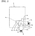
- first and second recesses 14a, 14b, 23a, 23b are formed in two side or lateral walls of the respective engaging portions 10a, 10b, and the corresponding recesses 14a, 23a and 14b, 23b of the engaging portions 10a, 10b are transversely symmetrically formed or formed such that the recessing directions of the corresponding recesses 14a, 23a and 14b, 23b are arranged at an angle different from 0° or 180°, preferably substantially normal with respect to each other (FIG. 2), wherein the recesses 14a and 14b as well as 23a and 23b are preferably substantially symmetrical with respect to a line L transversely extending between the electrodes 11a. 11 b.
- terminals 15a, 15b to be connected with the electrode portions 11 a, 11 b are made of a conductive metallic material and each have a barrel portion 16 at its rear end for connection of a battery cord or conductor C preferably by crimping.
- Front portions of the terminal 15a, 15b are base plates 17 which are bent at an angle different from 0° or 180°, preferably substantially at a right angle to the barrel portions 16, and are each formed in its middle with an insertion hole 18 into or through which the threaded shaft 13a, 13b is insertable or fittable.
- the base plates 17 of the left and right terminals 15a, 15b are so formed as to be transversely symmetrical or with respect to the line L when fitted on the battery B.
- identification pieces 19a, 19b project forward from the leading end of the base plates 17 of the respective terminals 15a, 15b.
- the identification pieces 19a, 19b have substantially half the width of the leading edge of the base plates 17, and are selectively fittable or insertable into the first or second recesses 14a, 14b, 23a, 23b (see FIG. 2).
- the identification pieces 19a, 19b of the left and right terminals 15a, 15b are also so formed as to be transversely symmetrical or with respect to the line L when fitted on the battery B.
- the identification pieces 19a, 19b interfere the upper surface of the battery B to prevent the terminals 15a, 15b from being assembled with the electrode portions 11a, 11b. If a correspondence between the terminals 15a, 15b and the electrode portions 11 a, 11 b is correct, the identification pieces 19a, 19b are fitted into the first or second recesses 14a, 14b, 23a, 23b, enabling connection of the terminals 15a, 15b with the electrode portions 11 a, 11 b. In other words, an identification means is constructed by the identification pieces 19a, 19b and the recesses 14a, 14b, 23a, 23b.
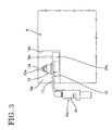
- the washers 12 are or can be tightly held by or interact with the first and second rotation preventing pieces 20a, 20b, 21 a, 21 b, with the result that the rotation of the terminals 15a, 15b when nuts 22 are screwed down on the threaded shafts 13a, 13b can be prevented.
- the first comparative example is constructed as described above. If the correspondence between the terminals 15a, 15b and the electrode portions 11 a, 11 b is correct, the identification pieces 19a, 19b are fitted or fittable into the first or second recesses 14a, 14b, 23a, 23b. Then, the washers 12 are tightly held by or interact with the first and second rotation preventing pieces 20a, 20b, 21 a, 21 b while the threaded shafts 13a, 13b are inserted into the insertion holes 18.
- the terminals 15a, 15b can be assembled with the rotation of the terminals 15a, 15b prevented by the rotation preventing pieces 20a, 20b, 21a, 21b. In this way, connection of the terminals 15a, 15b with the correctly corresponding electrode portions 11 a, 11 b is completed.
- the identification pieces 19a, 19b are fitted into neither the first nor second recesses 14a, 14b, 23a, 23b and interfere the upper surface of the battery B, with the result that the terminals 15a, 15b cannot be assembled with the engaging portions 10a, 10b.
- an operator can immediately notice an incorrect arrangement of the terminals 15a, 15b.
- the battery B according to this embodiment has a special form in which the engaging portions 10a, 10b are formed around the electrode portions 11a, 11 b, it contributes to distinction from conventional 12V-batteries. Furthermore, since the depth of the engaging portions 10a, 10b is set such that the threaded shafts 13a, 13b do not project to the upper surface of the battery B, there is also an effect of avoiding an inadvertent contact of a tool or the like with the threaded shafts.
- FIGS. 4 and 5 show a preferred embodiment of the invention.
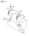
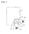
- one (left one in FIG. 4) of electrode portions 31a, 31 b has a threaded shaft 33b similar to the first embodiment, whereas the other is such that a nut 33a is embedded in a washer 32.
- Around the electrode portions 31a, 31b are formed substantially rectangular recesses 30a, 30b without having the recesses 14a, 14b, 23a, 23b of the first embodiment. Accordingly, each terminal 35a, 35b is not formed with an identification piece, but is formed with a pair of rotation preventing pieces 36a, 36b or 37a, 37b for tightly holding the washers 32.
- a bolt (threaded shaft) 34 is made integral or unitary to one terminal 35a (right one in FIG. 4) preferably by a temporary locking mechanism not shown in detail while having its rotation permitted.
- the temporary locking mechanism may be such that the lower surface of a head of the bolt 34 and a base plate of the terminal 35a is slightly connected by, e.g. welding and this welded part is broken as the bolt 34 is screwed or may be such that a claw for softly engaging a thread of the bolt is formed at the edge of the insertion hole.
- the bolt 34 may be formed with a recess which engages the base plate of the terminal 35a so as to allow for a further rotation of the bolt 34 while longitudinally or axially positioning or holding it with respect to the base plate.
- the terminal 35b can be fastened to the electrode portion 31 b having the threaded shaft 33a with a nut 39, whereas the terminal 35 can be fastened to the electrode portion 31 having the embedded nut 33b by screwing the bolt 34 thereof into the nut 33b.
- the nut may be similarly temporarily coupled.
- the other construction is the same or similar as in the first comparative example and, accordingly, the same function and result can be obtained.
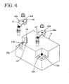
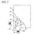
- FIGS. 6 and 7 shows a second comparative example Electrode portions 41a, 41 b in this comparative example have threaded shafts 43a, 43b having smaller and larger diameters. Engaging portions are recessed in depth direction similar to the foregoing first comparative example and embodiment, and two side walls of the left engaging portion in FIG. 6 are recessed to form first and second key receiving portions 48, 49 having an identical shape.
- Insertion holes 48a, 48b piercing base plates 47 of the terminals 45a, 45b have smaller and larger diameters in conformity with the diameters of the threaded shafts 43a, 43b.
- a projected or key portion 46 selectively fittable into the key receiving portions 48, 49 preferably projects from the leading edge of the base plate 47 of the terminal 45b formed with the larger insertion hole 48b. If an attempt is made to assemble the terminal 45b formed with the key portion 46 with the electrode portion 41 a which does not correspond to the terminal 45b, the key portion 46 cannot be fitted in by interfering the upper surface of the battery B.
- the terminal 45a having the smaller one of the insertion holes 48a, 48b is connected with the correctly corresponding electrode portion 41a, it can be mounted on a washer in either position matching the assembled position (positions when the key portion 46 is fitted into the first or second key receiving portion 48, 49) of the other terminal 45b.
- the other construction is the same or similar as in the first comparative example and, accordingly, the same function and result can be obtained.
- FIGS. 8 to 10 show a third comparative example.
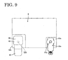
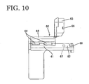
- a cover 60 is or can be fitted on or placed substantially over one terminal 50b so as to differentiate the length of a terminal portion from a terminal 50a having no cover. Accordingly, the lengths or longitudinal extensions or distances Da, Db of terminal accommodating portions 52a, 52b formed around electrode portions 51 a, 51 b are differed. If a correspondence between the terminals 50a, 50b and the electrode portions 51 a, 51 b is incorrect, the terminal 50b provided with the cover 60 cannot be fitted into the terminal accommodating portion 52a.
- the right one 52a of the terminal accommodating portions 52a, 52b around the electrode portions 51 a, 51 b in FIG. 8 is preferably substantially square in plan view, whereas the left one 52b is preferably substantially rectangular having a longer length.
- terminals 50a, 50b The same terminals as those of the embodiment are used as the terminals 50a, 50b. However, barrel portions are preferably formed straight without being bent.
- the cover 60 made of an insulating material is mounted on one terminal 50b (terminal for the (+)-electrode), i.e. the left one shown in FIG. 8.
- the cover 60 is integrally or unitarily comprised of a barrel accommodating portion 61 for accommodating the barrel portion 53b of the terminal 50b and a part of a battery cord or conductor 54, and a connecting portion accommodating portion 62 for accommodating a connecting portion 55 for connection with the electrode portion 51 b.
- the cover 60 is provided with a first lid 63 which is pivotal to substantially open and close about a hinged edge provided at one edge extending from the barrel accommodating portion 61 to the connecting portion accommodation portion 62.
- Two locking claws 64 are formed at an edge of the barrel accommodating portion 61 opposite from the hinged edge and are lockingly engageable with the outer surface of a base end when the first lid 63 is closed.
- the connecting portion accommodating portion 62 is provided with a second lid 65 for substantially opening and closing the connecting portion 55 of the terminal 50b.
- the second lid 65 is pivotal to substantially open and close about a hinged edge provided at a boundary with the first lid 63.
- a pair of locking projections 66 are formed on outer surfaces of the first lid 65 and are engaged with a pair of corresponding locking recesses 67 (only one recess 67 is shown in FIG. 10) to substantially close or lock the second lid 65, thereby covering substantially the entire surface of the connecting portion 55 of the terminal 50b.
- a stopper 68 projects at the leading end inside the connecting portion accommodating portion 62, so that it comes or can come into contact with the leading end of the terminal 50b to position the terminal 50b being accommodated.
- an unillustrated through hole is formed in agreement with an insertion hole 56b of the terminal 50b, so that a threaded shaft 57b of the electrode portion 51 b can be inserted through the insertion hole 56b via this through hole.
- a distance between the center of the insertion hole 56b of the terminal 50b provided with the cover 60 to the front edge of the cover 60 (front edge of the con-necting portion accommodating portion 62) is longer than a corresponding distance of the terminal 50a, i.e. a distance from the center of an insertion hole 56a to the front end of the terminal 50a.
- the terminal 50b provided with the cover 60 can be fitted into the left terminal accommodating portion 52b shown in FIGS. 8 and 9 and connected with the electrode portion 51 b. If an attempt is made to fit the terminal 50b into the right terminal accommodating portion 52a shown in FIGS. 8 and 9, the leading end of the cover 60 interferes the upper surface of the battery B due to an insufficient length of the terminal accommodating portion 52a. Thus, it is impossible to fit the terminal 50b into the terminal accommodating portion 52a, making an operator notice erroneous assembling.
- connection of the terminal 50a at the right side of FIGS. 8 and 9 is completed by inserting a threaded shaft 57a through the insertion hole 56a of the terminal 50a and screwing a nut 58 down on the threaded shaft 57a.
- the cover 60 is mounted on the terminal 50b and the battery cord 54 with the second lid 65 left open.
- the threaded shaft 57b is inserted through the insertion hole 56b via the through hole and screwing the nut 58 down on the threaded shaft 57b. If the second lid 65 is then closed and the locking projections 66 are engaged with the corresponding locking recesses 67, the second lid 65 is held closed.
- FIGS. 11 to 14 show a fourth comparative example FIG. 11 shows a portion of an inventive battery B near its electrode portions, and the battery B used here is preferably a 36V-battery (usually 12V-battery).
- the left and right corners of the battery B are recessed to form engaging portions 10a, 10b, and a (+)-electrode portion 11 a and a (-)-electrode portion 11 b are provided on the bottom surfaces of the engaging portions 10a, 10b.
- Both electrode por tions 10a, 10b are constructed such that threaded shafts 13a, 13b substantially vertically project through round washer rings or washers 12.
- the depth or height of the engaging portions 10a, 10b is preferably set such that the threaded shafts 13a, 13b do not project to the upper surface of the battery B.
- identification recesses 114a, 114b are formed in side walls of the respective engaging portions 10a, 10b, and preferably project inwardly substantially toward each other in the engaging portions 10a, 10b so as to be transversely symmetrical.
- the identification recesses 114a, 114b are formed such that they are preferably substantially symmetrical with respect to a line L transversely extending between the electrodes 11 a, 11b.
- terminals 15a, 15b to be connected with the electrode portions 11 a, 11 b are e.g. made of a conductive metallic material and each have a barrel portion 16 at its rear end for connection of a battery cord or conductor C by crimping.
- Front portions of the terminal 15a, 15b are base plates 117 which are bent at an angle different from 0° or 180°, preferably substantially at a right angle to the barrel portions 16, and are each formed substantially in its middle with an insertion hole 120 into which the threaded shaft 13a, 13b is insertable.
- the base plates 117 of the left and right terminals 15a, 15b are so formed as to be transversely symmetrical.
- transversely symmetrical identification pieces 117a, 117b project from side edges of the base plates 117 of the respective terminals 15a, 15b.
- the width of the identification pieces 117a, 117b is set larger than that of the identification recesses 114a, 114b.
- rotation preventing pieces 118a, 118b project from side edges of the base plates 117 opposite from the identification pieces 117a, 117b and act to prevent rotation of the entire terminals 15a, 15b in the case that the terminals 15a, 15b are fastened by screwing nuts 119 down on the threaded shafts 13.
- the rotation preventing pieces 118a, 118b are formed to have a narrower width than the identification pieces 117a, 117b so as to be at least partly fittable or insertable into the identification recesses 114a, 114b in the case that the terminals 15a, 15b and the electrode portions 11a, 11 b are in a correct correspondence.
- contact pieces 121a, 121b are formed by being bent upward for the purpose of enlarging contact areas with the identification recesses 114a, 114b.
- the fourth comparative example is constructed as above.
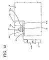
- the rotation preventing pieces 118a, 118b of the terminals 15a, 15b are or can be fitted or inserted into the corresponding identification recesses 114a, 114b. If the threaded shafts 13 are inserted into the insertion holes 120 and the base plates 117 are placed on the washer rings 12, the barrel portions 16 of the terminals 15a, 15b and the battery cords C preferably extend substantially along the side surfaces of the battery B. Connections or fastenings or mountings of the terminals 15a, 15b are completed by screwing the nuts 119 down on the threaded shafts 13 in this state.
- the terminals 15a, 15b try to rotate clockwise at a final stage of fastening. However, since the contact pieces 121a, 121 b of the rotation preventing pieces 118a, 118b come into contact with the facing surfaces of the identification recesses 114a, 114b to prevent rotation, fastening with the nuts 119 can be smoothly performed.
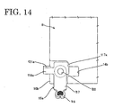
- the identification pieces 117a, 117b interfere the opening edges of the identification recesses 114a, 114b as shown in FIG. 14, with the result that the terminals 15a, 15b cannot be fitted into the engaging portions 10a, 10b.
- an operator notices the incorrect correspondence between the terminals 15a, 15b and the electrode portions 11a, 11b.
- the rotating preventing pieces 118a, 118b are formed with the contact pieces 121a, 121b to enlarge the contact areas with the wall surfaces of the identification recesses 114a, 114b, they will not bite in the wall surfaces of the identification recesses 114a, 114b, thereby protecting the battery B from damages or scratches.
- the battery B according to this comparative example has a special form in which the engaging portions 10a, 10b are formed around the electrode portions 11 a, 11 b, it preferably contributes to distinction from conventional 12V-batteries. Furthermore, since the depth or height of the engaging portions 10a, 10b is set such that the threaded shafts 13a, 13b do not project to the upper surface of the battery B, there is also an effect of avoiding an inadvertent contact of a tool or the like with the threaded shafts.
- FIGS. 15 to 17 show a fifth comparative example.
- identification pieces 127a, 127b also act as rotation preventing pieces.
- Terminals 125a, 125b of the fifth comparative example are formed with the identification pieces 127a, 127b projecting from the leading edges thereof preferably substantially in longitudinal direction.
- the terminals 125a, 125b are formed to be transversely symmetrical, and each identification piece 127a, 127b is formed in a position displaced toward one of the opposite side edges of a base plate.
- Leading ends of the identification pieces 127a, 127b are bent at an angle different from 0° or 180°, preferably substantially normal or upward to form contact pieces 129a, 129b.
- the contact pieces 121a, 121b are brought or bringable substantially into surface contact with the wall surfaces of the identification recesses 14a, 14b in the fifth embodiment, the side edges of the contact pieces 129a, 129b are brought into contact with the wall surfaces of identification recesses 124a, 124b to effectively prevent the rotation of the entire terminals 125a, 125b in the fifth comparative example.
- the identification recesses 124a, 124b are formed in the back or lateral wall surfaces of engaging portions 122a, 122b in positions substantially corresponding to the identification pieces 127a, 127b of the terminals 125a, 125b arranged in a correct combination.
- the engaging portions 122a, 122b are transversely symmetrical.
- the other construction is the same or similar as in the fourth comparative example
- the terminals 125a, 125b cannot be connected since the identification pieces 127a, 127b do not match the identification recesses 124a, 124b and interfere the peripheries of the identification recesses 124a, 124b or interact therewith.
- rotation of the terminals 125a, 125b can be prevented by the side edges of the contact pieces 129a, 129b coming into contact with the wall surfaces of the identification recesses 124a, 124b during fastening with nuts 119 at the time of proper assembling.
- the constructions of the terminals and the battery can be simplified since the identification pieces 127a, 127b act also as rotation preventing pieces.
- FIGS. 18 to 20 show a sixth comparative example.
- a cover CO is fitted on or substantially over one terminal 135b so as to differentiate the lengths of portions of the terminals to be accommodated in engaging portions 130a, 130b.
- lengths of the engaging portions 130a, 130b are differed (L1 ⁇ L2), so that the terminal 135b provided with the cover CO cannot be fitted into the unmatching engaging portion 130a in the case of an incorrect correspondence between the terminals 135a, 135b and electrode portions 131 a, 131 b.
- the cover CO preferably made of an insulating material such as a synthetic resin is mounted on one 135b (terminal for the (+)-electrode) of the terminals 135a, 135b, i.e. the left one shown in FIGS. 18 and 19.
- the cover CO is integrally or unitarily comprised of a barrel accommodating portion CO1 for accommodating a barrel portion 16 of the terminal 135b and a part of a battery cord or conductor or connection C, and a connecting portion accommodating portion CO2 which is continuous with and bent from the barrel accommodating portion CO1 and is adapted to accommodate a connecting portion 140 for connection with the electrode portion 131b.
- the cover CO is provided with a first lid 141 which is pivotal to substantially open and close about a hinged edge (not shown in detail) provided at one edge extending from the barrel accommodating portion CO1 to the connecting portion accommodation portion CO2.
- Two locking claws 143 are formed at an edge of the barrel accommodating portion CO1 preferably substantially opposite from the hinged edge and are lockingly engageable with the outer surface of a base end when the first lid 141 is closed.
- the connecting portion accommodating portion CO2 is provided with a second lid 142 for opening and closing the connecting portion 140 of the terminal 135b.
- the second lid 142 is pivotal to open and close about a hinged edge 144 provided at a boundary with the first lid 141.
- a pair of locking projections 145 are preferably formed on outer surfaces of the first lid 142 and are engaged or engageable with a pair of corresponding locking recesses 146 to substantially close the second lid 142, thereby substantially covering the entire surface of the connecting portion 140 of the terminal 135b.
- a stopper 147 projects at the leading end inside the connecting portion accommodating portion CO2, so that it comes into contact with the leading end of the terminal 135b to substantially position the terminal 135b being accommodated.
- an unillustrated through hole is formed in agreement with an insertion hole of the terminal 135b, so that a threaded shaft 13 of the electrode portion 31b can be inserted through the insertion hole 120 via this through hole.
- an escape hole 149 for drawing a rotation preventing piece 138b and a contact piece 148b of the terminal 135b out of the cover CO is formed in the corresponding portion, preferably the bottom end of a side wall at a base portion of the connecting portion accommodating portion CO2.
- the terminal 135a is or can be connected in such a manner as described above at the side of the (-)-electrode (located at the right side in FIG. 18).
- the terminal 35b is at least partly accommodated in the cover CO with the first and second lids 141, 142 left open, and the first lid 141 is or can be first closed and locked by the locking claws 143.
- the rotation preventing piece 138b of the terminal 135b projects out of the cover CO through the escape hole 149.
- the threaded shaft 13 is inserted or insertable through the insertion hole 120 via the unillustrated through hole formed in the bottom wall of the cover CO. Then, the rotation preventing piece 138b is fitted or fittable into the identification recess 134b.
- the nut 119 can be smoothly screwed since rotation of the entire terminal is prevented by the engagement of the contact piece 148b of the rotation preventing piece 138b with the wall surface. If the second lid 142 is closed to engage the locking projections 145 with the corresponding locking recesses 146 after completing fastening with the nut 119, the second lid 146 is or can be held substantially closed.
- the terminal 135b provided with the cover CO cannot be fitted into the engaging portion 130a. This is because, even if an attempt is made, for example, to assemble the terminal provided with the cover CO with the (-)-electrode by, i.e. adjusting the position of the unillustrated through hole to match that of the threaded shaft, the leading end of the cover CO interferes the upper surface of the battery B due to an insufficient length of the engaging portion 130a at the side of the (-)-electrode. Therefore, erroneous assembling can be securely avoided also in the sixth comparative example. Particularly, deformation of the cover CO can be prevented since a fastening torque of the nut 19 is received by the rotation preventing piece 138b drawn out of the cover CO in the sixth comparative example.
Landscapes
- Connection Of Batteries Or Terminals (AREA)
- Battery Mounting, Suspending (AREA)
- Charge And Discharge Circuits For Batteries Or The Like (AREA)
- Details Of Connecting Devices For Male And Female Coupling (AREA)
Description
- The present invention relates to a construction for preventing erroneous assembling of battery terminals, to a battery and to a set of terminals for the connection therewith.
- Generally, shafts project as a (+)-electrode and a (-)-electrode from the upper surface of an automotive battery, and these shafts are connected with each other by being inserted into round holes of terminals connected with a battery cord and fastening the terminals thereto with nuts or the like.
- However, since the battery terminals are connectable with either one of the electrodes due to their constructions, they may be connected with incorrect electrodes.
- From GB-A-700,131 an accumulator and batteries are known, at which a "U"-shaped and a "J"-shaped insulating member projects from the block of the battery, each having a step within its limbs. In order do distinguish between the two end terminals of the battery, the screw-threaded aperture in the one step has a somewhat larger diameter than that in the other step and the corresponding metal terminal screw is of corresponding larger size than the other screw.
- From EP-A-0 349 473 a battery is known, at which the terminals are provided with connecting lines ending at connectors at the edge of the battery.
- From US-A-4,064,328 an auxiliary dual battery terminal having conventional tapered post and screwthreaded stud upstanding from a generally flat generally triangular or T-shaped body in spaced relation to its mounting collar for connecting an electrical conductor is known.
- From DE-A-2 028 012 a battery is known at which a connector having different forms of connector pins is know.
- From US-A-3,980,388 a battery snap terminal is known, at which male polarized terminals and female polarized terminals are provided.
- From US-A-5,672,442 a battery terminal and a post with rotating inhibiting means is known, at which recesses are combined with an angled shape of alignment tabs to prevent the terminal from being inadvertently connected to the post in a position 180° away from the desired angular orientation.
- It is the object of the invention to provide a construction capable of securely preventing erroneous assembling of battery terminals and also to provide a battery and a set of terminals for connection therewith.
- This object is fulfilled by a construction having the features disclosed in
claim 1. Preferred embodiments are defined in the dependent subclaims. - According to the invention, there is provided a construction for preventing erroneous assembling of battery terminals to correctly assemble the terminals with corresponding (-)-electrode portion and (+)-electrode portion of a battery, wherein both the two terminals and the two electrode portions comprise identification means for enabling assembling only in the case of a correct correspondence of the terminals and the electrode portions while making it impossible to assemble the terminals with the electrode portions in the case of an incorrect correspondence.
- Accordingly, erroneous assembling can be securely prevented since the identification means enables assembling of the terminals and the electrode portions in the case of the correct correspondence while making it impossible to assemble the terminals with the electrode portions not corresponding thereto.
- In addition, since such an identification means is provided in the battery, the battery can be easily distinguished in appearance from those of existing standards if it has new standards.
- The identification means of the electrode portions comprises a threaded shaft provided in one electrode portion and a nut provided in the other electrode portion, and the identification means of the terminals comprises a nut which is provided in the terminal corresponding to the one electrode portion having the threaded shaft and can be screwed down on the threaded shaft, and a threaded shaft which is provided in the terminal corresponding to the other electrode portion having the nut and is engageable with the nut of the other electrode portion.
- Accordingly, in the case of the incorrect correspondence between the terminals and the electrode portions, it results in a combination of the threaded shafts or a combination of nuts. Thus, the terminals and the electrodes cannot be assembled.
- Preferably, the identification means of the terminals comprises a cover which is provided separately from the terminal and is to be mounted or mountable on or over the terminal.
- Accordingly, connection of the terminals and the electrode portions not corresponding to each other is prohibited by the identification means.
- Most preferably, the identification means of the electrode portions comprises a terminal accommodating portion for enabling accommodation of the terminal provided with the cover by confirming or corresponding to the cover in the case of a correct correspondence between the terminals and the electrode portions while making it impossible to connect the terminals with the electrode portions by causing the cover to interfere the battery, preferably an upper surface of the battery in the case of an incorrect correspondence.
- Accordingly, erroneous assembling of the terminal provided the cover with the electrode portion not corresponding thereto can be avoided by the identification means of the electrode portions.
- According to a further preferred embodiment of the invention, the construction further comprises rotation preventing means for preventing rotation of the terminals with respect to the corresponding electrode portions by mutual engagement.
- These and other objects, features and advantages of the present invention will become more apparent upon reading of the following detailed description of preferred embodiments and accompanying drawings.
- FIG. 1 is an exploded perspective view showing an assembling construction of a comparative example
- FIG. 2 is a plan view showing an assembled state of an engaging portion and a terminal,
- FIG. 3 is a side view showing the assembled state of the engaging portion and the terminal,
- FIG. 4 is an exploded perspective view showing an assembling construction of an embodiment, of the invention
- FIG. 5 is a plan view showing an assembled state of an engaging portion and a terminal,
- FIG. 6 is an exploded perspective view showing an assembling construction of a comparative example
- FIG. 7 is a plan view showing an assembled state of an engaging portion and a terminal,
- FIG. 8 is an exploded perspective view showing an assembling construction of a comparative example,
- FIG. 9 is a plan view showing an assembled state of an engaging portion and a terminal,
- FIG. 10 is a side view of a cover with a second lid left open,
- FIG. 11 is an exploded perspective view showing an assembling construction of a comparative example,
- FIG. 12 is a plan view showing an assembled state of an engaging portion and a terminal,
- FIG. 13 is a side view showing the assembled state of the engaging portion and the terminal,
- FIG. 14 is a plan view showing a case of erroneous assembling,
- FIG. 15 is an exploded perspective view showing an assembling construction of a comparative example,
- FIG. 16 is a plan view showing an assembled state of an engaging portion and a terminal,
- FIG. 17 is a plan view showing a case of erroneous assembling,
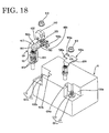
- FIG. 18 is an exploded perspective view showing an assembling construction of a comparative example,
- FIG. 19 is a plan view showing an assembled state of an engaging portion and a terminal, and
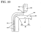
- FIG. 20 is a side view of a cover with a second lid left open.
- Hereinafter, a preferred embodiment of the invention as well as several comparative examples not belonging to the invention are described with reference to the accompanying drawings.
- FIGS. 1 to 3 show a first comparative example FIG. 1 shows a portion of an inventive battery B near its electrode portions, and the battery B used here is e.g. a 36V-battery (usually 12V-battery). As shown in FIG. 1, the left and right corners of the battery B are recessed to form recessed or electrode or engaging
portions electrode portion 11a and a (-)-electrode portion 11b are provided on the first or bottom surfaces of theengaging portions electrode portions shafts washers 12 preferably in the form of a square flat plate as shown in FIG. 1. The depth of theengaging portions shafts second recesses engaging portions corresponding recesses engaging portions corresponding recesses recesses - On the other hand,
terminals electrode portions barrel portion 16 at its rear end for connection of a battery cord or conductor C preferably by crimping. Front portions of theterminal base plates 17 which are bent at an angle different from 0° or 180°, preferably substantially at a right angle to thebarrel portions 16, and are each formed in its middle with aninsertion hole 18 into or through which the threadedshaft base plates 17 of the left andright terminals identification pieces base plates 17 of therespective terminals identification pieces base plates 17, and are selectively fittable or insertable into the first orsecond recesses identification pieces right terminals right terminals left electrode portions identification pieces terminals electrode portions terminals electrode portions identification pieces second recesses terminals electrode portions identification pieces recesses - Side ends of the
terminals 15a, 15 from theidentification pieces base plates 17 are bent downward at an angle different from 0° or 180°, preferably substantially at right angles, thereby forming firstrotation preventing pieces base plates 17 opposite from the firstrotation preventing pieces rotation preventing pieces rotation preventing pieces washers 12 are or can be tightly held by or interact with the first and secondrotation preventing pieces terminals nuts 22 are screwed down on the threadedshafts - The first comparative example is constructed as described above. If the correspondence between the
terminals electrode portions identification pieces second recesses washers 12 are tightly held by or interact with the first and secondrotation preventing pieces shafts insertion holes 18. If thenuts 22 are screwed down on the threadedshafts base plates 17 and thewashers 12 held in close contact, theterminals terminals rotation preventing pieces terminals electrode portions - In the case of an incorrect correspondence between the
terminals electrode portions identification pieces second recesses terminals portions terminals - As described above, erroneous assembling of the
terminals identification pieces recesses portions electrode portions portions shafts - FIGS. 4 and 5 show a preferred embodiment of the invention. In this embodiment, one (left one in FIG. 4) of
electrode portions shaft 33b similar to the first embodiment, whereas the other is such that anut 33a is embedded in awasher 32. Around theelectrode portions rectangular recesses recesses rotation preventing pieces washers 32. Further, a bolt (threaded shaft) 34 is made integral or unitary to oneterminal 35a (right one in FIG. 4) preferably by a temporary locking mechanism not shown in detail while having its rotation permitted. For example, the temporary locking mechanism may be such that the lower surface of a head of thebolt 34 and a base plate of the terminal 35a is slightly connected by, e.g. welding and this welded part is broken as thebolt 34 is screwed or may be such that a claw for softly engaging a thread of the bolt is formed at the edge of the insertion hole. Alternatively or additionally, thebolt 34 may be formed with a recess which engages the base plate of the terminal 35a so as to allow for a further rotation of thebolt 34 while longitudinally or axially positioning or holding it with respect to the base plate. - In the embodiment thus constructed, if a correspondence between the
terminals electrode portions electrode portion 31 b having the threadedshaft 33a with anut 39, whereas the terminal 35 can be fastened to the electrode portion 31 having the embeddednut 33b by screwing thebolt 34 thereof into thenut 33b. - However, if the correspondence between the
terminals electrode portions bolt 34 and theelectrode portion 31 b having the threadedshaft 33b are combined, and the terminal 35b, which should be fastened with thenut 39, and theelectrode portion 31 a having the embeddednut 33a are combined. In either combination, connection is impossible, with the result that erroneous assembling is immediately known to an operator. - Although the bolt coupled to the terminal by the temporary locking mechanism is shown in this embodiment, the nut may be similarly temporarily coupled.
- The other construction is the same or similar as in the first comparative example and, accordingly, the same function and result can be obtained.
- FIGS. 6 and 7 shows a second comparative
example Electrode portions shafts key receiving portions -
Insertion holes base plates 47 of theterminals shafts key portion 46 selectively fittable into thekey receiving portions base plate 47 of the terminal 45b formed with thelarger insertion hole 48b. If an attempt is made to assemble the terminal 45b formed with thekey portion 46 with theelectrode portion 41 a which does not correspond to the terminal 45b, thekey portion 46 cannot be fitted in by interfering the upper surface of the battery B. - In the case that the terminal 45a having the smaller one of the
insertion holes electrode portion 41a, it can be mounted on a washer in either position matching the assembled position (positions when thekey portion 46 is fitted into the first or secondkey receiving portion 48, 49) of theother terminal 45b. - In the second comparative example thus constructed as well, if a correspondence between the
terminals electrode portions smaller insertion hole 48a with theelectrode portion 41a having the thicker threadedshaft 43b, the threadedshaft 43b cannot be inserted through theinsertion hole 48a. Although the thinner threadedshaft 43a is insertable through the terminal 45b having thelarger insertion hole 48b, thekey portion 46 of thisterminal 45a interferes the upper surface of the battery B at the engaging portion having nokey receiving portions - The other construction is the same or similar as in the first comparative example and, accordingly, the same function and result can be obtained.
- FIGS. 8 to 10 show a third comparative example. In the third comparative example, a
cover 60 is or can be fitted on or placed substantially over oneterminal 50b so as to differentiate the length of a terminal portion from a terminal 50a having no cover. Accordingly, the lengths or longitudinal extensions or distances Da, Db of terminalaccommodating portions electrode portions terminals electrode portions cover 60 cannot be fitted into theterminal accommodating portion 52a. - Specifically, the right one 52a of the terminal
accommodating portions electrode portions - The same terminals as those of the embodiment are used as the
terminals - The
cover 60 made of an insulating material is mounted on oneterminal 50b (terminal for the (+)-electrode), i.e. the left one shown in FIG. 8. Thecover 60 is integrally or unitarily comprised of abarrel accommodating portion 61 for accommodating thebarrel portion 53b of the terminal 50b and a part of a battery cord orconductor 54, and a connectingportion accommodating portion 62 for accommodating a connectingportion 55 for connection with theelectrode portion 51 b. Thecover 60 is provided with afirst lid 63 which is pivotal to substantially open and close about a hinged edge provided at one edge extending from thebarrel accommodating portion 61 to the connectingportion accommodation portion 62. Two lockingclaws 64 are formed at an edge of thebarrel accommodating portion 61 opposite from the hinged edge and are lockingly engageable with the outer surface of a base end when thefirst lid 63 is closed. The connectingportion accommodating portion 62 is provided with asecond lid 65 for substantially opening and closing the connectingportion 55 of the terminal 50b. Thesecond lid 65 is pivotal to substantially open and close about a hinged edge provided at a boundary with thefirst lid 63. A pair of lockingprojections 66 are formed on outer surfaces of thefirst lid 65 and are engaged with a pair of corresponding locking recesses 67 (only onerecess 67 is shown in FIG. 10) to substantially close or lock thesecond lid 65, thereby covering substantially the entire surface of the connectingportion 55 of the terminal 50b. Astopper 68 projects at the leading end inside the connectingportion accommodating portion 62, so that it comes or can come into contact with the leading end of the terminal 50b to position the terminal 50b being accommodated. In the bottom wall of the connectingportion accommodating portion 62, an unillustrated through hole is formed in agreement with aninsertion hole 56b of the terminal 50b, so that a threadedshaft 57b of theelectrode portion 51 b can be inserted through theinsertion hole 56b via this through hole. - A distance between the center of the
insertion hole 56b of the terminal 50b provided with thecover 60 to the front edge of the cover 60 (front edge of the con-necting portion accommodating portion 62) is longer than a corresponding distance of the terminal 50a, i.e. a distance from the center of aninsertion hole 56a to the front end of the terminal 50a. Thus, the terminal 50b provided with thecover 60 can be fitted into the leftterminal accommodating portion 52b shown in FIGS. 8 and 9 and connected with theelectrode portion 51 b. If an attempt is made to fit the terminal 50b into the rightterminal accommodating portion 52a shown in FIGS. 8 and 9, the leading end of thecover 60 interferes the upper surface of the battery B due to an insufficient length of theterminal accommodating portion 52a. Thus, it is impossible to fit the terminal 50b into theterminal accommodating portion 52a, making an operator notice erroneous assembling. - In the third comparative example thus constructed, if a correspondence between the
terminals electrode portions shaft 57a through theinsertion hole 56a of the terminal 50a and screwing anut 58 down on the threadedshaft 57a. At the left side of FIGS. 8 and 9, thecover 60 is mounted on the terminal 50b and thebattery cord 54 with thesecond lid 65 left open. In this state, the threadedshaft 57b is inserted through theinsertion hole 56b via the through hole and screwing thenut 58 down on the threadedshaft 57b. If thesecond lid 65 is then closed and the lockingprojections 66 are engaged with the corresponding locking recesses 67, thesecond lid 65 is held closed. - In the case of an incorrect correspondence between the
terminals electrode portions cover 60 cannot be fitted into the rightterminal accommodating portion 52a shown in FIGS. 8 and 9. This is because the leading end of thecover 60 interferes the upper surface of the battery B or the threadedshaft 57b does not match the through hole if an attempt is made to fit the terminal 50b into theterminal accommodating portion 52a without interference of thecover 60 with the upper surface of the battery B since the rightterminal accommodating portion 52a is shorter than the leftterminal accommodating portion 52b. Therefore, erroneous assembling can be securely avoided also in the third comparative example - FIGS. 11 to 14 show a fourth comparative example FIG. 11 shows a portion of an inventive battery B near its electrode portions, and the battery B used here is preferably a 36V-battery (usually 12V-battery). As shown in FIG. 11, the left and right corners of the battery B are recessed to form engaging
portions electrode portion 11 a and a (-)-electrode portion 11 b are provided on the bottom surfaces of the engagingportions shafts washers 12. The depth or height of the engagingportions shafts portions portions electrodes - On the other hand,
terminals electrode portions barrel portion 16 at its rear end for connection of a battery cord or conductor C by crimping. Front portions of the terminal 15a, 15b arebase plates 117 which are bent at an angle different from 0° or 180°, preferably substantially at a right angle to thebarrel portions 16, and are each formed substantially in its middle with aninsertion hole 120 into which the threadedshaft base plates 117 of the left andright terminals symmetrical identification pieces base plates 117 of therespective terminals identification pieces terminals electrode portions identification pieces terminals - Further,
rotation preventing pieces base plates 117 opposite from theidentification pieces entire terminals terminals nuts 119 down on the threadedshafts 13. Therotation preventing pieces identification pieces terminals electrode portions rotation preventing pieces terminals nut 119 is screwed,contact pieces - The fourth comparative example is constructed as above. In the case of a correct correspondence between the
terminals rotation preventing pieces terminals shafts 13 are inserted into the insertion holes 120 and thebase plates 117 are placed on the washer rings 12, thebarrel portions 16 of theterminals terminals nuts 119 down on the threadedshafts 13 in this state. Theterminals contact pieces rotation preventing pieces nuts 119 can be smoothly performed. - In the case of an incorrect correspondence between the
terminals electrode portions identification pieces terminals portions terminals electrode portions - As described above, according to the fourth comparative example, whether the correspondence between the
terminals electrode portions identification pieces pieces nuts 119, fastening can be smoothly and easily performed. Furthermore, since the rotating preventingpieces contact pieces - Further, since the battery B according to this comparative example has a special form in which the engaging
portions electrode portions portions shafts - FIGS. 15 to 17 show a fifth comparative example. In this embodiment,
identification pieces -
Terminals identification pieces terminals identification piece identification pieces contact pieces contact pieces contact pieces identification recesses entire terminals - Specifically, the identification recesses 124a, 124b are formed in the back or lateral wall surfaces of engaging
portions identification pieces terminals portions - The other construction is the same or similar as in the fourth comparative example
- In the fifth comparative example thus constructed as well, if an attempt is made to connect the
terminals terminals identification pieces terminals contact pieces nuts 119 at the time of proper assembling. Further, the constructions of the terminals and the battery can be simplified since theidentification pieces - FIGS. 18 to 20 show a sixth comparative example.
- In the sixth comparative example, a cover CO is fitted on or substantially over one
terminal 135b so as to differentiate the lengths of portions of the terminals to be accommodated in engagingportions portions unmatching engaging portion 130a in the case of an incorrect correspondence between theterminals electrode portions - As described above, the cover CO preferably made of an insulating material such as a synthetic resin is mounted on one 135b (terminal for the (+)-electrode) of the
terminals - The cover CO is integrally or unitarily comprised of a barrel accommodating portion CO1 for accommodating a
barrel portion 16 of the terminal 135b and a part of a battery cord or conductor or connection C, and a connecting portion accommodating portion CO2 which is continuous with and bent from the barrel accommodating portion CO1 and is adapted to accommodate a connecting portion 140 for connection with theelectrode portion 131b. The cover CO is provided with afirst lid 141 which is pivotal to substantially open and close about a hinged edge (not shown in detail) provided at one edge extending from the barrel accommodating portion CO1 to the connecting portion accommodation portion CO2. Two locking claws 143 are formed at an edge of the barrel accommodating portion CO1 preferably substantially opposite from the hinged edge and are lockingly engageable with the outer surface of a base end when thefirst lid 141 is closed. - The connecting portion accommodating portion CO2 is provided with a
second lid 142 for opening and closing the connecting portion 140 of the terminal 135b. Thesecond lid 142 is pivotal to open and close about a hingededge 144 provided at a boundary with thefirst lid 141. A pair of locking projections 145 (only one projection is shown in FIG. 18) are preferably formed on outer surfaces of thefirst lid 142 and are engaged or engageable with a pair of corresponding locking recesses 146 to substantially close thesecond lid 142, thereby substantially covering the entire surface of the connecting portion 140 of the terminal 135b. - A stopper 147 projects at the leading end inside the connecting portion accommodating portion CO2, so that it comes into contact with the leading end of the terminal 135b to substantially position the terminal 135b being accommodated. In the bottom wall of the connecting portion accommodating portion CO2, an unillustrated through hole is formed in agreement with an insertion hole of the terminal 135b, so that a threaded
shaft 13 of theelectrode portion 31b can be inserted through theinsertion hole 120 via this through hole. As shown in FIG. 20, anescape hole 149 for drawing arotation preventing piece 138b and acontact piece 148b of the terminal 135b out of the cover CO is formed in the corresponding portion, preferably the bottom end of a side wall at a base portion of the connecting portion accommodating portion CO2. - As described above, in the sixth comparative example thus constructed, if a correspondence between the
terminals electrode portions second lids first lid 141 is or can be first closed and locked by the locking claws 143. At this stage, therotation preventing piece 138b of the terminal 135b projects out of the cover CO through theescape hole 149. In such a state, the threadedshaft 13 is inserted or insertable through theinsertion hole 120 via the unillustrated through hole formed in the bottom wall of the cover CO. Then, therotation preventing piece 138b is fitted or fittable into theidentification recess 134b. - Thereafter, the
nut 119 can be smoothly screwed since rotation of the entire terminal is prevented by the engagement of thecontact piece 148b of therotation preventing piece 138b with the wall surface. If thesecond lid 142 is closed to engage the lockingprojections 145 with the corresponding locking recesses 146 after completing fastening with thenut 119, thesecond lid 146 is or can be held substantially closed. - In the case of an incorrect correspondence between the
terminals electrode portions portion 130a. This is because, even if an attempt is made, for example, to assemble the terminal provided with the cover CO with the (-)-electrode by, i.e. adjusting the position of the unillustrated through hole to match that of the threaded shaft, the leading end of the cover CO interferes the upper surface of the battery B due to an insufficient length of the engagingportion 130a at the side of the (-)-electrode. Therefore, erroneous assembling can be securely avoided also in the sixth comparative example. Particularly, deformation of the cover CO can be prevented since a fastening torque of thenut 19 is received by therotation preventing piece 138b drawn out of the cover CO in the sixth comparative example. - Various changes can be made in the present invention, and following embodiments are also embraced by the technical scope of the present invention as defined in the claims.
-
- 10a, 10b ...
- engaging portion
- 11 a, 11 b, 31 a, 31 b, 41 a, 41b, 51a, 51b ...
- electrode portion
- 13a, 13b, 33a, 33b, 43a, 43b, 57a, 57b ...
- threaded shaft
- 15a, 15b, 35a, 35b, 45a, 45b, 50a, 50b ...
- terminal
- 18, 38, 48a, 48b, 56a, 56b ...
- insertion hole
- 19a, 19b ...
- identification piece
- 46 ...
- key portion
- 48, 49...
- key receiving portion
- 60 ...
- cover
- 122a, 122b, 130a, 130b ...
- engaging portion
- 123a, 123b, 131a, 131b ...
- electrode portion
- 124a, 124b, 134a, 134b ...
- identification recess
- 125a, 125b, 135a, 135b ...
- terminal
- 117a, 117b, 127a, 127b ...
- identification piece
- 118a, 118b, 138a, 138b ...
- rotation preventing piece
- 119 ...
- nut
- 120 ...
- insertion hole
- 121a, 121b ...
- contact piece
- CO ...
- cover
Claims (4)
- A construction for preventing erroneous assembling of two battery terminals (35) to correctly assemble the terminals (35) with a corresponding minus-electrode and plus-electrode at electrode portions (31) of a battery (B), wherein the two terminals (35) and the two electrode portions (31) comprise identification means (33, 34, 39) for enabling assembling only in the case of a correct correspondence of the terminals (35) and the electrode portions (31) while making it impossible to assemble the terminals (35) with the electrode portions (31) in the case of an incorrect correspondence,
characterized in that the identification means (33, 34, 39) of the electrode portions (31) comprises a threaded shaft (33b) provided in one electrode portion (31 b) and a nut (33a) provided in the other electrode portion (31a), and the identification means (33, 34, 39) of the terminals (35) comprises a nut (39) which is provided in the terminal (35b) corresponding to the one electrode portion (31 b) having the threaded shaft (33b) and can be screwed down on the th threaded shaft (33b), and a threaded shaft (34) which is provided in the terminal (35a) and made integral therewith while having its rotation permitted and corresponding to the other electrode portion (31a) having the nut (33a) and is engageable with the nut (33a) of the other electrode portion (31a). - The construction according to claim 1, wherein the identification means (33, 34, 39) of the terminals (35) further comprises a cover which is provided separately from the terminal and is mounted or mountable on or over the terminal.
- The construction according to claim 2, wherein the identification means (33, 34, 39) of the electrode portions (31) further comprises a terminal accommodating portion for enabling accommodation of the terminal provided with the cover by corresponding to the cover in the case of a correct correspondence between the terminals and the electrode portions while making it impossible to connect the terminals with the electrode portions by causing the cover to interfere the battery (B), preferably an upper surface thereof in the case of an incorrect correspondence.
- The construction according to one or more of the preceding claims, further comprising rotation preventing means (36) for preventing rotation of the terminals (35) with respect to the corresponding electrode portions (31) by mutual engagement.
Priority Applications (3)
| Application Number | Priority Date | Filing Date | Title |
|---|---|---|---|
| EP05001227A EP1526609B1 (en) | 2000-03-07 | 2001-03-06 | A construction for preventing erroneous assembling of battery terminals, a battery and a set of terminals |
| EP05001228A EP1526610B1 (en) | 2000-03-07 | 2001-03-06 | A construction for preventing erroneous assembling of battery terminals, a battery and a set of terminals |
| EP05001226A EP1531521B1 (en) | 2000-03-07 | 2001-03-06 | A construction for preventing erroneous assembling of battery terminals, a battery and a set of terminals |
Applications Claiming Priority (4)
| Application Number | Priority Date | Filing Date | Title |
|---|---|---|---|
| JP2000062439A JP2001250533A (en) | 2000-03-07 | 2000-03-07 | Structure for preventing battery terminals from being incorrectly assembled and batteries |
| JP2000062439 | 2000-03-07 | ||
| JP2000080121 | 2000-03-22 | ||
| JP2000080121A JP2001266967A (en) | 2000-03-22 | 2000-03-22 | Structure to prevent incorrect assembly of battery terminals |
Related Child Applications (3)
| Application Number | Title | Priority Date | Filing Date |
|---|---|---|---|
| EP05001227A Division EP1526609B1 (en) | 2000-03-07 | 2001-03-06 | A construction for preventing erroneous assembling of battery terminals, a battery and a set of terminals |
| EP05001226A Division EP1531521B1 (en) | 2000-03-07 | 2001-03-06 | A construction for preventing erroneous assembling of battery terminals, a battery and a set of terminals |
| EP05001228A Division EP1526610B1 (en) | 2000-03-07 | 2001-03-06 | A construction for preventing erroneous assembling of battery terminals, a battery and a set of terminals |
Publications (3)
| Publication Number | Publication Date |
|---|---|
| EP1156552A2 EP1156552A2 (en) | 2001-11-21 |
| EP1156552A3 EP1156552A3 (en) | 2001-11-28 |
| EP1156552B1 true EP1156552B1 (en) | 2006-06-21 |
Family
ID=26586953
Family Applications (4)
| Application Number | Title | Priority Date | Filing Date |
|---|---|---|---|
| EP01105306A Expired - Lifetime EP1156552B1 (en) | 2000-03-07 | 2001-03-06 | A construction for preventing erroneous assembling of battery terminals, a battery and a set of terminals |
| EP05001228A Expired - Lifetime EP1526610B1 (en) | 2000-03-07 | 2001-03-06 | A construction for preventing erroneous assembling of battery terminals, a battery and a set of terminals |
| EP05001226A Expired - Lifetime EP1531521B1 (en) | 2000-03-07 | 2001-03-06 | A construction for preventing erroneous assembling of battery terminals, a battery and a set of terminals |
| EP05001227A Expired - Lifetime EP1526609B1 (en) | 2000-03-07 | 2001-03-06 | A construction for preventing erroneous assembling of battery terminals, a battery and a set of terminals |
Family Applications After (3)
| Application Number | Title | Priority Date | Filing Date |
|---|---|---|---|
| EP05001228A Expired - Lifetime EP1526610B1 (en) | 2000-03-07 | 2001-03-06 | A construction for preventing erroneous assembling of battery terminals, a battery and a set of terminals |
| EP05001226A Expired - Lifetime EP1531521B1 (en) | 2000-03-07 | 2001-03-06 | A construction for preventing erroneous assembling of battery terminals, a battery and a set of terminals |
| EP05001227A Expired - Lifetime EP1526609B1 (en) | 2000-03-07 | 2001-03-06 | A construction for preventing erroneous assembling of battery terminals, a battery and a set of terminals |
Country Status (3)
| Country | Link |
|---|---|
| US (1) | US6398595B2 (en) |
| EP (4) | EP1156552B1 (en) |
| DE (4) | DE60125428T2 (en) |
Families Citing this family (36)
| Publication number | Priority date | Publication date | Assignee | Title |
|---|---|---|---|---|
| EP1239506B1 (en) * | 2001-03-07 | 2012-04-25 | Yazaki Corporation | Protective cover and fuse box |
| JP2003284220A (en) * | 2002-03-20 | 2003-10-03 | Yazaki Corp | Arc discharge prevention member |
| JP2003317823A (en) * | 2002-04-25 | 2003-11-07 | Yazaki Corp | Terminal protection cap |
| DE10311213A1 (en) * | 2003-03-14 | 2004-09-23 | Volkswagen Ag | A cable shoe for arranging on a pin of an electric connector e.g. in on-board networks in vehicles, has a tongue in shape fitting engagement with a flange |
| DE102004052476B4 (en) * | 2003-10-31 | 2007-08-09 | Yazaki Corp. | fuse assembly |
| KR100846074B1 (en) * | 2005-05-09 | 2008-07-14 | 주식회사 엘지화학 | Three-dimensional electrode terminal of pouch type battery |
| JP4527042B2 (en) * | 2005-10-21 | 2010-08-18 | 矢崎総業株式会社 | Electrical junction box |
| US7597574B2 (en) * | 2006-08-11 | 2009-10-06 | Asm America, Inc. | Lamp fasteners for semiconductor processing reactors |
| US7663466B1 (en) * | 2007-09-21 | 2010-02-16 | Yazaki North America, Inc. | Corner-mounted battery fuse |
| JP5128902B2 (en) * | 2007-10-31 | 2013-01-23 | 矢崎総業株式会社 | Assembly structure of fusible link unit |
| JP5225805B2 (en) * | 2008-10-27 | 2013-07-03 | 日立ビークルエナジー株式会社 | Secondary battery and manufacturing method thereof |
| EP2347472B1 (en) * | 2008-11-20 | 2015-03-18 | Telefonaktiebolaget L M Ericsson (PUBL) | Method and device for facilitating connection to a battery |
| US7695326B1 (en) * | 2008-11-20 | 2010-04-13 | Royal Die & Stamping | Lever lock battery terminal |
| FR2941098A1 (en) * | 2009-01-09 | 2010-07-16 | Peugeot Citroen Automobiles Sa | Electric members e.g. power inverter, connecting device for electric/hybrid motor vehicle, has single combination of pairings between connection terminals and connection cells to allow assembly of connection terminals in connection cells |
| FR2945156A1 (en) * | 2009-04-30 | 2010-11-05 | Peugeot Citroen Automobiles Sa | Electric connection lug for motor vehicle, has part connected to connection portion and conformed as biasing part, where biasing part is engaged in integrated complementary track of connection terminal |
| US8133607B1 (en) * | 2010-12-03 | 2012-03-13 | Amita Technologies Inc Ltd. | Parallel connection assembly of batteries and battery set having the same |
| JP5670769B2 (en) * | 2011-01-26 | 2015-02-18 | 矢崎総業株式会社 | Fuse unit |
| JP5753425B2 (en) | 2011-03-31 | 2015-07-22 | 矢崎総業株式会社 | Fuse unit |
| US8480423B2 (en) * | 2011-08-16 | 2013-07-09 | Tyco Electronics Corporation | Contact region of an electrically conductive member |
| US8608506B2 (en) * | 2011-10-06 | 2013-12-17 | Tyco Electronics Corporation | Power terminal connector and system |
| US20130177782A1 (en) * | 2012-01-11 | 2013-07-11 | Samuel Beresford Artley | Battery safety jig |
| WO2014199576A1 (en) * | 2013-06-11 | 2014-12-18 | 古河電気工業株式会社 | Battery sensor positioner, battery sensor assembly equipped with same, and battery sensor |
| JP6279307B2 (en) * | 2013-12-19 | 2018-02-14 | 矢崎総業株式会社 | Battery terminal stopper and battery terminal unit |
| DE102015217383A1 (en) * | 2015-09-11 | 2017-03-16 | Bayerische Motoren Werke Aktiengesellschaft | Ground connection for an aluminum component |
| EP3465799B1 (en) * | 2016-06-01 | 2021-04-21 | Termaco Ltee | Battery connector |
| US9887477B1 (en) * | 2016-09-22 | 2018-02-06 | Ford Global Technologies, Llc | Fused-wire cable connectors for a busbar |
| US10008789B1 (en) | 2017-07-10 | 2018-06-26 | Royal Die & Stamping, Llc | Angled bolt T-bar battery terminal clamp |
| JP6907900B2 (en) * | 2017-11-22 | 2021-07-21 | 住友電装株式会社 | Device connector |
| CN211508140U (en) * | 2020-04-01 | 2020-09-15 | 吉林省中赢高科技有限公司 | A special-shaped joint |
| JP7563319B2 (en) * | 2021-07-16 | 2024-10-08 | 住友電装株式会社 | Connectors and Wire Harnesses |
| US12394918B2 (en) * | 2022-05-13 | 2025-08-19 | Hamilton Sundstrand Corporation | Dielectric foreign object debris protection cover with integral washer |
| USD1112046S1 (en) * | 2022-10-07 | 2026-02-10 | Gs Yuasa International Ltd. | Battery |
| USD1110945S1 (en) * | 2022-10-07 | 2026-02-03 | Gs Yuasa International Ltd. | Battery |
| USD1123824S1 (en) * | 2023-06-01 | 2026-04-28 | Gs Yuasa International Ltd. | Battery |
| USD1123823S1 (en) * | 2023-06-01 | 2026-04-28 | Gs Yuasa International Ltd. | Battery |
| CN117060017B (en) * | 2023-10-11 | 2023-12-19 | 深圳市神通天下科技有限公司 | Rechargeable lithium ion battery device |
Family Cites Families (15)
| Publication number | Priority date | Publication date | Assignee | Title |
|---|---|---|---|---|
| GB700131A (en) * | 1951-08-07 | 1953-11-25 | Oldham & Son Ltd | Improvements in or relating to electric batteries |
| DE2028012A1 (en) * | 1970-06-08 | 1971-12-16 | Tuppeck, Horst, 4133 Neukirchen-Vluyn | Electric vehicle jump starter |
| GB1302267A (en) * | 1970-06-12 | 1973-01-04 | ||
| US3980388A (en) * | 1975-10-28 | 1976-09-14 | E. I. Du Pont De Nemours And Company | Battery snap terminal |
| US4064328A (en) * | 1977-01-31 | 1977-12-20 | Batteries Unlimited, Inc. | Auxiliary dual battery terminal |
| US4226497A (en) * | 1979-01-08 | 1980-10-07 | General Electric Company | Battery terminal harness having improved fastening means for preventing application of reverse polarity voltage |
| US4291106A (en) * | 1980-05-27 | 1981-09-22 | General Electric Company | Battery linkage system |
| US4572878A (en) * | 1984-12-19 | 1986-02-25 | General Motors Corporation | Battery temperature sensor and housing therefor |
| GB8432260D0 (en) * | 1984-12-20 | 1985-01-30 | Lucas Ind Plc | Electric storage battery |
| DE3821861C1 (en) * | 1988-06-29 | 1989-09-21 | Accumulatorenwerke Hoppecke Carl Zoellner & Sohn Gmbh & Co Kg, 5790 Brilon, De | |
| CA2046184A1 (en) * | 1991-07-04 | 1993-01-05 | Cyril A. Verge | Booster cable assembly |
| JP2578848Y2 (en) | 1992-12-25 | 1998-08-20 | 住友電装株式会社 | Terminal cap and structure for attaching terminal cap to terminal |
| DE4405886A1 (en) * | 1994-02-21 | 1995-08-24 | Hagen Batterie Ag | Battery with coding of the connection poles |
| US5711688A (en) | 1995-05-12 | 1998-01-27 | Sumitomo Wiring Systems, Ltd. | Battery terminal |
| US5672442A (en) * | 1996-09-23 | 1997-09-30 | Yazaki Corporation | Battery terminal and post with rotation inhibiting means |
-
2001
- 2001-03-06 EP EP01105306A patent/EP1156552B1/en not_active Expired - Lifetime
- 2001-03-06 DE DE60125428T patent/DE60125428T2/en not_active Expired - Lifetime
- 2001-03-06 EP EP05001228A patent/EP1526610B1/en not_active Expired - Lifetime
- 2001-03-06 DE DE60123494T patent/DE60123494T2/en not_active Expired - Lifetime
- 2001-03-06 EP EP05001226A patent/EP1531521B1/en not_active Expired - Lifetime
- 2001-03-06 EP EP05001227A patent/EP1526609B1/en not_active Expired - Lifetime
- 2001-03-06 DE DE60120832T patent/DE60120832T2/en not_active Expired - Lifetime
- 2001-03-06 DE DE60133844T patent/DE60133844T2/en not_active Expired - Fee Related
- 2001-03-07 US US09/801,247 patent/US6398595B2/en not_active Expired - Fee Related
Also Published As
| Publication number | Publication date |
|---|---|
| DE60123494T2 (en) | 2007-06-21 |
| EP1531521A2 (en) | 2005-05-18 |
| DE60125428D1 (en) | 2007-02-01 |
| EP1526609A1 (en) | 2005-04-27 |
| EP1526609B1 (en) | 2006-09-27 |
| DE60120832T2 (en) | 2007-01-18 |
| DE60125428T2 (en) | 2007-10-04 |
| EP1526610A1 (en) | 2005-04-27 |
| EP1156552A2 (en) | 2001-11-21 |
| DE60133844T2 (en) | 2008-08-07 |
| DE60133844D1 (en) | 2008-06-12 |
| US6398595B2 (en) | 2002-06-04 |
| DE60123494D1 (en) | 2006-11-09 |
| DE60120832D1 (en) | 2006-08-03 |
| EP1526610B1 (en) | 2006-12-20 |
| EP1156552A3 (en) | 2001-11-28 |
| EP1531521A3 (en) | 2005-06-01 |
| EP1531521B1 (en) | 2008-04-30 |
| US20010027063A1 (en) | 2001-10-04 |
Similar Documents
| Publication | Publication Date | Title |
|---|---|---|
| EP1156552B1 (en) | A construction for preventing erroneous assembling of battery terminals, a battery and a set of terminals | |
| US6828058B2 (en) | Battery connecting portion-protecting cover | |
| US4884978A (en) | Connector | |
| EP1401052B1 (en) | A construction and a terminal cap for preventing an erroneous connection | |
| US7002076B2 (en) | Electric box extender | |
| EP1873871B1 (en) | Electrical connector | |
| US7056160B2 (en) | Terminal locking mechanism for hybrid electrical connector | |
| EP2156519B1 (en) | Plug connector housing with a fixing for an electric contact element and a cable | |
| US20010006860A1 (en) | Connector | |
| EP0653809B1 (en) | Electrical connector and terminal therefor for mating with a blade contact | |
| EP0615314A2 (en) | Protecting cap for panelmounted electrical connector | |
| CA1286011C (en) | Electrical outlet receptacle with non-metallic mounting strap and automatic grounding | |
| JP3606365B2 (en) | Battery terminal protective cover | |
| KR100227129B1 (en) | Bolted electrical connector | |
| JP2001160390A (en) | Battery cable terminal connection structure | |
| EP0903813A2 (en) | Connector provided with a retainer | |
| US6132232A (en) | Connector locking construction for a connector receptacle of an automotive electrical connection box | |
| US6036553A (en) | Connector provided with a retainer | |
| JP2001256956A (en) | Battery terminal connector | |
| US5314358A (en) | Terminal position assurance system for electrical connectors | |
| JPH07201398A (en) | Connector housing | |
| JP3761144B2 (en) | Battery terminal connection structure | |
| JP7776276B2 (en) | Fusible Link Unit | |
| JP2008077839A (en) | Terminal cover | |
| JP2923605B2 (en) | Structure to prevent erroneous insertion of fusible link |
Legal Events
| Date | Code | Title | Description |
|---|---|---|---|
| PUAI | Public reference made under article 153(3) epc to a published international application that has entered the european phase |
Free format text: ORIGINAL CODE: 0009012 |
|
| PUAL | Search report despatched |
Free format text: ORIGINAL CODE: 0009013 |
|
| 17P | Request for examination filed |
Effective date: 20010329 |
|
| AK | Designated contracting states |
Kind code of ref document: A2 Designated state(s): DE FR IT Kind code of ref document: A2 Designated state(s): AT BE CH CY DE DK ES FI FR GB GR IE IT LI LU MC NL PT SE TR |
|
| AX | Request for extension of the european patent |
Free format text: AL;LT;LV;MK;RO;SI |
|
| AK | Designated contracting states |
Kind code of ref document: A3 Designated state(s): AT BE CH CY DE DK ES FI FR GB GR IE IT LI LU MC NL PT SE TR |
|
| AX | Request for extension of the european patent |
Free format text: AL;LT;LV;MK;RO;SI |
|
| AKX | Designation fees paid |
Free format text: DE FR GB |
|
| RBV | Designated contracting states (corrected) |
Designated state(s): DE FR IT |
|
| 17Q | First examination report despatched |
Effective date: 20020715 |
|
| RBV | Designated contracting states (corrected) |
Designated state(s): DE FR IT |
|
| GRAP | Despatch of communication of intention to grant a patent |
Free format text: ORIGINAL CODE: EPIDOSNIGR1 |
|
| GRAS | Grant fee paid |
Free format text: ORIGINAL CODE: EPIDOSNIGR3 |
|
| GRAA | (expected) grant |
Free format text: ORIGINAL CODE: 0009210 |
|
| AK | Designated contracting states |
Kind code of ref document: B1 Designated state(s): DE FR IT |
|
| PG25 | Lapsed in a contracting state [announced via postgrant information from national office to epo] |
Ref country code: IT Free format text: LAPSE BECAUSE OF FAILURE TO SUBMIT A TRANSLATION OF THE DESCRIPTION OR TO PAY THE FEE WITHIN THE PRESCRIBED TIME-LIMIT;WARNING: LAPSES OF ITALIAN PATENTS WITH EFFECTIVE DATE BEFORE 2007 MAY HAVE OCCURRED AT ANY TIME BEFORE 2007. THE CORRECT EFFECTIVE DATE MAY BE DIFFERENT FROM THE ONE RECORDED. Effective date: 20060621 |
|
| REF | Corresponds to: |
Ref document number: 60120832 Country of ref document: DE Date of ref document: 20060803 Kind code of ref document: P |
|
| ET | Fr: translation filed | ||
| PLBE | No opposition filed within time limit |
Free format text: ORIGINAL CODE: 0009261 |
|
| STAA | Information on the status of an ep patent application or granted ep patent |
Free format text: STATUS: NO OPPOSITION FILED WITHIN TIME LIMIT |
|
| 26N | No opposition filed |
Effective date: 20070322 |
|
| PGFP | Annual fee paid to national office [announced via postgrant information from national office to epo] |
Ref country code: FR Payment date: 20080311 Year of fee payment: 8 |
|
| REG | Reference to a national code |
Ref country code: FR Ref legal event code: ST Effective date: 20091130 |
|
| PG25 | Lapsed in a contracting state [announced via postgrant information from national office to epo] |
Ref country code: FR Free format text: LAPSE BECAUSE OF NON-PAYMENT OF DUE FEES Effective date: 20091123 |
|
| PGFP | Annual fee paid to national office [announced via postgrant information from national office to epo] |
Ref country code: DE Payment date: 20100318 Year of fee payment: 10 |
|
| PG25 | Lapsed in a contracting state [announced via postgrant information from national office to epo] |
Ref country code: DE Free format text: LAPSE BECAUSE OF NON-PAYMENT OF DUE FEES Effective date: 20111001 |
|
| REG | Reference to a national code |
Ref country code: DE Ref legal event code: R119 Ref document number: 60120832 Country of ref document: DE Effective date: 20111001 |