EP0615314A2 - Protecting cap for panelmounted electrical connector - Google Patents
Protecting cap for panelmounted electrical connector Download PDFInfo
- Publication number
- EP0615314A2 EP0615314A2 EP94103697A EP94103697A EP0615314A2 EP 0615314 A2 EP0615314 A2 EP 0615314A2 EP 94103697 A EP94103697 A EP 94103697A EP 94103697 A EP94103697 A EP 94103697A EP 0615314 A2 EP0615314 A2 EP 0615314A2
- Authority
- EP
- European Patent Office
- Prior art keywords
- connector
- protecting cap
- cap
- mounting hole
- open end
- Prior art date
- Legal status (The legal status is an assumption and is not a legal conclusion. Google has not performed a legal analysis and makes no representation as to the accuracy of the status listed.)
- Granted
Links
Images


Classifications
-
- H—ELECTRICITY
- H01—ELECTRIC ELEMENTS
- H01R—ELECTRICALLY-CONDUCTIVE CONNECTIONS; STRUCTURAL ASSOCIATIONS OF A PLURALITY OF MUTUALLY-INSULATED ELECTRICAL CONNECTING ELEMENTS; COUPLING DEVICES; CURRENT COLLECTORS
- H01R13/00—Details of coupling devices of the kinds covered by groups H01R12/70 or H01R24/00 - H01R33/00
- H01R13/44—Means for preventing access to live contacts
- H01R13/443—Dummy plugs
-
- H—ELECTRICITY
- H01—ELECTRIC ELEMENTS
- H01R—ELECTRICALLY-CONDUCTIVE CONNECTIONS; STRUCTURAL ASSOCIATIONS OF A PLURALITY OF MUTUALLY-INSULATED ELECTRICAL CONNECTING ELEMENTS; COUPLING DEVICES; CURRENT COLLECTORS
- H01R13/00—Details of coupling devices of the kinds covered by groups H01R12/70 or H01R24/00 - H01R33/00
- H01R13/46—Bases; Cases
- H01R13/52—Dustproof, splashproof, drip-proof, waterproof, or flameproof cases
- H01R13/5213—Covers
-
- H—ELECTRICITY
- H01—ELECTRIC ELEMENTS
- H01R—ELECTRICALLY-CONDUCTIVE CONNECTIONS; STRUCTURAL ASSOCIATIONS OF A PLURALITY OF MUTUALLY-INSULATED ELECTRICAL CONNECTING ELEMENTS; COUPLING DEVICES; CURRENT COLLECTORS
- H01R13/00—Details of coupling devices of the kinds covered by groups H01R12/70 or H01R24/00 - H01R33/00
- H01R13/62—Means for facilitating engagement or disengagement of coupling parts or for holding them in engagement
- H01R13/621—Bolt, set screw or screw clamp
- H01R13/6215—Bolt, set screw or screw clamp using one or more bolts
Landscapes
- Connector Housings Or Holding Contact Members (AREA)
Abstract
Description
- This invention relates to a protecting cap for a panel-mounted electrical connector including a cylindrical portion holding therein terminal and mounted in a mounting hole formed in a panel with an open end of the cylindrical portion facing the mounting hole, the protecting cap covering the open end of the cylindrical portion to protect the terminals therein.
- The electrical connector mentioned above includes those attached to panels composing a door or a body of an automobile so that electric parts equipped in the door are connected to the body side. FIG. 8 illustrates a conventional panel-mounted
electrical connector 1. Theconnector 1 includes a front bottomedcylindrical hood 2. A plurality ofmale terminals 3 are held on a inner wall of thehood 2 so as to project toward its front open end. Aflange 4 is formed on the outer periphery near the front end of thehood 2. When theconnector 1 is inserted into a mounting hole W of a panel P, theflange 4 collides against panel P. A pair of slit-like notched portions are formed in each of upper and lower walls to extend from the open end toward the inner wall. Two lockingarms 5 each formed into the shape of a plate with a small width and having elasticity are provided between the respective pairs of notched portions. Eachlocking arm 5 has aprotrusion 6 formed on the outer peripheral side of its distal end. Eachprotrusion 6 has an inclined front side and a rear vertical end . A distance between the rear vertical wall surface and the front end wall surface of theflange 4 is so set as to be approximately equal to the thickness of the panel P. - Since the
male connectors 3 project in thehood 2, something invades thehood 2 to strike against themale connectors 3 during transportation such that some or all themale connectors 3 bend. To prevent this, a protectingcap 7 is attached to the open end of thehood 2 to preliminarily close the end. The protectingcap 7 is inserted into the open end of thehood 2 so that theconnector 1 with thecap 7 being attached there to can be mounted on the panel P. - When the connector is inserted into the mounting hole W of the panel P with the protecting
cap 7 being attached thereto, thecap 7 abuts against the panel P and accordingly, the connector cannot be inserted further if both of the connector and thecap 7 are not accurately positioned, as shown in FIG. 9. In this case, the mounting work is troublesome. In particular, the connector needs to be mounted by touch when the mounting hole W cannot be viewed by the worker, which poses a problem of low working efficiency. - Therefore, an object of the present invention is to provide a protecting cap for a panel-mounted electrical connector wherein the connector mounting work can be simplified.
- Another object of the invention is to provide a protecting cap for a panel-mounted electrical connector where in the cap can be prevented from falling out of the Further another object of the invention is to provide a protecting cap for a panel-mounted electrical connector wherein resistance caused in the insertion of the cap into the connector can be reduced.
- Further another object of the invention is to provide a protecting cap for a panel-mounted electrical connector wherein the cap can be readily pushed in after the distal end thereof has been inserted.
- Further another object of the invention is to provide a protecting cap for a panel-mounted electrical connector which can provide for various types of caps capable of being manufactured readily.
- The present invention provides a protecting cap for an electrical connector having a cylindrical portion in which a plurality of terminals stand and held in a mounting hole formed in a panel so that an open end of the cylindrical portion faces the mounting hole, the protecting cap being attached to the open end of the cylindrical portion, charaterized by a lid portion covering the open end of the cylindrical portion of the connector, the lid portion having inclined faces each having a tapered configuration in the direction opposite the open end of the cylindrical portion and a pair of engagement members attaching the lid portion to the cylindrical portion of the connector.
- The tapered inclined faces may be formed on the side faces of the lid portion, or projecting portions may be provided on the distal end side of the lid portion and the inclined faces may be formed on the projecting portions.
- Since the protecting cap is tapered, it can be inserted into the mounting hole readily. Upon insertion of the distal end of the protecting cap, the connector can be pushed in and guided to its normal position even if the connector is shifted relative to the mounting hole.
- The lid portion preferably has a generally trapezoidal section and each inclined face has a convex portion provided so that the same does not project over an imaginary perpendicular from a corner of a lower long side of the trapezoid. The protecting cap is attached to the connector by means of the engagement members so as to cover the open end of the cylindrical portion of the connector. In detachment of the cap from the connector, the detaching work is performed at the opposite side of the panel through which the connector is mounted. The protecting cap is held at its portion near the distal end thereof. Since the distal end of the cap is tapered, it may be difficult for the worker to hold the distal end. However, the convex portion are formed on the inclined faces and accordingly, the cap can be readily held, which renders the detaching work easy.
- In attachment of the connector to the mounting hole of the panel, there is a case where the worker's hand slips on the panel P immediately after insertion of the distal end of the cap into the mounting hole and the cap happens to fall off from the connector. However, since the cap is hooked at the convex portions on the edge of the mounting hole, the falling off of the cap from the connector can be prevented. Furthermore, the convex portions are so formed as not to preventing the insertion of the distal end of the cap.
- Each convex portion preferably has elasticity such that it deforms in a direction in which the connector is inserted into the mounting hole. The convex portions abut against the edge of the mounting hole of the panel and flex when the protecting cap is inserted into the connector. Accordingly, the inserting work is not prevented. On the other hand, the convex portions would flex and detach from the edge of the mounting hole if a force applied to it is large when it is pulled out of the connector. However, since such a large force is not required, the cap can be hooked at the convex portions thereof on the edge of the mounting hole and accordingly, the cap can be prevented from falling off.
- Each convex portion preferably stands on the inclined face so as to be inclined in a direction opposite the direction in which the connector is inserted into the mounting hole. In this construction, an angle of flection of each convex portion can be rendered small when the protecting cap is inserted into the connector, and the angle of flection cam be rendered large when the cap is pulled out of the connector. Accordingly, the resistance is small when the cap is inserted into the connector, while it is large when it is pulled out of the connector.
- The connector may include a pair of engagement members each projecting toward the open end of the cylindrical portion. Each engagement member includes an engagement protrusion projecting peripherally. The inclined faces formed on the protecting cap may be located at least at the outer peripheral side relative to distal ends of the engagement members of the connector.
- The connector is usually provided with engagement members each including a claw-like engagement protrusion formed on the distal end thereof. The engagement members engage the opposite side of the panel. The engagement protrusions protrude outward relative to the mounting hole. When the connector is pushed into the mounting hole, the tapered inclined faces of the protecting cap slide on the edge of the hole, thereby guiding the connector to the normal position. In this case, since the inclined faces of the protecting cap are located outward relative to the distal ends of the engagement members with the respective engagement protrusions. Consequently, the distal ends of the engagement protrusions can be prevented from being hooked on the edge of the mounting hole.
- The lid portion may be swollen into the shape of a box the inclined faces are formed by notching the distal end corners of the lid portion Furthermore, each inclined face may have an arc-shaped surface. Thus, each inclined face may be formed into various shapes.
- The invention will be described, merely by way of example, with reference to the accompanying drawings, in which:
- FIG. 1 is a perspective view of a first embodiment of a panel-mounted electrical connector and a protecting cap unattached to the connector in accordance with the present invention;
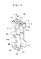
- FIG. 2 is a perspective view of the protecting cap;
- FIG. 3 is a partially sectional view of the connector and the protecting cap attached to the connector;
- FIG. 4 is a perspective view of a second embodiment of the connector;
- FIG. 5 is a perspective view of the protecting cap;
- FIG. 6 is a partially sectional view of the connector and the protecting cap attached to the connector;
- FIGS. 7A, 7B and 7C are schematic side views of a modified form of the connector and the protecting cap;
- FIG. 8 is a schematically sectional view of a conventional connector and protecting cap; and
- FIG. 9 is a partially sectional view of the conventional connector with the protecting cap being attached thereto for explaining the mounting of the connector on a panel
- A first embodiment of the present invention will be described with reference to FIGS. 1 to 3. In the first embodiment, the invention is applied to a male connector used in the automobile. The panel-mounted connector 10 comprises a generally
rectangular body 20 holding therein a plurality of male terminals (not shown) and generallycylindrical hood 30 projecting forward of theconnector body 20 and surrounding portions of the male terminals fitted with female terminals (not shown). The size of thehood 30 is set so that the female terminals can be inserted thereinto. The female terminals are inserted into thehood 30 to be connected to the respective male terminals. - The
hood 30 has a rectangular section with rounded corners. Thehood 30 has an open end and aflange 31 formed on the outer periphery of the open end thereof except for the central portions of the upper and lower walls. Four plate-like positioning ribs 32 extend outward from the respective corners of thehood 30. Two plate-like locking arms 33 are formed on the central portions of the upper and lower walls of thehood 30 where theflange 31 is not formed. The lockingarms 33 project slightly forward relative to thepositioning ribs 32. Each lockingarm 33 has anengagement protrusion 34 formed on the outer peripheral surface of its distal end. Eachengagement protrusion 34 includes an inclined surface 34a gradually projecting outward from the distal end side as it goes rearward and avertical wall surface 34b formed on the termination of the inclined surface 34a. The distance between thevertical wall surface 34b and theflange 31 is approximately equal to the thickness of a panel P. Thehood 30 is cut so that the lockingarms 33 flexes readily. - A protecting
cap 40 is attached to thehood 30 of the connector 10 to close the open end, thereby protecting the male terminals held in thehood 30. The protectingcap 40 comprises alid portion 41 closing thehood 30. The sectional configuration of the attached end of thelid portion 41 is the same as that of the open end of thehood 30. The protectingcap 40 is generally formed into the shape of a dome with a tapered forward end. More specifically, the protectingcap 40 has upper and lower inclined faces 41 a and right-hand and left-hand inclined faces 41 b such that thecap 40 has generally trapezoidal transverse and longitudinal sections. The upper and lower inclined faces 41 a of thelid 41 are so formed as to be substantially aligned with the inclined faces 34a of theengagement protrusions 34 formed on the distal ends of the lockingarms 33, respectively, when the protectingcap 40 has been attached to the connector 10, as shown in FIG. 3. The protectingcap 40 is designed not to project outward of thepositioning ribs 32 and to pass through the mounting hole W of the panel P. - The protecting
cap 40 has four plate-like mountingribs 42 formed to project from four corners of the side thereof from which thecap 40 is attached to thehood 30, respectively. The mountingribs 42 are inserted along the inner surfaces of therespective positioning ribs 32. The protectingcap 40 further has two plate-likedeformation preventing portions 43 formed on the central portions of the respective upper and lower walls. Eachdeformation preventing portion 43 projects toward the side of thehood 30 as in the mountingribs 42. Thedeformation preventing portions 43 correspond to the respective lockingarms 33. Arib 45 is formed between thedeformation preventing portions 43 on the inner surface of the protectingcap 40 so that thedeformation preventing portions 43 are reinforced. - The distal end of each
deformation preventing portion 43 is not reinforced by therib 45 so as to have elasticity. Eachdeformation preventing portion 43 has anengagement protrusion 44 formed on the outer peripheral side of the distal end thereof. Eachengagement protrusion 44 includes aninclined face 44a projecting outward from the side of thehood 30 toward the distal end thereof and avertical wall face 44b formed on the termination of theinclined face 44a. Theengagement protrusion 44 is formed on each lockingarm 33 to be located at the central portion in the direction of the width thereof. Thehood 30 has twoengagement grooves 35 each extending inwardly from the root of each lockingarm 33 so that eachengagement groove 35 is contiguous to the inside and outside of thehood 30. Theengagement grooves 35 are disposed to correspond to therespective engagement protrusions 44. Since theengagement protrusions 44 engages therespective engagement grooves 35 inside thehood 30, the height of eachengagement protrusion 44 is set so that the distance between the tops of theengagement protrusions 44 is larger than the distance between the inner faces of the lockingarms 33. Each lockingarm 33 has aguide groove 36 formed in the distal end of the inner face thereof along an insertion path of theengagement protrusion 44. Eachguide groove 36 becomes shallower as it goes inward. A pair of engagement members are composed of the mountingribs 42, the deformation preventing portions and the like, respectively, - In attachment of the
cap 40 to the connector 10, theribs 45 are inserted along the inner faces of thepositioning ribs 32 of thehood 30 respectively. In this case, theengagement protrusions 44 of thedeformation preventing portions 43 are first inserted into therespective guide grooves 36 so that thecap 40 is positioned. Then, thecap 40 is gradually inserted into thehood 30. When eachengagement protrusion 44 is inserted with its positional shift in the direction of the width restricted by theguide groove 36, the mountingribs 45 are inserted along the inner faces of therespective positioning ribs 32. - The positional shift of the
engagement protrusions 43 is not caused when theribs 45 have been inserted in the inner faces of therespective positioning ribs 32. Then, theguide grooves 36 are not necessary, and eachengagement protrusion 44 goes over the inclined face of theguide groove 36 to be gradually pushed inward such that the distal end of each lockingarm 33 flexes inward. When thecap 40 is pushed in such that theribs 45 have been completely inserted in thehood 30, thevertical wall face 44b of eachengagement protrusion 44 is located at the distal end of theengagement groove 35 of thehood 30, as shown in FIG. 3. Eachdeformation preventing portion 43 then returns to its normal shape such that theengagement protrusions 43 invade theengagement grooves 35, engaging them, respectively. - The locking
arms 33 are located outside the respectivedeformation preventing portions 42 when the protectingcap 40 has been attached to the connector 10, as described above. Accordingly, each lockingarm 33 abuts against thedeformation preventing portion 43 when something strikes against the outer face of each locking arm during the transportation and a force acts on each lockingarm 33 to cause it to be pushed inward. However, the lockingarms 33 are held by thedeformation preventing portions 44 from inside respectively such that each locking arm is prevented form flexing to such a degree that it cannot return to its normal shape. - Two plate-shaped
convex portions 46 are formed on each of upper and lower distal end corners of the protectingcap 40 so as to project outward. The height of eachconvex portion 46 is determined so that eachconvex portion 46 does not project from the outer periphery of thecap 40. Eachconvex portion 46 is formed to be inclined rearward. Since eachconvex portion 46 is formed into the shape of a plate, it has elasticity so as to deform forward and rearward. Since eachconvex portion 46 is inclined rearward, a force applied to it to deform rearward is smaller than a force applied to it to deform forward. - The protecting
cap 40 is designed not to project outward of thepositioning ribs 32 and to pass through the mounting hole W of the panel P, as described above. Furthermore, since the distal end of thecap 40 is tapered, the distal end is sufficiently smaller than the mounting hole W such that it can be inserted into the mounting hole W readily. For example, holding theconnector body 20 and abutting the distal end of thecap 40 against the panel P, the worker needs to fumble for the hole W when the hole cannot be viewed. Since the conventional protecting cap has the distal end whose configuration is substantially the same as that of the mounting hole, the protecting cap cannot be inserted into the mounting hole until the center position and the relative angle of the protecting cap correspond to those of the mounting hole. However, since the distal end of the protectingcap 40 is tapered in the present embodiment, the distal end of thecap 40 can be easily inserted into the mounting hole W even when there is a positional shift between the cap and the hole. When the distal end of thecap 40 has evaded the hole W, the inclined faces 41 a and 41 b slide on the edge of the mounting hole W as thecap 40 is further pushed into the hole. Thus, the positional shift is gradually corrected and the cap is accurately positioned. - The
convex portions 46 abut against the edge of the mounting hole when the distal end of thecap 40 is inserted into the hole. However, since theconvex portions 46 are formed partially on the distal end of the cap, the inserting work is not interrupted. Furthermore, since eachconvex portion 46 has elasticity, it readily flexes even if it abuts against the edge of the mounting hole W. In particular, since eachconvex portion 46 can readily flex rearward, it does not cause any problem when the worker fumbles the mounting hole W and pushes the cap into the hole. - There is a case where the worker's hand slips on the panel P immediately after insertion of the distal end of the cap into the mounting hole W and the connector 10 happens to fall of from the worker's hand. Furthermore, the connector 10 needs to be passed from one hand to the other depending upon the condition of the harness connected to the connector. In these cases, the protecting cap easily falls out from the connector because of its weight. In particular, the protecting cap such as the
cap 40 having the tapered distal end easily falls out from the connector. However, Since theconvex portions 46 are hooked on the edge of the mounting hole W, the falling off can be prevented. Since eachconvex portion 46 projects to be inclined rearward, it needs to flex sufficiently forward so that the protecting cap falls off from the connector. - Upon insertion of the distal end of the protecting cap, the connector 10 is gradually pushed into the mounting hole, so that any one of the inclined faces 41 a, 41 b of the
lid portion 41 slides on the edge of the mounting hole, thereby guiding the protecting cap to its normal position as the connector is inserted into the mounting hole. Then, when the inclined faces 34a of theengagement protrusions 34 of the lockingarms 33 abut against the edge of the mounting hole W, the edge of the mounting hole causes the lockingarms 33 to flex inward. Since the upper and lower inclined faces 41 a of thelid portion 41 are aligned with the inclined faces 34a of theengagement protrusions 34 respectively, the lockingarms 33 do not abut against the edge of the mounting hole W but smoothly slide thereon. When the lockingarms 33 starts flexing inward, thepositioning ribs 32 invade the mounting hole W to abut against the edge of the hole from inside, thereby positioning the connector 10. When the connector 10 is inserted into the mounting hole W until theflange 31 abuts against the panel P, the vertical wall faces 34b of theengagement protrusions 34 are located at the opposite side of the panel P. Then, each lockingarm 33 having flexed return to its normal shape. Consequently, the panel P is held between theengagement protrusions 34 and theflange 31 and the lockingarms 33 engage the panel P. - The protecting
cap 40 is detached from the connector when the female connector is connected to the male connector. Since the inclined side faces 41 b of thecap 40 are tape red, it is difficult to pull the cap out of the connector. However, since theconvex portions 46 are formed on the corners of the upper and lower inclined faces 41 b. thecap 40 can be held and pulled out easily when these convex portions afford hold for the fingers. - FIGS. 4 to 6 illustrate a second embodiment of the invention. Although the deformation preventing portions also serve as the engagement members in the forgoing embodiment, the engagement members are formed on the mounting ribs formed on the side faces of the cap respectively.
- The
flange 131 is formed on the whole outer periphery of the open end of thehood 130. The plate-like positioning ribs 132 project forward from the corners of thehood 130. Thehood 130 has twoarm holding chambers 133 formed in the upper and lower walls to extend longitudinally through the walls respectively. Eacharm holding chamber 133 is inwardly bent such that the front end of the inner wall is lower than the outer wall thereof. Eacharm holding chamber 133 has an engagement protrusion 133a formed on the rear portion of the inner wall to project outward. - Each locking
arm 134 is formed by bending a band-shaped metal plate. The front end of each lockingarm 134 is folded rearward such that theengagement protrusion portion 134a is formed. The rear end of each lockingarm 134 is folded forward such that anengagement hole 134b into which the engagement protrusion 133a can be inserted is formed. - Each locking
arm 134 is inserted into thearm holding chamber 133 from the end on which theengagement hole 134b is formed, and the engagement protrusion 133a is engaged with theengagement hole 134b, whereby each lockingarm 134 is held in thearm holding chamber 133, as shown in FIG. 6. Since the front end of the inner wall of eacharm holding chamber 133 is lowered inward relative to the outer wall thereof, the distal end of each lockingarm 134 on which theengagement protrusion 134a is formed can readily flex into thehood 130. When the lockingarms 134 have been held in the respectivearm holding chambers 133, theengagement protrusions 134a project outward and the edge of the mounting hole W of the panel P is held between theengagement protrusions 134a and theflange 131, whereby theengagement protrusions 134a engage the edge of the hole W. - A part of the inner side wall of the
hood 130 is inwardly raised so that afemale screw section 135 with the female screw projecting toward the open end is provided.Engagement grooves 136 andribs 137 guiding the female connector are formed in the upper and lower portions of each of the right-hand and left-hand side walls. Eachengagement groove 136 is contiguous to the inside and outside of thehood 130. - The protecting
cap 140 includes thelid portion 141 formed into the shape of a dome so as to close the open end of thehood 130. Thelid portion 141 includes the upper and lowerinclined faces 141 a and right-hand and left-hand inclined faces 141b such that thelid portion 141 has generally trapezoidal transverse and longitudinal sections. The protectingcap 140 is designed not to project outward of thepositioning ribs 32 and to pass through the mounting hole W of the panel P. Furthermore, the upper and lowerinclined faces 141 a of the protectingcap 140 are located at the outer peripheral side relative to the distal ends of the lockingarms 134. - The
cap 140 has positioningribs 142 each projecting from an opening of thelid portion 141 along the inner peripheral face of thehood 130. Central portions of upper and lower walls of eachpositioning rib 142 are notched forward and the width of each notched portion is slightly larger than that of thelocking arm 134. Unnotched portions of the upper and lower walls serve as thedeformation preventing portions 143 respectively. Therib 144 reinforcing bothdeformation preventing portions 143 are formed to connect between thedeformation preventing portions 143. A part of eachpositioning rib 142 is cut off so as not to interfere with the projecting portion formed on the side wall of thehood 130. Thecap 140 has on the outer peripheral face of its distal end theengagement protrusions 145 formed to correspond to therespective engagement grooves 136 formed in thehood 130. A pair of engagement members are composed of thepositioning ribs 142 and theengagement protrusions 145, respectively. - In attachment of the protecting
cap 140 to theconnector 110, thecap 140 is inserted into thehood 130 from its side of thepositioning ribs 142. When thepositioning ribs 142 have been completely inserted in thehood 130, theengagement protrusions 145 invade therespective engagement grooves 136, thereby engaging them. FIG. 6 illustrates the state that theengagement protrusions 145 are in engagement with therespective engagement grooves 136. In this state, eachdeformation preventing portion 143 is inserted in the inside of the distal end of thelocking arm 134 with a small gap therebetween. In the state that the protectingcap 140 has been inserted in thehood 130, each lockingarm 134 abuts against thedeformation preventing portion 143 located inside when something strikes against the outer face of each lockingarm 134 during the transportation such that a force pushing each lockingarm 134 inward is applied thereto. However, since the lockingarms 134 are held by thedeformation preventing portions 143 located inside, each lockingarm 134 can be prevented from flexing to such a degree that it cannot return to its normal shape. - The distal end of each locking
arm 134 is slightly away from the outer face of thedeformation preventing protion 143, and eachpositioning rib 142 is notched by the length corresponding to the width of thelocking arm 134. Accordingly, each lockingarm 134 can flex inward until its distal end abuts against thedeformation preventing portion 143. Furthermore, the protectingcap 140 does not project outside thepositioning ribs 132 of theconnector 110. Accordingly, theconnector 110 can be inserted into the mounting hole W of the panel P with the protectingcap 140 being attached there to. Furthermore, since the distal end of thecap 140 is tapered, the distal end is sufficiently smaller than the mounting hole W such that thecap 140 can be readily inserted into theconnector 110. In particular since the distal ends of the lockingarms 134 are not located outside the upper and lowerinclined faces cap 140, theengagement protrusions 134a start smoothly contacting the edge of the mounting hole W when theinclined faces arms 134 can flex inward. - Since the distal end of the protecting
cap 140 is tapered, the distal end of thecap 140 can be easily inserted into the mounting hole W even when there is a positional shift between the cap and the hole. When the distal end of thecap 140 has evaded the hole W, the inclined faces 141 a and 141 b slide on the edge of the mounting hole W as thecap 140 is further pushed into the hole. Thus, the positional shift is gradually corrected and the cap is accurately positioned. - Upon insertion of the distal end of the protecting cap, the
connector 110 is gradually pushed into the mounting hole, so that any one of the inclined faces 141 a, 141 b slides on the edge of the mounting hole, thereby guiding the protecting cap to its normal position as the connector is inserted into the mounting hole. When the lockingarms 133 starts flexing inward, thepositioning ribs 132 invade the mounting hole W to abut against the edge of the hole from inside, thereby positioning theconnector 110. When theconnector 110 is inserted into the mounting hole W until theflange 131 abuts against the panel P, theengagement protrusions 134a are located at the opposite side of the panel P. Then, each lockingarm 133 having flexed return to its normal shape, as shown in FIG. 6. Consequently, the panel P is held between theengagement protrusions 134 and theflange 131, and the lockingarms 33 engage the panel P. - Although the straight inclined faces are formed by the entire faces of the side walls of the lid portion in the foregoing embodiments, only the distal end corners of the lid portion may be formed into the inclined faces, as shown in FIG. 7A. Furthermore, each inclined face may be curved as shown in FIG. 7B. Additionally, a rib may be provided on the distal end of the lid portion so as to project and end faces of the rib may be inclined as shown in FIG. 7C.
- The foregoing disclosure and drawings are merely illustrative of the principles of the present invention and are not to be construed in a limiting sense. Various changes and modifications will become apparent to those of ordinary skill in the art. All such changes and modifications are seen to fall within the true spirit and scope of the invention as defined by the appended claims.
Claims (7)
Applications Claiming Priority (2)
| Application Number | Priority Date | Filing Date | Title |
|---|---|---|---|
| JP1993016910U JP2567946Y2 (en) | 1993-03-11 | 1993-03-11 | Protection cap for panel mounting connector |
| JP16910/93U | 1993-03-11 |
Publications (3)
| Publication Number | Publication Date |
|---|---|
| EP0615314A2 true EP0615314A2 (en) | 1994-09-14 |
| EP0615314A3 EP0615314A3 (en) | 1995-08-30 |
| EP0615314B1 EP0615314B1 (en) | 1998-10-28 |
Family
ID=11929302
Family Applications (1)
| Application Number | Title | Priority Date | Filing Date |
|---|---|---|---|
| EP94103697A Expired - Lifetime EP0615314B1 (en) | 1993-03-11 | 1994-03-10 | Combination of a panel mountable electrical connector with a protecting cap |
Country Status (4)
| Country | Link |
|---|---|
| US (1) | US5480312A (en) |
| EP (1) | EP0615314B1 (en) |
| JP (1) | JP2567946Y2 (en) |
| DE (1) | DE69414156T2 (en) |
Cited By (1)
| Publication number | Priority date | Publication date | Assignee | Title |
|---|---|---|---|---|
| EP1732175A2 (en) * | 2005-06-08 | 2006-12-13 | Lapp Engineering & Co | Angular connector housing with cover |
Families Citing this family (21)
| Publication number | Priority date | Publication date | Assignee | Title |
|---|---|---|---|---|
| DE4313285C1 (en) * | 1993-04-23 | 1994-04-21 | Hella Kg Hueck & Co | Housing cover for e.g. relay housing - has grooves of different types in region of two end-sections of cover plate for aiding orientation and extraction. |
| US5746611A (en) * | 1996-07-15 | 1998-05-05 | The Whitaker Corporation | Electrical connector seal cap assembly |
| US6095852A (en) * | 1998-12-17 | 2000-08-01 | Yazaki North America, Inc. | Connector bracket wire shield with connector retention arms |
| US6454581B1 (en) * | 2000-12-28 | 2002-09-24 | Spx Corporation | Plug for covering a plurality of openings of an electronic device |
| US7165372B1 (en) * | 2004-12-10 | 2007-01-23 | Skulsky Bryan S | Pergola end cap method |
| TW529818U (en) * | 2002-05-24 | 2003-04-21 | Hon Hai Prec Ind Co Ltd | Connector protecting device |
| US7217146B2 (en) * | 2004-12-17 | 2007-05-15 | Scientific-Atlanta, Inc. | Connector insert for preventing contamination |
| JP4520315B2 (en) * | 2005-01-21 | 2010-08-04 | タイコエレクトロニクスジャパン合同会社 | Wire cover for connector |
| US7408469B2 (en) * | 2005-06-07 | 2008-08-05 | B&G Plastics, Inc. | Security device for electrical cord |
| TWM299385U (en) * | 2006-01-20 | 2006-10-11 | Hon Hai Prec Ind Co Ltd | Electrical connector |
| WO2008073169A2 (en) * | 2006-08-31 | 2008-06-19 | The Trustees Of The University Of Pennsylvania | Methods, compositions and kits comprising attenuated anthrax vaccines and methods of delivery |
| US20120214335A1 (en) * | 2009-03-30 | 2012-08-23 | John Mezzalingua Associates, Inc. | Cover for cable connectors |
| US8853542B2 (en) | 2009-03-30 | 2014-10-07 | John Mezzalingua Associates, LLC | Collar for sealingly engaging a cover for cable connectors |
| US8764480B2 (en) | 2010-04-14 | 2014-07-01 | John Mezzalingua Associates, LLP | Cover for cable connectors |
| DE102011087615A1 (en) * | 2011-12-02 | 2013-06-06 | Tyco Electronics Amp Gmbh | Contactor protection cap and electrical, electronic and / or optical device, device, device |
| USD805039S1 (en) * | 2015-01-29 | 2017-12-12 | Layer Zero Power Systems, Inc. | Cover |
| JP6324364B2 (en) * | 2015-12-11 | 2018-05-16 | 矢崎総業株式会社 | Connector wire cover |
| JP1604551S (en) * | 2017-07-20 | 2018-05-21 | ||
| JP1604074S (en) * | 2017-07-20 | 2018-05-21 | ||
| JP6916995B2 (en) * | 2018-01-31 | 2021-08-11 | 住友電装株式会社 | Wire cover and connector |
| US11458496B2 (en) * | 2020-11-07 | 2022-10-04 | Harry S. Audell | Foldable disposable protective cover for round gang boxes and lighting housings mounted in walls and ceilings of residential and commercial buildings |
Citations (3)
| Publication number | Priority date | Publication date | Assignee | Title |
|---|---|---|---|---|
| US4235502A (en) * | 1979-04-23 | 1980-11-25 | Amp Incorporated | Mounting means for mounting a connector in a panel |
| EP0323064A2 (en) * | 1987-12-28 | 1989-07-05 | Honda Giken Kogyo Kabushiki Kaisha | Simplified waterproof electrical connector |
| US5139431A (en) * | 1990-07-09 | 1992-08-18 | Yazaki Corporation | Waterproofing device for screw-tightened connectors |
Family Cites Families (10)
| Publication number | Priority date | Publication date | Assignee | Title |
|---|---|---|---|---|
| US2987690A (en) * | 1959-05-11 | 1961-06-06 | Victor D Marbais | Electrical wall outlet cover and guard |
| JPS54116694A (en) * | 1978-03-03 | 1979-09-11 | Yazaki Corp | Waterrproof connector |
| US4742541A (en) * | 1983-10-25 | 1988-05-03 | Northern Telecom Limited | Telecommunications interface with protector modules |
| US4541538A (en) * | 1984-04-16 | 1985-09-17 | General Electric Company | Wiring device covers |
| US5003128A (en) * | 1988-11-08 | 1991-03-26 | Yvan Grondin | Electrical switch and outlets protecting cover for painting |
| JPH0355263A (en) * | 1989-07-13 | 1991-03-11 | Fuji Xerox Co Ltd | Ink droplet charge control system for charge control type ink jet printer |
| FR2656746B1 (en) * | 1989-12-28 | 1992-04-03 | Telemecanique | PROTECTIVE HOUSING FOR ELECTRICAL DISTRIBUTION BARS. |
| JPH0587844A (en) * | 1991-09-26 | 1993-04-06 | Toshiba Corp | Power source synchronizer pll controller |
| JPH0744079Y2 (en) * | 1991-12-09 | 1995-10-09 | モレックス インコーポレーテッド | Surface mount connector auto mount cover |
| US5285014A (en) * | 1991-12-11 | 1994-02-08 | Gayland Gilchrist | Paint shield for electrical outlets and switches |
-
1993
- 1993-03-11 JP JP1993016910U patent/JP2567946Y2/en not_active Expired - Lifetime
-
1994
- 1994-03-10 EP EP94103697A patent/EP0615314B1/en not_active Expired - Lifetime
- 1994-03-10 DE DE69414156T patent/DE69414156T2/en not_active Expired - Lifetime
- 1994-03-10 US US08/208,278 patent/US5480312A/en not_active Expired - Lifetime
Patent Citations (3)
| Publication number | Priority date | Publication date | Assignee | Title |
|---|---|---|---|---|
| US4235502A (en) * | 1979-04-23 | 1980-11-25 | Amp Incorporated | Mounting means for mounting a connector in a panel |
| EP0323064A2 (en) * | 1987-12-28 | 1989-07-05 | Honda Giken Kogyo Kabushiki Kaisha | Simplified waterproof electrical connector |
| US5139431A (en) * | 1990-07-09 | 1992-08-18 | Yazaki Corporation | Waterproofing device for screw-tightened connectors |
Cited By (2)
| Publication number | Priority date | Publication date | Assignee | Title |
|---|---|---|---|---|
| EP1732175A2 (en) * | 2005-06-08 | 2006-12-13 | Lapp Engineering & Co | Angular connector housing with cover |
| EP1732175A3 (en) * | 2005-06-08 | 2007-02-28 | Lapp Engineering & Co | Angular connector housing with cover |
Also Published As
| Publication number | Publication date |
|---|---|
| DE69414156T2 (en) | 1999-07-01 |
| EP0615314A3 (en) | 1995-08-30 |
| DE69414156D1 (en) | 1998-12-03 |
| JP2567946Y2 (en) | 1998-04-08 |
| US5480312A (en) | 1996-01-02 |
| JPH0670175U (en) | 1994-09-30 |
| EP0615314B1 (en) | 1998-10-28 |
Similar Documents
| Publication | Publication Date | Title |
|---|---|---|
| EP0615314A2 (en) | Protecting cap for panelmounted electrical connector | |
| US6165026A (en) | Terminal | |
| EP1936749B1 (en) | A terminal fitting, a connector and a forming method | |
| US5769650A (en) | Connector and cover therefor | |
| EP0615315B1 (en) | Panel-mounted electrical connector | |
| EP0676828A2 (en) | Connector | |
| US7572142B2 (en) | Connector | |
| US10340618B1 (en) | Electrical terminal housing with releasable terminal locks | |
| JPH08321343A (en) | Female terminal fitting | |
| EP0902504B1 (en) | Front holder-incorporating connector | |
| EP0940883B1 (en) | Connector retaining construction | |
| KR100326219B1 (en) | Electrical connector with terminal position assurance device | |
| JP3405425B2 (en) | Board connector | |
| EP0981184B1 (en) | Connector housing with hinged retainer | |
| US5277603A (en) | Electric connector | |
| JPH11204201A (en) | Wrench preventive structure for terminal | |
| US5344348A (en) | Electrical terminal | |
| US7033205B2 (en) | Connector with a collision preventing projection | |
| KR0149884B1 (en) | Fitting structure of box type electrical component | |
| US5520556A (en) | Female terminal | |
| US5984701A (en) | Low insertion force connector | |
| US5498177A (en) | Structure for thin-walled hinge | |
| US5613878A (en) | Reverse insertion preventing connector | |
| EP0611867B1 (en) | Panel-fixed type connector | |
| JP3275941B2 (en) | Terminal locking structure of fuse box |
Legal Events
| Date | Code | Title | Description |
|---|---|---|---|
| PUAI | Public reference made under article 153(3) epc to a published international application that has entered the european phase |
Free format text: ORIGINAL CODE: 0009012 |
|
| AK | Designated contracting states |
Kind code of ref document: A2 Designated state(s): DE GB |
|
| PUAL | Search report despatched |
Free format text: ORIGINAL CODE: 0009013 |
|
| AK | Designated contracting states |
Kind code of ref document: A3 Designated state(s): DE GB |
|
| 17P | Request for examination filed |
Effective date: 19951102 |
|
| 17Q | First examination report despatched |
Effective date: 19970124 |
|
| GRAG | Despatch of communication of intention to grant |
Free format text: ORIGINAL CODE: EPIDOS AGRA |
|
| GRAG | Despatch of communication of intention to grant |
Free format text: ORIGINAL CODE: EPIDOS AGRA |
|
| GRAH | Despatch of communication of intention to grant a patent |
Free format text: ORIGINAL CODE: EPIDOS IGRA |
|
| GRAH | Despatch of communication of intention to grant a patent |
Free format text: ORIGINAL CODE: EPIDOS IGRA |
|
| GRAH | Despatch of communication of intention to grant a patent |
Free format text: ORIGINAL CODE: EPIDOS IGRA |
|
| GRAA | (expected) grant |
Free format text: ORIGINAL CODE: 0009210 |
|
| AK | Designated contracting states |
Kind code of ref document: B1 Designated state(s): DE GB |
|
| REF | Corresponds to: |
Ref document number: 69414156 Country of ref document: DE Date of ref document: 19981203 |
|
| PLBE | No opposition filed within time limit |
Free format text: ORIGINAL CODE: 0009261 |
|
| STAA | Information on the status of an ep patent application or granted ep patent |
Free format text: STATUS: NO OPPOSITION FILED WITHIN TIME LIMIT |
|
| 26N | No opposition filed | ||
| REG | Reference to a national code |
Ref country code: GB Ref legal event code: IF02 |
|
| PGFP | Annual fee paid to national office [announced via postgrant information from national office to epo] |
Ref country code: GB Payment date: 20020313 Year of fee payment: 9 |
|
| PG25 | Lapsed in a contracting state [announced via postgrant information from national office to epo] |
Ref country code: GB Free format text: LAPSE BECAUSE OF NON-PAYMENT OF DUE FEES Effective date: 20030310 |
|
| GBPC | Gb: european patent ceased through non-payment of renewal fee |
Effective date: 20030310 |
|
| PGFP | Annual fee paid to national office [announced via postgrant information from national office to epo] |
Ref country code: DE Payment date: 20110302 Year of fee payment: 18 |
|
| REG | Reference to a national code |
Ref country code: DE Ref legal event code: R119 Ref document number: 69414156 Country of ref document: DE Effective date: 20121002 |
|
| PG25 | Lapsed in a contracting state [announced via postgrant information from national office to epo] |
Ref country code: DE Free format text: LAPSE BECAUSE OF NON-PAYMENT OF DUE FEES Effective date: 20121002 |