WO2014199574A1 - 車載表示装置およびプログラム製品 - Google Patents
車載表示装置およびプログラム製品 Download PDFInfo
- Publication number
- WO2014199574A1 WO2014199574A1 PCT/JP2014/002741 JP2014002741W WO2014199574A1 WO 2014199574 A1 WO2014199574 A1 WO 2014199574A1 JP 2014002741 W JP2014002741 W JP 2014002741W WO 2014199574 A1 WO2014199574 A1 WO 2014199574A1
- Authority
- WO
- WIPO (PCT)
- Prior art keywords
- obstacle
- image
- vehicle
- driver
- display
- Prior art date
Links
- 230000007704 transition Effects 0.000 claims description 4
- 239000004973 liquid crystal related substance Substances 0.000 description 16
- 238000000034 method Methods 0.000 description 12
- 230000008569 process Effects 0.000 description 9
- 230000005540 biological transmission Effects 0.000 description 5
- 238000004364 calculation method Methods 0.000 description 3
- 230000006870 function Effects 0.000 description 3
- 238000006243 chemical reaction Methods 0.000 description 2
- 238000010586 diagram Methods 0.000 description 2
- 230000000694 effects Effects 0.000 description 2
- 230000004048 modification Effects 0.000 description 2
- 238000012986 modification Methods 0.000 description 2
- 230000009471 action Effects 0.000 description 1
- 230000008859 change Effects 0.000 description 1
- 239000003086 colorant Substances 0.000 description 1
- 238000004590 computer program Methods 0.000 description 1
- 230000003247 decreasing effect Effects 0.000 description 1
- 230000003111 delayed effect Effects 0.000 description 1
- 239000000284 extract Substances 0.000 description 1
- 238000000605 extraction Methods 0.000 description 1
- 238000003384 imaging method Methods 0.000 description 1
- 230000007246 mechanism Effects 0.000 description 1
- 239000004065 semiconductor Substances 0.000 description 1
- 230000000007 visual effect Effects 0.000 description 1
Images
Classifications
-
- G—PHYSICS
- G02—OPTICS
- G02B—OPTICAL ELEMENTS, SYSTEMS OR APPARATUS
- G02B27/00—Optical systems or apparatus not provided for by any of the groups G02B1/00 - G02B26/00, G02B30/00
- G02B27/01—Head-up displays
- G02B27/0101—Head-up displays characterised by optical features
-
- B—PERFORMING OPERATIONS; TRANSPORTING
- B60—VEHICLES IN GENERAL
- B60K—ARRANGEMENT OR MOUNTING OF PROPULSION UNITS OR OF TRANSMISSIONS IN VEHICLES; ARRANGEMENT OR MOUNTING OF PLURAL DIVERSE PRIME-MOVERS IN VEHICLES; AUXILIARY DRIVES FOR VEHICLES; INSTRUMENTATION OR DASHBOARDS FOR VEHICLES; ARRANGEMENTS IN CONNECTION WITH COOLING, AIR INTAKE, GAS EXHAUST OR FUEL SUPPLY OF PROPULSION UNITS IN VEHICLES
- B60K35/00—Instruments specially adapted for vehicles; Arrangement of instruments in or on vehicles
- B60K35/20—Output arrangements, i.e. from vehicle to user, associated with vehicle functions or specially adapted therefor
- B60K35/21—Output arrangements, i.e. from vehicle to user, associated with vehicle functions or specially adapted therefor using visual output, e.g. blinking lights or matrix displays
- B60K35/23—Head-up displays [HUD]
-
- B—PERFORMING OPERATIONS; TRANSPORTING
- B60—VEHICLES IN GENERAL
- B60K—ARRANGEMENT OR MOUNTING OF PROPULSION UNITS OR OF TRANSMISSIONS IN VEHICLES; ARRANGEMENT OR MOUNTING OF PLURAL DIVERSE PRIME-MOVERS IN VEHICLES; AUXILIARY DRIVES FOR VEHICLES; INSTRUMENTATION OR DASHBOARDS FOR VEHICLES; ARRANGEMENTS IN CONNECTION WITH COOLING, AIR INTAKE, GAS EXHAUST OR FUEL SUPPLY OF PROPULSION UNITS IN VEHICLES
- B60K35/00—Instruments specially adapted for vehicles; Arrangement of instruments in or on vehicles
- B60K35/20—Output arrangements, i.e. from vehicle to user, associated with vehicle functions or specially adapted therefor
- B60K35/28—Output arrangements, i.e. from vehicle to user, associated with vehicle functions or specially adapted therefor characterised by the type of the output information, e.g. video entertainment or vehicle dynamics information; characterised by the purpose of the output information, e.g. for attracting the attention of the driver
-
- B—PERFORMING OPERATIONS; TRANSPORTING
- B60—VEHICLES IN GENERAL
- B60R—VEHICLES, VEHICLE FITTINGS, OR VEHICLE PARTS, NOT OTHERWISE PROVIDED FOR
- B60R11/00—Arrangements for holding or mounting articles, not otherwise provided for
- B60R11/04—Mounting of cameras operative during drive; Arrangement of controls thereof relative to the vehicle
-
- G—PHYSICS
- G02—OPTICS
- G02B—OPTICAL ELEMENTS, SYSTEMS OR APPARATUS
- G02B27/00—Optical systems or apparatus not provided for by any of the groups G02B1/00 - G02B26/00, G02B30/00
- G02B27/01—Head-up displays
-
- G—PHYSICS
- G06—COMPUTING; CALCULATING OR COUNTING
- G06T—IMAGE DATA PROCESSING OR GENERATION, IN GENERAL
- G06T7/00—Image analysis
- G06T7/50—Depth or shape recovery
-
- G—PHYSICS
- G06—COMPUTING; CALCULATING OR COUNTING
- G06T—IMAGE DATA PROCESSING OR GENERATION, IN GENERAL
- G06T7/00—Image analysis
- G06T7/70—Determining position or orientation of objects or cameras
-
- G—PHYSICS
- G06—COMPUTING; CALCULATING OR COUNTING
- G06V—IMAGE OR VIDEO RECOGNITION OR UNDERSTANDING
- G06V20/00—Scenes; Scene-specific elements
- G06V20/50—Context or environment of the image
- G06V20/56—Context or environment of the image exterior to a vehicle by using sensors mounted on the vehicle
- G06V20/58—Recognition of moving objects or obstacles, e.g. vehicles or pedestrians; Recognition of traffic objects, e.g. traffic signs, traffic lights or roads
-
- G—PHYSICS
- G08—SIGNALLING
- G08G—TRAFFIC CONTROL SYSTEMS
- G08G1/00—Traffic control systems for road vehicles
- G08G1/16—Anti-collision systems
- G08G1/166—Anti-collision systems for active traffic, e.g. moving vehicles, pedestrians, bikes
-
- B—PERFORMING OPERATIONS; TRANSPORTING
- B60—VEHICLES IN GENERAL
- B60K—ARRANGEMENT OR MOUNTING OF PROPULSION UNITS OR OF TRANSMISSIONS IN VEHICLES; ARRANGEMENT OR MOUNTING OF PLURAL DIVERSE PRIME-MOVERS IN VEHICLES; AUXILIARY DRIVES FOR VEHICLES; INSTRUMENTATION OR DASHBOARDS FOR VEHICLES; ARRANGEMENTS IN CONNECTION WITH COOLING, AIR INTAKE, GAS EXHAUST OR FUEL SUPPLY OF PROPULSION UNITS IN VEHICLES
- B60K2360/00—Indexing scheme associated with groups B60K35/00 or B60K37/00 relating to details of instruments or dashboards
- B60K2360/16—Type of output information
- B60K2360/177—Augmented reality
-
- B—PERFORMING OPERATIONS; TRANSPORTING
- B60—VEHICLES IN GENERAL
- B60K—ARRANGEMENT OR MOUNTING OF PROPULSION UNITS OR OF TRANSMISSIONS IN VEHICLES; ARRANGEMENT OR MOUNTING OF PLURAL DIVERSE PRIME-MOVERS IN VEHICLES; AUXILIARY DRIVES FOR VEHICLES; INSTRUMENTATION OR DASHBOARDS FOR VEHICLES; ARRANGEMENTS IN CONNECTION WITH COOLING, AIR INTAKE, GAS EXHAUST OR FUEL SUPPLY OF PROPULSION UNITS IN VEHICLES
- B60K2360/00—Indexing scheme associated with groups B60K35/00 or B60K37/00 relating to details of instruments or dashboards
- B60K2360/16—Type of output information
- B60K2360/178—Warnings
-
- B—PERFORMING OPERATIONS; TRANSPORTING
- B60—VEHICLES IN GENERAL
- B60K—ARRANGEMENT OR MOUNTING OF PROPULSION UNITS OR OF TRANSMISSIONS IN VEHICLES; ARRANGEMENT OR MOUNTING OF PLURAL DIVERSE PRIME-MOVERS IN VEHICLES; AUXILIARY DRIVES FOR VEHICLES; INSTRUMENTATION OR DASHBOARDS FOR VEHICLES; ARRANGEMENTS IN CONNECTION WITH COOLING, AIR INTAKE, GAS EXHAUST OR FUEL SUPPLY OF PROPULSION UNITS IN VEHICLES
- B60K2360/00—Indexing scheme associated with groups B60K35/00 or B60K37/00 relating to details of instruments or dashboards
- B60K2360/16—Type of output information
- B60K2360/179—Distances to obstacles or vehicles
-
- B—PERFORMING OPERATIONS; TRANSPORTING
- B60—VEHICLES IN GENERAL
- B60R—VEHICLES, VEHICLE FITTINGS, OR VEHICLE PARTS, NOT OTHERWISE PROVIDED FOR
- B60R2300/00—Details of viewing arrangements using cameras and displays, specially adapted for use in a vehicle
- B60R2300/20—Details of viewing arrangements using cameras and displays, specially adapted for use in a vehicle characterised by the type of display used
- B60R2300/205—Details of viewing arrangements using cameras and displays, specially adapted for use in a vehicle characterised by the type of display used using a head-up display
-
- B—PERFORMING OPERATIONS; TRANSPORTING
- B60—VEHICLES IN GENERAL
- B60R—VEHICLES, VEHICLE FITTINGS, OR VEHICLE PARTS, NOT OTHERWISE PROVIDED FOR
- B60R2300/00—Details of viewing arrangements using cameras and displays, specially adapted for use in a vehicle
- B60R2300/30—Details of viewing arrangements using cameras and displays, specially adapted for use in a vehicle characterised by the type of image processing
- B60R2300/307—Details of viewing arrangements using cameras and displays, specially adapted for use in a vehicle characterised by the type of image processing virtually distinguishing relevant parts of a scene from the background of the scene
-
- B—PERFORMING OPERATIONS; TRANSPORTING
- B60—VEHICLES IN GENERAL
- B60R—VEHICLES, VEHICLE FITTINGS, OR VEHICLE PARTS, NOT OTHERWISE PROVIDED FOR
- B60R2300/00—Details of viewing arrangements using cameras and displays, specially adapted for use in a vehicle
- B60R2300/80—Details of viewing arrangements using cameras and displays, specially adapted for use in a vehicle characterised by the intended use of the viewing arrangement
- B60R2300/8093—Details of viewing arrangements using cameras and displays, specially adapted for use in a vehicle characterised by the intended use of the viewing arrangement for obstacle warning
-
- G—PHYSICS
- G02—OPTICS
- G02B—OPTICAL ELEMENTS, SYSTEMS OR APPARATUS
- G02B27/00—Optical systems or apparatus not provided for by any of the groups G02B1/00 - G02B26/00, G02B30/00
- G02B27/01—Head-up displays
- G02B27/0101—Head-up displays characterised by optical features
- G02B2027/0138—Head-up displays characterised by optical features comprising image capture systems, e.g. camera
-
- G—PHYSICS
- G02—OPTICS
- G02B—OPTICAL ELEMENTS, SYSTEMS OR APPARATUS
- G02B27/00—Optical systems or apparatus not provided for by any of the groups G02B1/00 - G02B26/00, G02B30/00
- G02B27/01—Head-up displays
- G02B27/0101—Head-up displays characterised by optical features
- G02B2027/014—Head-up displays characterised by optical features comprising information/image processing systems
-
- G—PHYSICS
- G06—COMPUTING; CALCULATING OR COUNTING
- G06T—IMAGE DATA PROCESSING OR GENERATION, IN GENERAL
- G06T2207/00—Indexing scheme for image analysis or image enhancement
- G06T2207/10—Image acquisition modality
- G06T2207/10016—Video; Image sequence
-
- G—PHYSICS
- G06—COMPUTING; CALCULATING OR COUNTING
- G06T—IMAGE DATA PROCESSING OR GENERATION, IN GENERAL
- G06T2207/00—Indexing scheme for image analysis or image enhancement
- G06T2207/10—Image acquisition modality
- G06T2207/10028—Range image; Depth image; 3D point clouds
-
- G—PHYSICS
- G06—COMPUTING; CALCULATING OR COUNTING
- G06T—IMAGE DATA PROCESSING OR GENERATION, IN GENERAL
- G06T2207/00—Indexing scheme for image analysis or image enhancement
- G06T2207/30—Subject of image; Context of image processing
- G06T2207/30248—Vehicle exterior or interior
- G06T2207/30252—Vehicle exterior; Vicinity of vehicle
- G06T2207/30261—Obstacle
Definitions
- the present disclosure relates to an in-vehicle display device and a program product that display an image within a predetermined displayable range at a lower portion of a windshield of a vehicle.
- the displayable range of the image is smaller than the visual field through the driver's windshield, it is not possible to surround an obstacle that is visible outside the displayable range with a frame. Information transmission to the driver may be delayed.
- the display image since the display image is superimposed on the obstacle in the first place, the display image may make it difficult for the driver to see the obstacle.
- the present disclosure has been made in view of the above points and the like, and can make the driver easily grasp the correspondence between an image displayed in a predetermined displayable range and an obstacle, and is easy to use.
- the purpose is to provide.
- an in-vehicle display device to include a display unit, an obstacle recognition circuit, and an image output circuit.
- the display unit displays an image within a predetermined displayable range at a lower part of the windshield of the vehicle.
- the obstacle recognition circuit recognizes an obstacle existing around the vehicle.
- the image output circuit causes the display unit to display an obstacle image indicating the obstacle recognized by the obstacle recognition circuit within the displayable range. In this case, the display position of the obstacle image is determined based on how the obstacle is viewed from the driver, and the obstacle image is displayed.
- the appearance is defined by the relative position of the obstacle in the forward field of view or the direction of the line of sight from the driver. Therefore, it is possible to make the obstacle appear as if the line of sight of the driver toward the obstacle image is extended upward.
- the actual obstacle is positioned on an extension line in which the driver looks at the obstacle image. It can serve as a signpost that allows the driver to understand the position of the obstacle by moving the eyes relatively easily, so that the driver can easily grasp the correspondence between the display image and the obstacle.
- the display image since the obstacle image is displayed in the lower part of the windshield of the vehicle, the display image does not have to be superimposed on the actual obstacle, and the obstacle is difficult to see by the display image. Such trouble and danger can be avoided.
- the obstacle image is displayed immediately when the obstacle is detected (recognized). Since it is possible to take a correspondence between the display image and the obstacle, it is possible to avoid a delay in information transmission to the driver.
- the first example it is possible to make it easier for the driver to grasp the correspondence between the image displayed in the predetermined displayable range and the obstacle, and to provide an in-vehicle display device that is easy to use.
- the in-vehicle display device is provided to include a display unit, an obstacle recognition circuit, and an image output circuit.
- the display unit displays an image within a predetermined displayable range arranged in front of the driver's seat of the vehicle.
- the obstacle recognition circuit simultaneously recognizes a plurality of obstacles existing in front of the vehicle.
- the image output circuit uses a plurality of obstacle images indicating the plurality of obstacles, and the plurality of obstacles viewed from the driver's seat through the vehicle windshield.
- the display unit is controlled to display an image to be reproduced by reducing the relative positional relationship within the displayable range.
- the displayable range is determined in front of the driver's seat of the vehicle, the psychological stress of not knowing where the image is displayed is eliminated, and the line of sight is set to the predetermined displayable range. By directing it, the driver can intuitively recognize the presence and number of obstacle images, so the burden on the driver can be reduced.
- the driver can easily grasp the correspondence between the image displayed in the predetermined displayable range and the obstacle, and an easy-to-use vehicle-mounted display device can be provided.
- a computer connected to a display unit that displays an image within a predetermined displayable range in a lower portion of the windshield of the vehicle, and an obstacle recognition circuit that recognizes an obstacle existing around the vehicle Is a program product recorded on a computer-readable non-transition storage medium, including instructions for causing the function to function as an image output circuit of the in-vehicle display device of the first example.
- a computer connected to a display unit that displays an image within a predetermined displayable range at a lower portion of the windshield of the vehicle, the obstacle recognition circuit and the image output circuit of the on-vehicle display device of the first example described above
- program products can obtain the same effects as those achieved by the on-vehicle display device according to the first example by being incorporated in the computer.
- the program product of the present disclosure is stored in a ROM or flash memory incorporated in a computer, and may be loaded into the computer from the ROM or flash memory, or may be loaded into the computer via a network. May be used.
- the program product described above may be used by being recorded on a recording medium of any form readable by a computer.
- the recording medium include a portable semiconductor memory (for example, a USB memory or a memory card (registered trademark)).
- FIG. 1 It is a block diagram illustrating the overall configuration of the in-vehicle display device, It is explanatory drawing showing the virtual image (obstacle image) which an in-vehicle display device displays when seeing the front from a driver's viewpoint, It is a flowchart for demonstrating the content of the process (display control process) which a vehicle-mounted display apparatus performs, It is a figure which illustrates the display coordinates of the obstacle in a liquid crystal panel, Is a diagram illustrating the position of the obstacle, It is a figure illustrating the relationship between the position of the obstacle and the display coordinates on the liquid crystal panel, The figure showing the state which displayed the virtual image of the liquid crystal panel on the windshield.
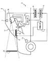
- an in-vehicle display device 1 is a device mounted on a main vehicle 2 of a user (driver), and includes an image output circuit (image control device / means) 3, a liquid crystal panel (display unit, or Display device / means) 5, camera 7, obstacle recognition circuit (obstacle recognition device / means) 9, risk setting circuit 11, vehicle speed sensor 13, and speaker 14.
- the image output circuit 3 outputs image data to the liquid crystal panel.
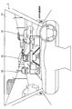
- the liquid crystal panel 5 is disposed on the upper part of the instrument panel 15 and displays an image output from the image output circuit 3.
- Light for displaying an image output from the liquid crystal panel 5 is reflected by the windshield 17 and enters the driver's viewpoint 19.
- a virtual image 21 of the image displayed on the liquid crystal panel 5 is displayed at a position away from the windshield 17 by a predetermined distance in front of the vehicle.
- the image output circuit 3 and the liquid crystal panel 5 are within the predetermined displayable range in the lower part of the windshield 17 of the main vehicle 2.
- a virtual image 21 (hereinafter referred to as “obstacle image”) indicating the presence of the obstacle at a position moved vertically downward of the driver's line of sight to the obstacle (in FIG. 2, the other vehicle 23) existing in front of the main vehicle 2. 33 ”) can be displayed.
- the image output circuit 3 and the liquid crystal panel 5 can change the color tone of the virtual image 21 to various colors.
- the displayable range of the virtual image 21 is set to be smaller than the field of view through the windshield 17 of the driver so as not to hinder driving, and a fixed portion of the lower portion of the windshield 17 (the combiner is windshielded).
- the virtual image 21 transmitted from (which may be attached to 17) is displayed.
- the camera 7 is an imaging device for taking a picture in front of the main vehicle 2 (hereinafter referred to as “front picture”).
- the camera 7 is a stereo camera that can acquire information on the depth direction by simultaneously photographing the front of the main vehicle 2 from a plurality of different directions, and is located near the driver's viewpoint 19 in the passenger compartment of the main vehicle 2.
- the obstacle recognition circuit 9 determines whether or not an obstacle (for example, another vehicle 23) exists in the front image captured by the camera 7, and if there is, the obstacle direction (viewed from the viewpoint 19). The direction to the obstacle), the obstacle distance (distance from the main vehicle 2 to the obstacle), and the size of the obstacle. These calculations are performed for each obstacle when a plurality of obstacles are recognized simultaneously, and can be performed using a known image recognition technique based on the shape, movement, and brightness of each obstacle. it can.
- the vehicle speed sensor 13 detects the speed of the vehicle and outputs the result to the risk setting circuit 11.
- the speaker 14 is installed in the passenger compartment of the main vehicle 2 and can output a warning sound according to the risk setting result in the risk setting circuit 11.
- the danger level setting circuit 11 is a circuit that sets the danger level of the obstacle recognized by the obstacle recognition circuit 9. Specifically, the risk setting circuit 11 calculates an arrival time required for the main vehicle 2 to reach the obstacle based on the vehicle speed of the main vehicle 2 obtained from the vehicle speed sensor 13 and the obstacle distance. If the arrival time becomes shorter than a threshold time designated in advance, it is determined that the warning sound is output at a necessary level, and the risk level is set.
- the image output circuit 3 and the obstacle recognition circuit 9 are configured by one or more computers.
- the CPU uses the RAM as a work area based on a program stored in the ROM.
- the following display control processing is executed.
- these various types of processing may be realized as a hardware configuration as one or a plurality of ICs. This display control process is started, for example, when the engine of the main vehicle 2 is turned on.
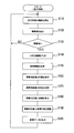
- step 110 the camera 7 starts capturing a front image of the main vehicle 2.
- the obstacle recognition circuit 9 extracts an obstacle from the front image acquired from the camera 7 in step 110.
- the shape, size, color, etc. of a specific obstacle for example, another vehicle, pedestrian, etc.
- step 130 the obstacle recognition circuit 9 determines whether or not the obstacle has been extracted from the front video in step 120. If it can be extracted, the process proceeds to step 140. If it cannot be extracted, the process returns to step 110.
- the obstacle recognition circuit 9 determines the direction of the extracted obstacle (direction to the obstacle viewed from the viewpoint 19), the obstacle distance (distance from the main vehicle 2 to the obstacle), and the size of the obstacle. Is calculated. This calculation is realized by, for example, using a known stereo correlation method, converting the forward image from the camera 7 into three-dimensional information, and generating three-dimensional coordinate information indicating the position of the obstacle. The obstacle recognition circuit 9 outputs this three-dimensional coordinate information to the image output circuit 3.
- the obstacle recognition circuit 9 calculates the viewing angle formed by the obstacle as viewed from the viewpoint 19 based on the obstacle size and obstacle distance calculated in step 140. This calculation is performed, for example, by obtaining a tangent between the converted distance and the height and width of the obstacle using a distance conversion table that converts the obstacle distance into the distance from the viewpoint 19 to the obstacle. Realized. Based on this value, the obstacle recognition circuit 9 determines the size (height and width) of the obstacle projected on the driver's eyes, that is, the size of the obstacle (high) that the driver can see through the windshield 17. Viewing angle information indicating (width and width) is generated and output to the image output circuit 3.
- the distance conversion table is stored in a storage device such as a ROM readable by the CPU.
- the image output circuit 3 determines the obstacle image 33 according to the type (for example, other vehicle or pedestrian) and the color of the obstacle extracted by the obstacle recognition circuit 9 in step 120.
- the color tone For example, when the obstacle type is a pedestrian, the color tone of the obstacle image 33 is set to a darker color than other vehicles, or when the obstacle type is another vehicle, The color tone of the obstacle image 33 is set to a color similar to the color.
- the image output circuit 3 sets the shape of the obstacle image 33 whose color tone has been set in step 160 based on the viewing angle information input from the obstacle recognition circuit 9 in step 150.
- the shape correspondence table in which the viewing angle information (the height and width of the obstacle that the driver can see through the windshield 17) and the shape (height and width) of the obstacle image 33 are associated with each other. And realized by obtaining the shape of the obstacle image 33 corresponding to the viewing angle information.
- the shape correspondence table is stored in a storage device such as a ROM readable by the CPU.
- step 180 the image output circuit 3 is based on the three-dimensional information input from the obstacle recognition circuit 9 in step 140. And the intersection of the virtual image 21 displayable range (hereinafter referred to as a “virtual image display surface”) at a location separated from the windshield 17 by a predetermined distance (for example, about 2 m).
- a predetermined distance for example, about 2 m.
- the displayable area is located below, and the line of sight to the obstacle is often above the virtual image marking surface. In this case, for example, the intersection of a line obtained by moving the line of sight vertically downward and the uppermost end of the virtual image display surface is calculated.
- a virtual plane extending vertically downward is drawn from the line of sight to the obstacle, and the first intersection of the virtual plane and the virtual image display surface is calculated.
- the coordinates of the intersection hereinafter referred to as the line of sight corresponding to the line
- the line of sight corresponding where the driver's line of sight to the obstacle is moved vertically downward
- the uppermost end of the virtual image display surface hereinafter referred to as coordinates on the line of sight corresponding to ").
- step 190 the image output circuit 3 variably sets the height direction of the coordinates on the line of sight corresponding to the line of sight calculated in step 180 according to the obstacle distance calculated by the obstacle recognition circuit 9 in step 140. For example, when the obstacle distance is large, the height of the coordinate on the line of sight is increased, and when the obstacle distance is small, the height of the coordinate on the line of sight corresponding is decreased.
- step 200 the image output circuit 3 generates image data for displaying the obstacle image set in step 160 and step 170 at the coordinates on the line of sight corresponding to the line set in step 190. Output to the liquid crystal panel 5.
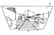
- the virtual image 21 (obstacle image 33) displayed based on the image data is a line of sight corresponding to the line of sight to the obstacle (in FIG. 2, another vehicle 23) as seen from the driver. It is displayed at a position on the corresponding line.
- the obstacle image 33 is a viewing angle formed by the obstacle (in FIG. 2, the other vehicle 23) as viewed from the driver, that is, the size (height and width) of the obstacle that the driver can see through the windshield 17. ) Is displayed in a size corresponding to.
- the obstacle image 33 is displayed at a higher position as an image with respect to a distant obstacle is viewed from the main vehicle 2 (and thus a driver), and is displayed at a lower position as an image with respect to a nearby obstacle.
- the white line image 34 indicating the road on which the vehicle is traveling can be displayed as the virtual image 21 together with the obstacle image 33.
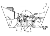
- the obstacle recognition circuit 9 generates three-dimensional information indicating the position of the obstacle.
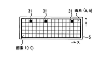
- this three-dimensional information is an obstacle based on a combination of coordinates in the X direction (vehicle width direction), coordinates in the Y direction (vehicle height direction), and coordinates in the Z direction (depth direction). Expressed as 25 directions.
- a storage unit such as a ROM (not shown) of the in-vehicle display device 1 has coordinates between the three-dimensional information of the obstacle 25 generated by the obstacle recognition circuit 9 and the display coordinates on the liquid crystal panel 5. A correspondence table is stored. As shown in FIG.
- the image output circuit 3 calculates the coordinates on the line of sight corresponding to the obstacle 25 in the liquid crystal panel 5 using the three-dimensional information generated by the obstacle recognition circuit 9 and the coordinate correspondence table described above.
- the obstacle image 33 in which the color tone and size are set in advance is viewed from the driver to the obstacle 25. Is displayed at a position on the line of sight corresponding to the line of sight.
- the obstacle recognition circuit 9 recognizes the obstacle 25 existing around the main vehicle 2, and the image output circuit 3 is recognized by the obstacle recognition circuit 9.
- An obstacle image 33 indicating the object 25 is displayed at a position corresponding to the driver's line of sight corresponding to the obstacle 25 within a predetermined displayable range in the lower part of the windshield 17.
- the display position of the obstacle image is determined based on how the obstacle is seen from the driver or the relative position of the obstacle in the forward field of view, and the obstacle image is displayed.
- the obstacle image 33 when the obstacle image 33 is displayed within a predetermined displayable range, the actual obstacle 25 is positioned on an extension line in which the driver looks at the obstacle image 33. Therefore, the obstacle image 33 serves as a so-called signpost that allows the driver to understand the actual position of the obstacle 25 by moving the eyes relatively easily, so that the driver can deal with the obstacle image 33 and the obstacle 25. It can be made easy to grasp.
- the obstacle image 33 is displayed as a virtual image in the lower portion of the windshield 17, the obstacle image 33 does not have to be superimposed on the actual obstacle, and the obstacle image 33 is actually It is possible to avoid the trouble and danger that the obstacles are difficult to see.
- the corresponding obstacle image 33 is displayed immediately. Since it is possible for the driver to take action between the obstacle image 33 and the obstacle 25, a delay in information transmission to the driver can also be avoided.
- the in-vehicle display device 1 it is possible to make the driver easily grasp the correspondence between the obstacle image 33 and the obstacle 25 displayed in the predetermined displayable range, and as a result, construct a user-friendly system. Can do.
- Examples of the system including the in-vehicle display device 1 include a well-known auto cruise control system and a key plane control system.
- the obstacle 25 is detected (recognized) in these systems. Can be suitably transmitted to the driver.
- the obstacle recognition circuit 9 recognizes a plurality of obstacles 25 existing in front of the main vehicle 2 at the same time, and the image output circuit 3 uses the obstacle recognition circuit 9 to recognize a plurality of obstacles 25. Is recognized. In this case, by using a plurality of obstacle images 33 showing the plurality of obstacles 25, how the plurality of obstacles 25 are seen from the driver's seat through the windshield 17 of the main vehicle 2, in other words, relative positions.
- the display of the liquid crystal panel 5 is controlled so as to reproduce the relationship within the displayable range.
- the displayable range is determined in front of the driver's seat of the main vehicle 2, the psychological stress of not knowing where the image is displayed can be eliminated, and the line of sight can be displayed in a predetermined manner. Since the driver can intuitively recognize the presence / absence and number of obstacle images 33 by turning to the range, the burden on the driver can be reduced.
- the correspondence between the obstacle image 33 and the obstacle 25 displayed in the predetermined displayable range can be easily grasped by the driver, and a user-friendly system can be constructed.
- a head-up display that reflects light for displaying an image by the windshield 17 (or a combiner), outputs the reflected light to the driver's eyes, and displays the image as a virtual image in front of the main vehicle 2. Since the obstacle image 33 is displayed using the button, the obstacle image 33 can be recognized by the driver without looking away from the windshield 17 during driving, so that the usability can be further improved.
- the image output circuit 3 displays the obstacle image 33 in a size corresponding to the viewing angle formed by the obstacle 25 when viewed from the driver. Since the size of the obstacle image 33 is changed according to the size of the obstacle 25, the driver can intuitively recognize a sense of distance from the obstacle 25 or the like depending on the size of the obstacle image 33. it can. For example, when a plurality of obstacles 25 are scattered and the obstacle images 33 are displayed for all the obstacles 25, the difference in the size of the obstacle images 33 may cause the driver to It is possible to intuitively recognize a sense of relative distance from a plurality of obstacles 25.
- the image output circuit 3 displays the obstacle image 33 in a size corresponding to the height and width of the obstacle 25, so that according to the size of the actual obstacle 25, Since the size of the obstacle image 33 is changed, the driver can intuitively recognize the size of the obstacle 25 based on the size of the obstacle image 33.
- the image output circuit 3 displays the obstacle image 33 in a size corresponding to the viewing angle formed by the obstacle 25 in the height direction and the width direction when viewed from the driver.
- the driver can intuitively understand information having elements of both a sense of distance from the obstacle 25 and a size.
- the image output circuit 3 displays the obstacle image 33 having a color tone corresponding to the obstacle 25. Therefore, the obstacle image 33 and the actual obstacle 25 are changed depending on the color tone of the obstacle image 33. Can be made easier to understand.
- the image output circuit 3 variably sets the display position of the obstacle image 33 according to the distance between the main vehicle 2 and the obstacle 25. Specifically, by changing the height of the obstacle image 33 within the displayable range according to the distance from the obstacle 25, the display position of the image with respect to a distant obstacle is increased, and the image of the image with respect to a nearby obstacle is increased. Since the position is lowered, the sense of distance from the obstacle 25 can be displayed more easily.
- this indication is not limited to the above-mentioned embodiment, and can be carried out in various modes in the range which does not deviate from the gist of this indication.
- the obstacle recognition circuit 9 generates various information related to the obstacle based on the front image captured by the camera 7, but the present invention is not limited to this.
- various types of information related to obstacles may be generated based on information obtained from a known radar device instead of the camera 7.
- the height of the obstacle image 33 within the displayable range is changed according to the distance from the obstacle 25, thereby increasing the display position of the image with respect to the distant obstacle.
- the display position is variably set so that the image with respect to the nearby obstacle moves, and attention is paid to the driver. You may let them.
- the mechanism of the head-up display is used to display the obstacle image 33 in the lower part of the windshield 17.
- the present invention is not limited to this. If an image is displayed in the lower part of the windshield (specifically, an image is displayed within a predetermined displayable range arranged in front of the driver's seat of the main vehicle 2), for example, the windshield A general liquid crystal display or a film-like display (display device) provided in front (front of the driver's seat) may be used. Further, as long as the windshield of the main vehicle 2 is used, an image may be displayed not only in the windshield 17 but also in a lower part of the rear or side windshield of the main vehicle 2.
Landscapes
- Engineering & Computer Science (AREA)
- Physics & Mathematics (AREA)
- General Physics & Mathematics (AREA)
- Mechanical Engineering (AREA)
- Theoretical Computer Science (AREA)
- Transportation (AREA)
- Computer Vision & Pattern Recognition (AREA)
- Chemical & Material Sciences (AREA)
- Combustion & Propulsion (AREA)
- Optics & Photonics (AREA)
- Multimedia (AREA)
- Instrument Panels (AREA)
- Traffic Control Systems (AREA)
Priority Applications (2)
| Application Number | Priority Date | Filing Date | Title |
|---|---|---|---|
| US14/897,583 US9878667B2 (en) | 2013-06-14 | 2014-05-26 | In-vehicle display apparatus and program product |
| DE112014002804.5T DE112014002804T5 (de) | 2013-06-14 | 2014-05-26 | Innenanzeigevorrichtung für Fahrzeuge und Programmprodukt |
Applications Claiming Priority (2)
| Application Number | Priority Date | Filing Date | Title |
|---|---|---|---|
| JP2013125597A JP5999032B2 (ja) | 2013-06-14 | 2013-06-14 | 車載表示装置およびプログラム |
| JP2013-125597 | 2013-06-14 |
Publications (1)
| Publication Number | Publication Date |
|---|---|
| WO2014199574A1 true WO2014199574A1 (ja) | 2014-12-18 |
Family
ID=52021895
Family Applications (1)
| Application Number | Title | Priority Date | Filing Date |
|---|---|---|---|
| PCT/JP2014/002741 WO2014199574A1 (ja) | 2013-06-14 | 2014-05-26 | 車載表示装置およびプログラム製品 |
Country Status (4)
| Country | Link |
|---|---|
| US (1) | US9878667B2 (de) |
| JP (1) | JP5999032B2 (de) |
| DE (1) | DE112014002804T5 (de) |
| WO (1) | WO2014199574A1 (de) |
Cited By (1)
| Publication number | Priority date | Publication date | Assignee | Title |
|---|---|---|---|---|
| JP2018106655A (ja) * | 2016-12-28 | 2018-07-05 | 株式会社リコー | Hud装置、車両装置及び表示方法 |
Families Citing this family (21)
| Publication number | Priority date | Publication date | Assignee | Title |
|---|---|---|---|---|
| TWM492262U (zh) * | 2014-07-18 | 2014-12-21 | Seeways Technology Inc | 自動顯示三態視角之倒車顯影系統及其倒車攝影裝置 |
| KR102263725B1 (ko) * | 2014-11-21 | 2021-06-11 | 현대모비스 주식회사 | 주행 정보 제공 장치 및 주행 정보 제공 방법 |
| JP6415943B2 (ja) | 2014-11-21 | 2018-10-31 | 三菱重工サーマルシステムズ株式会社 | ヒートポンプ式車両用空調システム |
| JP6520668B2 (ja) * | 2015-02-09 | 2019-05-29 | 株式会社デンソー | 車両用表示制御装置及び車両用表示ユニット |
| JP6486474B2 (ja) * | 2015-08-03 | 2019-03-20 | 三菱電機株式会社 | 表示制御装置、表示装置及び表示制御方法 |
| JP2017123029A (ja) * | 2016-01-06 | 2017-07-13 | 富士通株式会社 | 情報通知装置、情報通知方法及び情報通知プログラム |
| JP6512449B2 (ja) | 2016-01-20 | 2019-05-15 | パナソニックIpマネジメント株式会社 | 表示装置 |
| DE102016001204B4 (de) * | 2016-02-03 | 2021-07-08 | Audi Ag | Kraftfahrzeug |
| DE102016001201B4 (de) * | 2016-02-03 | 2021-07-08 | Audi Ag | Kraftfahrzeug |
| JP6658859B2 (ja) | 2016-02-18 | 2020-03-04 | 株式会社リコー | 情報提供装置 |
| DE102016211737A1 (de) * | 2016-06-29 | 2018-01-04 | Bayerische Motoren Werke Aktiengesellschaft | Kraftfahrzeug |
| US10671071B2 (en) * | 2016-08-09 | 2020-06-02 | Nissan Motor Co., Ltd. | Control method and control device of automatic driving vehicle |
| DE102016225346A1 (de) | 2016-12-16 | 2018-06-21 | Robert Bosch Gmbh | Verfahren zum Ermitteln eines Anzeigebereichs mindestens eines Elements auf einer Anzeigevorrichtung |
| US20200152157A1 (en) * | 2017-06-28 | 2020-05-14 | Nippon Seiki Co., Ltd. | Image processing unit, and head-up display device provided with same |
| US10495733B2 (en) * | 2018-02-26 | 2019-12-03 | GM Global Technology Operations LLC | Extendable sensor mount |
| WO2020194686A1 (ja) * | 2019-03-28 | 2020-10-01 | 本田技研工業株式会社 | 鞍乗り型車両の運転支援システム |
| WO2020230612A1 (ja) * | 2019-05-15 | 2020-11-19 | 日産自動車株式会社 | 表示制御方法及び表示制御装置 |
| JP7206010B2 (ja) * | 2019-09-19 | 2023-01-17 | 株式会社 ミックウェア | 制御装置 |
| JP7347406B2 (ja) * | 2020-11-30 | 2023-09-20 | トヨタ自動車株式会社 | 画像表示装置、プログラム及び画像表示方法 |
| JP2022139953A (ja) * | 2021-03-12 | 2022-09-26 | 本田技研工業株式会社 | 注意喚起システム、及び注意喚起方法 |
| JP2022139951A (ja) * | 2021-03-12 | 2022-09-26 | 本田技研工業株式会社 | 注意喚起システム、及び注意喚起方法 |
Citations (6)
| Publication number | Priority date | Publication date | Assignee | Title |
|---|---|---|---|---|
| JPH10307545A (ja) * | 1997-05-07 | 1998-11-17 | Shimadzu Corp | ヘッドアップディスプレイ |
| JP2001023091A (ja) * | 1999-07-07 | 2001-01-26 | Honda Motor Co Ltd | 車両の画像表示装置 |
| JP2002019491A (ja) * | 2000-07-11 | 2002-01-23 | Mazda Motor Corp | 車両の表示装置 |
| JP2009196630A (ja) * | 2008-01-25 | 2009-09-03 | Denso Corp | 表示装置 |
| JP2009205268A (ja) * | 2008-02-26 | 2009-09-10 | Honda Motor Co Ltd | 障害物表示装置 |
| JP2011240813A (ja) * | 2010-05-18 | 2011-12-01 | Toshiba Alpine Automotive Technology Corp | 車両用ディスプレイ装置及び車両用ディスプレイ方法 |
Family Cites Families (7)
| Publication number | Priority date | Publication date | Assignee | Title |
|---|---|---|---|---|
| JP2006276964A (ja) | 2005-03-28 | 2006-10-12 | Nippon Seiki Co Ltd | 車両用表示装置 |
| JP2009190520A (ja) | 2008-02-13 | 2009-08-27 | Toyota Motor Corp | 車両用表示装置 |
| US20090225434A1 (en) * | 2008-03-10 | 2009-09-10 | Nicholas Clayton L | Vehicle rear view apparatus utilizing heads up display and rear looking sensors |
| JP2009217682A (ja) | 2008-03-12 | 2009-09-24 | Yazaki Corp | 車両用表示装置 |
| US20110301813A1 (en) * | 2010-06-07 | 2011-12-08 | Denso International America, Inc. | Customizable virtual lane mark display |
| JP2012063524A (ja) | 2010-09-15 | 2012-03-29 | Nippon Seiki Co Ltd | 車両用ヘッドアップディスプレイ装置 |
| US8810381B2 (en) * | 2012-06-29 | 2014-08-19 | Yazaki North America, Inc. | Vehicular heads up display with integrated bi-modal high brightness collision warning system |
-
2013
- 2013-06-14 JP JP2013125597A patent/JP5999032B2/ja active Active
-
2014
- 2014-05-26 DE DE112014002804.5T patent/DE112014002804T5/de active Pending
- 2014-05-26 WO PCT/JP2014/002741 patent/WO2014199574A1/ja active Application Filing
- 2014-05-26 US US14/897,583 patent/US9878667B2/en active Active
Patent Citations (6)
| Publication number | Priority date | Publication date | Assignee | Title |
|---|---|---|---|---|
| JPH10307545A (ja) * | 1997-05-07 | 1998-11-17 | Shimadzu Corp | ヘッドアップディスプレイ |
| JP2001023091A (ja) * | 1999-07-07 | 2001-01-26 | Honda Motor Co Ltd | 車両の画像表示装置 |
| JP2002019491A (ja) * | 2000-07-11 | 2002-01-23 | Mazda Motor Corp | 車両の表示装置 |
| JP2009196630A (ja) * | 2008-01-25 | 2009-09-03 | Denso Corp | 表示装置 |
| JP2009205268A (ja) * | 2008-02-26 | 2009-09-10 | Honda Motor Co Ltd | 障害物表示装置 |
| JP2011240813A (ja) * | 2010-05-18 | 2011-12-01 | Toshiba Alpine Automotive Technology Corp | 車両用ディスプレイ装置及び車両用ディスプレイ方法 |
Cited By (2)
| Publication number | Priority date | Publication date | Assignee | Title |
|---|---|---|---|---|
| JP2018106655A (ja) * | 2016-12-28 | 2018-07-05 | 株式会社リコー | Hud装置、車両装置及び表示方法 |
| US10845592B2 (en) | 2016-12-28 | 2020-11-24 | Ricoh Company, Ltd. | Head-up display, vehicle apparatus, display method, and recording medium |
Also Published As
| Publication number | Publication date |
|---|---|
| US20160121794A1 (en) | 2016-05-05 |
| JP5999032B2 (ja) | 2016-09-28 |
| DE112014002804T5 (de) | 2016-03-31 |
| US9878667B2 (en) | 2018-01-30 |
| JP2015000630A (ja) | 2015-01-05 |
Similar Documents
| Publication | Publication Date | Title |
|---|---|---|
| JP5999032B2 (ja) | 車載表示装置およびプログラム | |
| JP5962594B2 (ja) | 車載表示装置およびプログラム | |
| US9620009B2 (en) | Vehicle surroundings monitoring device | |
| JP4475308B2 (ja) | 表示装置 | |
| JP6459205B2 (ja) | 車両用表示システム | |
| US9463743B2 (en) | Vehicle information display device and vehicle information display method | |
| CN110786004B (zh) | 显示控制装置、显示控制方法及存储介质 | |
| EP4339938A1 (de) | Projektionsverfahren und -vorrichtung sowie fahrzeug und ar-hud | |
| US9836814B2 (en) | Display control apparatus and method for stepwise deforming of presentation image radially by increasing display ratio | |
| JP2013168063A (ja) | 画像処理装置、画像表示システム及び画像処理方法 | |
| US20240042857A1 (en) | Vehicle display system, vehicle display method, and computer-readable non-transitory storage medium storing vehicle display program | |
| JP6186905B2 (ja) | 車載表示装置およびプログラム | |
| WO2016013167A1 (ja) | 車両用表示制御装置 | |
| JP2019188855A (ja) | 車両用視認装置 | |
| JP6394940B2 (ja) | 車両用表示システム | |
| KR101209796B1 (ko) | 전경 투과 기능을 갖는 차량용 표시장치 및 이의 표시방법 | |
| US20240017669A1 (en) | Image processing apparatus, image processing method, and image processing system | |
| JP2016070951A (ja) | 表示装置、制御方法、プログラム、及び記憶媒体 | |
| KR20170056100A (ko) | 헤드업 디스플레이의 물체 표시 장치 및 방법 | |
| JP5310616B2 (ja) | 車両周辺表示装置 | |
| US20200231099A1 (en) | Image processing apparatus | |
| JP6476644B2 (ja) | 認知補助装置 | |
| US20150130938A1 (en) | Vehicle Operational Display | |
| JP2015092346A (ja) | 表示装置 | |
| JP2019064422A (ja) | ヘッドアップディスプレイ装置 |
Legal Events
| Date | Code | Title | Description |
|---|---|---|---|
| 121 | Ep: the epo has been informed by wipo that ep was designated in this application |
Ref document number: 14811717 Country of ref document: EP Kind code of ref document: A1 |
|
| WWE | Wipo information: entry into national phase |
Ref document number: 14897583 Country of ref document: US |
|
| WWE | Wipo information: entry into national phase |
Ref document number: 112014002804 Country of ref document: DE |
|
| 122 | Ep: pct application non-entry in european phase |
Ref document number: 14811717 Country of ref document: EP Kind code of ref document: A1 |