WO2014199571A1 - 炭化珪素単結晶の製造方法 - Google Patents
炭化珪素単結晶の製造方法 Download PDFInfo
- Publication number
- WO2014199571A1 WO2014199571A1 PCT/JP2014/002695 JP2014002695W WO2014199571A1 WO 2014199571 A1 WO2014199571 A1 WO 2014199571A1 JP 2014002695 W JP2014002695 W JP 2014002695W WO 2014199571 A1 WO2014199571 A1 WO 2014199571A1
- Authority
- WO
- WIPO (PCT)
- Prior art keywords
- single crystal
- growth
- shaft
- crystal
- silicon carbide
- Prior art date
- Legal status (The legal status is an assumption and is not a legal conclusion. Google has not performed a legal analysis and makes no representation as to the accuracy of the status listed.)
- Ceased
Links
Images





Classifications
-
- C—CHEMISTRY; METALLURGY
- C30—CRYSTAL GROWTH
- C30B—SINGLE-CRYSTAL GROWTH; UNIDIRECTIONAL SOLIDIFICATION OF EUTECTIC MATERIAL OR UNIDIRECTIONAL DEMIXING OF EUTECTOID MATERIAL; REFINING BY ZONE-MELTING OF MATERIAL; PRODUCTION OF A HOMOGENEOUS POLYCRYSTALLINE MATERIAL WITH DEFINED STRUCTURE; SINGLE CRYSTALS OR HOMOGENEOUS POLYCRYSTALLINE MATERIAL WITH DEFINED STRUCTURE; AFTER-TREATMENT OF SINGLE CRYSTALS OR A HOMOGENEOUS POLYCRYSTALLINE MATERIAL WITH DEFINED STRUCTURE; APPARATUS THEREFOR
- C30B25/00—Single-crystal growth by chemical reaction of reactive gases, e.g. chemical vapour-deposition growth
- C30B25/02—Epitaxial-layer growth
- C30B25/12—Substrate holders or susceptors
-
- C—CHEMISTRY; METALLURGY
- C30—CRYSTAL GROWTH
- C30B—SINGLE-CRYSTAL GROWTH; UNIDIRECTIONAL SOLIDIFICATION OF EUTECTIC MATERIAL OR UNIDIRECTIONAL DEMIXING OF EUTECTOID MATERIAL; REFINING BY ZONE-MELTING OF MATERIAL; PRODUCTION OF A HOMOGENEOUS POLYCRYSTALLINE MATERIAL WITH DEFINED STRUCTURE; SINGLE CRYSTALS OR HOMOGENEOUS POLYCRYSTALLINE MATERIAL WITH DEFINED STRUCTURE; AFTER-TREATMENT OF SINGLE CRYSTALS OR A HOMOGENEOUS POLYCRYSTALLINE MATERIAL WITH DEFINED STRUCTURE; APPARATUS THEREFOR
- C30B25/00—Single-crystal growth by chemical reaction of reactive gases, e.g. chemical vapour-deposition growth
- C30B25/02—Epitaxial-layer growth
- C30B25/16—Controlling or regulating
-
- C—CHEMISTRY; METALLURGY
- C30—CRYSTAL GROWTH
- C30B—SINGLE-CRYSTAL GROWTH; UNIDIRECTIONAL SOLIDIFICATION OF EUTECTIC MATERIAL OR UNIDIRECTIONAL DEMIXING OF EUTECTOID MATERIAL; REFINING BY ZONE-MELTING OF MATERIAL; PRODUCTION OF A HOMOGENEOUS POLYCRYSTALLINE MATERIAL WITH DEFINED STRUCTURE; SINGLE CRYSTALS OR HOMOGENEOUS POLYCRYSTALLINE MATERIAL WITH DEFINED STRUCTURE; AFTER-TREATMENT OF SINGLE CRYSTALS OR A HOMOGENEOUS POLYCRYSTALLINE MATERIAL WITH DEFINED STRUCTURE; APPARATUS THEREFOR
- C30B29/00—Single crystals or homogeneous polycrystalline material with defined structure characterised by the material or by their shape
- C30B29/10—Inorganic compounds or compositions
- C30B29/36—Carbides
Definitions
- the present disclosure relates to a method for manufacturing a silicon carbide (hereinafter referred to as SiC) single crystal that can be used as a material such as a power MOSFET.
- SiC silicon carbide
- Patent Document 1 a method shown in Patent Document 1 has been proposed as a method for producing an SiC single crystal by growing an SiC single crystal on a seed crystal.
- the SiC single crystal is grown on the surface of the seed crystal by a gas growth method in which an SiC source gas is supplied to the surface of the seed crystal composed of the SiC single crystal.
- the gas supply amount to the growth surface should be uniform, and the SiC polycrystal generated around the SiC single crystal The SiC single crystal is rotated to prevent sticking.
- the temperature distribution on the growth surface is adjusted so that the growth surface becomes flat growth or convex growth with a convex shape.
- a SiC single crystal is grown while being controlled.
- This disclosure is intended to provide a method for producing a SiC single crystal that allows a high-quality SiC single crystal to be grown at a higher speed.
- the method for producing a silicon carbide single crystal includes disposing a pedestal in a heating vessel constituting a reaction chamber for growing a silicon carbide single crystal, attaching a seed crystal to the pedestal, and heating the heating
- the source gas is thermally decomposed in the heating vessel and supplied to the surface of the seed crystal, and the silicon carbide single crystal is grown on the surface of the seed crystal, It is determined whether the growth rate of the silicon carbide single crystal is within a threshold range centered on a target value, whether it is larger than the upper limit value of the threshold range, or smaller than the lower limit value of the threshold range, and within the threshold range If so, the rotation speed of the seed crystal is maintained, and if the rotation speed is larger than the upper limit value of the threshold range, the rotation speed is maintained or decreased, and if the rotation speed is smaller than the lower limit value of the threshold range, the rotation speed With increasing speed
- the growth surface of the SiC single crystal is rotated by rotating the pedestal and the seed crystal at a predetermined rotation speed, and the growth rate of the SiC single crystal is increased or decreased.
- the rotation speed is controlled based on whether or not it is. Specifically, if the growth rate is larger than the upper limit value of the threshold range centered on the target value, the rotation speed is maintained or decreased, and if the growth rate is smaller than the lower limit value of the threshold range, the rotation speed is increased. If the growth is convex, the rotation speed is maintained or decreased, and if the growth is concave, the rotation speed is increased.
- the SiC single crystal can be grown flat or convex by controlling the rotation speed according to the growth speed while allowing the SiC single crystal growth surface to rotate at a high speed of, for example, 500 rpm or higher. Can be controlled. This makes it possible to grow a high-quality SiC single crystal at a higher speed.
- FIG. 1 is a cross-sectional view of a crystal manufacturing apparatus according to a first embodiment of the present disclosure
- FIG. 2 is a diagram showing the growth rate at each part of the growth surface when the growth surface of the SiC single crystal is not rotated and when the rotation speed is changed and rotated.
- FIG. 3 is a diagram showing a change in the growth rate with respect to the rotation speed for each of the crystal center that is the center of the growth surface of the SiC single crystal and the crystal edge that is the outer peripheral position.
- FIG. 4 is a diagram showing the relationship between the growth rate and the flatness
- FIG. 5 is a cross-sectional view of a crystal manufacturing apparatus according to a third embodiment of the present disclosure
- FIG. 6 is a diagram illustrating the etching rate of the seed crystal when the shaft is rotated at a high speed without introducing the SiC source gas described in the fourth embodiment of the present disclosure
- FIG. 7 is a diagram showing the relationship between the supply amount of the SiC source gas and the rotational speed of the shaft with respect to the temperature change in the heating container
- FIG. 8 is a diagram showing the relationship between the supply amount of the SiC source gas and the rotational speed of the shaft with respect to the temperature change in the heating container described in the modification of the fourth embodiment.
- FIG. 9 is a partial enlarged cross-sectional view of the crystal manufacturing apparatus according to the fifth embodiment of the present disclosure; FIG.
- FIG. 10 is a sectional view taken along line XX in FIG. 11 is a sectional view taken along line XI-XI in FIG.
- FIG. 12 is a cross-sectional view of the crystal manufacturing apparatus according to the sixth embodiment of the present disclosure
- FIG. 13 is an enlarged cross-sectional view of the vicinity of the pedestal in the crystal manufacturing apparatus shown in FIG.
- FIG. 14 is a perspective view of a cross section of the shaft taken along line XIV-XIV in FIG.
- an inlet 2 is provided at the bottom of the crystal manufacturing apparatus 1, and an SiC source gas 3a from a source gas supply source 3 is introduced through the inlet 2 together with a carrier gas and an etching gas.
- the crystal production apparatus 1 is provided with an outlet 4 at the top, and the unreacted gas in the SiC raw material gas 3 a is discharged through the outlet 4.
- the crystal manufacturing apparatus 1 forms the ingot of the SiC single crystal 20 by growing a SiC single crystal on the seed crystal 5 which consists of a SiC single crystal substrate arrange
- the crystal manufacturing apparatus 1 includes a source gas supply source 3, a vacuum container 6, a lower heat insulating material 7, a heating container 8, a pedestal 9, a peripheral heat insulating material 10, a rotary pulling mechanism 11, first and second. Heating devices 12 and 13, a temperature measuring unit 14, a growth and shape observation unit 15, and a control device 16 are provided.
- the raw material gas supply source 3 supplies a SiC raw material gas 3a containing Si and C together with a carrier gas and an etching gas from the inlet 2.
- a SiC raw material gas 3a a mixed gas of a silane gas such as silane and silicon tetrachloride and a hydrocarbon gas such as propane is used.
- the vacuum vessel 6 is made of quartz glass or the like and is made of a hollow cylindrical member.
- the vacuum vessel 6 can introduce and lead the carrier gas, the etching gas, and the SiC raw material gas 3a, and accommodates other components of the crystal manufacturing apparatus 1 and evacuates the pressure of the accommodated internal space. Therefore, the pressure can be reduced.
- An inlet 2 for SiC source gas 3a or the like is provided at the bottom of the vacuum vessel 6, and an outlet 4 for SiC source gas 3a or the like is provided at the top (specifically, above the side wall).
- the lower heat insulating material 7 has a cylindrical shape, is coaxially arranged with respect to the vacuum vessel 6, and constitutes a gas introduction pipe 7a into which the SiC raw material gas 3a and the like are introduced by the hollow portion.
- the lower heat insulating material 7 is made of, for example, graphite or graphite whose surface is coated with refractory metal carbide such as TaC (tantalum carbide), NbC (niobium carbide), ZrC (zirconium carbide), etc., so that thermal etching can be performed. It can be suppressed.
- the lower heat insulating material 7 may have a temperature measurement hole.
- the heating vessel 8 constitutes a reaction chamber for growing the SiC single crystal 20 on the surface of the seed crystal 5.
- a refractory metal carbide such as TaC, NbC, ZrC or TaC
- thermal etching can be suppressed.
- the heating container 8 is arranged from the upstream side to the downstream side in the flow direction of the SiC raw material gas 3 a with respect to the base 9 so as to surround the base 9.
- the SiC source gas 3a is thermally decomposed while eliminating particles contained in the SiC source gas 3a until the SiC source gas 3a supplied from the inlet 2 is led to the seed crystal 5. .
- the heating container 8 has a structure having a hollow cylindrical member, and in the case of the present embodiment, is constituted by a bottomed cylindrical member.
- the heating vessel 8 is provided with a gas introduction port 8a that communicates with the hollow portion of the lower heat insulating material 7 at the bottom, and the SiC source gas 3a that has passed through the hollow portion of the lower heat insulating material 7 passes through the gas introduction port 8a. 8 is introduced.
- the pedestal 9 is a disk-shaped member disposed coaxially with the central axis of the heating container 8.
- a refractory metal carbide such as TaC, NbC, or ZrC, or TaC, NbC
- thermal etching can be suppressed.
- a seed crystal 5 is attached to the pedestal 9, and a SiC single crystal 20 is grown on the surface of the seed crystal 5.
- the outer periphery heat insulating material 10 insulates the heating container 8 and the outer peripheral side from it by surrounding the outer periphery of the heating container 8 and the base 9.
- the outer periphery heat insulating material 10 is comprised by the cylindrical shape, for example, and is arrange
- the outer peripheral insulating material 10 is also made of, for example, graphite or graphite whose surface is coated with a refractory metal carbide such as TaC, NbC, or ZrC, so that thermal etching can be suppressed.
- the rotary pulling mechanism 11 has a mechanism including a gear, a motor, and the like, and pulls up the shaft 11a while rotating the shaft 11a with a constant torque, for example.
- One end of the shaft 11 a is connected to the surface of the pedestal 9 on the side opposite to the attaching surface of the seed crystal 5, and the other end is connected to the main body of the rotary pulling mechanism 11.
- the shaft 11a is also made of, for example, graphite or graphite whose surface is coated with a refractory metal carbide such as TaC, so that thermal etching can be suppressed.
- the pedestal 9, the seed crystal 5 and the SiC single crystal 20 can be rotated and pulled together with the shaft 11a, and the growth surface of the SiC single crystal 20 has a desired temperature distribution. Along with the growth, it can be adjusted to a raising amount according to the growth amount. Moreover, the growth surface of the SiC single crystal 20 can be rotated.
- the first and second heating devices 12 and 13 are composed of induction heating coils and heaters, and are arranged so as to surround the vacuum vessel 6. These 1st, 2nd heating apparatuses 12 and 13 are comprised so that temperature control can be carried out independently, respectively. For this reason, finer temperature control can be performed.
- the first heating device 12 is disposed at a position corresponding to the lower side of the heating container 8.
- the second heating device 13 is disposed at a position corresponding to the base 9. Because of this arrangement, the temperature distribution on the growth surface of the SiC single crystal 20 can be adjusted to a temperature suitable for the growth of the SiC single crystal 20 by controlling the first and second heating devices 12 and 13. .
- the growth amount and shape observation unit 15 observes the growth amount of the SiC single crystal 20 and the shape of the growth surface.
- the growth amount and shape observation unit 15 is configured by, for example, an X-ray irradiator and the like, and by performing X irradiation on the growth surface of the SiC single crystal 20 from the outside of the heating vessel 8 and the outer peripheral heat insulating material 10, The shape is observed, and information corresponding to the observation result is fed back to the control device 16.
- the temperature measuring unit 14 measures the temperature of the growth surface of the SiC single crystal 20 and the temperature distribution in the growth surface.
- the temperature measurement unit 14 includes a radiation thermometer, a CCD camera, and the like.
- the temperature measurement unit 14 measures temperatures at various points on the growth surface of the SiC single crystal 20 through the inlet 2 and the gas introduction pipe 7a. Information corresponding to the measurement result is fed back to the control device 16.
- the measurement window is formed in the heating container 8 or the outer periphery heat insulating material 10, and the SiC single crystal 20 is passed through the measurement window. It is also possible to measure the temperature at various points on the growth surface of the film.
- the control device 16 controls the rotational speed and the pulling amount of the shaft 11a by the rotating pulling mechanism 11 based on the growth amount and the information sent from the shape observing unit 15 and the temperature measuring unit 14. Specifically, the control device 16 measures the growth rate (or growth amount) at various places of the SiC single crystal 20 based on the growth amount and the observation result in the shape observation unit 15, and rotates the shaft 11a based on the measurement rate. Control speed and lift. In addition, the control device 16 controls the first and second heating devices 12 and 13 so that the temperature and temperature distribution on the growth surface of the SiC single crystal 20 become values suitable for crystal growth based on the measurement result of the temperature measurement unit 14. The crystal shape is predicted based on the temperature and temperature distribution, and the rotation speed and the pulling amount are controlled. In addition, the crystal shape is predicted from the temperature distribution, and the rotation speed is controlled.
- the crystal manufacturing apparatus 1 With such a structure, the crystal manufacturing apparatus 1 according to the present embodiment is configured. Then, the manufacturing method of the SiC single crystal 20 using the crystal manufacturing apparatus 1 concerning this embodiment is demonstrated.
- the first and second heating devices 12 and 13 are controlled to give a desired temperature distribution.
- the SiC source gas 3a is crystallized by a surface reaction on the surface of the seed crystal 5, so that the SiC single crystal grows and the sublimation rate is higher than the crystallization rate in the heating vessel 8. Try to be at temperature.
- the SiC source gas 3a is introduced through the source gas introduction pipe 7a while introducing the carrier gas by an inert gas such as Ar or He or the etching gas such as H2 or HCl while bringing the vacuum vessel 6 to a desired pressure. To do. Thereby, as shown by the arrow A in FIG. 1, the SiC source gas 3a flows and is supplied to the seed crystal 5 so that the SiC single crystal 20 can be grown.
- an inert gas such as Ar or He
- the etching gas such as H2 or HCl
- the growth amount and the observation and measurement results of the shape observation unit 15 and the temperature measurement unit 14 are input to the control device 16, and the rotary pulling mechanism 11, the first and second heating devices are input to the control device 16 based on the results. 12 and 13 are controlled.
- the control device 16 observes the growth amount of the SiC single crystal 20 and the shape of the growth surface based on the growth amount and the observation result of the shape observing unit 15, and determines the growth rate at each location of the SiC single crystal 20. While measuring, the rotational speed of the shaft 11a and the pull-up amount are controlled based on the growth rate.
- control device 16 measures the temperature of the growth surface of the SiC single crystal 20 based on the measurement result of the temperature measurement unit 14, and the temperature and temperature distribution of the growth surface of the SiC single crystal 20 are values suitable for crystal growth.
- the first and second heating devices 12 and 13 are adjusted so that the crystal shape is predicted based on the temperature and temperature distribution, and the rotation speed and the pulling amount are controlled.
- the SiC single crystal is rotated in order to make the gas supply amount uniform to the growth surface of the SiC single crystal and to prevent the SiC single crystal and the SiC polycrystal formed around the SiC single crystal from sticking.
- the present inventors have found that when the growth surface of the SiC single crystal 20 is rotated at a high speed, the growth rate changes according to the rotation speed.
- the growth surface of the SiC single crystal 20 is rotated at a high speed by rotating the shaft 11a at a high speed. Control the shape of the surface.
- this control method will be described with reference to FIGS.
- a boundary layer near the growth surface formed by the SiC source gas 3a that is, a layer having a large concentration gradient that serves as a boundary between a low concentration portion and a high concentration portion of the SiC source gas 3a. Can be made thinner. For this reason, the distance from the growth surface of SiC single crystal 20 to the portion where the source concentration is high is shortened, and the next source is immediately supplied even if the source in SiC source gas 3a is consumed for growth. Therefore, it becomes possible to promote the metabolism of raw materials. Thereby, the growth rate of SiC single crystal 20 can be improved.
- the growth speed varies within the growth surface of SiC single crystal 20 according to the rotation speed of the growth surface of SiC single crystal 20, and the shape of the growth surface changes accordingly. For this reason, it can control so that it may become convex growth or flat growth by adjusting the rotation speed of the growth surface of SiC single crystal 20.
- the SiC single crystal 20 is grown on the 6-inch (about 75 mm radius) seed crystal 5, and the rotation speed is changed between 500 rpm and 5000 rpm when the growth surface of the SiC single crystal 20 is not rotated during the growth.
- the growth rate of the growth surface was examined. Further, changes in the growth rate with respect to the rotational speed were examined for each of the crystal center serving as the center of the growth surface of the SiC single crystal 20 and the crystal edge serving as the outer peripheral position. The results are shown in FIGS.
- the shape of the growth surface of the SiC single crystal 20 is a convex shape, that is, a convex growth in which the center of the crystal protrudes beyond the end of the crystal. Therefore, it can be seen that the shape and growth rate of the growth surface can be controlled based on the rotation speed of the growth surface of the SiC single crystal 20.
- the growth rate of the SiC single crystal 20 is larger at the crystal center than the case where the growth surface of the SiC single crystal 20 is not rotated, but there is no change at the crystal edge. More specifically, at a position a predetermined distance inside (about 5 mm inside) from the crystal edge, the growth rate becomes equal regardless of whether or not the growth surface of the SiC single crystal 20 is rotated and the rotation speed.
- the relationship between the rotational speed and the flatness is expressed as shown in FIG.
- the flatness is 0 when the growth rate at the crystal center and the crystal edge of the SiC single crystal 20 is equal, and a positive value (convex shape) is obtained when the growth rate at the crystal center is higher than that at the crystal edge, and vice versa. When it becomes, it becomes a negative value (concave shape).
- the flatness becomes zero when the rotation speed is 1000 rpm or less. For this reason, in order to make the growth surface of SiC single crystal 20 flat or convex, the growth surface of SiC single crystal 20 may be rotated at a relatively low rotational speed.
- the flatness becomes 0 or a positive value when the rotational speed exceeds 500 rpm. In this case, even if the growth surface of SiC single crystal 20 is rotated at a lower rotational speed than in the case of flat, it can be made flat or convex. Furthermore, in the state where the growth surface of SiC single crystal 20 is concave, the flatness becomes 0 or a positive value when the rotation speed is higher than 1000 rpm. In this case, unless the growth surface of SiC single crystal 20 is rotated at a higher rotational speed than in the case of flat, flattening or convexing cannot be performed.
- the SiC single crystal 20 is grown while rotating the growth surface of the SiC single crystal 20 at a rotation speed of 1000 rpm, and the growth rate of the crystal center and the crystal edge is based on the growth amount and the observation result in the shape observation unit 15.
- the growth rate of the crystal edge is a predetermined growth rate (for example, a growth rate of 1 mm / h per unit time)
- a threshold range for example, 1.2 ⁇ ⁇ mm / h
- the growth rate at the crystal center is within the threshold range, the growth rate is flat, so that the same rotational speed is controlled.
- it is convex surface growth if it is larger than the upper limit of the threshold range, it is flattened by maintaining the convex surface growth by maintaining the rotational speed or by decreasing the rotational speed. For example, it is made concave by lowering the rotation speed to less than 500 rpm so that it can gradually approach a flat surface.
- the surface area is smaller than the lower limit value of the threshold range, it is concave surface growth. Therefore, by increasing the rotation speed, the surface gradually becomes flat or convex surface can be grown. In this way, the growth surface of SiC single crystal 20 can be controlled to be flat or convex.
- the threshold range is a range having a certain width, but only the target value may be used.
- the rotation speed is controlled based on whether SiC single crystal 20 is growing convexly or concavely. ing. Specifically, if the growth rate at the crystal center of the SiC single crystal 20 is larger than the upper limit value of the threshold range centered on the target value, the rotational speed is maintained or decreased, and if the growth rate is smaller than the lower limit value of the threshold range, the rotation speed is maintained. Increase speed.
- the SiC single crystal 20 can be formed into a convex surface growth or a flat growth by controlling the rotation speed according to the growth speed while enabling the high speed growth by rotating the growth surface of the SiC single crystal 20 at a high speed. Can be controlled. This makes it possible to grow the high-quality SiC single crystal 20 at a higher speed.
- the rotation speed of the growth surface of the SiC single crystal 20 is set based on the growth rate. Although controlled, it may be controlled based on the crystal shape of the growth surface. That is, when the crystal shape of the growth surface of the SiC single crystal 20 is a convex shape, the growth of the convex surface is maintained by maintaining the rotational speed or flattened by decreasing the rotational speed. Moreover, when the crystal shape of the growth surface of the SiC single crystal 20 is a concave shape, it is made flat or convexly grown by increasing the rotational speed. Thus, even if the rotational speed of the growth surface of the SiC single crystal 20 is controlled based on the crystal shape of the growth surface of the SiC single crystal 20, the same effect as in the first embodiment can be obtained.
- the shape of the growth surface of SiC single crystal 20 is observed by growth amount and shape observation unit 15, and therefore, the rotational speed of the growth surface of SiC single crystal 20 is based on the observation result of shape observation unit 15. Should be controlled.
- a third embodiment of the present disclosure will be described.
- the present embodiment is obtained by changing the configuration of the crystal manufacturing apparatus 1 applied to the method for manufacturing the SiC single crystal 20 with respect to the first embodiment, and is otherwise the same as the first embodiment. Only parts different from the first embodiment will be described.
- the shaft 11a is provided with a balance weight 11b.
- the shaft 11a has a structure that protrudes to the outside of the vacuum vessel 6 while being sealed by a seal portion (not shown).
- the balance weight 11b is provided at a portion that protrudes to the outside of the vacuum device 6. It has been.
- the balance weight 11b includes a support bar 11c extending in the radial direction around the shaft 11a and a weight portion 11d configured to be slidable with respect to the support bar 11c.
- the support bar 11c is attached in a symmetrical arrangement extending in a direction shifted by 180 ° about the shaft 11a.
- the sliding position of the weight portion 11d in the balance weight 11b can be controlled by the control device 16.
- the load cell 11e as a load sensor is provided in the shaft 11a, and the weight of the shaft 11a including the load applied to the shaft 11a, specifically, the weight of the base 9, the seed crystal 5, and the SiC single crystal 20 is included. Is measured and fed back to the control device 16.
- the control device 16 adjusts the slide position of the weight portion 11d in the balance weight 11b based on the measurement result of the temperature measurement unit 14, the growth amount, and the measurement result of the shape observation unit 15 and the measurement result of the load cell 11e. is doing.
- the rotation pulling mechanism 11 controls the rotation speed of the growth surface of the SiC single crystal 20 by, for example, constant torque control that rotates the shaft 11a with a constant torque. For this reason, when the slide position of the weight portion 11d is adjusted by the control device 16, the rotational speed of the shaft 11a can be changed according to the circumferential distance r corresponding to the slide position. Based on this, the rotational speed of the growth surface of the SiC single crystal 20 is changed by adjusting the slide position of the weight portion 11 d by the control device 16.
- a higher-quality crystal can be obtained while reducing the growth rate by adjusting the slide position of the weight portion 11d so that the circular distance r is increased.
- the slide position of the weight portion 11d is moved inward in the radial direction so that the circular distance r becomes smaller, and the growth rate is increased to grow the SiC single crystal 20 at a high speed.
- the rotation speed is maintained or If it is lower than the lower limit value of the threshold range, the rotational speed is increased.
- the rotation speed of the growth surface of the SiC single crystal 20 is maintained or decreased, and if it is a concave shape, the rotation speed is increased.
- the rotational speed of the growth surface can be adjusted in accordance with the growth of the SiC single crystal 20 by adjusting the slide position of the weight portion 11d while providing the balance weight 11b with respect to the shaft 11a. It is also possible to adjust the rotation speed of the growth surface of SiC single crystal 20 according to the growth speed of SiC single crystal 20 or the shape of the growth surface.
- the introduction amount of the SiC source gas 3a is changed at the start of growth of the SiC single crystal 20, during growth, and at the end of growth.
- the temperature distribution is such that the temperature of the seed crystal 5 becomes low while the inside of the heating vessel 8 is high, but the SiC source gas 3a is introduced as shown in FIG.
- the shaft 11a is rotated at a high speed in a state where the seed crystal 5 is not, the seed crystal 5 is etched.
- the etching rate of the seed crystal 5 changes according to the rotation speed of the shaft 11a, and the etching speed increases as the rotation speed increases. For this reason, in the stage before the raw material is supplied by thermally decomposing SiC raw material gas 3a, that is, in the period in which the heating container 8 is in the initial stage of growth of SiC single crystal 20, the temperature is increased.
- the rotational speed of the shaft 11a it is preferable to lower the rotational speed of the shaft 11a than the temperature during the growth. Further, when the temperature of the heating container 8 is lowered again at the end of the growth of the SiC single crystal 20, the surface of the SiC single crystal 20 is etched when the shaft 11 a is rotated at a high speed. It is preferable to reduce the rotational speed of the shaft 11a.
- the shaft 11a is not rotated or is rotated at a conventional low speed, and the temperature rising is completed and the growth temperature is reached.
- the shaft 11a is rotated at a high speed.
- the shaft 11a is rotated at a high speed or a conventional low-speed rotation at a rotation speed at which the growth rate at the crystal center of the SiC single crystal 20 is a target value.
- the rotation of the shaft 11a is stopped again.
- the shaft 11a is not rotated during the period during which the heating container 8 is being heated or lowered.
- the rotation speed of the shaft 11a may be changed in proportion to the temperature in the heating container 8. Even if it does in this way, since the rotational speed of the shaft 11a during the period when supply of the SiC raw material gas 3a is not performed can be suppressed, the effect similar to 4th Embodiment can be acquired.
- the introduction amount of the SiC raw material gas 3a is introduced before reaching the growth temperature, and the rotational speed is changed. It is preferable to change in proportion to. In this way, the SiC source gas 3a can be supplied to the surface of the seed crystal 5 or the grown SiC single crystal 20 in accordance with the rotation speed of the shaft 11a, so that the surface is etched with these rotations. Can be further suppressed.
- the crystal production apparatus 1 of the present embodiment is provided with a runout adjustment mechanism 30.
- the runout adjustment mechanism 30 includes a plurality of wires 31, a passage component member 32, a wire control mechanism 33, and an eccentric sensor 34.
- the plurality of wires 31 serve as balance weights by adjusting the amount of insertion and withdrawal in the passage 32c provided in the passage constituting member 32 as will be described later.
- the wire 31 is made of a refractory metal or the like.
- the passage constituting member 32 includes a cylindrical portion 32a that surrounds the outer periphery of the shaft 11a from the outer periphery of the shaft 11a to the back surface of the pedestal 9, and a wheel portion 32b that protrudes radially in a flange shape on the back surface of the pedestal 9. It has a structure with.
- These parts 32a and 32b are made of, for example, graphite or graphite whose surface is coated with a refractory metal carbide such as TaC, NbC, or ZrC, so that thermal etching can be suppressed.
- a number of passages 32 c corresponding to the number of wires 31 are provided in the passage constituting member 32.
- the passages 32c are arranged at equal intervals in the circumferential direction around the central axis of the shaft 11a, extend parallel to the axial direction of the shaft 11a around the shaft 11a, and radially outward on the back surface of the base 9. It has a radially extending shape. For this reason, as shown by the arrow in FIG. 11, the winding distance of the wire 31 when the shaft 11 a is rotated changes according to the amount of the wire 31 in and out of the passage 32 c in the radial direction. Has become a balance weight.
- the wire control mechanism 33 controls the amount of the wire 31 with respect to the passage 32c based on the detection result of the eccentric sensor 34.
- the eccentric sensor 34 is disposed at a position away from the rear surface side of the pedestal 9, in the case of this embodiment, a predetermined distance away from the surface of the flange-shaped portion of the passage component 32, and detects the degree of eccentricity of the rotation center of the pedestal 9. .
- the eccentric sensor 34 monitors the distance L from the eccentric sensor 34 to the flange-shaped portion of the passage component 32 when the pedestal 9 and the passage component 32 are rotated based on the rotation of the shaft 11a. A corresponding detection signal is output to the wire control mechanism 33.
- the wire control mechanism 33 adjusts the amount of the wire 31 with respect to the passage 32c so that the center of gravity of the base 9 can be adjusted and the eccentricity of the rotation center can be suppressed. .
- the cylindrical portion 32a is provided so as to surround the outer periphery of the shaft 11a, but the cylindrical portion 32a may be configured by the shaft 11a.
- the wheel portion 32 b may be configured by the pedestal 9.
- the center shake adjustment mechanism 30 is provided, and the center of gravity of the pedestal 9 can be adjusted by rotating the wire 31, the passage constituting member 32, and the wire control mechanism 33 together with the shaft 11a, the pedestal 9, and the seed crystal 5. Can be suppressed. Thereby, it can suppress that the growth surface of SiC single crystal 20 shifts with rotation, and it becomes possible to grow SiC single crystal 20 more stably and with high quality.
- the center movement adjustment mechanism 30 of the center movement adjustment mechanism 30 is caused by the high temperature. It can suppress that a component is thermally etched.
- the crystal production apparatus 1 of the present embodiment is also provided with a runout adjustment mechanism 40.
- the runout adjustment mechanism 40 includes a shaft adjustment mechanism 41 provided on the shaft 11 a and a rotation fixing portion 42 provided around the pedestal 9.
- the axis adjustment mechanism 41 is provided at a connecting portion of the first and second shafts 11aa and 11ab configured by dividing the shaft 11a into a first shaft 11aa and a second shaft 11ab. Yes.
- the central axis of the first shaft 11aa can be inclined with respect to the central axis of the second shaft 11ab.
- the pedestal 9 side of the shaft 11a is the first shaft 11aa
- the opposite side to the pedestal 9 is the second shaft 11ab
- the first and second shafts 11aa and 11ab are connected to form the shaft 11a. ing.
- the first shaft 11aa is formed in a columnar shape, and is provided with a protruding portion 41a protruding in the radial direction at the end of the first shaft 11aa on the second shaft 11ab side.
- the protrusions 41a are provided at equal intervals in the circumferential direction on the outer peripheral surface of the first shaft 11aa, and are provided at four locations in the present embodiment as shown in FIG.
- a support portion 41b that supports the first shaft 11aa while inserting the first shaft 11aa is provided at the tip of the second shaft 11ab on the first shaft 11aa side.
- the support portion 41b is configured by, for example, reducing the inner diameter on the first shaft 11aa side of the second shaft 11ab.
- the support portion 41b is provided with an insertion hole 41c that is larger than the outer diameter size at the columnar portion of the first shaft 11aa and smaller than the outer diameter size at the protrusion portion 41a.
- the support portion 41b is formed with an engagement groove 41d having an inner diameter partially enlarged on the inner wall surface of the insertion hole 41c on the end surface of the support portion 41b opposite to the base 9.
- 41 d of engaging grooves are formed in the position corresponding to each projection part 41a with which 1st shaft 11aa was equipped, and are comprised by the dimension a little larger than the projection part 41a.
- the first shaft 11aa is inserted into the insertion hole 41c of the support portion 41b from the end opposite to the end where the protrusion 41a is formed, and each protrusion 41a is fitted into the engagement groove 41d.
- the first and second shafts 11aa and 11ab are connected.
- the rotation fixing part 42 is constituted by a bearing 42b provided with a roller 42a that comes into contact with the outer peripheral surface of the base 9.
- Each part constituting the rotation fixing part 42 is made of, for example, graphite or graphite whose surface is coated with a refractory metal carbide such as TaC, NbC, or ZrC, so that thermal etching can be suppressed.
- the rotation fixing part 42 is arranged coaxially with the central axis to be set as the rotation center of the base 9, and the inner diameter of the rotation fixing part 42, that is, the inner diameter of the roller 42 a is matched with the outer diameter of the base 9.
- the rotation fixing portion 42 is fixed to the inner wall surface of the heating container 8 and extends from a position corresponding to the outer periphery of the base 9 to a further lower position.
- the crystal manufacturing apparatus 1 is configured.
- the first shaft 11aa is in a loose fitting state with play with respect to the second shaft 11ab.
- the center axis of the first shaft 11aa can be displaced with respect to the center axis of the second shaft 11ab, for example, by being inclined.
- the pedestal 9 attached to the first shaft 11aa can be rotated along with the rotation of the shaft 11a in a state where the pedestal 9 is in contact with the roller 42a provided in the fixing portion 42. Therefore, the rotation center of the base 9 can be fixed along the central axis of the rotation fixing portion 42, the center of gravity of the base 9 can be adjusted, and the eccentricity of the rotation center can be suppressed. Therefore, it is possible to obtain the same effect as that of the fifth embodiment.
- the rotation fixing part 42 is extended from the position corresponding to the outer periphery of the base 9 to a lower position, the inner wall surface of the rotation fixing part 42 can be arranged so as to surround the outer periphery of the SiC single crystal 20. For this reason, it becomes possible to grow the SiC single crystal 20 along the guide using the rotation fixing portion 42 as a guide.
Landscapes
- Chemical & Material Sciences (AREA)
- Engineering & Computer Science (AREA)
- Crystallography & Structural Chemistry (AREA)
- Materials Engineering (AREA)
- Metallurgy (AREA)
- Organic Chemistry (AREA)
- Chemical Kinetics & Catalysis (AREA)
- General Chemical & Material Sciences (AREA)
- Inorganic Chemistry (AREA)
- Crystals, And After-Treatments Of Crystals (AREA)
Abstract
SiC単結晶の製造方法は、SiC単結晶(20)を成長させる反応室を構成する加熱容器(8)内に台座(9)を配置し、該台座(9)に種結晶(5)を貼り付け、前記加熱容器にて原料ガスを加熱分解して該種結晶にSiC単結晶を成長させ、前記SiC単結晶の成長速度と、狙い値を中心とした閾範囲とを比較判定し、前記閾範囲内であれば、種結晶の回転速度を維持し、前記閾範囲の上限値よりも大きい場合には、前記回転速度を維持もしくは低下させ、前記閾範囲の下限値よりも小さい場合には、前記回転速度を上昇させることを備える。
Description
本開示は、2013年6月12日に出願された日本出願番号2013-123800号に基づくもので、ここにその記載内容を援用する。
本開示は、パワーMOSFET等の素材に利用することができる炭化珪素(以下、SiCという)単結晶の製造方法に関するものである。
従来、SiC単結晶を種結晶上に成長させるSiC単結晶の製造方法として、例えば特許文献1に示す方法が提案されている。この製造方法では、SiC単結晶にて構成される種結晶の表面にSiC原料ガスを供給するというガス成長法により、種結晶の表面にSiC単結晶を成長させる。このとき、SiC原料ガスが当る位置が成長表面の中心位置からずれていても成長表面へのガス供給量が均一になるようにすること、および、SiC単結晶の周囲に生成されるSiC多結晶との固着防止のために、SiC単結晶を回転させている。また、SiC単結晶の成長表面が凹形状になる凹面成長だと品質の劣化を招くため、成長表面が平坦なフラット成長もしくは凸形状となる凸面成長となるように、成長表面での温度分布を制御しながらSiC単結晶を成長させている。
しかしながら、SiC単結晶の成長時間の短縮化、ひいては低コスト化のためには、さらなるSiC単結晶の高速成長が望まれる。SiC単結晶を高速成長させるためには、SiC単結晶の成長表面に衝突するSiC原料ガスの流速を大きくすれば良く、それを実現するためには、例えば、種結晶の真下においてSiC原料ガスの供給口の開口幅を狭めるなどの手法が考えられる。ところが、供給口の開口幅を狭めると、SiC原料ガスが供給される範囲が狭くなるため、成長表面内において成長速度が不均一になるという問題を発生させる。
本開示は、高品質なSiC単結晶をさらに高速成長させられるSiC単結晶の製造方法を提供することを目的とする。
本開示の第一の態様において、炭化珪素単結晶の製造方法は、炭化珪素単結晶を成長させる反応室を構成する加熱容器内に台座を配置し、該台座に種結晶を貼り付け、前記加熱容器を通じて炭化珪素の原料ガスを供給することで、前記加熱容器にて前記原料ガスを加熱分解して前記種結晶の表面に供給し、該種結晶の表面に前記炭化珪素単結晶を成長させ、前記炭化珪素単結晶の成長速度が狙い値を中心とした閾範囲内であるか、その閾範囲の上限値よりも大きいか、もしくは閾範囲の下限値より小さいかを判定し、前記閾範囲内であれば、種結晶の回転速度を維持し、前記閾範囲の上限値よりも大きい場合には、前記回転速度を維持もしくは低下させ、前記閾範囲の下限値よりも小さい場合には、前記回転速度を上昇させることを備える。
上記の方法において、所定の回転速度で台座および種結晶を回転させることでSiC単結晶の成長表面を回転させ、SiC単結晶の成長速度が増加するか低下するか、凸面成長しているか凹面成長しているかに基づいて、回転速度を制御するようにしている。具体的には、成長速度が狙い値を中心とした閾範囲の上限値よりも大きければ回転速度を維持もしくは低下させ、閾範囲の下限値よりも小さければ回転速度を上昇させる。凸面成長であれば回転速度を維持もしくは低下させ、凹面成長であれば回転速度を上昇させる。このように、SiC単結晶の成長表面を例えば500rpm以上で高速回転させることによって高速成長を可能としつつ、成長速度に応じて回転速度を制御することでSiC単結晶がフラット成長もしくは凸面成長となるように制御できる。これにより、高品質なSiC単結晶をさらに高速成長させることが可能となる。
本開示についての上記目的およびその他の目的、特徴や利点は、添付の図面を参照しながら下記の詳細な記述により、より明確になる。その図面は、
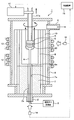
図1は、本開示の第1実施形態にかかる結晶製造装置の断面図であり、
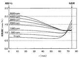
図2は、SiC単結晶の成長表面を回転させていない場合と回転速度を変化させて回転させた場合それぞれについての成長表面の各部での成長速度を表した図であり、
図3は、SiC単結晶の成長面の中心となる結晶中心と外周位置となる結晶端それぞれについて、回転速度に対する成長速度の変化を表した図であり、
図4は、成長速度とフラット度との関係を示した図であり、
図5は、本開示の第3実施形態にかかる結晶製造装置の断面図であり、
図6は、本開示の第4実施形態で説明するSiC原料ガスを導入しない状態でシャフトを高速回転させたときの種結晶のエッチング速度を示した図であり、
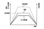
図7は、加熱容器内の温度変化に対するSiC原料ガスの供給量およびシャフトの回転速度の関係を示した図であり、
図8は、第4実施形態の変形例で説明する加熱容器内の温度変化に対するSiC原料ガスの供給量およびシャフトの回転速度の関係を示した図であり、
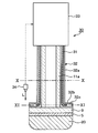
図9は、本開示の第5実施形態にかかる結晶製造装置の部分拡大断面図であり、
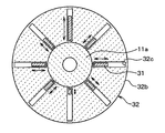
図10は、図9中のX-X断面図であり、
図11は、図9中のXI-XI断面図であり、
図12は、本開示の第6実施形態にかかる結晶製造装置の断面図であり、
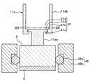
図13は、図12に示す結晶製造装置における台座近傍の拡大断面図であり、
図14は、図13のXIV-XIV線上においてシャフトの切断した断面の斜視図である。
以下、本開示の実施形態について図に基づいて説明する。なお、以下の各実施形態相互において、互いに同一もしくは均等である部分には、同一符号を付して説明を行う。
(第1実施形態)
以下、本開示の実施形態について図に基づいて説明する。なお、以下の各実施形態相互において、互いに同一もしくは均等である部分には、同一符号を付して説明を行う。
以下、本開示の実施形態について図に基づいて説明する。なお、以下の各実施形態相互において、互いに同一もしくは均等である部分には、同一符号を付して説明を行う。
(第1実施形態)
本開示の第1実施形態について説明する。まず、図1を参照して、本実施形態のSiC単結晶の製造方法が適用されるSiC単結晶製造装置(以下、単に結晶製造装置という)について説明する。
本開示の第1実施形態について説明する。まず、図1を参照して、本実施形態のSiC単結晶の製造方法が適用されるSiC単結晶製造装置(以下、単に結晶製造装置という)について説明する。
図1に示すように、結晶製造装置1に底部に流入口2が備えられており、この流入口2を通じて、原料ガス供給源3からのSiC原料ガス3aをキャリアガスやエッチングガスと共に導入する。また、結晶製造装置1には、上部に流出口4が備えられており、この流出口4を通じてSiC原料ガス3aのうちの未反応ガスなどを排出する。そして、結晶製造装置1は、装置内に配置したSiC単結晶基板からなる種結晶5上にSiC単結晶を成長させることにより、SiC単結晶20のインゴットを形成する。
具体的には、結晶製造装置1には、原料ガス供給源3、真空容器6、下部断熱材7、加熱容器8、台座9、外周断熱材10、回転引上機構11、第1、第2加熱装置12、13、温度測定部14、成長量および形状観測部15および制御装置16が備えられている。
原料ガス供給源3は、キャリアガスやエッチングガスと共にSiおよびCを含有するSiC原料ガス3aを流入口2より供給する。例えば、SiC原料ガス3aとしては、シラン、四塩化珪素等のシラン系ガスとプロパン等の炭化水素系ガスの混合ガスを用いている。
真空容器6は、石英ガラスなどで構成され、中空円筒状の部材で構成されている。真空容器6は、キャリアガスやエッチングガスおよびSiC原料ガス3aの導入導出が行え、かつ、結晶製造装置1の他の構成要素を収容すると共に、その収容している内部空間の圧力を真空引きすることにより減圧できる構造とされている。この真空容器6の底部にSiC原料ガス3aなどの流入口2が設けられ、上部(具体的には側壁の上方位置)にSiC原料ガス3aなどの流出口4が設けられている。
下部断熱材7は、円筒形状を為しており、真空容器6に対して同軸的に配置され、中空部によりSiC原料ガス3aなどが導入されるガス導入管7aを構成している。下部断熱材7は、例えば黒鉛や表面をTaC(炭化タンタル)、NbC(炭化ニオブ)、ZrC(炭化ジルコニウム)などの高融点金属炭化物にてコーティングした黒鉛などで構成されることで、熱エッチングが抑制できるようにしてある。なお、下部断熱材7は温度測定用の穴を有してもよい。
加熱容器8は、種結晶5の表面にSiC単結晶20を成長させる反応室を構成しており、例えば黒鉛や表面をTaC、NbC、ZrCなどの高融点金属炭化物にてコーティングした黒鉛またはTaC、NbC、ZrCなどの高融点金属炭化物などで構成されることで、熱エッチングが抑制できるようにしてある。この加熱容器8は、台座9を囲むように、台座9に対してSiC原料ガス3aの流動方向の上流側より下流側まで配置されている。この加熱容器8により、流入口2から供給されたSiC原料ガス3aを種結晶5に導くまでに、SiC原料ガス3aに含まれたパーティクルを排除しつつ、SiC原料ガス3aを加熱分解している。
具体的には、加熱容器8は、中空円筒状部材を有した構造とされ、本実施形態の場合は有底円筒状部材で構成されている。加熱容器8には、底部に下部断熱材7の中空部と連通させられるガス導入口8aが備えられ、下部断熱材7の中空部を通過してきたSiC原料ガス3aがガス導入口8aを通じて加熱容器8内に導入される。
台座9は、加熱容器8の中心軸と同軸的に配置された円盤状部材であり、例えば黒鉛や表面をTaC、NbC、ZrCなどの高融点金属炭化物にてコーティングした黒鉛などまたはTaC、NbC、ZrCなどの高融点金属炭化物で構成されることで、熱エッチングが抑制できるようにしてある。この台座9に、種結晶5が貼り付けられ、種結晶5の表面にSiC単結晶20を成長させる。
外周断熱材10は、加熱容器8や台座9の外周を囲むことで、加熱容器8とそれよりも外周側とを断熱する。本実施形態の場合、外周断熱材10は、例えば円筒形状で構成されており、真空容器6および加熱容器8に対して同軸的に配置されている。この外周断熱材10も、例えば黒鉛や表面をTaC、NbC、ZrCなどの高融点金属炭化物にてコーティングした黒鉛などで構成されることで、熱エッチングが抑制できるようにしてある。
回転引上機構11は、ギヤやモータなどを備えた機構を有し、シャフト11aを例えば一定トルクで回転させつつ、シャフト11aの引上げを行う。シャフト11aは、一端が台座9のうちの種結晶5の貼付面と反対側の面に接続されており、他端が回転引上機構11の本体に接続されている。このシャフト11aも、例えば黒鉛や表面をTaCなどの高融点金属炭化物にてコーティングした黒鉛などで構成されることで、熱エッチングが抑制できるようにしてある。このような構成により、シャフト11aと共に台座9、種結晶5およびSiC単結晶20の回転および引き上げが行え、SiC単結晶20の成長表面が所望の温度分布となるようにしつつ、SiC単結晶20の成長に伴って、その成長量に応じた引き上げ量に調整できる。また、SiC単結晶20の成長表面を回転させることができる。
第1、第2加熱装置12、13は、誘導加熱用コイルやヒータによって構成され、真空容器6の周囲を囲むように配置されている。これら第1、第2加熱装置12、13は、それぞれ独立して温度制御できるように構成されている。このため、より細やかな温度制御を行うことができる。第1加熱装置12は、加熱容器8の下方と対応した位置に配置されている。第2加熱装置13は、台座9と対応した位置に配置されている。このような配置とされているため、第1、第2加熱装置12、13を制御することにより、SiC単結晶20の成長表面の温度分布をSiC単結晶20の成長に適した温度に調整できる。
成長量および形状観測部15は、SiC単結晶20の成長量と成長表面の形状の観測を行う。成長量および形状観測部15は、例えばX線照射器などにより構成され、加熱容器8や外周断熱材10の外側からSiC単結晶20の成長表面に対してX照射を行うことによって、成長表面の形状を観測し、その観測結果に応じた情報を制御装置16にフィードバックしている。
温度測定部14は、SiC単結晶20の成長表面の温度や成長表面内での温度分布の測定を行う。温度測定部14は、放射温度計およびCCDカメラなどにより構成され、本実施形態の場合には、流入口2やガス導入管7aを通じてSiC単結晶20の成長表面の各所の温度を測定し、その測定結果に応じた情報を制御装置16にフィードバックしている。なお、ここでは温度測定部14を流入口2側に配置する場合を例に挙げているが、加熱容器8や外周断熱材10に測定用窓を形成し、その測定用窓を通じてSiC単結晶20の成長表面の各所の温度を測定できるようにしても良い。
制御装置16は、成長量および形状観測部15や温度測定部14から送られてくる情報に基づいて、回転引上機構11によるシャフト11aの回転速度および引上量の制御を行う。具体的には、制御装置16は、成長量および形状観測部15での観測結果に基づいてSiC単結晶20の各所での成長速度(または成長量)を測定し、それに基づいてシャフト11aの回転速度と引き上げ量を制御する。また制御装置16は、温度測定部14での測定結果に基づいてSiC単結晶20の成長表面の温度や温度分布が結晶成長に適した値になるように第1、第2加熱装置12、13を調整し、温度や温度分布により結晶形状を予測し回転速度と引き上げ量を制御する。また、温度分布により結晶形状を予測し、回転速度を制御する。
このような構造により、本実施形態にかかる結晶製造装置1が構成されている。続いて、本実施形態にかかる結晶製造装置1を用いたSiC単結晶20の製造方法について説明する。
まず、台座9に種結晶5を取り付けたのち、第1、第2加熱装置12、13を制御し、所望の温度分布を付ける。具体的には、種結晶5の表面においてSiC原料ガス3aが表面反応により結晶化されることでSiC単結晶が成長しつつ、加熱容器8内において結晶化レートよりも昇華レートの方が高くなる温度となるようにする。
また、真空容器6を所望圧力にしつつ、必要に応じてArやHeなどの不活性ガスによるキャリアガスやH2やHClなどのエッチングガスを導入しながら原料ガス導入管7aを通じてSiC原料ガス3aを導入する。これにより、図1中の矢印Aで示したように、SiC原料ガス3aが流動し、種結晶5に供給されてSiC単結晶20を成長させることができる。
このとき、成長量および形状観測部15および温度測定部14の観測および測定結果を制御装置16に入力し、その結果に基づいて制御装置16に回転引上機構11、第1、第2加熱装置12、13を制御させる。具体的には、制御装置16では、成長量および形状観測部15の観測結果に基づいてSiC単結晶20の成長量と成長表面の形状を観測し、SiC単結晶20の各所での成長速度を測定すると共に、その成長速度に基づいてシャフト11aの回転速度および引き上げ量を制御する。また制御装置16では、温度測定部14の測定結果に基づいてSiC単結晶20の成長表面の各所の温度を測定し、SiC単結晶20の成長表面の温度や温度分布が結晶成長に適した値になるように第1、第2加熱装置12、13を調整し、温度や温度分布により結晶形状を予測し回転速度と引き上げ量を制御する。
従来では、SiC単結晶の成長表面へのガス供給量の均一化およびSiC単結晶とその周囲に生成されるSiC多結晶との固着防止のためにSiC単結晶を回転させているが、回転速度は非常に遅い一定速度(5rpm程度)とされている。しかしながら、このようにSiC単結晶の成長表面を低速回転させても、単にガス供給量の均一化およびSiC単結晶とSiC多結晶との固着防止を実現できるだけである。これに対して、本発明者らは、SiC単結晶20の成長表面を高速回転させると、その回転速度に応じて成長速度が変化することを見出した。これに基づき、本実施形態では、SiC単結晶20の成長過程においてはシャフト11aを高速回転させることでSiC単結晶20の成長表面を高速回転させ、その回転によってSiC単結晶20の成長速度および成長表面の形状を制御する。以下、この制御方法について、図2~図3を参照して説明する。
SiC単結晶20の成長表面を高速回転させると、SiC原料ガス3aが形成する成長表面付近の境界層、つまりSiC原料ガス3aの原料濃度の薄い部分と濃い部分の境界となる濃度勾配の大きな層の厚みを薄くできる。このため、SiC単結晶20の成長表面から原料濃度の濃い部分までの距離が短くなり、SiC原料ガス3a内の原料が成長のために消費されても直ぐに次の原料が供給されるようになって、原料の新陳代謝を促進させることが可能になる。これにより、SiC単結晶20の成長速度を向上させることが可能になる。また、SiC単結晶20の成長表面の回転速度に応じて、SiC単結晶20の成長表面内において成長速度が異なっており、それに応じて成長表面の形状も変化する。このため、SiC単結晶20の成長表面の回転速度を調整することで、凸面成長もしくはフラット成長となるように制御できる。
SiC単結晶20の回転数を変化させた場合のSiC単結晶20の径方向に対する成長速度分布についてシミュレーションを行った。シミュレーションでは、6インチ(半径75mm程度)の種結晶5上にSiC単結晶20を成長させ、成長中にSiC単結晶20の成長表面を回転させていない場合と500rpm~5000rpmで回転速度を変化させた場合それぞれについて成長表面の成長速度を調べた。また、SiC単結晶20の成長面の中心となる結晶中心と外周位置となる結晶端それぞれについて、回転速度に対する成長速度の変化について調べた。その結果を示したのが図2~図3である。
図2および図3に示されるように、SiC単結晶20の成長表面を回転させていない場合にはSiC単結晶20の成長表面のうちの結晶中心の方が結晶端(外縁部)よりも成長速度が小さくなる。このような状況で成長を続けると、SiC単結晶20の成長表面の形状が凹形状、つまり結晶中心の方が結晶端よりも凹んだ凹面成長になる。一方、SiC単結晶20の結晶表面を回転させた場合には、SiC単結晶20の回転速度が速くなるほど、結晶中心での成長速度が結晶端での成長速度よりも大きくなる。このような状況で成長を続けると、SiC単結晶20の成長表面の形状が凸形状、つまり結晶中心の方が結晶端よりも突き出した凸面成長になる。したがって、SiC単結晶20の成長表面の回転速度に基づいて、成長表面の形状や成長速度を制御することが可能であることが判る。
また、SiC単結晶20の成長速度は、図3に示すようにSiC単結晶20の成長表面を回転させていない場合と比較して、結晶中心では大きくなるが結晶端では変化が無い。より詳しくは結晶端から所定距離内側(5mm程度内側)の位置では、SiC単結晶20の成長表面の回転の有無および回転速度に拘わらず成長速度が等しくなる。この成長速度が等しくなる位置(r=70mm)を等成長位置として、この等成長位置でのSiC単結晶20の成長速度に対する結晶中心の成長速度を正規化したものを成長表面の平坦度合を示したフラット度と定義すると、回転速度とフラット度との関係は図4のように表される。ここでは、SiC単結晶20の成長表面がフラット、凸形状、凹形状それぞれの場合において、回転速度とフラット度との関係を調べてある。また、フラット度は、結晶中心からの距離をr(結晶中心はr=0mm、結晶端はr=70mm)とし、成長速度をGr(r)として、結晶中心と結晶端との成長速度の差(Gr(0)-Gr(70))を結晶中心の成長速度Gr(0)で割った値としてある。
フラット度は、SiC単結晶20の結晶中心と結晶端での成長速度が等しくなるときに0となり、結晶中心の方が結晶端よりも成長速度が大きいと正の値(凸形状)、その逆になる場合には負の値(凹形状)になる。図4から判るように、SiC単結晶20の成長表面がフラットの状態においては、回転速度が1000rpm以下でフラット度が0になる。このため、SiC単結晶20の成長表面をフラット化もしくは凸面化するには比較的小さな回転速度でSiC単結晶20の成長表面を回転させれば良い。また、SiC単結晶20の成長表面が凸形状の状態においては、回転速度が500rpmを超えるとフラット度が0もしくは正の値になる。この場合には、フラットの場合よりも低い回転数でSiC単結晶20の成長表面を回転させても、フラット化もしくは凸面化することができる。さらに、SiC単結晶20の成長表面が凹形状の状態においては、回転速度が1000rpmよりも大きいとフラット度が0もしくは正の値になる。この場合には、フラットの場合よりも高い回転数でSiC単結晶20の成長表面を回転させないと、フラット化もしくは凸面化することができない。
このため、例えばSiC単結晶20の成長表面を1000rpmの回転速度で回転させながらSiC単結晶20を成長させ、成長量および形状観測部15での観測結果に基づいて結晶中心および結晶端の成長速度を求める。また、結晶端の成長速度が所定の成長速度(例えば単位時間当たりの成長速度1mm/h)のときの結晶中心での成長速度の狙い値を中心とした閾範囲(例えば1.2±αmm/h)を設定する。そして、結晶中心での成長速度が閾範囲内であるか、その閾範囲の上限値よりも大きいか、もしくは閾範囲の下限値より小さいかを判定する。そして、結晶中心での成長速度が閾範囲内であればフラットであることから同じ回転速度のままに制御する。また、閾範囲の上限値よりも大きければ凸面成長であることから、回転速度を維持することで凸面成長を維持するか、もしくは、回転速度を低下させることでフラット化させる。例えば、回転速度を500rpm未満に下げることで凹面化させ、徐々にフラットに近づけられるようにする。さらに、閾範囲の下限値よりも小さければ凹面成長であることから、回転速度を上昇させることで徐々にフラットに近づけたり、凸面成長させられるようにする。このようにして、SiC単結晶20の成長表面がフラットもしくは凸面状となるように制御することができる。なお、ここでは閾範囲をある程度幅を持った範囲としたが、狙い値のみとしても良い。
以上説明したように、所定の回転速度でSiC単結晶20の成長表面を高速回転させつつ、SiC単結晶20が凸面成長しているか凹面成長しているかに基づいて、回転速度を制御するようにしている。具体的には、SiC単結晶20の結晶中心での成長速度が狙い値を中心とした閾範囲の上限値よりも大きければ回転速度を維持もしくは低下させ、閾範囲の下限値よりも小さければ回転速度を上昇させる。このように、SiC単結晶20の成長表面を高速回転させることによって高速成長を可能としつつ、成長速度に応じて回転速度を制御することでSiC単結晶20が凸面成長もしくはフラット成長となるように制御できる。これにより、高品質なSiC単結晶20をさらに高速成長させることが可能となる。
(第2実施形態)
本開示の第2実施形態について説明する。本実施形態は、第1実施形態に対してSiC単結晶20の成長表面の回転速度の制御方法を変更したものであり、その他については第1実施形態と同様であるため、第1実施形態と異なる部分についてのみ説明する。
本開示の第2実施形態について説明する。本実施形態は、第1実施形態に対してSiC単結晶20の成長表面の回転速度の制御方法を変更したものであり、その他については第1実施形態と同様であるため、第1実施形態と異なる部分についてのみ説明する。
第1実施形態では、SiC単結晶20の成長表面のうちの結晶中心での成長速度が成長表面の形状を表していることから、成長速度に基づいてSiC単結晶20の成長表面の回転速度を制御したが、成長表面の結晶形状に基づいて制御するようにしても良い。すなわち、SiC単結晶20の成長表面の結晶形状が凸形状である場合には、回転速度を維持することで凸面成長を維持するか、もしくは、回転速度を低下させることでフラット化させる。また、SiC単結晶20の成長表面の結晶形状が凹形状である場合には、回転速度を上昇させることでフラット化させたり、凸面成長させられるようにする。このように、SiC単結晶20の成長表面の結晶形状に基づいてSiC単結晶20の成長表面の回転速度を制御するようにしても、第1実施形態と同様の効果を得ることができる。
なお、SiC単結晶20の成長表面の形状については成長量および形状観測部15によって観測されることから、この形状観測部15での観測結果に基づいて、SiC単結晶20の成長表面の回転速度を制御すれば良い。
(第3実施形態)
本開示の第3実施形態について説明する。本実施形態は、第1実施形態に対してSiC単結晶20の製造方法に適用される結晶製造装置1の構成を変更したものであり、その他については第1実施形態と同様であるため、第1実施形態と異なる部分についてのみ説明する。
本開示の第3実施形態について説明する。本実施形態は、第1実施形態に対してSiC単結晶20の製造方法に適用される結晶製造装置1の構成を変更したものであり、その他については第1実施形態と同様であるため、第1実施形態と異なる部分についてのみ説明する。
図5に示すように、本実施形態の結晶製造装置1では、シャフト11aにバランスウェイト11bを備えてある。具体的には、シャフト11aは図示しないシール部などによってシールされた状態で真空容器6の外部に突き出した構造とされているが、この真空装置6の外部に突き出した部分にバランスウェイト11bが備えられている。バランスウェイト11bは、シャフト11aを中心として径方向に延びる支持バー11cと、支持バー11cに対してスライド可能に構成されるウェイト部11dとを有した構成とされている。例えば支持バー11cはシャフト11aを中心として180°ずれた方向に延びるような対称な配置で取り付けられている。そして、バランスウェイト11bにおけるウェイト部11dのスライド位置、つまりウェイト部11dの周回距離rは、制御装置16によって制御可能とされている。また、シャフト11aには荷重センサとしてのロードセル11eが備えられ、シャフト11aに加わっている荷重、具体的には台座9や種結晶5およびSiC単結晶20の重さを含めたシャフト11aの重さを測定し、制御装置16にフィードバックしている。制御装置16は、上記した温度測定部14の測定結果や成長量および形状観測部15の観測結果に加えてロードセル11eでの測定結果に基づいて、バランスウェイト11bにおけるウェイト部11dのスライド位置を調整している。
上記したように、回転引上機構11では、例えばシャフト11aを一定トルクで回転させる定トルク制御によってSiC単結晶20の成長表面の回転数を制御している。このため、制御装置16によってウェイト部11dのスライド位置が調整されると、そのスライド位置に対応する周回距離rに応じてシャフト11aの回転速度を変化させられる。これに基づき、制御装置16によってウェイト部11dのスライド位置を調整することで、SiC単結晶20の成長表面の回転速度を変化させている。
具体的には、結晶が小さいSiC単結晶20の成長初期段階においては、周回距離rが大きくなるようにウェイト部11dのスライド位置を調整することで、成長速度を低くしながらより高品質な結晶となるようにする。また、SiC単結晶20が大きくなるに連れて、周回距離rが小さくなるようにウェイト部11dのスライド位置を径方向内方に移動させ、成長速度を上昇させてSiC単結晶20を高速成長させるようにする。そして、成長速度が狙い値となるようにSiC単結晶20の成長表面を高速回転させつつ、例えば第1実施形態と同様に、成長速度が閾範囲の上限値よりも大きければ回転速度を維持もしくは低下させ、閾範囲の下限値よりも小さければ回転速度を上昇させる。または、第2実施形態と同様に、SiC単結晶20の成長表面の形状が凸形状であればSiC単結晶20の成長表面の回転速度を維持もしくは低下させ、凹形状であれば回転速度を上昇させる。
このように、シャフト11aに対してバランスウェイト11bを備えつつ、ウェイト部11dのスライド位置を調整することで、SiC単結晶20の成長に合わせて成長表面の回転速度を調整できる。また、SiC単結晶20の成長速度もしくは成長表面の形状に合わせてSiC単結晶20の成長表面の回転速度を調整することも可能となる。
(第4実施形態)
本開示の第4実施形態について説明する。本実施形態は、第1~第3実施形態に対してSiC単結晶20のSiC原料ガス3aの導入方法を変更したものであり、その他については第1~第3実施形態と同様であるため、第1~第3実施形態と異なる部分についてのみ説明する。
本開示の第4実施形態について説明する。本実施形態は、第1~第3実施形態に対してSiC単結晶20のSiC原料ガス3aの導入方法を変更したものであり、その他については第1~第3実施形態と同様であるため、第1~第3実施形態と異なる部分についてのみ説明する。
本実施形態では、SiC単結晶20の成長開始時と成長中および成長終了時において、SiC原料ガス3aの導入量を変えるようにする。
SiC単結晶20を高速成長させるためには、加熱容器8内を高温としつつ種結晶5が低温となるような温度分布とすることが望ましいが、図6に示すようにSiC原料ガス3aを導入しない状態でシャフト11aを高速回転させると、種結晶5がエッチングされる。種結晶5のエッチング速度はシャフト11aの回転数に応じて変化し、回転数が高いほどエッチング速度が大きくなる。このため、SiC原料ガス3aを加熱分解して原料が供給される前の段階、つまりSiC単結晶20の成長初期の段階となる加熱容器8の昇温中の期間には、昇温後となる成長中の温度よりもシャフト11aの回転速度を低下させる方が好ましい。また、SiC単結晶20の成長終了時に再び加熱容器8を降温する際にも、シャフト11aを高速回転させた状態にするとSiC単結晶20の表面がエッチングされてしまうため、成長中の温度よりもシャフト11aの回転速度を低下させる方が好ましい。
したがって、本実施形態では、図7に示すように、加熱容器8を昇温中の期間には、シャフト11aを回転させないもしくは従来の低速回転となるようにし、昇温が完了して成長温度に達するとシャフト11aを高速回転させるようにしている。具体的には、SiC単結晶20の結晶中心での成長速度が狙い値となる回転速度でシャフト11aを高速回転させるようもしくは従来の低速回転となるようにする。そして、SiC単結晶20の成長が終了して加熱容器8を降温させる際には、再びシャフト11aの回転を停止する。このようにすることで、加熱容器8の昇温中もしくは降温中に、種結晶5やSiC単結晶20がエッチングされてしまうことを抑制することが可能となる。
(第4実施形態の変形例)
上記第4実施形態では、加熱容器8を昇温中や降温中の期間にはシャフト11aを回転させないようにしたが、図8に示すように、加熱容器8の昇温中や降温中には、加熱容器8内の温度に比例してシャフト11aの回転速度を変化させるようにしてもよい。このようにしても、SiC原料ガス3aの供給が行われていない期間中のシャフト11aの回転速度を抑えることができるため、第4実施形態と同様の効果を得ることができる。
上記第4実施形態では、加熱容器8を昇温中や降温中の期間にはシャフト11aを回転させないようにしたが、図8に示すように、加熱容器8の昇温中や降温中には、加熱容器8内の温度に比例してシャフト11aの回転速度を変化させるようにしてもよい。このようにしても、SiC原料ガス3aの供給が行われていない期間中のシャフト11aの回転速度を抑えることができるため、第4実施形態と同様の効果を得ることができる。
さらに、図8に示すようにシャフト11aの回転速度を加熱容器8内の温度に比例して変化させる場合において、SiC原料ガス3aを成長温度に達する前から導入しつつ、その導入量を回転速度に比例して変化させるようにすると好ましい。このようにすれば、シャフト11aの回転速度に応じてSiC原料ガス3aを種結晶5もしくは成長後のSiC単結晶20の表面に供給できることから、これらの回転に伴って表面がエッチングされてしまうことを更に抑制することが可能となる。
(第5実施形態)
本開示の第5実施形態について説明する。本実施形態は、第1~第4実施形態に対してシャフト11aの回転中心のずれ(芯ぶれ)を抑制できるようにしたものであり、その他については第1~第4実施形態と同様であるため、第1~第4実施形態と異なる部分についてのみ説明する。
本開示の第5実施形態について説明する。本実施形態は、第1~第4実施形態に対してシャフト11aの回転中心のずれ(芯ぶれ)を抑制できるようにしたものであり、その他については第1~第4実施形態と同様であるため、第1~第4実施形態と異なる部分についてのみ説明する。
図9~図11に示すように、本実施形態の結晶製造装置1には、芯ぶれ調整機構30が備えられている。芯ぶれ調整機構30は、複数本のワイヤ31、通路構成部材32、ワイヤ制御機構33および偏心センサ34を有した構成とされている。
複数本のワイヤ31は、後述するように通路構成部材32に備えられた通路32c内における出し入れ量が調整されることで、バランスウェイトとしての役割を果たす。例えばワイヤ31は、高融点金属などで構成されている。
通路構成部材32は、シャフト11aの外周から台座9の裏面に至るように、つまりシャフト11aの外周を囲む円筒部32aと、台座9の裏面において径方向にフランジ状に張り出したホイール部32bとを有した構造とされている。これら各部32a、32bは、例えば黒鉛や表面をTaC、NbC、ZrCなどの高融点金属炭化物にてコーティングした黒鉛などで構成されることで、熱エッチングが抑制できるようにしてある。通路構成部材32の内部にはワイヤ31の数に対応した数の通路32cが備えられている。各通路32cは、シャフト11aの中心軸を中心として周方向に等間隔に配置されており、シャフト11aの周囲においてはシャフト11aの軸方向に平行に伸び、台座9の裏面において径方向外方に放射状に伸びる形状とされている。このため、図11中の矢印で示したように、通路32c内における径方向へのワイヤ31の出し入れ量に応じてシャフト11aを回転させたときのワイヤ31の周回距離が変わることで、ワイヤ31がバランスウェイトとしての役割を果たすようになっている。
ワイヤ制御機構33は、偏心センサ34での検出結果に基づいて、ワイヤ31の通路32c内への出し入れ量を制御する。偏心センサ34は、台座9の裏面側、本実施形態の場合は通路構成部材32のうちのフランジ形状部分の表面から所定距離離れた位置に配置され、台座9の回転中心の偏心度合いを検出する。例えば、偏心センサ34は、シャフト11aの回転に基づいて台座9や通路構成部材32が回転させられているときの偏心センサ34から通路構成部材32のフランジ形状部分までの距離Lをモニタし、それに応じた検出信号をワイヤ制御機構33に出力する。台座9の回転中心が偏心した場合、つまり重心がずれた場合、回転時に台座9や通路構成部材32のフランジ形状部分が上下動する。このため、距離Lをモニタすることで台座9の回転中心の偏心度合いを検出できる。この検出結果に基づいて、ワイヤ制御機構33が通路32c内へのワイヤ31の出し入れ量を調整することで、台座9の重心を調整し、回転中心の偏心を抑制することが可能になっている。
なお、本実施形態では、ワイヤ31および通路32cを8本ずつ備えるようにしたが、これ以外の本数であっても良い。その場合にも、シャフト11aの軸方向から見て、ワイヤ31および通路32cを台座9の回転中心を中心軸とした軸対称に配置してあればよい。また、ここではシャフト11aの外周を囲むように円筒部32aを備えるようにしたが、シャフト11aによって円筒部32aを構成するようにしても良い。同様に、台座9によってホイール部32bを構成するようにしても良い。
このように、芯ぶれ調整機構30を備え、ワイヤ31や通路構成部材32およびワイヤ制御機構33をシャフト11aや台座9および種結晶5と共に回転させることにより、台座9の重心を調整でき、回転中心の偏心を抑制することが可能となる。これにより、SiC単結晶20の成長表面が回転に伴って変位することを抑制でき、より安定して高品質にSiC単結晶20を成長させることが可能となる。
また、台座9の裏面側は、結晶製造装置1の中でも比較的低温となる部分であることから、その位置に芯ぶれ調整機構30を備えるようにすることで、高温により芯ぶれ調整機構30の構成部品が熱エッチングされることなどを抑制できる。
(第6実施形態)
本開示の第6実施形態について説明する。本実施形態も、第1~第4実施形態に対してシャフト11aの回転中心のずれ(芯ぶれ)を抑制できるようにしたものであり、その他については第1~第4実施形態と同様であるため、第1~第4実施形態と異なる部分についてのみ説明する。
本開示の第6実施形態について説明する。本実施形態も、第1~第4実施形態に対してシャフト11aの回転中心のずれ(芯ぶれ)を抑制できるようにしたものであり、その他については第1~第4実施形態と同様であるため、第1~第4実施形態と異なる部分についてのみ説明する。
図12に示すように、本実施形態の結晶製造装置1にも、芯ぶれ調整機構40が備えられている。芯ぶれ調整機構40は、シャフト11aに設けた軸調整機構41と、台座9の周囲に設けた回転固定部42とを有する構成とされている。
図13に示したように、軸調整機構41は、シャフト11aを第1シャフト11aaおよび第2シャフト11abに分割することで構成される第1、第2シャフト11aa、11abの連結部に備えられている。この軸調整機構41により、第1シャフト11aaの中心軸を第2シャフト11abの中心軸に対して傾斜可能にする。具体的には、シャフト11aのうち台座9側を第1シャフト11aa、台座9と反対側を第2シャフト11abとし、第1、第2シャフト11aa、11abが連結されることでシャフト11aを構成している。
図13および図14に示すように、第1シャフト11aaを円柱状で構成しつつ、第1シャフト11aaのうちの第2シャフト11ab側の端部に径方向に突き出した突起部41aを備えている。突起部41aは、第1シャフト11aaの外周面において周方向に等間隔に備えられており、図14に示すように本実施形態では4箇所に備えられている。一方、第2シャフト11abのうち第1シャフト11aa側の先端には、第1シャフト11aaを挿通させつつ第1シャフト11aaを支持する支持部41bが備えられている。
支持部41bは、例えば第2シャフト11abのうちの第1シャフト11aa側において内径を縮小させることで構成される。支持部41bには、第1シャフト11aaにおける円柱状の部分での外径寸法よりも大きく、かつ、突起部41aでの外径寸法よりも小さな挿入穴41cが備えられている。また、支持部41bには、支持部41bのうち台座9と反対側の端面において挿入穴41cの内壁面において部分的に内径を拡大させた係合溝41dが形成されている。係合溝41dは、第1シャフト11aaに備えた各突起部41aそれぞれと対応する位置に形成されており、突起部41aよりも若干大きな寸法で構成されている。
そして、支持部41bの挿入穴41c内に、突起部41aが形成された端部と反対側の端部より第1シャフト11aaが上方から挿入され、係合溝41d内に各突起部41aが嵌め込まれることで、第1、第2シャフト11aa、11abが連結されている。
また、回転固定部42は、台座9の外周面と当接するコロ42aが備えられたベアリング42bによって構成されている。回転固定部42を構成する各部は、例えば黒鉛や表面をTaC、NbC、ZrCなどの高融点金属炭化物にてコーティングした黒鉛などで構成されることで、熱エッチングが抑制できるようにしてある。回転固定部42は、台座9の回転中心に設定すべき中心軸と同軸的に配置され、回転固定部42の内径、つまりコロ42aの内側の径が台座9の外径に合わせてある。本実施形態では、回転固定部42は、加熱容器8の内壁面に固定された状態とされており、台座9の外周と対応する位置から更に下方位置まで延設されている。
このような構造により、本実施形態にかかる結晶製造装置1が構成されている。このような構成においては、第1シャフト11aaが第2シャフト11abに対して遊びを持った遊嵌合状態となる。このため、第1シャフト11aaの中心軸を第2シャフト11abの中心軸に対してずらしたり、傾斜させるなど変位させることが可能となる。そして、第1シャフト11aaに取り付けられた台座9は、固定部42に備えられたコロ42aに当接した状態でシャフト11aの回転に伴って回転可能となる。したがって、台座9の回転中心を回転固定部42の中心軸に沿って固定することが可能となり、台座9の重心を調整し、回転中心の偏心を抑制することが可能となる。よって、第5実施形態と同様の効果を得ることが可能となる。
また、回転固定部42を台座9の外周と対応する位置から更に下方位置まで延設していることから、SiC単結晶20の外周を囲むように回転固定部42の内壁面を配置できる。このため、回転固定部42をガイドとして、SiC単結晶20をガイドに沿って成長させることが可能となる。
(他の実施形態)
本開示は上記した実施形態に限定されるものではなく、適宜変更が可能である。例えば、各実施形態に示した結晶製造装置1の構成部品の材質や形状、数などについては、適宜変更可能である。
本開示は上記した実施形態に限定されるものではなく、適宜変更が可能である。例えば、各実施形態に示した結晶製造装置1の構成部品の材質や形状、数などについては、適宜変更可能である。
本開示は、実施例に準拠して記述されたが、本開示は当該実施例や構造に限定されるものではないと理解される。本開示は、様々な変形例や均等範囲内の変形をも包含する。加えて、様々な組み合わせや形態、さらには、それらに一要素のみ、それ以上、あるいはそれ以下、を含む他の組み合わせや形態をも、本開示の範疇や思想範囲に入るものである。
Claims (9)
- 炭化珪素単結晶(20)を成長させる反応室を構成する加熱容器(8)内に台座(9)を配置し、
該台座(9)に種結晶(5)を貼り付け、
前記加熱容器を通じて炭化珪素の原料ガス(3a)を供給することで、前記加熱容器にて前記原料ガスを加熱分解して前記種結晶の表面に供給し、該種結晶の表面に前記炭化珪素単結晶を成長させ、
前記炭化珪素単結晶の成長速度が狙い値を中心とした閾範囲内であるか、その閾範囲の上限値よりも大きいか、もしくは閾範囲の下限値より小さいかを判定し、
前記閾範囲内であれば、種結晶の回転速度を維持し、
前記閾範囲の上限値よりも大きい場合には、前記回転速度を維持もしくは低下させ、
前記閾範囲の下限値よりも小さい場合には、前記回転速度を上昇させることを備える炭化珪素単結晶の製造方法。 - 前記種結晶の中心を中心軸として、前記台座および前記種結晶を所定の回転速度で回転させつつ、前記種結晶の表面に前記炭化珪素単結晶を成長させ、
前記炭化珪素単結晶の成長表面のうちの外周位置となる結晶端よりも該成長表面の中心となる結晶中心の方が突出している凸面成長であるか、前記結晶端よりも前記結晶中心が窪んでいる凹面成長であるかを判定し、
前記凸面成長であれば、前記回転速度を維持もしくは低下させ、
前記凹面成長であれば、前記回転速度を上昇させることをさらに備える請求項1に記載の炭化珪素単結晶の製造方法。 - 前記炭化珪素単結晶の成長表面の形状を観測し、該成長表面の形状から前記凸面成長であるか前記凹面成長であるかを判定することをさらに備える請求項2に記載の炭化珪素単結晶の製造方法。
- 前記回転速度を0~5000rpmの範囲内において制御することをさらに備える請求項1ないし3のいずれか1つに記載の炭化珪素単結晶の製造方法。
- 前記加熱容器内の温度が前記炭化珪素単結晶を成長させる成長温度に達するまでは、前記回転速度を前記成長温度の際の回転速度よりも低下させることをさらに備える請求項4に記載の炭化珪素単結晶の製造方法。
- 前記台座にシャフト(11a)を接続し、
該シャフトを一定トルクで回転させることで前記台座および前記種結晶を回転させ、
前記シャフトに該シャフトを中心として径方向に延びる支持バー(11c)と該支持バーに対してスライド可能に構成されるウェイト部(11d)とを有するバランスウェイト(11b)を配置し、前記シャフトと共に該バランスウェイトも回転させるようにし、
前記炭化珪素単結晶が大きくなるに連れて前記ウェイト部のスライド位置を前記シャフトの径方向内方に移動させることをさらに備える請求項1ないし5のいずれか1つに記載の炭化珪素単結晶の製造方法。 - 前記シャフトに、前記台座および前記種結晶の回転の中心軸を調整する芯ぶれ調整機構(30、40)を配置することをさらに備える請求項6に記載の炭化珪素単結晶の製造方法。
- 前記芯ぶれ調整機構(30)は、前記シャフトの径方向に延設された通路(32c)内にワイヤ(31)を出し入れする構成により提供され、
前記ワイヤの出し入れ量を制御することで、前記台座および前記種結晶の回転の中心軸を調整する請求項7に記載の炭化珪素単結晶の製造方法。 - 前記芯ぶれ調整機構(30)は、円盤状の前記台座の外周面に当接するコロ(42a)を備えたベアリング(42b)により提供され、
前記シャフトは、前記台座側となる第1シャフト(11aa)と前記台座と反対側となる第2シャフト(11ab)に分割され、
前記第1シャフトの中心軸を前記第2シャフトの中心軸に対して変位させることで、前記台座および前記種結晶の回転の中心軸を調整する請求項7に記載の炭化珪素単結晶の製造方法。
Applications Claiming Priority (2)
| Application Number | Priority Date | Filing Date | Title |
|---|---|---|---|
| JP2013-123800 | 2013-06-12 | ||
| JP2013123800A JP6268761B2 (ja) | 2013-06-12 | 2013-06-12 | 炭化珪素単結晶の製造方法 |
Publications (1)
| Publication Number | Publication Date |
|---|---|
| WO2014199571A1 true WO2014199571A1 (ja) | 2014-12-18 |
Family
ID=52021892
Family Applications (1)
| Application Number | Title | Priority Date | Filing Date |
|---|---|---|---|
| PCT/JP2014/002695 Ceased WO2014199571A1 (ja) | 2013-06-12 | 2014-05-22 | 炭化珪素単結晶の製造方法 |
Country Status (2)
| Country | Link |
|---|---|
| JP (1) | JP6268761B2 (ja) |
| WO (1) | WO2014199571A1 (ja) |
Cited By (1)
| Publication number | Priority date | Publication date | Assignee | Title |
|---|---|---|---|---|
| CN116497437A (zh) * | 2023-06-25 | 2023-07-28 | 通威微电子有限公司 | 一种碳化硅生长装置、生长方法和碳化硅晶体 |
Families Citing this family (4)
| Publication number | Priority date | Publication date | Assignee | Title |
|---|---|---|---|---|
| WO2017047536A1 (ja) * | 2015-09-14 | 2017-03-23 | 新日鐵住金株式会社 | SiC単結晶の製造装置、SiC単結晶の製造方法及びSiC単結晶材 |
| KR101789297B1 (ko) * | 2016-05-25 | 2017-10-23 | 주식회사 티씨케이 | 단결정 성장장치 및 이의 제어방법 |
| JP7255089B2 (ja) * | 2018-05-25 | 2023-04-11 | 株式会社デンソー | 炭化珪素単結晶製造装置および炭化珪素単結晶の製造方法 |
| KR102479333B1 (ko) * | 2018-10-11 | 2022-12-19 | 주식회사 엘지화학 | 실리콘카바이드 단결정의 제조 장치 및 제조 방법 |
Citations (2)
| Publication number | Priority date | Publication date | Assignee | Title |
|---|---|---|---|---|
| JP2003183098A (ja) * | 2001-12-18 | 2003-07-03 | Denso Corp | SiC単結晶の製造方法及びSiC単結晶の製造装置 |
| JP2012131679A (ja) * | 2010-12-24 | 2012-07-12 | Nippon Steel Corp | 炭化珪素単結晶インゴットの製造装置 |
Family Cites Families (1)
| Publication number | Priority date | Publication date | Assignee | Title |
|---|---|---|---|---|
| JPH05208900A (ja) * | 1992-01-28 | 1993-08-20 | Nisshin Steel Co Ltd | 炭化ケイ素単結晶の成長装置 |
-
2013
- 2013-06-12 JP JP2013123800A patent/JP6268761B2/ja active Active
-
2014
- 2014-05-22 WO PCT/JP2014/002695 patent/WO2014199571A1/ja not_active Ceased
Patent Citations (2)
| Publication number | Priority date | Publication date | Assignee | Title |
|---|---|---|---|---|
| JP2003183098A (ja) * | 2001-12-18 | 2003-07-03 | Denso Corp | SiC単結晶の製造方法及びSiC単結晶の製造装置 |
| JP2012131679A (ja) * | 2010-12-24 | 2012-07-12 | Nippon Steel Corp | 炭化珪素単結晶インゴットの製造装置 |
Cited By (2)
| Publication number | Priority date | Publication date | Assignee | Title |
|---|---|---|---|---|
| CN116497437A (zh) * | 2023-06-25 | 2023-07-28 | 通威微电子有限公司 | 一种碳化硅生长装置、生长方法和碳化硅晶体 |
| CN116497437B (zh) * | 2023-06-25 | 2023-08-18 | 通威微电子有限公司 | 一种碳化硅生长装置和生长方法 |
Also Published As
| Publication number | Publication date |
|---|---|
| JP6268761B2 (ja) | 2018-01-31 |
| JP2014240336A (ja) | 2014-12-25 |
Similar Documents
| Publication | Publication Date | Title |
|---|---|---|
| JP6268761B2 (ja) | 炭化珪素単結晶の製造方法 | |
| JP6118425B2 (ja) | 単結晶インゴット製造装置及び方法 | |
| JP6844560B2 (ja) | シリコン融液の対流パターン制御方法、シリコン単結晶の製造方法、および、シリコン単結晶の引き上げ装置 | |
| WO2020039553A1 (ja) | シリコン単結晶の育成方法 | |
| KR101385997B1 (ko) | 단결정 제조장치 및 단결정 제조방법 | |
| KR101862157B1 (ko) | 단결정 실리콘 잉곳 제조 방법 및 장치 | |
| JP6729470B2 (ja) | 単結晶の製造方法及び装置 | |
| JP6977619B2 (ja) | シリコン単結晶の酸素濃度推定方法、およびシリコン単結晶の製造方法 | |
| US7582160B2 (en) | Silicone single crystal production process | |
| JP2010155726A (ja) | 単結晶の育成方法及びその方法で育成された単結晶 | |
| CN109415843B (zh) | 单晶硅的制造方法 | |
| US7208042B2 (en) | Method of manufacturing silicon single crystal and silicon single crystal manufactured by the method | |
| WO2019167986A1 (ja) | シリコン融液の対流パターン制御方法、および、シリコン単結晶の製造方法 | |
| JP2020114802A (ja) | シリコン単結晶の製造方法 | |
| JP5482547B2 (ja) | シリコン単結晶の製造方法 | |
| JPWO2020174598A1 (ja) | シリコン融液の対流パターン制御方法、および、シリコン単結晶の製造方法 | |
| JP2009286651A (ja) | 石英ガラスルツボとその製造方法 | |
| JP7052694B2 (ja) | シリコン単結晶の製造方法 | |
| JP2018043904A (ja) | シリコン単結晶の製造方法 | |
| JP7249913B2 (ja) | シリコン単結晶の製造方法 | |
| JP2019210199A (ja) | シリコン単結晶の製造方法 | |
| JP5929825B2 (ja) | シリコン単結晶の製造方法 | |
| JP5333396B2 (ja) | 単結晶の製造方法及び単結晶製造装置 | |
| JP7853043B2 (ja) | 高品質の半導体単結晶を製造するためのシステム、および高品質の半導体単結晶を製造する方法 | |
| JP6214038B2 (ja) | 窒化アルミニウム単結晶の製造方法 |
Legal Events
| Date | Code | Title | Description |
|---|---|---|---|
| 121 | Ep: the epo has been informed by wipo that ep was designated in this application |
Ref document number: 14811287 Country of ref document: EP Kind code of ref document: A1 |
|
| NENP | Non-entry into the national phase |
Ref country code: DE |
|
| 122 | Ep: pct application non-entry in european phase |
Ref document number: 14811287 Country of ref document: EP Kind code of ref document: A1 |