WO2014199409A1 - ウェットティッシュ包装体 - Google Patents
ウェットティッシュ包装体 Download PDFInfo
- Publication number
- WO2014199409A1 WO2014199409A1 PCT/JP2013/003637 JP2013003637W WO2014199409A1 WO 2014199409 A1 WO2014199409 A1 WO 2014199409A1 JP 2013003637 W JP2013003637 W JP 2013003637W WO 2014199409 A1 WO2014199409 A1 WO 2014199409A1
- Authority
- WO
- WIPO (PCT)
- Prior art keywords
- wet tissue
- bag
- resistance
- outlet frame
- opening
- Prior art date
Links
Images


Classifications
-
- A—HUMAN NECESSITIES
- A47—FURNITURE; DOMESTIC ARTICLES OR APPLIANCES; COFFEE MILLS; SPICE MILLS; SUCTION CLEANERS IN GENERAL
- A47K—SANITARY EQUIPMENT NOT OTHERWISE PROVIDED FOR; TOILET ACCESSORIES
- A47K10/00—Body-drying implements; Toilet paper; Holders therefor
- A47K10/24—Towel dispensers, e.g. for piled-up or folded textile towels; Toilet-paper dispensers; Dispensers for piled-up or folded textile towels provided or not with devices for taking-up soiled towels as far as not mechanically driven
- A47K10/32—Dispensers for paper towels or toilet-paper
- A47K10/42—Dispensers for paper towels or toilet-paper dispensing from a store of single sheets, e.g. stacked
- A47K10/421—Dispensers for paper towels or toilet-paper dispensing from a store of single sheets, e.g. stacked dispensing from the top of the dispenser
- A47K10/423—Dispensers for paper towels or toilet-paper dispensing from a store of single sheets, e.g. stacked dispensing from the top of the dispenser with hold-down means riding on the top of the stack, e.g. a press plate with dispensing opening
-
- B—PERFORMING OPERATIONS; TRANSPORTING
- B65—CONVEYING; PACKING; STORING; HANDLING THIN OR FILAMENTARY MATERIAL
- B65D—CONTAINERS FOR STORAGE OR TRANSPORT OF ARTICLES OR MATERIALS, e.g. BAGS, BARRELS, BOTTLES, BOXES, CANS, CARTONS, CRATES, DRUMS, JARS, TANKS, HOPPERS, FORWARDING CONTAINERS; ACCESSORIES, CLOSURES, OR FITTINGS THEREFOR; PACKAGING ELEMENTS; PACKAGES
- B65D51/00—Closures not otherwise provided for
- B65D51/18—Arrangements of closures with protective outer cap-like covers or of two or more co-operating closures
-
- B—PERFORMING OPERATIONS; TRANSPORTING
- B65—CONVEYING; PACKING; STORING; HANDLING THIN OR FILAMENTARY MATERIAL
- B65D—CONTAINERS FOR STORAGE OR TRANSPORT OF ARTICLES OR MATERIALS, e.g. BAGS, BARRELS, BOTTLES, BOXES, CANS, CARTONS, CRATES, DRUMS, JARS, TANKS, HOPPERS, FORWARDING CONTAINERS; ACCESSORIES, CLOSURES, OR FITTINGS THEREFOR; PACKAGING ELEMENTS; PACKAGES
- B65D51/00—Closures not otherwise provided for
- B65D51/24—Closures not otherwise provided for combined or co-operating with auxiliary devices for non-closing purposes
- B65D51/26—Closures not otherwise provided for combined or co-operating with auxiliary devices for non-closing purposes with means for keeping contents in position, e.g. resilient means
-
- B—PERFORMING OPERATIONS; TRANSPORTING
- B65—CONVEYING; PACKING; STORING; HANDLING THIN OR FILAMENTARY MATERIAL
- B65D—CONTAINERS FOR STORAGE OR TRANSPORT OF ARTICLES OR MATERIALS, e.g. BAGS, BARRELS, BOTTLES, BOXES, CANS, CARTONS, CRATES, DRUMS, JARS, TANKS, HOPPERS, FORWARDING CONTAINERS; ACCESSORIES, CLOSURES, OR FITTINGS THEREFOR; PACKAGING ELEMENTS; PACKAGES
- B65D75/00—Packages comprising articles or materials partially or wholly enclosed in strips, sheets, blanks, tubes, or webs of flexible sheet material, e.g. in folded wrappers
- B65D75/52—Details
- B65D75/58—Opening or contents-removing devices added or incorporated during package manufacture
- B65D75/5861—Spouts
- B65D75/5872—Non-integral spouts
- B65D75/5877—Non-integral spouts connected to a planar surface of the package wall
-
- B—PERFORMING OPERATIONS; TRANSPORTING
- B65—CONVEYING; PACKING; STORING; HANDLING THIN OR FILAMENTARY MATERIAL
- B65D—CONTAINERS FOR STORAGE OR TRANSPORT OF ARTICLES OR MATERIALS, e.g. BAGS, BARRELS, BOTTLES, BOXES, CANS, CARTONS, CRATES, DRUMS, JARS, TANKS, HOPPERS, FORWARDING CONTAINERS; ACCESSORIES, CLOSURES, OR FITTINGS THEREFOR; PACKAGING ELEMENTS; PACKAGES
- B65D75/00—Packages comprising articles or materials partially or wholly enclosed in strips, sheets, blanks, tubes, or webs of flexible sheet material, e.g. in folded wrappers
- B65D75/52—Details
- B65D75/58—Opening or contents-removing devices added or incorporated during package manufacture
- B65D75/5894—Preformed openings provided in a wall portion and covered by a separate removable flexible element
-
- B—PERFORMING OPERATIONS; TRANSPORTING
- B65—CONVEYING; PACKING; STORING; HANDLING THIN OR FILAMENTARY MATERIAL
- B65D—CONTAINERS FOR STORAGE OR TRANSPORT OF ARTICLES OR MATERIALS, e.g. BAGS, BARRELS, BOTTLES, BOXES, CANS, CARTONS, CRATES, DRUMS, JARS, TANKS, HOPPERS, FORWARDING CONTAINERS; ACCESSORIES, CLOSURES, OR FITTINGS THEREFOR; PACKAGING ELEMENTS; PACKAGES
- B65D83/00—Containers or packages with special means for dispensing contents
- B65D83/08—Containers or packages with special means for dispensing contents for dispensing thin flat articles in succession
- B65D83/0805—Containers or packages with special means for dispensing contents for dispensing thin flat articles in succession through an aperture in a wall
-
- A—HUMAN NECESSITIES
- A47—FURNITURE; DOMESTIC ARTICLES OR APPLIANCES; COFFEE MILLS; SPICE MILLS; SUCTION CLEANERS IN GENERAL
- A47K—SANITARY EQUIPMENT NOT OTHERWISE PROVIDED FOR; TOILET ACCESSORIES
- A47K10/00—Body-drying implements; Toilet paper; Holders therefor
- A47K10/24—Towel dispensers, e.g. for piled-up or folded textile towels; Toilet-paper dispensers; Dispensers for piled-up or folded textile towels provided or not with devices for taking-up soiled towels as far as not mechanically driven
- A47K10/32—Dispensers for paper towels or toilet-paper
- A47K2010/3266—Wet wipes
-
- B—PERFORMING OPERATIONS; TRANSPORTING
- B65—CONVEYING; PACKING; STORING; HANDLING THIN OR FILAMENTARY MATERIAL
- B65D—CONTAINERS FOR STORAGE OR TRANSPORT OF ARTICLES OR MATERIALS, e.g. BAGS, BARRELS, BOTTLES, BOXES, CANS, CARTONS, CRATES, DRUMS, JARS, TANKS, HOPPERS, FORWARDING CONTAINERS; ACCESSORIES, CLOSURES, OR FITTINGS THEREFOR; PACKAGING ELEMENTS; PACKAGES
- B65D2251/00—Details relating to container closures
- B65D2251/0003—Two or more closures
- B65D2251/0006—Upper closure
- B65D2251/0018—Upper closure of the 43-type
- B65D2251/0021—Upper closure of the 43-type of the B65D43/16-type
-
- B—PERFORMING OPERATIONS; TRANSPORTING
- B65—CONVEYING; PACKING; STORING; HANDLING THIN OR FILAMENTARY MATERIAL
- B65D—CONTAINERS FOR STORAGE OR TRANSPORT OF ARTICLES OR MATERIALS, e.g. BAGS, BARRELS, BOTTLES, BOXES, CANS, CARTONS, CRATES, DRUMS, JARS, TANKS, HOPPERS, FORWARDING CONTAINERS; ACCESSORIES, CLOSURES, OR FITTINGS THEREFOR; PACKAGING ELEMENTS; PACKAGES
- B65D2251/00—Details relating to container closures
- B65D2251/0003—Two or more closures
- B65D2251/0006—Upper closure
- B65D2251/0028—Upper closure of the 51-type
-
- B—PERFORMING OPERATIONS; TRANSPORTING
- B65—CONVEYING; PACKING; STORING; HANDLING THIN OR FILAMENTARY MATERIAL
- B65D—CONTAINERS FOR STORAGE OR TRANSPORT OF ARTICLES OR MATERIALS, e.g. BAGS, BARRELS, BOTTLES, BOXES, CANS, CARTONS, CRATES, DRUMS, JARS, TANKS, HOPPERS, FORWARDING CONTAINERS; ACCESSORIES, CLOSURES, OR FITTINGS THEREFOR; PACKAGING ELEMENTS; PACKAGES
- B65D2251/00—Details relating to container closures
- B65D2251/0003—Two or more closures
- B65D2251/0068—Lower closure
- B65D2251/0093—Membrane
Definitions
- the present invention relates to a wet tissue package in which a wet tissue laminate is stored in a bag.
- a wet tissue package is used by pulling out one by one from a container containing a wet tissue continuous body in which a plurality of wet tissues are continuously separated in series.
- a bottle-type wet tissue package having a cylindrical container but also a wet tissue package having a container formed in a bag shape such as a substantially rectangular parallelepiped or a pillow shape has been widely used.
- a bag-shaped wet tissue package a wet tissue laminate formed by folding and overlapping parts other than the vicinity of the tip of the wet tissue continuum is stored in the bag, and the wet tissue continuum is An opening for drawing outward from the side is formed on one surface of the bag (for example, Patent Documents 1 and 2).
- wet tissue package having an outlet frame body made of plastic or the like provided with a resistance imparting hole having a holding function and a lid configured to be able to open and close the outlet (for example, a patent) Reference 3)
- the bulk of the wet tissue laminate that is folded and stored in the bag gradually decreases. To go. Then, when the distance between the surface of the wet tissue laminate and the resistance applying hole is separated, the tension state of the wet tissue continuous body passing through the resistance applying hole is loosened, and as a result, the resistance applied to the wet tissue continuous body is reduced. It becomes small and it becomes easy for a wet tissue continuous body to slip through a resistance imparting hole. As a result, one wet tissue cannot be separated well from the wet tissue continuum, or the timing of separation of the wet tissue from the wet tissue continuation is delayed, and the wet tissue is against the will of the user. There arises a problem that a plurality of sheets come out in series. In addition, the outlet may not be reliably closed by the lid, and the wet tissue continuum may be dried in the bag, resulting in a decrease in quality during use.
- the applicant of the present application provides a resistance applying member having a resistance applying hole in the outlet frame body in a state of being urged so as to be pressed against the surface of the wet tissue laminate
- a wet tissue package that is configured so that the resistance-imparting member moves to the wet tissue laminate side with an urging force as the bulk of the wet tissue laminate decreases as the wet tissue continuum is pulled out from the tip side.
- PCT / JP2013 / 001700 We filed earlier (PCT / JP2013 / 001700). According to this wet tissue package, even when the wet tissue is consumed and the bulk of the wet tissue laminate in the bag gradually decreases, the distance between the surface of the wet tissue laminate and the resistance imparting hole is not separated.
- a wet tissue package provided with an outlet frame having a resistance-providing hole and a lid as described above usually projects the outlet frame from the inner side of the bag body to the outside of the opening.
- the structure which attaches the attachment part upper surface side to the inner surface side of a bag body, and attaches a take-out frame is employ
- the present invention is to solve such a problem, and when the wet tissue is consumed and the bulk of the wet tissue laminate in the bag is reduced, the resistance imparting member is always pressed against the surface of the wet tissue laminate.
- An object of the present invention is to provide an inexpensive wet tissue package having excellent use quality.
- the wet tissue package of the present invention comprises a wet tissue laminate formed by folding a continuous wet tissue in which a plurality of wet tissues are separable, and the wet tissue laminate comprises: A bag body to be stored; an opening for removing the wet tissue provided in the bag; an outlet frame having an outlet for taking out the wet tissue drawn out from the opening; In the wet tissue package having a lid attached to the outlet frame and capable of closing and opening the outlet, the outlet side of the outlet frame has a resistance imparting hole, and the wet tissue continuum When the resistance imparting member biased in the direction of imparting resistance is provided so that at least a part thereof can enter the bag body from the opening of the bag body.
- the outlet frame characterized in that the takeout by joining the lower surface on the outer surface side of the bag body is attached so as to surround the opening of the bag.
- the opening of the bag is provided with a sealing surface that seals the opening and the peripheral edge of the sealing surface, and is peeled off and formed on the upper surface side of the sealing surface.
- a sealing surface of a flap seal having a tab for use may be adhered to the outer surface of the bag body and sealed.
- the wet tissue package of the present invention is configured such that one end of the resistance imparting member is supported by the outlet frame and the free end of the other end is pressed against the surface of the wet tissue laminate by an urging force.
- the resistance imparting member may be formed integrally with the outlet frame.
- the wet tissue is consumed and the bulk of the wet tissue laminate in the bag gradually decreases.
- the gap between the surface of the wet tissue laminate and the resistance imparting hole provided in the resistance imparting member is not greatly separated, and the resistance imparted to the wet tissue continuum is not reduced, so that the wet tissue continuum is well separated. As a result, the quality of use can be improved.
- the wet tissue package of the present invention is attached to the outlet frame by joining the lower surface side to the outer surface side of the bag, so that the outlet surrounds the opening of the bag, If it is formed in a shape, it is not necessary to prepare several outlet frame bodies according to the shape and size of the opening due to the difference in the type of wet tissue package, and it is possible to use general-purpose members Therefore, the attachment work is easy, and there are effects such as being provided at low cost while the quality of use is further improved.
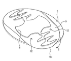
- FIG. 1 is an external perspective view of the wet tissue package according to the embodiment of the present invention in use.
- FIG. 2 is a side sectional view of the wet tissue package according to the embodiment of the present invention, showing a state before use.
- FIG. 3 is an exploded perspective view of the wet tissue package according to the embodiment of the present invention.
- FIG. 4 is a perspective view showing a state of the inside of the outlet frame body in a state where the lid body is opened in the wet tissue package according to the embodiment of the present invention.
- FIG. 5 is a perspective view of the outlet frame portion showing a state in which the flap seal is removed from the wet tissue package according to the embodiment of the present invention.
- FIG. 6 is a perspective view of the resistance imparting member as seen from the inside of the bag body when the wet tissue package according to the embodiment of the present invention is in use.
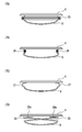
- FIG. 7 is a schematic side view of the main part showing different attachment states of the resistance applying member.
- FIG. 1 is an external perspective view of the wet tissue package 1 in use.
- the bag 3 in which the opening 2 is formed at the central portion of one surface is sealed by a heat-sealing or the like other than the opening 2 with a flexible plastic film having airtightness, For example, it is formed in a pillow-like bag shape.
- the bag body 3 may be composed of a single layer plastic film or the like, but may be composed of a multi-layer laminated film or the like.
- a wet tissue laminate 6b is accommodated in the bag 3 (FIG. 2).
- the opening 2 is formed in the central portion of one of the widest surfaces of the bag body 3 in order to draw the distal end portion 6 a of the wet tissue continuous body 6 outward.
- An annular outlet frame 4 made of a rigid plastic material or the like is attached to the opening 2.
- a lid body 5 that can close and open the opening 2 from the outside is connected to the outlet frame 4 so as to be openable and closable. In the closed state, the lid 5 is fitted over the entire circumference of the annular outer end edge 4 a of the outlet frame 4, and is formed inside the outer edge 4 a of the outlet frame 4. Occlude.
- the outlet frame body 4 and the lid body 5 are integrally formed of, for example, a thermoplastic resin such as polyethylene or polypropylene via a hinge portion 5a that serves as an axis of rotation. However, you may make it the structure which formed and combined the outlet frame 4 and the cover body 5 separately.
- the outlet frame 4 of this embodiment is formed in an annular shape such as a circle or an ellipse. However, other annular shapes may be used.
- a flange-like portion 4b is formed to protrude on the outer periphery of the bottom portion, and the outlet member 4 is formed on the lower surface side of the flange-like portion 4b so as to surround the periphery of the opening 2 at a position away from the outer edge of the opening 2.
- the bag 3 is airtightly fixed to the outer surface of the bag body 3 with an adhesive such as hot melt.
- FIG. 2 is a longitudinal sectional view of the side surface side of the wet tissue package.
- the wet tissue laminate 6b accommodated in the bag 3 is a plurality of independent single-wafer wet tissues in which a wet tissue continuum 6 in which adjacent wet tissues are overlapped with each other at the ends is folded. And are folded and stacked in a so-called Z-fold, W-fold, WZ-fold, or the like.
- the wet tissue continuum 6 is obtained by impregnating a base fabric with a drug or the like.
- a base fabric material for example, paper, woven fabric, or non-woven fabric made of synthetic fiber or natural fiber is used, but made of other materials. You may use things.
- the chemical solution include alcohols, water or a mixture thereof, such as fragrances, antibacterial agents, deodorants, surfactants, preservatives, dyes, antifoaming agents, antioxidants, clarifiers, Solubilizers and the like may be blended, and other chemicals and the like may be used.
- the lid 5 is connected to the outlet frame 4 fixed to the outer surface of the bag 3 so as to surround the opening 2 portion of the bag 3 so as to be rotatable around the hinge 5a. It is installed.
- FIG. 2 a state in which the lid 5 is closed and the outlet frame 4 is closed is illustrated by a solid line, and the lid 5 in an opened state is illustrated by a two-dot chain line.
- the opening 2 of the bag body 3 is sealed by a flap seal 20 attached to the outer surface of the bag body 3.
- FIG. 3 which is an exploded perspective view of the wet tissue package 1
- the flap seal 20 has a configuration in which the flap seal 20 is formed in a folded shape at the folded-back portion 21 and overlapped on the upper and lower two sheets.
- the lower sealing surface 22 of the flap seal 20 is formed in a size that can seal the entire opening 2, the upper knob 23 is formed narrower than the seal surface 22, and the knob 23 is a seal. It is configured as a knob when the surface 22 is peeled off. And the edge part 24 of the knob
- the flap seal 20 configured as described above has a lower surface (rear surface) of the seal surface 22 attached to the surface of the bag body 3, and as shown in FIG. Part 2 is sealed by a flap seal 20.
- the flap seal 20 does not necessarily have to be formed integrally with the sealing surface 22 and the knob 23 as shown in this embodiment. For example, a separate sealing surface and a knob are provided. Even if it is the structure etc. which were connected by the folding
- a resistance applying member 9 in which a resistance applying hole 8 for applying resistance to the passing wet tissue continuous body 6 is formed is disposed in the inner region of the outlet frame 4 (FIGS. 1 and 3).
- the resistance imparting hole 8 is a known one, and when the wet tissue continuous body 6 is pulled out from the inside of the bag body 3, friction resistance is exerted from the resistance imparting hole 8 to the wet tissue continuous body 6 passing through the inside. By acting, the wet tissue continuum 6 is separated at the separable portion at the position just passing through the resistance imparting hole 8, and the tip portion 6a of the wet tissue continuum 6 located on the front side of the separable portion. To the separable part is taken out as a single wet tissue.
- the resistance imparting hole 8 has various shapes, and any shape can be adopted. Further, the shape of the resistance imparting hole 8 is known if one wet tissue can be separated from the wet tissue continuous body 6 and a resistance capable of holding the tip of the next wet tissue continuous body 6 can be imparted to the wet tissue continuous body. It may be other than those.
- the resistance imparting member 9 in which such resistance imparting holes 8 are formed is formed integrally with or separately from the outlet frame 4, and only one end side of the resistance imparting member 9 is fixed to the outlet frame 4. In other words, it is in a so-called cantilevered state.
- the resistance applying member 9 is biased so that the free end 9 a side passes through the opening 2 and enters the bag 3.
- the urging force is applied to the resistance applying member 9 by the elasticity of the resistance applying member 9 itself, but an elastic material or the like for applying the urging force to the resistance applying member 9 may be provided separately. With such a configuration, if the flap seal 20 is removed as shown in FIG. 1, the resistance applying member 9 has a wet tissue laminate 6b as shown in FIG.
- FIG. 2 shows a state where the flap seal 20 is not removed, the movement of the resistance applying member 9 has been described as the flap seal 20 being removed.
- the resistance applying member 9 is inclined with respect to the drawing direction of the wet tissue continuous body 6.
- a strong frictional resistance acts on the wet tissue continuum 6 from the resistance imparting hole 8, and the leading wet tissue in the wet tissue continuum 6 can be separated and pulled out at an appropriate position.
- the resistance applying member 9 is formed integrally with the outlet frame 4 so as to protrude from the outlet frame 4 in the direction opposite to the lid 5 by 180 degrees.
- the resistance applying member 9 may be formed of a member different from the outlet frame 4 and attached by a method such as engaging with the outlet frame 4.
- the lid 5 is used so that the outlet of the outlet forming member 4 can be opened and closed by rotating in the direction of arrow A shown in FIG.
- the resistance applying member 9 is rotated in the direction of the arrow B, and the connecting portion 9b with the outlet frame 4 is bent, and the inside of the outlet frame 4 from the bottom side of the outlet frame 4 (the outlet side) ).
- a biasing force in the direction opposite to the arrow B is generated in the resistance applying member 9. Therefore, if the outlet frame 4 is to be attached to the bag 3 at the time of manufacturing and assembling, the resistance imparting member 9 may jump out of the outlet frame 4 and it may be difficult to smoothly assemble.
- the short pin-shaped holding body 11 that can be detachably engaged with the resistance applying member 9 to hold the resistance applying member 9 in the region in the outlet frame 4 is provided with the lid 5.
- the above problem is solved by providing the engagement hole 12 on the resistance applying member 9 side in which the holding body 11 is elastically fitted.
- the holding body 11 can be formed integrally with the lid 5, and if a device such as a slit is formed on the head of the holding body 11, the engagement force of the holding body 11 with respect to the engagement hole 12 is further increased. It will be stable.
- the resistance applying member 9 is attracted and held near the lid body 5. Is done. With this configuration, when the take-out frame body 4 is fixed to the bag body 3, the fixing operation of the take-out frame body 4 is not hindered by the resistance-applying member 9 projecting downward, and the attachment is smooth. Can be done. After the wet tissue package 1 is manufactured, the state is maintained until the lid 5 is opened for the first time. Then, once the lid 5 is opened, the holding body 11 and the engagement hole 12 are disengaged, and the holding state of the resistance applying member 9 by the holding body 11 is released.
- FIG. 4 shows the state in the outlet frame 4 when the lid 5 is opened after the outlet frame 4 is attached to the outer surface side of the bag 3 in which the opening 2 is sealed with the flap seal 20. Show. At this time, since the holding state of the resistance applying member 9 by the holding body 11 is released, the resistance applying member 9 is pressed against the flap seal 20 side by the urging force. Therefore, when the flap seal 20 is peeled off and the use is started, as shown in FIG. 5, the free end 9a side of the resistance applying member 9 is lifted upward, and the end 24 of the tab 23 of the flap seal 20 is picked with a fingertip.
- FIG. 6 shows a state of the resistance applying member 9 at that time as viewed from the inside of the bag body 3, and the free end of the resistance applying member 9 biased toward the inside of the bag body 3 (in the direction of arrow C).
- the 9a side enters the bag 3 through the opening 2 and is pressed against the surface of the wet tissue laminate 6b (not shown).
- the holding body 11 does not necessarily have to be a short pin-like member formed to protrude on the back side of the lid body 5.
- any shape and structure may be used as long as they can be appropriately held in the body 4. Further, not only the structure in which the holding body 11 and the engagement hole 12 of the resistance applying member 9 are disengaged when the cover 5 is opened, but resistance is applied manually after the cover 5 is opened. It may be configured to disengage from the member 9. Furthermore, the holding body 11 is not limited to being provided on the back surface side of the lid body 5, but can be provided on the outlet frame body 4 or the like.
- the opening 2 of the bag body 3 is sealed with the flap seal 20 and the flap seal 20 is peeled off in use.
- the opening 2 is sealed in a half cut shape with the seal. In use, the half cut portion may be pushed into the bag 3 or peeled off and opened.
- the outlet of the outlet frame 4 can be sealed with a pull-top lid, and the pull-top lid can be pulled out and opened in use.
- both ends of the resistance provision member 9 are shown in FIG. It is good also as what is called a both-ends support fixed to the exit frame 4.
- both ends of the resistance applying member 9 may be attached to the bellows 25 fixed to the outlet frame 4, and the resistance applying member 9 may be biased by the restoring force of the compressed bellows 25. .
- FIG. 7A both ends of the resistance applying member 9 may be attached to the bellows 25 fixed to the outlet frame 4, and the resistance applying member 9 may be biased by the restoring force of the compressed bellows 25.
- both ends of the resistance applying member 9 are fixed to the other end of the spring 26 whose one end is fixed to the outlet frame 4, and the resistance applying member 9 is restored by the restoring force of the compressed spring 26. May be energized.
- the resistance applying member 9 may be fixed to the elastic body 27 instead of the spring, and the elastic body 27 may be compressed so as to be bent and urged by its restoring force.
- FIG. 7D one end of a rod-like support 28 made of an elastic body or the like is bent and attached to the outlet frame 4, and the other end of the support 28 is fixed to the resistance applying member 9 and compressed.
- the resistance applying member 9 may be biased by a restoring force when the bent portion 28a is compressed.
- the elastic body examples include rubber, plastic, and the like, and any other elastic material is not limited thereto, but rubber and plastic are usually preferable.
Abstract
Description
そのような袋状のウェットティッシュ包装体においては、ウェットティッシュ連続体の先端付近以外の部分を折り重ね合わせて形成されたウェットティッシュ積層体が袋体内に収納されていて、ウェットティッシュ連続体を先端側から外方向に引き出すための開口部が袋体の一つの面に形成されている(例えば、特許文献1、2)。
すると、ウェットティッシュ積層体の表面と抵抗付与孔との間隔が離れることにより、抵抗付与孔を通過するウェットティッシュ連続体の緊張状態が緩くなり、その結果、ウェットティッシュ連続体に付与される抵抗が小さくなってウェットティッシュ連続体が抵抗付与孔をすり抜け易くなる。
その結果、ウェットティッシュ連続体から1枚のウェットティッシュがうまく分離しなくなったり、ウェットティッシュ連続体からのウェットティッシュの分離のタイミングに遅れが発生したりして、使用者の意に反してウェットティッシュが複数枚連なって出てきてしまうという問題が生じる。また、取出口が蓋によって確実に閉じられなくなり、ウェットティッシュ連続体が袋体内で乾燥して使用時の品質の低下を招いてしまったりする場合がある。
本発明のウェットティッシュ包装体は、袋体の開口部が、開口部を封止するシール面と、該シール面周縁から連設して設けられ、シール面の上面側に折り返し形成された引き剥がし用の摘み片とを有するフラップシールのシール面を、袋体外表面に貼着して密閉されていても良い。また本発明のウェットティッシュ包装体は、抵抗付与部材の一端が上記取出口枠体に支持され、他端の自由端側が付勢力により上記ウェットティッシュ積層体の表面に押し付けられるように構成されていても良く、抵抗付与部材は、取出口枠体と一体に形成されていても良い。
図1~図6は本発明の一実施例のウェットティッシュ包装体を示している。
図1はウェットティッシュ包装体1の使用状態の外観斜視図である。開口部2が一つの面の中央部分に形成された袋体3は、気密性を有する可撓性のあるプラスチックフィルム等により、開口部2以外の開放部分をヒートシール等によって封止して、例えばピロー形状の袋状に形成されている。袋体3は一層構造のプラスチックフィルム等で構成してよいが、複数層の積層フィルム等で構成してもよい。袋体3の内部には、ウェットティッシュ積層体6bが収納されている(図2)。
開口部2は、ウェットティッシュ連続体6の先端部分6aを外方に引き出すために、袋体3の最も広い一方の面の中央部分に開口形成されている。開口部2には剛性あるプラスチック材等からなる環状の取出口枠体4が取り付けられている。そして、取出口枠体4には、開口部2を外方から閉塞及び開放自在な蓋体5が開閉自在に連設されている。蓋体5は、閉じられた状態では、取出口枠体4の環状の外端縁部4aの全周にわたって嵌合し、取出口枠体4の外端縁部4a内側に形成される取出口を閉塞する。取出口枠体4と蓋体5は、例えばポリエチレン、ポリプロピレン等の熱可塑性樹脂により、回動動作の軸になるヒンジ部5aを介して一体成型で形成されている。ただし、取出口枠体4と蓋体5を別体で形成して組み合わせた構成にしてもよい。
この実施例の取出口枠体4は、例えば円形又は楕円形状のような環状に形成されている。ただしその他の環状形状であっても差し支えない。そして、その底部外周には鍔状部4bが突出形成され、取出口部材4は、開口部2の外縁から離れた位置において開口部2の周囲を囲むように、鍔状部4bの下面側を、袋体3の外表面にホットメルト等の接着剤により気密に固着されている。
それにより、ウェットティッシュ連続体6の先端部分6aが開口部2から外方に引き出された場合、その引き出されたウェットティッシュ連続体6の後端が、次に積層されたウェットティッシュ連続体6の先端と接触しなくなることにより、一枚のウェットティッシとしてウェットティッシュ連続体6から分離される。
ウェットティッシュ連続体6は、基布に薬剤等を含浸させたもので、基布素材としては、例えば合成繊維若しくは天然繊維からなる紙、織布又は不織布等が用いられるが、その他の材料からなるものを使用しても良い。また薬液等としては、例えば、アルコール類、水又はこれらの混合物があげられるが、香料、抗菌剤、消臭剤、界面活性剤、防腐剤、色素、消泡剤、酸化防止剤、清澄剤、可溶化剤等を配合してもよく、またその他の薬液等を使用してもよい。
袋体3の開口部2は、袋体3の外面に貼着されたフラップシール20により密閉されている。フラップシール20は、ウェットティッシュ包装体1の分解斜視図である図3に詳細に図示されているように、折り返し部21にて二つ折り状に形成されて上下二枚に重ね合わされた構成を有している。フラップシール20の下側のシール面22は、開口部2全体を密封することができる大きさに形成され、上側の摘み片23はシール面22よりも細幅に形成され、摘み片23はシール面22を引き剥がす際の摘み部として構成されている。そして、折り返し部21から離れた位置にある摘み片23の端部24は、指先で摘み易いように、シール面22の外周縁より少し外方に突出するように形成されている。
そのように構成されたフラップシール20は、シール面22の下面(裏面)が袋体3の表面に貼着され、図2に示されるように、未使用状態のウェットティッシュ包装体においては、開口部2がフラップシール20により密封されている。その結果、ウェットティッシュ包装体が長期間保存されたような場合でも、袋体3内のウェットティッシュ積層体6bが乾燥せず、また取出口枠体4を袋体3に接着する接着剤がウェットティッシュ積層体6bから発生する薬剤等の蒸気の悪影響を受けない等のメリットがある。なお、フラップシール20は必ずしもこの実施例に示したような、シール面22と摘み片23とが一体に形成されたものである必要はなく、例えば、別体のシール面と摘み片とを、折り返し部21により連結した構成等であっても差し支えない。
そのような抵抗付与孔8が形成された抵抗付与部材9は、取出口枠体4と一体又は別体に形成されていて、取出口枠体4に抵抗付与部材9の一端側のみが固定された、所謂、片持ち支持された状態になっている。そして、その抵抗付与部材9の自由端9a側が開口部2内を通って袋体3内に入るように付勢されている。この実施例では、抵抗付与部材9自体が有する弾性により付勢力が抵抗付与部材9に付与されているが、抵抗付与部材9に付勢力を与えるための弾性材等を別設してもよい。
そのような構成により、図1に示されるようにフラップシール20が取り外された状態であれば、抵抗付与部材9は、図2に示すように、自由端9a側が付勢力によりウェットティッシュ積層体6bの嵩高の減少量に応じて二点鎖線で示す位置から一点鎖線で示す位置へと袋体3内で下方に移動し、ウェットティッシュ積層体6bの嵩高が低下しても、抵抗付与部材9がウェットティッシュ積層体6bの表面に押し付けられた状態が持続される。なお、図2にはフラップシール20が取り外されていない状態が図示されているが、抵抗付与部材9の移動に関してはフラップシール20が取り外されているものとして説明をした。
そのような抵抗付与部材9は、例えば図3に示されるように、取出口枠体4から蓋体5と180度逆の方向に突出する状態で、取出口枠体4と一体成型で形成されている。ただし、抵抗付与部材9を取出口枠体4とは別の部材で形成し、取出口枠体4に係合する等の方法で取り付けても差し支えない。蓋体5は、図3に示される矢印A方向に回動させ、取出口形成部材4の取出口が開閉可能となるように使用される。一方、抵抗付与部材9は、矢印B方向に回動させて取出口枠体4との連結部9bが折り曲げられ、取出口枠体4の底部側から取出口枠体4の内側(取出口側)に位置するように配置される。その結果、抵抗付与部材9に矢印Bと逆方向の付勢力が発生する。
したがって、製造組立時に取出口枠体4を袋体3に取り付けようとすると、抵抗付与部材9が取出口枠体4内から飛び出してしまってスムーズに組み立てを行うのが困難となる虞がある。そこで、この実施例では、抵抗付与部材9と係脱自在に係合して抵抗付与部材9を取出口枠体4内の領域に保持することができる短ピン状の保持体11を蓋体5の裏面から突出して設けるとともに、この保持体11が弾力的に嵌め込まれる係合孔12を抵抗付与部材9側に設けることで、上記のような問題を解決している。保持体11は蓋体5に一体成型により形成することができ、また保持体11の頭部にスリ割りを形成するなどの工夫を加えれば、係合孔12に対する保持体11の係合力がより安定したものになる。
なお、保持体11は抵抗付与部材9を保持できる構造のものであれば、必ずしも蓋体5の裏側に突出形成された短ピン状の部材でなくてもよく、抵抗付与部材9を取出口枠体4内に適宜に保持できるものであればいかなる形状、構造であっても良い。また、蓋体5を開いた時に保持体11と抵抗付与部材9の係合孔12との係合が外れるように構成されたものに限らず、蓋体5を開いた後に、手動で抵抗付与部材9との係合を外すように構成されたものであっても差し支えない。更に、保持体11は蓋体5の裏面側に設ける場合に限らず、取出口枠体4等に設けることもできる。
Claims (5)
- 複数枚の独立した枚葉のウェットティッシュを隣り合うウェットティッシュを互いに端部どうしで重ね合わせたウェットティッシュ連続体を折り畳たんだウェットティッシュ積層体と、該ウェットティッシュ積層体が収納される袋体と、該袋体に設けられたウェットティッシュ取り出し用の開口部と、該開口部から引き出したウェットティッシュを外方に取り出すための取出口を有する取出口枠体と、該取出口枠体に取り付けられ、取出口を閉塞及び開放可能な蓋体とを有するウェットティッシュ包装体において、
前記取出口枠体の袋体側には、ウェットティッシュ連続体に抵抗を付与する方向に付勢された抵抗付与孔を有する抵抗付与部材があり、前記抵抗付与部材は、少なくともその一部が袋体の開口部から袋体内に進入可能に設けられているとともに、取出口枠体の下面が袋体の外面側に、袋体の開口部を取り囲むように取り付けられているウェットティッシュ包装体。 - 袋体の開口部は、開口部を封止するシール面と、該シール面周縁から連設して設けられ、シール面の上面側に折り返し形成された引き剥がし用の摘み片とを有するフラップシールのシール面を、袋体外表面に貼着して密閉されている請求項1記載のウェットティッシュ包装体。
- 抵抗付与部材を、付勢力に抗して取出口枠体に係止される保持体を有する請求項1又は2記載のウェットティッシュ包装体。
- 上記抵抗付与部材は、一端が上記取出口枠体に支持され、他端の自由端側が付勢力により上記ウェットティッシュ積層体の表面に押し付けられるように構成されている請求項1~3のいずれかに記載のウェットティッシュ包装体。
- 上記抵抗付与部材は、上記取出口枠体と一体に形成されている請求項4記載のウェットティッシュ包装体。
Priority Applications (5)
| Application Number | Priority Date | Filing Date | Title |
|---|---|---|---|
| JP2015522254A JPWO2014199409A1 (ja) | 2013-06-10 | 2013-06-10 | ウェットティッシュ包装体 |
| CN201380077338.0A CN105283391A (zh) | 2013-06-10 | 2013-06-10 | 湿纸巾包装体 |
| US14/894,880 US9730562B2 (en) | 2013-06-10 | 2013-06-10 | Wet wipe packaging body |
| EP13886848.4A EP3009376A4 (en) | 2013-06-10 | 2013-06-10 | Wet wipe packaging |
| PCT/JP2013/003637 WO2014199409A1 (ja) | 2013-06-10 | 2013-06-10 | ウェットティッシュ包装体 |
Applications Claiming Priority (1)
| Application Number | Priority Date | Filing Date | Title |
|---|---|---|---|
| PCT/JP2013/003637 WO2014199409A1 (ja) | 2013-06-10 | 2013-06-10 | ウェットティッシュ包装体 |
Publications (1)
| Publication Number | Publication Date |
|---|---|
| WO2014199409A1 true WO2014199409A1 (ja) | 2014-12-18 |
Family
ID=52021746
Family Applications (1)
| Application Number | Title | Priority Date | Filing Date |
|---|---|---|---|
| PCT/JP2013/003637 WO2014199409A1 (ja) | 2013-06-10 | 2013-06-10 | ウェットティッシュ包装体 |
Country Status (5)
| Country | Link |
|---|---|
| US (1) | US9730562B2 (ja) |
| EP (1) | EP3009376A4 (ja) |
| JP (1) | JPWO2014199409A1 (ja) |
| CN (1) | CN105283391A (ja) |
| WO (1) | WO2014199409A1 (ja) |
Cited By (6)
| Publication number | Priority date | Publication date | Assignee | Title |
|---|---|---|---|---|
| USD837661S1 (en) | 2017-11-09 | 2019-01-08 | The Clorox Company | Wipes dispenser opening |
| US10278552B2 (en) | 2016-12-08 | 2019-05-07 | The Clorox Company | Disinfecting wipes flex pack closure |
| US10894656B2 (en) | 2016-11-11 | 2021-01-19 | Kimberly-Clark Worldwide, Inc. | Storing and dispensing container for wipes |
| CN112297517A (zh) * | 2019-11-01 | 2021-02-02 | 高野朗 | 盖部件的制造方法 |
| JP2021011299A (ja) * | 2019-07-08 | 2021-02-04 | オオサキメディカル株式会社 | 取出装置および容器 |
| JP2021035848A (ja) * | 2019-08-30 | 2021-03-04 | 株式会社タイキ | ウェットシート包装体 |
Families Citing this family (19)
| Publication number | Priority date | Publication date | Assignee | Title |
|---|---|---|---|---|
| US20170150852A1 (en) * | 2015-12-01 | 2017-06-01 | Em Corporation | Water tissue |
| EP3263482B1 (en) * | 2016-07-01 | 2018-09-19 | Sulzer Mixpac AG | Cartridge, core, mold and method of manufacturing a cartridge |
| US10766671B2 (en) | 2017-05-23 | 2020-09-08 | Nice-Pak Products, Inc. | Lid assembly for container |
| EP3438016A1 (en) * | 2017-08-02 | 2019-02-06 | The Procter & Gamble Company | Package of disposable wipes |
| CN207712600U (zh) * | 2017-11-30 | 2018-08-10 | 上海久连环保材料有限公司 | 一种可快速拆卸并更换的湿巾翻盖 |
| USD912513S1 (en) | 2018-06-29 | 2021-03-09 | Kimberly-Clark Worldwide, Inc. | Lid with push-button |
| USD912514S1 (en) * | 2018-06-29 | 2021-03-09 | Kimberly-Clark Worldwide, Inc. | Lid with push-button |
| EP3611112B1 (en) * | 2018-08-13 | 2021-06-09 | The Procter & Gamble Company | Package of disposable wipes |
| US10980376B2 (en) * | 2018-09-17 | 2021-04-20 | Nathan Sutterer | Multi-purpose storage and dispensing apparatus |
| JP6962890B2 (ja) * | 2018-09-28 | 2021-11-05 | 大王製紙株式会社 | ウェットシート積層体、ウェットシート包装体及びウェットシート積層体の製造方法 |
| US10470621B1 (en) * | 2019-01-04 | 2019-11-12 | Julie Moore | Universal cover for hygiene cloth dispensers |
| JP6554741B1 (ja) * | 2019-02-22 | 2019-08-07 | 進一 塚本 | 包装体 |
| USD937087S1 (en) * | 2020-03-05 | 2021-11-30 | Kimberly-Clark Worldwide, Inc. | Packaging box with lid |
| USD937675S1 (en) | 2020-03-05 | 2021-12-07 | Kimberly-Clark Worldwide, Inc. | Lid for packaging box |
| CN111991250B (zh) * | 2020-06-22 | 2023-04-18 | 浙江新远实业有限公司 | 一种清凉驱蚊湿巾整理液及其制备方法 |
| WO2022097220A1 (ja) * | 2020-11-05 | 2022-05-12 | 塚本進一 | 包装体 |
| USD964860S1 (en) * | 2021-02-24 | 2022-09-27 | Kimberly-Clark Worldwide, Inc. | Package with lid |
| KR102376033B1 (ko) * | 2021-03-18 | 2022-03-18 | 스티븐 준 한 | 접촉 없이 세정 티슈의 인출이 가능한 티슈 케이스 및 그 밀폐방법 |
| CN114194628B (zh) * | 2021-12-08 | 2023-03-10 | 福建鼻涕虫护理用品股份有限责任公司 | 环保易降解袋装湿巾 |
Citations (5)
| Publication number | Priority date | Publication date | Assignee | Title |
|---|---|---|---|---|
| JPH06292639A (ja) * | 1993-04-08 | 1994-10-21 | Jiekusu Kk | 皮膚清拭用品の包装袋 |
| JPH09132280A (ja) * | 1995-11-08 | 1997-05-20 | Uni Charm Corp | 濡れナプキン収納容器 |
| JP2004196303A (ja) | 2002-12-16 | 2004-07-15 | Meisei Sansho Kk | ウエットティッシュ包装体 |
| JP2004331158A (ja) | 2003-05-08 | 2004-11-25 | Dipro:Kk | ウエットティッシュ包装体 |
| JP2010173649A (ja) | 2009-01-27 | 2010-08-12 | Kenji Fujimaki | ウエットティッシュ包装体 |
Family Cites Families (11)
| Publication number | Priority date | Publication date | Assignee | Title |
|---|---|---|---|---|
| US3265242A (en) | 1964-08-06 | 1966-08-09 | Georgia Pacific Corp | Tissue dispenser with a movable dispensing sheet |
| US3473694A (en) * | 1967-08-25 | 1969-10-21 | Int Paper Canada | Carton |
| US4848575A (en) * | 1988-03-02 | 1989-07-18 | Eluci Company Inc. | Resealable dispenser-container for wet tissues |
| JP3322805B2 (ja) * | 1996-09-03 | 2002-09-09 | 中村 憲司 | ウエットティッシュ包装体 |
| US6910579B2 (en) * | 2002-05-28 | 2005-06-28 | Georgia-Pacific Corporation | Refillable flexible sheet dispenser |
| WO2005023677A1 (en) * | 2003-09-08 | 2005-03-17 | Edmak Limited | Dispenser-container for wet wipes |
| JP5512116B2 (ja) | 2008-11-14 | 2014-06-04 | ユニ・チャーム株式会社 | 開閉自在容器 |
| US8245876B2 (en) * | 2009-07-15 | 2012-08-21 | The Procter & Gamble Company | Wipes container |
| JP5590914B2 (ja) * | 2010-02-25 | 2014-09-17 | 大王製紙株式会社 | 家庭用薄葉紙収納容器 |
| JP5912288B2 (ja) * | 2010-11-25 | 2016-04-27 | 山田 菊夫 | ウェットティッシュ包装体 |
| US8210393B1 (en) * | 2011-01-24 | 2012-07-03 | Prodius, LLC | Tissue dispensing device |
-
2013
- 2013-06-10 CN CN201380077338.0A patent/CN105283391A/zh active Pending
- 2013-06-10 WO PCT/JP2013/003637 patent/WO2014199409A1/ja active Application Filing
- 2013-06-10 EP EP13886848.4A patent/EP3009376A4/en not_active Withdrawn
- 2013-06-10 US US14/894,880 patent/US9730562B2/en active Active
- 2013-06-10 JP JP2015522254A patent/JPWO2014199409A1/ja active Pending
Patent Citations (5)
| Publication number | Priority date | Publication date | Assignee | Title |
|---|---|---|---|---|
| JPH06292639A (ja) * | 1993-04-08 | 1994-10-21 | Jiekusu Kk | 皮膚清拭用品の包装袋 |
| JPH09132280A (ja) * | 1995-11-08 | 1997-05-20 | Uni Charm Corp | 濡れナプキン収納容器 |
| JP2004196303A (ja) | 2002-12-16 | 2004-07-15 | Meisei Sansho Kk | ウエットティッシュ包装体 |
| JP2004331158A (ja) | 2003-05-08 | 2004-11-25 | Dipro:Kk | ウエットティッシュ包装体 |
| JP2010173649A (ja) | 2009-01-27 | 2010-08-12 | Kenji Fujimaki | ウエットティッシュ包装体 |
Non-Patent Citations (1)
| Title |
|---|
| See also references of EP3009376A4 * |
Cited By (10)
| Publication number | Priority date | Publication date | Assignee | Title |
|---|---|---|---|---|
| US10894656B2 (en) | 2016-11-11 | 2021-01-19 | Kimberly-Clark Worldwide, Inc. | Storing and dispensing container for wipes |
| US10278552B2 (en) | 2016-12-08 | 2019-05-07 | The Clorox Company | Disinfecting wipes flex pack closure |
| USD837661S1 (en) | 2017-11-09 | 2019-01-08 | The Clorox Company | Wipes dispenser opening |
| JP2021011299A (ja) * | 2019-07-08 | 2021-02-04 | オオサキメディカル株式会社 | 取出装置および容器 |
| JP2021035848A (ja) * | 2019-08-30 | 2021-03-04 | 株式会社タイキ | ウェットシート包装体 |
| CN112297517A (zh) * | 2019-11-01 | 2021-02-02 | 高野朗 | 盖部件的制造方法 |
| WO2021084846A1 (ja) * | 2019-11-01 | 2021-05-06 | 朗 高野 | 蓋部材及びその製造方法 |
| CN112297517B (zh) * | 2019-11-01 | 2021-06-11 | 高野朗 | 盖部件的制造方法 |
| JP2022007860A (ja) * | 2019-11-01 | 2022-01-13 | 朗 高野 | 蓋部材の製造方法 |
| JP2022007850A (ja) * | 2019-11-01 | 2022-01-13 | 朗 高野 | 蓋部材 |
Also Published As
| Publication number | Publication date |
|---|---|
| US20160113450A1 (en) | 2016-04-28 |
| CN105283391A (zh) | 2016-01-27 |
| US9730562B2 (en) | 2017-08-15 |
| JPWO2014199409A1 (ja) | 2017-02-23 |
| EP3009376A1 (en) | 2016-04-20 |
| EP3009376A4 (en) | 2017-02-01 |
Similar Documents
| Publication | Publication Date | Title |
|---|---|---|
| WO2014199409A1 (ja) | ウェットティッシュ包装体 | |
| JP6189931B2 (ja) | ワイプディスペンサ | |
| WO2014203404A1 (ja) | ウェットティッシュ包装体 | |
| JP5905996B2 (ja) | ウェットシート包装体用蓋体及びウェットシート包装体 | |
| JP5349916B2 (ja) | 開閉自在容器 | |
| JP5512116B2 (ja) | 開閉自在容器 | |
| US7416083B2 (en) | Container for housing wet sheet package | |
| US20050189367A1 (en) | Closure unit, mold for producing same, and dispenser-container incorporating a closure unit | |
| US20150102050A1 (en) | System for dispensing non-intertwined wet wipes in a flexible container | |
| WO2013024566A1 (ja) | ウェットティッシュ包装体 | |
| TW201817659A (zh) | 蓋機構、包裝體以及分配容器 | |
| US20180184859A1 (en) | Dispensing container | |
| JP6053090B1 (ja) | ウェットティッシュの収容容器 | |
| EP1564154A1 (en) | Closure unit, mold for producing same, and dispenser-container incorporating a closure unit | |
| JP2008100752A (ja) | 保湿容器 | |
| JP2012066864A (ja) | 包装体 | |
| JPH09226861A (ja) | ウエットティッシュ包装体 | |
| JP6053089B1 (ja) | ウェットティッシュの収容容器 | |
| KR101257312B1 (ko) | 물티슈용 포장팩 |
Legal Events
| Date | Code | Title | Description |
|---|---|---|---|
| WWE | Wipo information: entry into national phase |
Ref document number: 201380077338.0 Country of ref document: CN |
|
| 121 | Ep: the epo has been informed by wipo that ep was designated in this application |
Ref document number: 13886848 Country of ref document: EP Kind code of ref document: A1 |
|
| ENP | Entry into the national phase |
Ref document number: 2015522254 Country of ref document: JP Kind code of ref document: A |
|
| WWE | Wipo information: entry into national phase |
Ref document number: 14894880 Country of ref document: US |
|
| NENP | Non-entry into the national phase |
Ref country code: DE |
|
| WWE | Wipo information: entry into national phase |
Ref document number: 2013886848 Country of ref document: EP |